

Daewoo DPC-8200PD Schematic
OSDPC82001
(8.0-Inch) LCD Color Monitor &
DVD Player
DPC-8200PD
NOV. 2006

(8.0-Inch) LCD Color Monitor &DVD Player
MODEL : DPC-8200PD
CONTENTS
----------------
Specification.......................................................…...............................................…………….…..
Block Diagram...................................…................................................................…………….…..
General Alignment Instruction.......................................................................……….…….....…
Troubleshooting...........................................................................................…...……………...…..
Printed Circuit Board........................................................................................……………...…...
IC BLOCK DIAGRAM & DESCRIPTION.......................................................…………..…..
2
4
6
7
9
14
Explode View........................................................................................................…………......….
Schematic Diagram.........................................................................................…………….....…..
28
29
LCD MONITOR
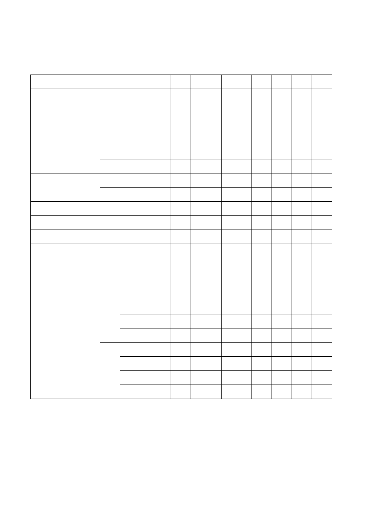
SPECIFICATION
Description Condition Unit
Headphone1 Output 1KHz 0dB mW
Headphone2 Output 1KHz 0dB mW
Headphone1 Noise No Signal mV <1mV <1mV
Headphone2 Noise No Signal mV <1mV <1mV
L 1KHz 0dB mW
SPK MAX Output
R 1KHz 0dB mW
L 1KHz 0dB mW
SPK MAX Output(AV IN)
R 1KHz 0dB mW
REF THD 1KHz 0dB % 5 3
SPK S/N Infinity zere/- dB/L&R dB
Headphone S/N Infinity zere/- dB/L&R dB
Luminance(MAX) White Signal LUX 300±50
Limit Nominal
3±2 3
3±2 3
600±100
600±100
600±100
600±100
≥35 ≥35
≥60 ≥60
600
600
600
600
300
Luminance(8STEP) White Signal LUX 250±50
Luminance(MIN) White Signal LUX 100±50
20Hz dB ±3 0
125Hz dB ±3 0
1
10KHz dB ±3 0
20KHz dB ±3 0
Headphone RESP
20Hz dB ±3 0
125Hz dB ±3 0
2
10KHz dB ±3 0
20KHz dB ±3 0
250
100
-2-
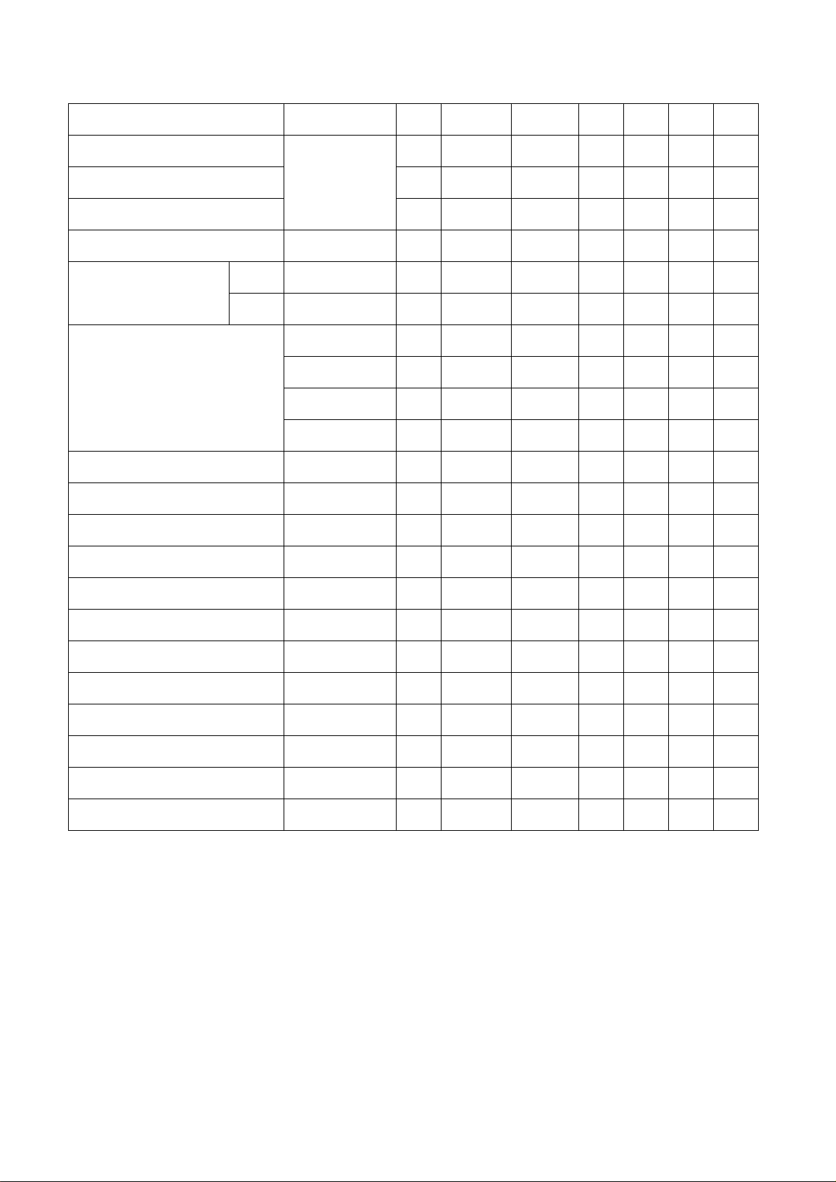
DVD
Description Condition Unit
Limit Nominal
Video Signal Level Vp-p 0.7±0.1
75% color
SYNC Level Vp-p 0.3±0.1
bar/75ohm
Video out level
Vp-p 1.0±0.2
Video out level(Unload) 75% color bar Vp-p 2.0±0.2
CD 1KHz/0dB/10K V 2.0±0.2
Audio out level
DVD
FREQ RESP (DVD)
(20Hz~20KHz)
1KHz/0dB/10K
20Hz
125Hz
10KHz
20KHz
Signal-to-noise radio Infinity zere/- dB/L&R dB
Audio distortion&noise (DVD) 1KHz/0dB/L&R dB
V 2.0±0.2
dB
dB
dB
dB
≤±3
≤±3
≤±3
≤±3
≥60 ≥60
≤-65
0.7
0.3
1
2
2
2
0
0
0
0
-65
Dynamic range (DVD) 1KHz/-60dB dB
R/L Cross sound (DVD) 1KHz/0dB/L&R dB
1KHz Channel unbalance (DVD) 1KHz/0dB/L&R dB
≥85 ≥85
≥45 ≥45
≤3
0
Power Consumption Standby W 0 0
DC 9V Rating W
Eccentricity A BEX TDV-552 um
Scratch A BEX TDV-541 mm
Black dot A BEX TDV-545 mm
Finger Print A BEX TDV-545 um
Vertical deviation A BEX TDV-533 mm
Note: Nominal specs represent the design specs. All units should be able to approximate these. Some will
exceed and some may drop slightly below these specs. Limit specs represent the absolute worst condition that
might still be considered acceptable. In no case should a unit fail to meet limit specs.
≤12 ≤12
≥100
≥1.6
≥ф0.8
≥ф65
≥0.6
100
1.6
0.8
65
0.6
-3-
LCD
H
S
Y
N
C
S
W
R
G
B
8
D
0
2
D
8
”
P
a
n
a
s
o
n
i
c
P
A
N
E
L
H
I
G
H
V
O
L
T
A
G
E
O
S
C
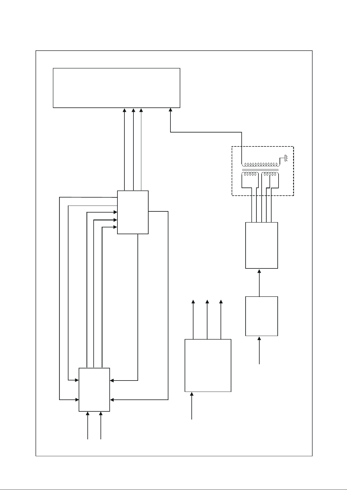
BLOCK DIAGRAM
H.V.
TRAN
D3031
YC
-4-
+12V
DC
+7V
A8430
-10V
O Z970
DC
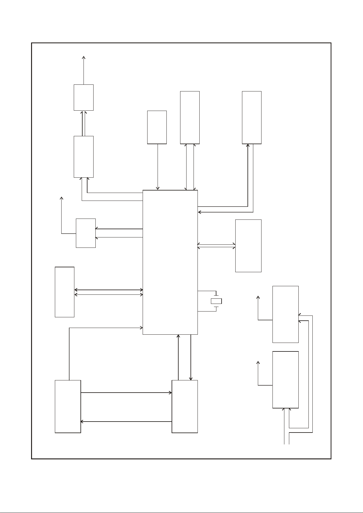
DVD
16BIT BUSL&R OUTL&R
AUDIO DATA BU
S
FOCUS TRACK SLED DRIVER
M
OTOR VELO
CIT
Y
IC DATAIC CLK
R F SIG
NAL G
ROU
P
AMP
AUDIO
SENSOR
REMOTE
AUDIO DAC
VIDEO OUT
FILTER
EEPROM
AT24C02-SOP8
VIDEO DAC
MT1389E
SERVO DSP
MPEG DECODER
SDAM 4Mx16BIT
8032MCU
RISC CONCROL
27.000MHZ
KEY BOARD
KEY SIGAL
DECODER
MICRO CODE
FLASH 1Mx8 BIT
DC/DC CONVERT
ERROR
SPINDLE
VELOCITY
FE TE DRIVER
PICK UP
DVD DECK
A5954
SERVO DRIVER
-5-
+5V +3.3V
DC/DC CONVERT
+9V INPUT

GENERAL ALIGNMENT INSTRUCTION
The Main PCB of Monitor Modification:
1. Input voltage is 6.8V-16V, input signal is test circuit BY 5418.
2. Adjust VRB1 to get test point: 15720Hz..
3. Adjust VRB2 to get horizontal phase shift.
4. Adjust VR1 to get good performance.
5. Adjust S201. S202 to get good Tint.
The main PCB of DVD Modification:
1. Adjust the brightness to the brightest by VR, adjust video pattern’s color to white, test the screen
Brightness is 200±102 LUX.
With luminometer You can adjust R250 to get this standard.
-6-
LCD
SYMPTOM CAUSE REMEDY
LCD MONITOR PART
TROUBLESHOOTING
1) Picture distortion
2) No Picture
3) No Picture, Picture no
Good
4) Color is no good
5) SYNC no good
6) TINT no good
7) NO Picture
8) Picture no good
& Defective capacitor (C201)
& Defective IC (D3031).
& Defective Q7, Q8. & Replace Q7, Q8.
& Defective X202.
& Defective IC 8D02D. & Replace IC 8D02D.
& Defective S201, S202
& Defective IC A8430. & Replace A8430.
& Defective CON1. & Replace CON1.
& Replace capacitor C201.
& Replace IC D3031.
& Replace X202.
& Replace S201,S202.
9) Brightness no good
& Defective IC M5237 Q10A. & Replace IC M5237 Q10A.
-7-

DVD
Replace keys.
DVD PART
SYMPTOM CAUSE REMEDY
1) No Power
2) No Picture
3) No Sound
4) Sound no good
& Power source is not correct.
The positive and negative does not
match the unit.
& Power button defective.
& Defective triode U7.
& Defective U10 (24C02N).
& Defective U5.
& Defective IC MTK1389E.
& Defective U14 (C4558).
& Defective U1 (14053).
& Defective U2.
& Defective U14.
& Replace power source.
& Change the position of
positive and negative.
& Replace power button.
& Replace U7.
& Replace U10 (24C02N).
& Replace U5.
& Replace IC MTK1389E.
& Replace U14 (C4558).
& Replace U1 (14053).
& Replace U2.
& Replace U14.
5) Can not read DISC
6) No key function
7) No remote control function
Remark: Upgrade the firmware step: 1. Rename the file name to “MTK.BIN”;
2. change the CDs name to “MEDIATEK”
3. copy the upgrade firmware file to CDs
4. Playback the CDs and according to cue on upgrade
& Defective U18.
& PICK-up Laser is defective.
& Defective IC MTK1389E. & Replace IC MTK1389E.
& Defective REMOTE.
& Key is Defective.
& Replace U18.
& Replace pick up.
& Replace REMOTE.
&
-8-
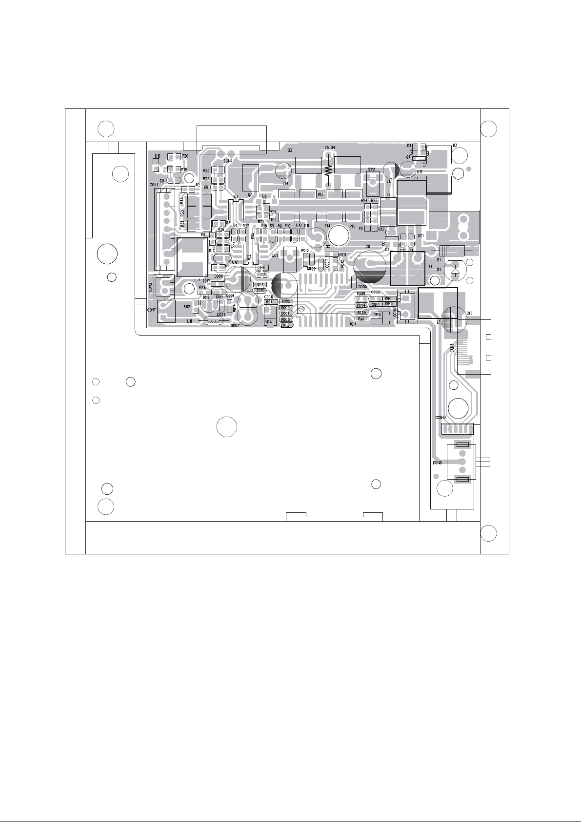
Monitor Main PCB
PRINTED CIRCUIT BOARD
Top View Bottom View
-9-
-
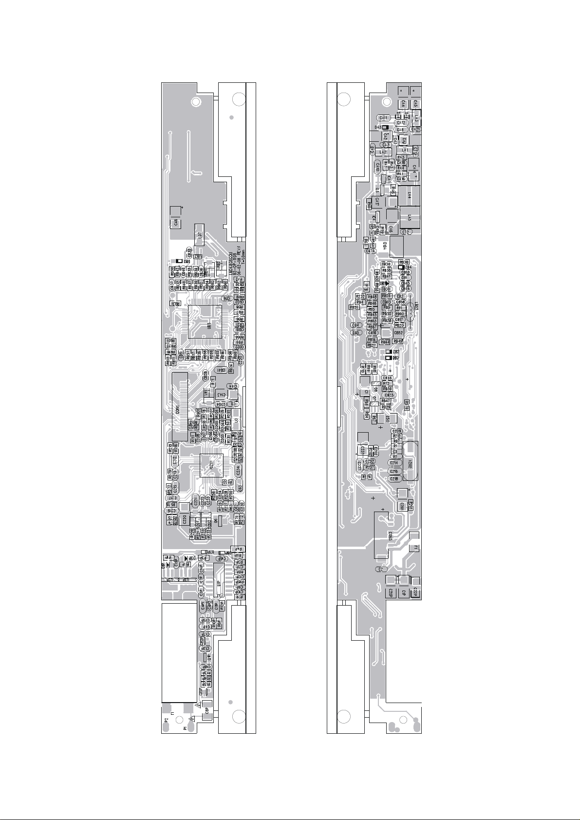
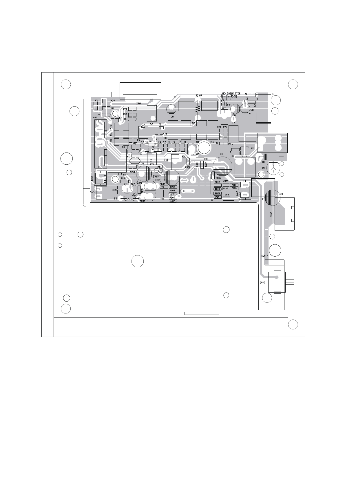
Battery Charger Circuit PCB
Top View
-10
-
Battery Charger Circuit PCB
Bottom View
-11
 Loading...