

Page 1

Service Manual
LCD TV
Panel Grade; HD Ready
Buyer Model No.: DLP-37D1
Manufacturer Model No.: LD-3760
DIGITALDEVICE, INC
1
Page 2

Contents
1. Specifications.............................................................................................................................................................................................. ................................................... 4
1-1. Description. ............................................................... ........................................................................................................................................................................... 4
1-2. Features............................................................................................................................... ................................................................................................................. 4
1-3. STRUCTURE AND PRINCIPLE OPERATION OF LCD............................................................................................................................................................................. 5
1-4. General Specification. ............................................................................................................................................................................................................................ 9
1-4-1. Specification. .............................................................................................................................................................................................................................. 9
1-4-2. I/O Description. ......................................................................................................................................................................................................................... 11
1-5. Operation Environmental Conditions....................................................................................................................................................................................................... 11
1-6. Storage Environmental Conditions.......................................................................................................................................................................................................... 11
1-7. Mechanical Test Conditions. ..................................................................................................................................................................................................................11
2. Block Diagram............................................................................................................................................................................................................................................. 12
2-1. Panel Block Diagram............................................................................................................................................................................................................................ 12
2-2. Connector Layout & Pin Assignment....................................................................................................................................................................................................... 13
2-2-1 PAL & SECAM – SCART. ........................................................................................................................................................................................................... 13
3. Board Assembling........................................................................................................................................................................................................................................ 14
3-1. Preparation. ........................................................................................................................................................................................................................................ 14
3-2. Board Assembly Diagram......................................................................................................................................................................................................................15
3-2-1 Harness Path Diagram. (PAL/SECAM). ..........................................................................................................................................................................................15
3- 3. Board Sort. ........................................................................................................................................................................................................................................ 17
3-3-1 How to sort Main PCB according to Panel Maker (LG or Samsung). .............................................................................................................................. ..................... 17
3-3-2 How to sort Tuner PCB according to System (PAL, ATSC, 3-System)................................................................
4. Set Assembly................................................................................................................................................................................................................................................ 19
4-1. Assembly Diagram............................................................................................................................................................................................................................... 19
4-1-1. Assemblage of Front Parts. .......................................................................................................................................................................................................... 19
4-1-2. Assemblage of IR. ...................................................................................................................................................................................................................... 20
4-1-3. Sub Panel Assembly.................................................................................................................................................................................................................... 21
.................................................................................. 18
2
Page 3

4-1-4. Assembly of Panel Ass’y.............................................................................................................................................................................................................. 22
4-1-5. Assemblage of Board. ................................................................................................................................................................................................................. 23
4-1-6. Assemblage of PCB Cover. .......................................................................................................................................................................................................... 24
4-1-7. Assemblage of Rear Cover. .......................................................................................................................................................................................................... 25
4-1-8. Assemblage of Stand................................................................................................................................................................................................................... 26
4-2. Screw Part Name. ................................................................................................................................................................................................................................ 27
4-3. Part List. ............................................................................................................................................................................................................................................ 29
5. T r ouble Shooting.......................................................................................................................................................................................................................................... 30
5-1. Power Failure................................................................ ......................................................................................................................................................................31
5-2. KEY, LED-IR Control Failure................................................................ ................................................................................................................................................ 31
5-3. Picture Failure..................................................................................................................................................................................................................................... 32
5-4. Sound Failure...................................................................................................................................................................................................................................... 33
5-5. Application Failure............................................................................................................................................................................................................................... 33
6. Firmware Update Method............................................................................................................................... .............................................................................................. 34
6-1. Main Board Firmware Update. ............................................................................................................................................................................................................... 34
3
Page 4
1. Specifications.
1-1. Description.
The DLP-37D1(37 inch ) is a color active matrix TFT(Thin Film Transistor) LCD(Liquid Crystal Display) that uses amorphous silicon TFT as a switching devices. This model is composed of a
TFT LCD panel, a driver circuit and a back light system. The resolution of a 37” contains 1366 x 768 pixels and can display up to 16.7 million colors with wide viewing angle of 170° or higher in
all directions.
1-2. Features.
INCH 37
Screen Size(mm) 37.02 inches(940.3mm)
Aspect ratio 16 : 9
Resolution 1366(H) x 768(V) pixels
Pixel Pitch(mm) 0.200mm x 0.600mm x RGB
Pixel Arrangement RGB vertical stripe
Luminance/Brightness 500 cd/m2
Contrast Ratio 600 : 1
Response time(ms) 8
Display Color 8 bit - 16.7M
Color Temperature
Viewing Angle 176(Degrees)
LCD Size(mm) 877.0/878.0(H) x 516.8(V) x 55.5(D)
Page 5
1-3. STRUCTURE AND PRINCIPLE OPERATION OF LCD.
Basics of LCD Operation
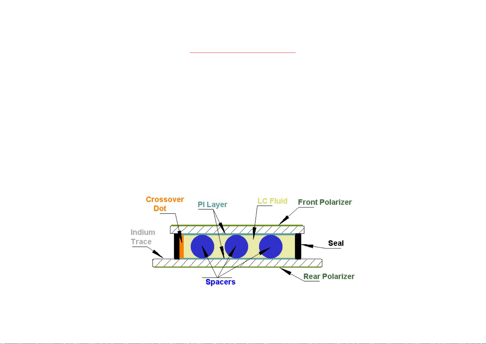
A cross sectional view of a liquid crystal display is shown below in Figure 1. As can be seen in the diagram, the display is simply two pieces of extremely flat glass, over coated with a number of
chemical layers, and filled with liquid crystal fluid.
Please notice that this drawing is not made to scale. To give some perspective, the bottom and top glass substrates are typically .043" thick each. The thin film coatings, SiO2, ITO, and PI, are each
a few hundred angstroms thick. The space in the middle, marked "LC Fluid", is about 5 microns thick and is adjusted slightly to match the characteristics of the chosen fluid. If this drawing was
made to scale, it would be very difficult to see any detail at all between the glass plates.
A liquid crystal display (LCD) is a parallel plate capacitor with a dielectric, in this case the liquid crystal fluid, between the plates. First we select glass coated with a transparent metal coating for
the electrodes of the display. The glass is usually made of soda lime, but in some instances it can be a more expensive borosilicate, or because few manufacturers provide borosilicate any more
without a fight, aluminasilicate type.
The transparent metal coating can be any thin layer of conductive material, such as gold, silver or tin. In order to keep the cost down and have a reasonable process window with a highly
transparent coating, the industry has been using indium-tin oxide (ITO) as the preferred electrode material.
Fig. 1.
5
Page 6

Photoresist is then put on top of the ITO coating and a photolithographic process is used to image the pattern. The exposed patterns are then developed and the glass is sent through an acid bath
where the excess ITO is removed, similar to the way a PC board is made. The remaining photoresist is then stripped away and the patterned segment and common plane electrodes remain on the
glass.
The next layer to be applied is the liquid crystal alignment layer. This is usually a polyimide type material and has been chosen for its environmental stability in high moisture and heat. More
importantly is its ability to cause the molecules of liquid crystal to align their long axis in the direction in which the polymer has been buffed.
We rub the two halves of the display at right angles to one another and since the liquid crystal molecules like to arrange themselves parallel to one another, we cause a helical structure to be
formed between the two electrode faces, see Fig 2 below. This helical structure forms a 90
After the polymer is rubbed, a thermoplastic seal is printed along the perimeter of one piece of glass. This is a resin based material with a high curing temperature, about 200oC, that creates an
extremely durable barrier to outside moisture and contamination. Some manufacturers use a UV cured material for this seal as it speeds up the manufacturing process.
We then apply a crossover dot, usually a small spot of silver, to connect the common plane electrode on the top piece of glass to the segment plane which is on the bottom piece of glass. This is
somewhat analogous to a plated thru hole on a PC board.
To make the display uniform in appearance, spacers are then applied. These are usually glass or plastic spheres that have the desired diameter to produce a fixed gap between the glass plates.
Depending on the liquid crystal used, this gap can be between 4 and 8 microns.
The two halves of the display are then aligned, usually with a three point camera alignment system for accuracy, and brought together. A very thin, uniform, flat and empty bottle has been formed
with the thermoplastic seal essentially "gluing" the two pieces of glass together.
A liquid crystal is put inside this bottle by using a vacuum filling technique. The liquid crystal (the dielectric material of our capacitor) is selected for it's various physical properties. The
o
rotation of the liquid crystal molecules from the top of the display to the bottom.
application may call for a liquid crystal fluid that has a very low operating voltage or the display may be used outdoors and require a very wide temperature range. Display manufacturers have
developed several liquid crystal mixtures to fulfill most applications.
Once the liquid crystal has been put inside the display and the port opening has been sealed, a polarizer is put on the front of the top glass and a second polarizer is put on the back of the bottom
glass to make sure that the light reaching the eye of the observer is oriented along the correct axis.
6
Page 7

II. Operation of a liquid crystal display.
The liquid crystal molecules are long and thin as shown in Figure 2 on the right. On the bottom glass substrate, the PI
layer has been rubbed from back to front, and the molecules are aligned in that direction. Remember, the direction of
this orientation determines the viewing angle of the part.
Because the PI layer of the top glass has been rubbed from right to left, the molecules attached to the top piece of glass
are oriented perpendicular to the ones at the bottom. This 90o rotation is the "twist" in a twisted nematic display.
The liquid crystal molecules between the top and bottom glass form a spiral structure that will twist light as it goes
Fig. 2
through the cell. As can been seen in Figure 3 on the left, a beam of light entering from above passes through the top
polarizer along the axis of polarization.
The light beam goes through the cell, and is twisted as it goes in the same direction as the twist of the LC fluid.
The light exits the display, and passes through the polarizer on the bottom glass which is oriented perpendicular to the
polarizer on the top.
Fig. 3
7
Page 8

When a drive signal is applied to the cell electrodes an electric field is set up across the cell. The liquid crystal
molecules will "stand up" to align themselves in the direction of the electric field. When the molecules "stand up" the
helical structure is disrupted, and the incoming linearly polarized light does not "twist" like it did when the molecules
were at rest. The light is instead blocked by the rear polarizer.
Fig. 4
The observer therefore sees a black segment on the clear background. When the electric field is turned off, the molecules relax back to the 90o twist structure, light
entering the cell is again twisted 90o and the display returns to a transparent state. This is referred to as a positive image, transmissive viewing mode.
The electro-optic response characteristic of our standard TN cell is asymmetric because only the "turn-on" state can be activated by an electric field. When the
RMS voltage goes to zero, the twisted structure, which provides the "twist" of the incident light, is restored by the elastic torques within the LC fluid. We can
therefore speed up the "turn-on" time of our display by increasing the drive voltage waveform (over a very limited range), but the "turn-off" time is fixed by the
relaxation characteristics of the LC fluid. Nematic liquid crystals exhibit good mechanical shock stability, because they spontaneously return to the uniform
alignment after mechanical distortion.
The typical switching times of a TN cell are in the millisecond range, however there are some things we can do to speed things up. This is a topic for long
discussions, so if you're interested, please give us a call at 1-440-232-8590 to talk to one of our applications specialists.
8
Page 9
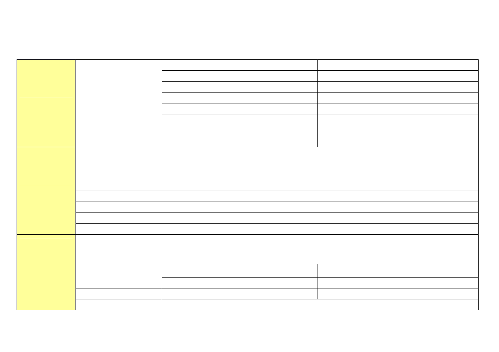
1-4. General Specification.
1-4-1. Specification.
1-4-1-1. PAL/SECAM.
HDMI Input & DVI Sound In 1
PC (RGB) 1
Component 1 1
Display Mode
TV System
TV
Features
Input Type
Component 2 1
AUDIO Line-Out 1
SCART Input 2
Power Inlet 1
RS-232C for Service 1
Video System: PAL/SECAM
Sound System: B/G, D/K, I, L/L’
FS 181 Program
FVS Tuning (max 100programs)
Fine Tuning System
Auto/Manual Programming/Sorting
1 Tuner (Built-in Tuner)
UHF/VHF/Hyper band
English,Finland,French,Germany,Spanish,Italian,Portuguese,Dutch,Swedish,Denmark,Norway,Greece,Czech,Hungarian,
Multi-Language OSD
Polish,Russian,Turkish,Arabic,Persian
Picture Mode
TV, Composite, S-Video, Component Wide / Panorama / Zoom / 14:9 / 4:3
HDMI, PC Wide / Real / 4:3
Color Temperature PC/HDMI/Component Normal / Warm1 / Warm2 / Cool1 / Cool2
90˚ Picture Rotation NO
9
Page 10
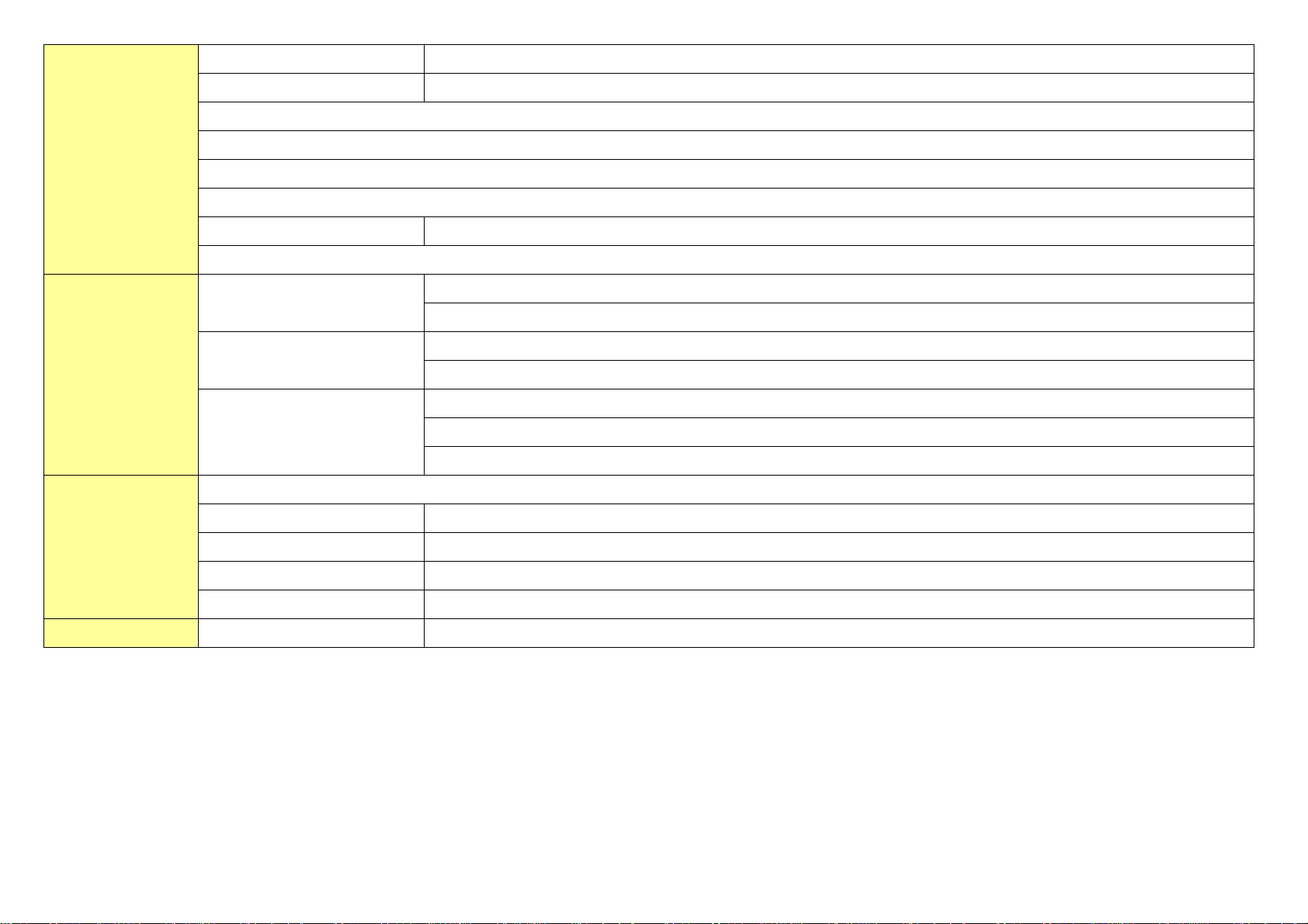
Multi-Step Zoom NO
Sleep Timer off ~ 180 minutes
Picture in Picture (PIP) with 4 corner position
Multi Picture (Twin, PIP, size, Position, Swap)
TWIN Window (Picture by Picture)
Picture Still
Teletext(No. of pages) 252 pages
Audio Mute
Input Port
Power Source
Sound
PC(Analog RGB)
VGA, SVGA, XGA, SXGA
Max. 1280 x 1024 / 60Hz
Y/Cb/Cr (Uncompressed)
HDMI
Max pixel input: 1920 x 1080i
Picture : PAL, NTSC
Video Input System
Audio : PAL,NTSC
Component - Y.Pb(Cb),Pr(Cr) : 480i ~ 1080i
Stereo (A2 / NICAM) / Dual (Mono / Stereo / bilingual)
Audio Mode Standard / Music / Movie / Speech / Custom
Audio Output 10W Per Channel @ 6 Ohm (Analog)
Impedance 6 Ω(L) + 6 Ω(R)
Speaker Internal Speaker
Free Voltage AC 100~240V 50/60Hz
10
Page 11
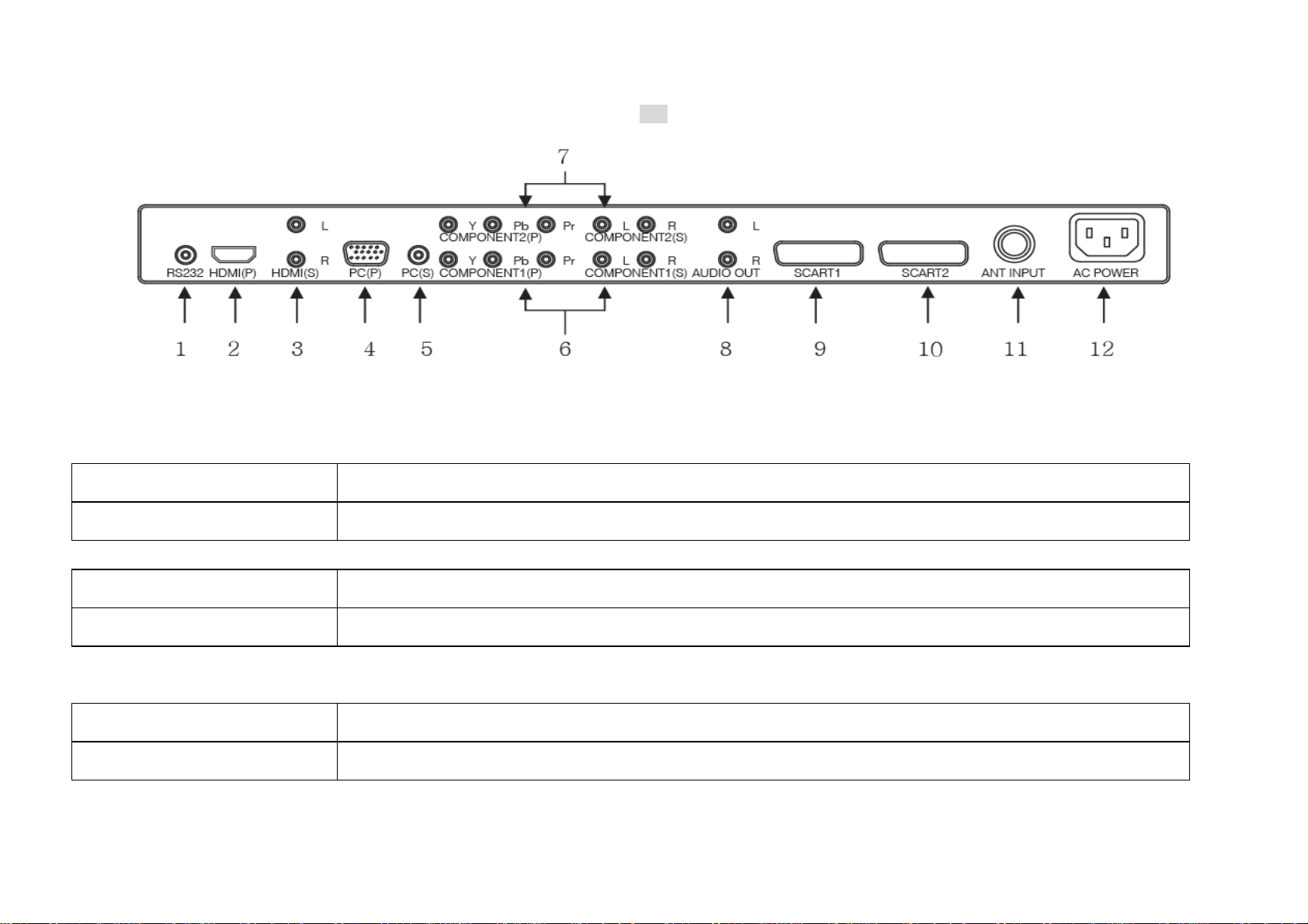
1-4-2. I/O Description.
1-5. Operation Environmental Conditions.
Temperature 0 to 50 °C (with forced-air cooling)
PAL
Humidity 20 to 40 °C to 80% RH (without condensation)
1-6. Storage Environmental Conditions.
Temperature -20 to 60 °C
Humidity 10 to 70% RH (without condensation)
1-7. Mechanical Test Conditions.
Vibration (operating) 4.9m/s2 (0.5 G), 10 to 100 Hz, 3 directions, 10 minutes each
Vibration (non-operating) 4.9m/s2 (0.5 G), 10 to 100 Hz, 3 directions, 2 hours each
11
Page 12

2. Block Diagram.
2-1. Panel Block Diagram.
LG Panel
12
Page 13

2-2. Connector Layout
2-2-1 PAL & SECAM – SCART.
2-2-1-1 Main Board & Sub Board.
13
Page 14

3. Board Assembling.
3-1. Preparation.
Place a sheet over a flat table which can support the weight of LCD.①
<CAUTION>
The sheet must be clean, smooth and thick enough to reduce any impact which might occur while handling.
Lay down the unit with the rear cover facing up.②
14
Page 15

3-2. Board Assembly Diagram.
3-2-1 Harness Path Diagram. (PAL/SECAM).
Model
Panel
System
DLP-37D1
LG
PAL/SECAM
Q’ty
3
6
1
2
5
4
7
No Name Part Code
1
2
3
4
5
AD POWER
DD-L32ADP-40 1
12P*15P*300MM
LVDS
DD-L32LVD-41 1
30P*30P*300MM
INVERTER
DD-L37INR-40 1
12P*12P*400MM
INVERTER
DD-L37INL-40 1
12P*12P*4P*500MM
SPEAKER
DD-L32SPK-40 1
6P*LUG(A,B)*550MM
8
8
Assembly of ‘⑧ GND Harness Path’ consult 37 page.
6
14P*8P*6P*400mm*500mm
7
8
★ Attention.
1) Speaker Harness : RED Æ Left / White Æ Right
NOISE FILTER*2P+GND
KEY-IR
2P*350mm+GND
GND
200MM/400MM
DDL32KEYIR40 1
DD-L32MPN-20
DD-L32MPN-30
DDL32GND—40
DDL37GND--40
1
2
15
Page 16

Assembly of ‘⑧ GND Harness Path’
1. GND Harness(IR PCB to Panel BKT)
No Name Part Code
Q’ty
GND HARNESS
(IR PCB to Panel BKT) 1
DDL32GND—40 1
200MM
GND HARNESS
(IR Knob to Panel BKT) 2
400MM
DDL37GND—40 1
2. GND Harness(IR PCB to Panel BKT)
As an above image, for protecting PCB from static electricity, GND Harness should be connected between Panel BKT and IR PCB, IR Knob, respectively.
16
Page 17

3- 3. Board Sort.
3-3-1 How to sort Main PCB according to Panel Maker (LG or Samsung).
Main PCB for LG Panel
Chip was soldered on FB49, R574 of Main PCB for LG Panel.
17
Page 18

3-3-2 How to sort Tuner PCB according to System (PAL, ATSC, 3-System).
Tuner PCB for PAL System Tuner PCB for ATSC System
Tuner PCB for 3-System System Tuner PCB for 2 RCA
18
Page 19

4. Set Assembly.
4-1. Assembly Diagram.
4-1-1. Assemblage of Front Parts.
Step 1
Put down the front
Step 2
Assemble Speaker Grill & elbow
Use the Screw No.1 (4ea)
No.2 (14ea)
Step1
Step2
`
Step3
Step 3
Assemble L/R Speaker Unit
Use the Screw No.1 (8ea)
Page 20

4-1-2. Assemblage of IR.
Step 1
Assemble Window IR
Step 2
Assemble Window Plate
Step 3
Assemble Knob Stand by
Use the Screw No.1(4ea)
Step1 Step2
`
Step3 Step4
Step 4
Assemble Key IR
Use the Screw No. 1(2ea)
Page 21

4-1-3. Sub Panel Assembly.
Step 1
Open the Box & Put down the Panel
Assemble Panel Cover
Use the Screw No.3(8ea)
Step 2
Step1
Step2
Assemble Stand Support
Use the Screw No.2 (2ea)
Page 22

4-1-4. Assembly of Panel Ass’y.
Step 1
Assemble Panel Ass’y
Use the Screw No.2 (9ea)
-Top 4ea
-Bottom 5ea
Step1
Page 23

4-1-5. Assemblage of Board.
Step 1
Assemble Main Board & Retainer Coil(1ea)
Use the Screw No.4(12ea)
Hold the LVDS Cable Use the Retainer Coil
Step 2
Assemble Noise filter
-Assemble Earth bolt
Use the Screw No. 5(1ea)
-Assemble Noise filter
Use the Screw No. 6(2ea)
-Assemble Cable (Bottom Position Green)
Step1
Step2
Page 24

4-1-6. Assemblage of PCB Cover.
Step 1
Assemble PCB Cover
Use the Screw No.2 (14a),
Step 2
Assemble PCB Cover
Use the Screw No.3 (1ea) ,
No.7 (7ea) ,
No.8 (2ea)
Step1
Step2
Page 25

4-1-7. Assemblage of Rear Cover.
Step 1
Assemble Knob Control
Use the Screw No.1(6ea)
Step 2
Assemble Rear Cover
Use the Screw No. 2 (14ea)
Step1
Step2
Page 26

4-1-8. Assemblage of Stand.
Step 1
Assemble Stand Cover
Step 2
Assemble Stand Base
Use the Screw No.9 (4ea)
No.10 (4ea)
Step 3
Assemble Rubber
Step 4
Assemble Stand Ass’y
Step1 Step2
Step3 Step4
Use the Screw No.11 (6ea)
Page 27

4-2. Screw Part Name.
NO. IMAGE SORT NAME / SPEC
No.1
No.2
No.3
No.4
No.5
Taptite + Washer + Panhead TWP 3*6 Black
Taptite + Panhead T/S-2B+4*10Ni
Machine Screw + Washer+ Panhead WP+4*8 Black
Machine Screw + Plain Washer +
SW/PW BP+3*8
Spring Washer
Machine Screw + Panhead + External
T/T CT BB+4*10
Teeth Washer
No.6
No.7
Machine Screw + Panhead BP+3*10
Taptite + Bindhead T/T-BB+3*8
Page 28

No.8
Hexa Nut HEXA NUT
No.10
No.11
No.9
Taptite + Panhead T/T-BP+4*8
Machine Screw OVEL + M4*10
Machine Screw + Trusshead T+4*16 Black
Page 29

4-3. Part List.
No. Part Code Part Name Mat./Spec Q’ty
DL3760M150A1 CABINET FRONT-378-DW MOLD/ABS/1TONE 1EA
1
DL3760M150A2 CABINET FRONT-378-DW MOLD/ABS/2TONE 1EA
2
DL3760M160BA COVER REAR-378-DW MOLD/ABS/BLACK 1EA
3
DL3760M1700A1 SPEAKER GRILL-60-DW MOLD/ABS/BLACK 1EA
4
DL3760M1700A2 SPEAKER GRILL-60-DW MOLD/ABS/SILVER 1EA
5
DL3280M181BA KNOB CONTROL-3280 DW MOLD/ABS/BLACK 1EA
6
DP4260M112A SPEAKER ELBOW-4260 MOLD/ABS/2.0T/BLACK 2EA
7
DP4260M113A SPEAKER ELBOW-4260 MOLD/ABS/2.0T/SILVER 2EA
8
DL3280M170A1 COVER STAND-326-DW MOLD/ABS/BLACK 1EA
9
DL3280M170A2 COVER STAND-326-DW MOLD/ABS/SILVER 1EA
10
DL3760P303A PANEL COVER-PAL PRESS/EGI/1.2T/PAL 1EA
11
DL3760P313A PCB COVER-PAL PRESS/EGI/1.2T/PAL 1EA
12
DL3760P370A PANEL BRACKET-3760 PRESS/EGI/1.6T 6EA
13
DL3760M220A DECO FRONT MOLD/ACRYL/2.0T 1EA
14
DL3280M190CA KNOB STAND BY-3280 MOLD/ABS/Cr 1EA
15
DL3280M180SA KNOB CONTROL-3280 MOLD/ABS/3.0t 1EA
16
DL3280M200A WINDOW IR-3280 MOLD/PA 1EA
17
DL3280M210A WINDOW PLATE MOLD/Acryl/1.2T 1EA
18
DL328TB614B AV LABEL-PAL
19
DL3760P300A STAND SUPPORT-3760 PRESS/EGI/2.0T 1EA
20
DL3280P330A STAND BRACKET-3280 PRESS/EGI/4.0T 1EA
21
DL3280P340A STAND BRACKET B-3760 PRESS/EGI/4.0T 1EA
22
DL3280P320A STAND BASE-3280 PRESS/EGI/3.0T 1EA
23
DL3280M170SA STAND COVER-3280 MOLD/ABS/3.0t 1EA
24
LD-3290/AV/218PAL
1EA
Page 30

5. Trouble Shooting.
This can eliminate misjudgments as defects due to user’s improper usage, by providing possible defective symptoms, checking the causes of defects, and repair instructions. Below images shows
a simple drawing of the LCD(fig.1). Following description is based on fig.1.
Defect description will be categorized as follows.
Power failure①
Key, IR Control Failure②
Picture Failure③
Sound F④ ailure
Application Failure⑤
Fig .1
Page 31

5-1. Power Failure.
< SYMPTOM >
1. LED is not lit at the Standby mode (If Power is working properly, LED color should be Red at Standby mode.).
2. The set’s Power & LED does not turn on (If Power is working properly, LED color should be Blue at Operation mode.).
3. Power shuts off within 10 seconds after the power is turned on.
4. Power shuts off in operation.
Step Check Point OK NG
1 Check the cable connections. Next step. Connect & Replace.
2 Replace the KEY,LED-IR B/D temporarily. Replace the KEY,LED-IR B/D. Next step.
3 Replace the ATSC B/D.( ONLY ATSC SYSTEM)
4 Replace the AV B/D. Next step.
5 Replace the AD B/D. Next step.
6 Replace the POWER B/D.
Next step.
5-2. KEY, LED-IR Control Failure.
< SYMPTOM >
1. Key or LED-IR (Remote) Control Failure.
Step Check Point OK NG
1 Check the cable connections. Next step. Connect & Replace.
2 Replace the KEY, LED-IR B/D temporarily. Replace the KEY, LED-IR B/D. Next step.
3 Replace the ATSC B/D.( ONLY ATSC SYSTEM)
Next step.
4 Replace the AV B/D. Next step.
5 Replace the AD B/D. Next step.
Page 32

5-3. Picture Failure.
< SYMPTOM >
1. Nothing appears on screen but sound is working.
2. Brightness, Black Line or Black square.
3. ‘No Signal’ OSD is displayed on screen, or Picture is poor.
Check the input source, cable connection and output setting value for A/V device(DVD player, VCR, Settop Box…) before testing as described below.
Video mode is AUTO.
Step Check Point OK NG
1 Check the cable connections.
Especially check the cable (LVDS cable) connection between PANEL and AD BOARD.
2 Replace the ATSC B/D.( ONLY ATSC SYSTEM) Next step.
3 Replace the AV B/D. Next step.
4 Replace the AD B/D. Next step.
5 Replace the POWER B/D.
Next step. Connect & Replace
Page 33

5-4. Sound Failure.
< SYMPTOM >
1. There is no Sound in all modes (Picture appears but there is no sound in all modes.).
2. There is no Sound in a certain mode (But sound is working in other mode.) or sound quality is poor.
3. Sound System Checking Problem.
Check the input source, cable connection and output setting value for A/V device(DVD player, VCR, Settop Box…) before testing as described below.
Step Check Point OK NG
1 Check the cable connections. Next step. Connect & Replace
2 Replace the ATSC B/D.( ONLY ATSC SYSTEM) Next step.
3 Replace the AV B/D. Next step.
4 Replace the AD B/D. Next step.
5 Replace the POWER B/D.
5-5. Application Failure.
< SYMPTOM >
1. Channel Memory Problem.
Step Check Point OK NG
1 Check the Option with a service remote controller. Next step. Adjustment.
2 Check the Video mode with remote controller. Next step. Adjustment.
3 Replace the ATSC B/D.( ONLY ATSC SYSTEM) Next step.
4 Replace the AV B/D. Next step.
5 Replace the AD B/D. Next step.
6 Replace the POWER B/D.
2. Last memory Problem -> Replace the AD B/D.
3. Monitor-Out Problem -> Check the external device connected to the monitor out of the LCD and then replace the AV B/D.
4. Vibration Noise of LCD (This is not Sound noise but Mechanical Part’s vibration.)
-> Check the insulation sheet of Mechanical Part’s side
Page 34

6. Firmware Update Method.
6-1. Main Board Firmware Update.
4
1. Set Main Power off. (Pull out power cord from LCD TV.)
2. Insert Phone Jack using RS232 to stereo jack Cable below Fig. 1.
Fig. 1. Main Board Input Jack.
3. Double Click ‘Flash express_logo.exe’ in unzipped Firmware file below Fig. 2..
7
5
6
Fig.3. Firmware Update Program
4. After clicking ‘
5. After clicking ‘
6. If you turn on the LCD TV after clicking ‘
★ Attention.
1. If you could hardly make progress update, retry varying port after clicking ‘
’, assign directory saved ‘Flesch_logo.exe’ in PC
’, assign ‘WARE3_boot.inf’.
’, you make progress firmware update.
’ of number 7
on Fig. 2
2. After firmware update finished, you must confirm firmware version and do factory reset.
Fig. 2. Firmware program files in directory.
Æ Method to enter factory mode.
Push 1ÆMuteÆSelect/EnterÆMute
key on remote controller
 Loading...