


Service Manual
B3.3 Diesel Engine
Lift Trucks
D20S-3(B3.3), D25S-3(B3.3), D30S-3(B3.3),
D32S-3(B3.3), D33S-3(B3.3)
Skid Steer Loaders
450/450Plus, 460/460Plus
SB4135E00
Jan. 2004


Important Safety Information
Most accidents involving product operation, maintenance and repair are caused by failure to observe basic safety
rules or precautions. An accident can often be avoided by recognizing potentially hazardous situations before an
accident occurs. A person must be alert to potential hazards. This person should also have the necessary training,
skills and tools to perform these functions properly.
Read and understand all safety precautions and warnings before operating or performing lubrication,
maintenance and repair on this product.
Basic safety precautions are listed in the “Safety” section or the Service or Technical Manual. Additional safety
precautions are listed in the “Safety” section of the owner/operation/maintenance publication.
Specific safety warnings for all these publications are provided in the description of operations where hazards exist.
WARNING labels have also been put on the product to provide instructions and to identify specific hazards. If
these hazard warnings are not heeded, bodily injury or death could occur to you or other persons. Warnings in this
publication and on the product labels are identified by the following symbol.
Improper operation, lubrication, maintenance or repair of this product can be dangerous and could result
in injury or death.
Do not operate or perform any lubrication, maintenance or repair on this product, until you have read and
understood the operation, lubrication, maintenance and repair information.
Operations that may cause product damage are identified by NOTICE labels on the product and in this publication.
DAEWOO cannot anticipate every possible circumstance that might involve a potential hazard. The warnings in
this publication and on the product are therefore not all inclusive. If a tool, procedure, work method or operating
technique not specifically recommended by DAEWOO is used, you must satisfy yourself that it is safe for you and
others. You should also ensure that the product will not be damaged or made unsafe by the operation, lubrication,
maintenance or repair procedures you choose.
The information, specifications, and illustrations in this publication are on the basis of information available at the
time it was written. The specifications, torques, pressures, measurements, adjustments, illustrations, and other
items can change at any time. These changes can affect the service given to the product.
Obtain the complete and most current information before starting any job. DAEWOO dealers have the most
current information available.
W
ARNIN
G
1


Index
Introduction
About the Manual................................................... 4
How to Use the Manual ......................................... 4
Illustrations............................................................. 6
Symbols ................................................................. 5
Engine Identification
Engine Diagrams ................................................... 9
Engine Views....................................................... 9
Engine Identification .............................................. 7
Engine Dataplate ................................................. 7
Specifications......................................................... 8
Troubleshooting Symptoms
Procedures and Techniques .................................20
Troubleshooting Symptoms Charts.......................20
Coolant Contamination .......................................34
Coolant Loss.......................................................35
Coolant Temperature above Normal...................38
Engine Cranks But Will Not Start
(No Exhaust Smoke) ..........................................22
Engine Difficult to Start or Will Not Start
(Exhaust Smoke) (Continued) ............................24
Engine Difficult to Start or Will Not Start
(Exhaust Smoke) ................................................23
Engine Has Poor Respones ...............................25
Engine Power Output Low (Continued) ..............29
Engine Power Output Low..................................28
Engine Runs Rough or Misfires..........................27
Engine Stops During Operation ..........................26
Engine Vibration Excessive ................................41
Engine Will Not Crank or Cranks Slowly ............21
Excessive Exhaust (Black Smoke) .....................30
Excessive Noise (Continued) .............................40
Excessive Noise .................................................39
Fuel consumption Is Excessive ..........................33
Lubricating Oil Consumption Excessive .............31
Lubricating Oil Contaminated .............................32
Lubricating Oil Pressure Is Low..........................36
Oil Level Rises....................................................37
Complete Engine
Engine Testing
Complete Engine.................................................. 89
Measuring Compression Pressure..................... 89
Testing and Adjusting the Fan Belt Tansion ....... 91
Fuel System ......................................................... 92
Checking and Adjusting Fuel Injection Timing ... 92
Injector ................................................................. 95
Assembly ........................................................... 98
Disassembly....................................................... 97
Testing................................................................ 95
Lubricating System............................................. 100
Measuring Oil Pressure ................................... 100
Rocker Levers ...................................................... 87
Adjusting Valve Clearance ................................. 87
Specifications
Camshaft and Camshaft Bushing ...................... 105
Capscrew Markings and Torque Values - Metric 115
Capscrew Markings and Torque Values - U.S.
Customary.......................................................... 116
Capscrew Markings and Torque Values ............. 115
Connecting Rod, Piston Ring and Piston Pin..... 111
Crankshaft.......................................................... 106
Cylinder Block .................................................... 104
Cylinder Head .................................................... 103
Cylinder .............................................................. 109
Flywheel ............................................................. 108
Fraction, Decimal, Millimeter Conversions......... 117
Newton-Meter to Foot-Pound Conversion
Chart .................................................................. 118
Oil Pump ............................................................ 112
Pipe Plug Torque Values.................................... 118
Piston ................................................................. 110
Regulator Valve.................................................. 113
Rocker Arm Shaft, Push Rod and Tappets......... 102
Tap-Drill Chart - U.S. Customary and Metric ...... 119
Thermostat ......................................................... 114
Timing Gear........................................................ 107
Valves, Valve Guides, and Springs .................... 101
Weight and Measures - Conversion Factors...... 120
Special Tool
Special Tool List ................................................. 121
Complete Engine ..................................................42
Engine Assembly ................................................61
Engine Disassembly ...........................................42
Diesel Engine Index
3

About the Manual
This Troubleshooting and Repair Manual is intended to aid in determining the cause of engine-related problems
and to provide recommended repair procedures.
The material in this manual covers all Signature engines. The manual is divided into sections. Each section is
equivalent to a group used in Cummins filmcard system. Some sections contain reference numbers and
procedure numbers. Reference numbers provide general information, specifications, diagrams, and service tools
where applicable. Procedure numbers are used to identify and reference specific repair procedures for correcting
the problem.
This manual is designed so the troubleshooting trees are used to locate the cause of an engine problem. The
troubleshooting trees then direct the user to the correct repair procedure. The repair procedures within a section
are in numerical order. However, the repair steps within a given procedure are organized in the order the repair
must be performed, regardless of the numerical order of the steps. The user must use the Section Contents pages
or the Index at the back of the manual to locate specific topics when not using the troubleshooting trees.
How to Use the Manual
This manual is organized to provide an easy flow from problem identification to problem correction. A list of
troubleshooting symptoms containing the most common engine problems is in the Troubleshooting Symptoms,
Section TS. The manual is designed to use the Troubleshooting Symptoms as a guide to locating the problem and
directing the end user to the correct procedure for making the repair. Complete the following steps to locate and
correct the problem.
(Step 1) Locate the symptom on the Section Contents pages of Section TS.
Reference to the page number where the Troubleshooting Symptom Tree is
found is made to the right of the symptom tree title.
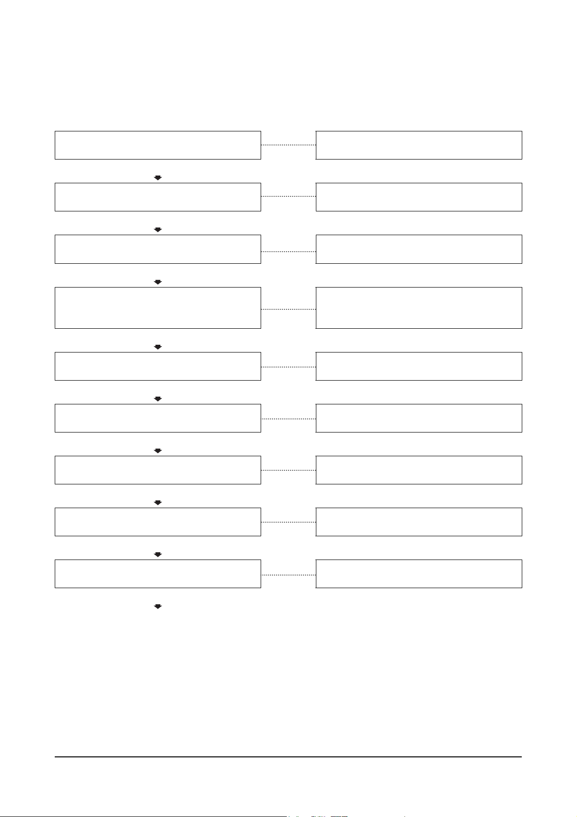
(Step 2) The left column of boxes in the Troubleshooting Symptom Charts indicates a
probable cause of the problem, starting at the top with the simplest and easiest to
repair, and continuing downward to the most difficult.
The right column of boxes provides a brief description of the corrective action
with a reference number to the correct procedure used to make the repair.
(Step 3)
(Step 4) The Troubleshooting Symptom Charts are based on the following assumptions:
Locate the probable cause in the left column; then turn to the procedure
referenced in the right column.
1. The engine has been installed according to the manufacturer's specifications.
2. The easiest repairs are done first.
3. "Generic" solutions cover problems with the most common applications and
original equipment manufacturer (OEM).
Diesel Engine Introduction
4
Symbols
The following symbols have been used in this manual to help communicate the intent of the instructions. When
one of the symbols appears, it conveys the meaning defined below:
WARNING – Serious personal injury or extensive property damage can result if the
CAUSION – Minor personal injury can result or a part, an assembly or the engine can be
warning instructions are not followed.
damaged if the Caution instructions are not followed.
Indicates a REMOVAL or DISASSEMBLY step.
Indicates an INSTALLATION or ASSEMBLY step.
INSPECTION is required.
CLEAN the part or assembly.
PERFORM a mechanical or time MEASUREMENT.
LUBRICATE the part or assembly.
Indicates that a WRENCH or TOOL SIZE will be given.
TIGHTEN to a specific torque
PERFORM an electrical MEASUREMENT.
Diesel Engine Introduction
Refer to another location in this manual or another publication for additional information.
The component weighs 23kg [50lb] or more. To avoid personal injury, use a hoist or get
assistance to lift the component.
5
Illustrations
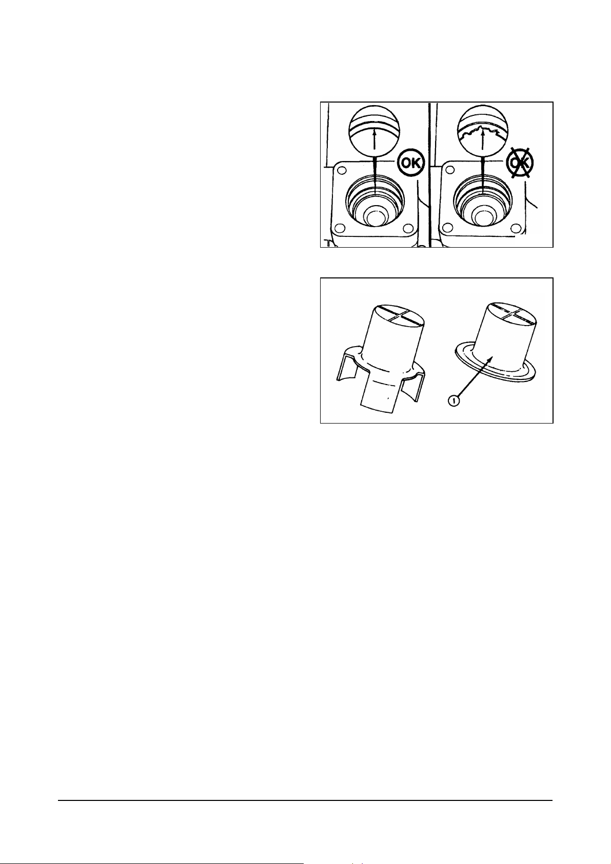
Some of the illustrations throughout this manual are
generic and will not look exactly like the engine or
parts used in your application. The illustrations can
contain symbols to indicate an action required and an
acceptable or not acceptable condition.
The illustrations are intended to show repair or
replacement procedures. The procedure will be the
same for all applications, although the illustration can
differ.
th8sesa
Ca8vagc
Diesel Engine Introduction
6
Engine Identification
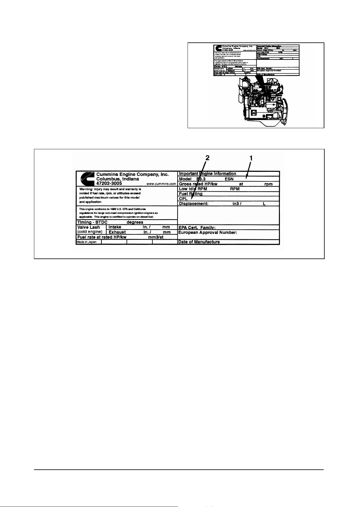
Engine Dataplate
The engine dataplate shows specific information
about the engine. The engine serial number (ESN)
and control parts list (CPL) provide information for
ordering parts and for service needs.
NOTE: The engine dataplate must not be changed
unless approved by Cummins Engine
Company, Inc.
00900248
00900249
Diesel Engine Engine Identification
7

Specifications
Performance D20/25/30/32/33S-3
Standard - SAEJ1995
Air Cleaner - without but with 3.0kPa intake restriction
Test Condition
Rated Power kW(PS) 43.4 (59) @ 2200 rpm 48.5 (65) @ 2600 rpm
Max Torque Nm(kgf-m) 202 (20.6) @ 1600 rpm 214 (21.8) @ 1600 rpm
Torque Rising
BSFC
General Engine Data Naturally Aspirated
Engine Weight (Dry) Less Flywheel and Electronics 245 kg [540 lb]
Compression Ratio 18.8
Bore 95 mm [3.74 in]
Stroke 115 mm [4.528 in]
Displacement 3.26 liters [199 in³]
Firing Order 1-2-4-3
Valve Clearance:
Rotation Viewed from the Front of the Engine Clockwise
Lubrication System Naturally Aspirated
Regulating Valve Opening Pressure 490 kPa [71 psi]
Lubricating Oil Capacity:
Lubricating Oil Pressure at Idle (Minimum Allowable) 69 kPa [10 psi]
Lubricating Oil Pressure at Rated (Minimum Allowable) 245 kPa [35 psi]
Oil Filter Differential Pressure to Open Bypass Valve 98 kPa [14 psi]
Number of liters [qt] from Low to High 1.5 liters [1.6 qt]
Cooling System Naturally Aspirated
Coolant Capacity (Engine Only ) 4.5 liters [4.75 qt]
Standard Modulating Thermostat
Range:
Maximum Pressure Cap @ Sea Level 50 kPa [7 psi]
Air Induction System Naturally Aspirated
Maximum Allowable Intake Restriction at Rated Speed and
Load with Dirty Filter Element
Exhaust System Naturally Aspirated
Maximum Allowable Exhaust Restriction at Rated Speed and
Load with Dirty Filter Element
Fuel System Naturally Aspirated
Maximum Allowable Restriction to the Fuel Transfer Pump
or Filter Head Must Not Exceed
Maximum Allowable Return Line Restriction Must Not
Exceed
Inlet Pressure to the Injection Pump Range 0.00 kPa [0.00 psi] to 39.0 kPa [5.00 psi]
Electrical System Naturally Aspirated
Minimum Recommended Battery
Capacity with Light Accessories*:
Minimum Recommended Battery
Capacity with Heavy
Accessories**:
Maximum Allowable Resistance
of the Starting Circuit:
*Typical light accessories include: Alternator, small steering pump, and disengaged clutch.
**Typical heavy accessories include: Hydraulic pump and torque converter.
Muffler - without but with 10.0kPa exhaust restriction
Alternator - without
Fan - without
7.4 % for 2200rpm rating 20.0% for 2600rpm rating
@Rated Power g/kWh 227 @2200rpm 236 @ 2600rpm
@Max Torque g/kWh 219 @1600rpm 226 @ 1600rpm
Intake
Exhaust
Total System
Standard Oil Pan Only
Start
Fully Open
12-VDC Starter 550 CCA
12-VDC Starter 730 CCA
12-VDC Starter 0.0012 ohms
7.5 liters [8.0 qt] 8.0 liters [8.5 qt]
0.35 mm [0.014 in]
0.50 mm [0.020 in]
7.0 liters [7.4 qt]
82° C [180° F]
95° C [203° F]
762 mm H2O
[30 in H2O]
190.5 mm Hg
450/450Plus,460/460Plus
75 mm Hg
[3 in Hg]
75 mm Hg
[3 in Hg]
[7.5 in Hg]
Diesel Engine Engine Identification
8
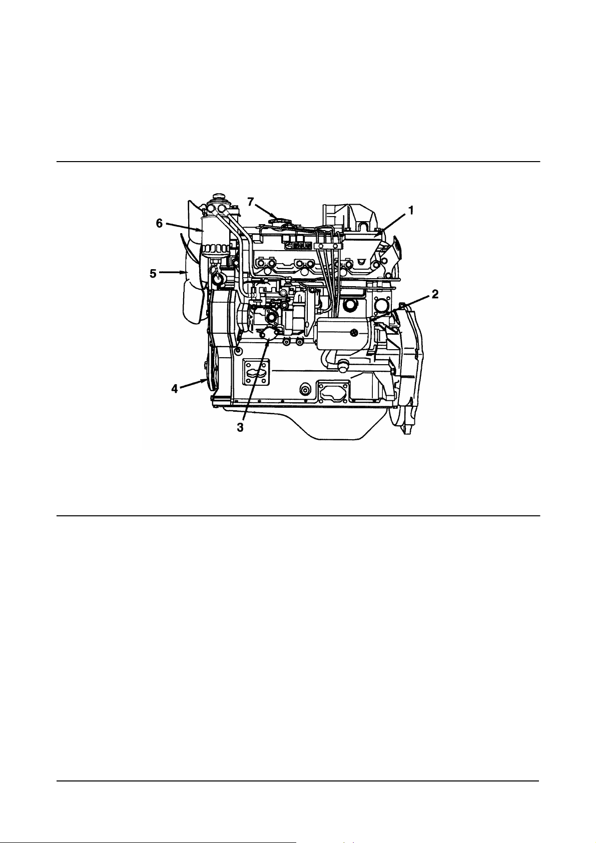
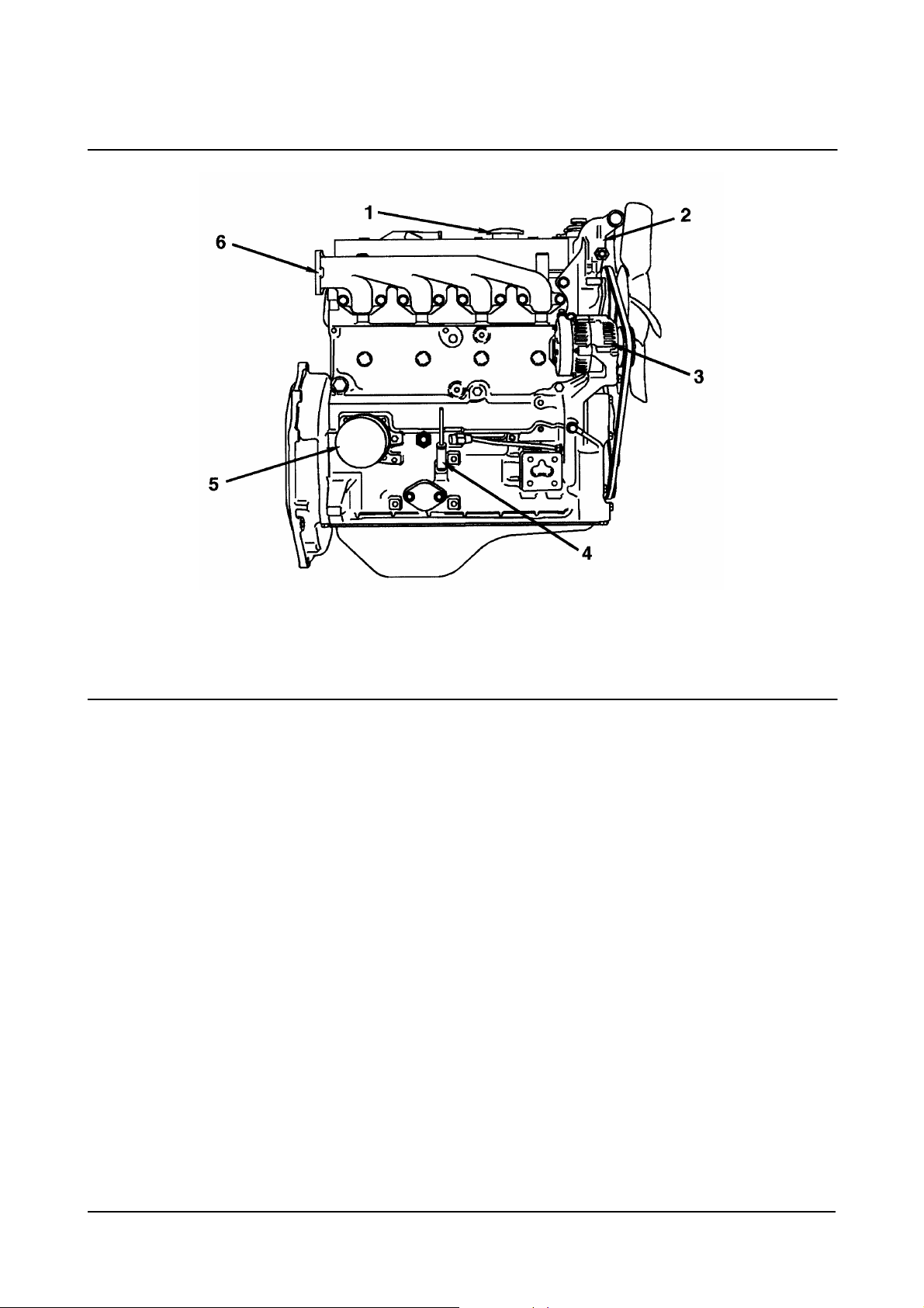
Engine Diagrams
Engine Views
The following illustrations show the locations of the major external engine components, filters, and other service
and maintenance points. Some external components will be at different locations for different engine models.
1. Intake Manifold
2. Starting Motor
3. Fuel Injection Pump
4. Crankshaft Pulley
Intake Side
(Naturally Aspirated)
00900138
5. Fan
6. Fuel Filter
7. Oil Fill Cap.
Diesel Engine Engine Identification
9
1. Oil Fill Cap
2. Thermostat Housing
3. Alternator
Exhaust Side
(Naturally Aspirated)
00900139
4. Dipstick
5. Oil Filter
6. Exhaust Manifold.
Diesel Engine Engine Identification
10
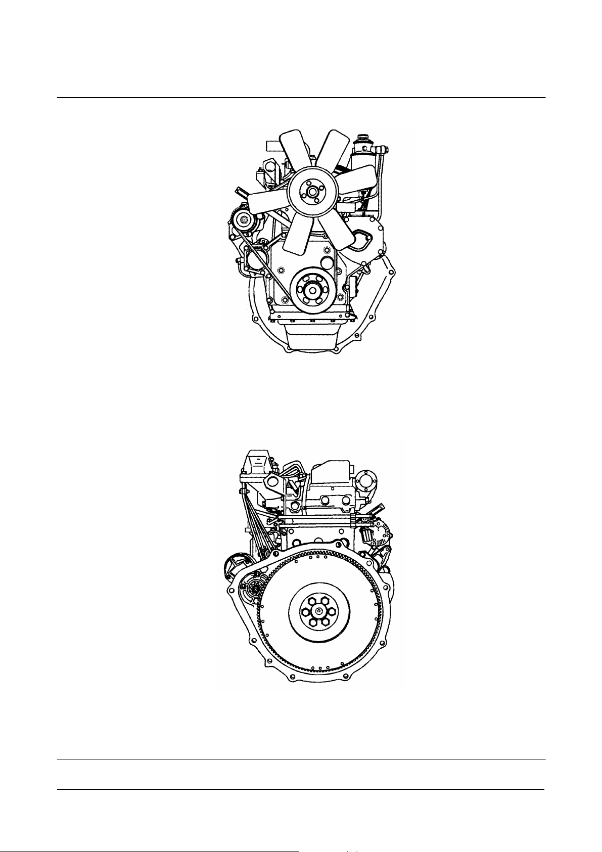
Front View
(Naturally Aspirated)
00900140
Rear View
(Naturally Aspirated)
00900141
Diesel Engine Engine Identification
11
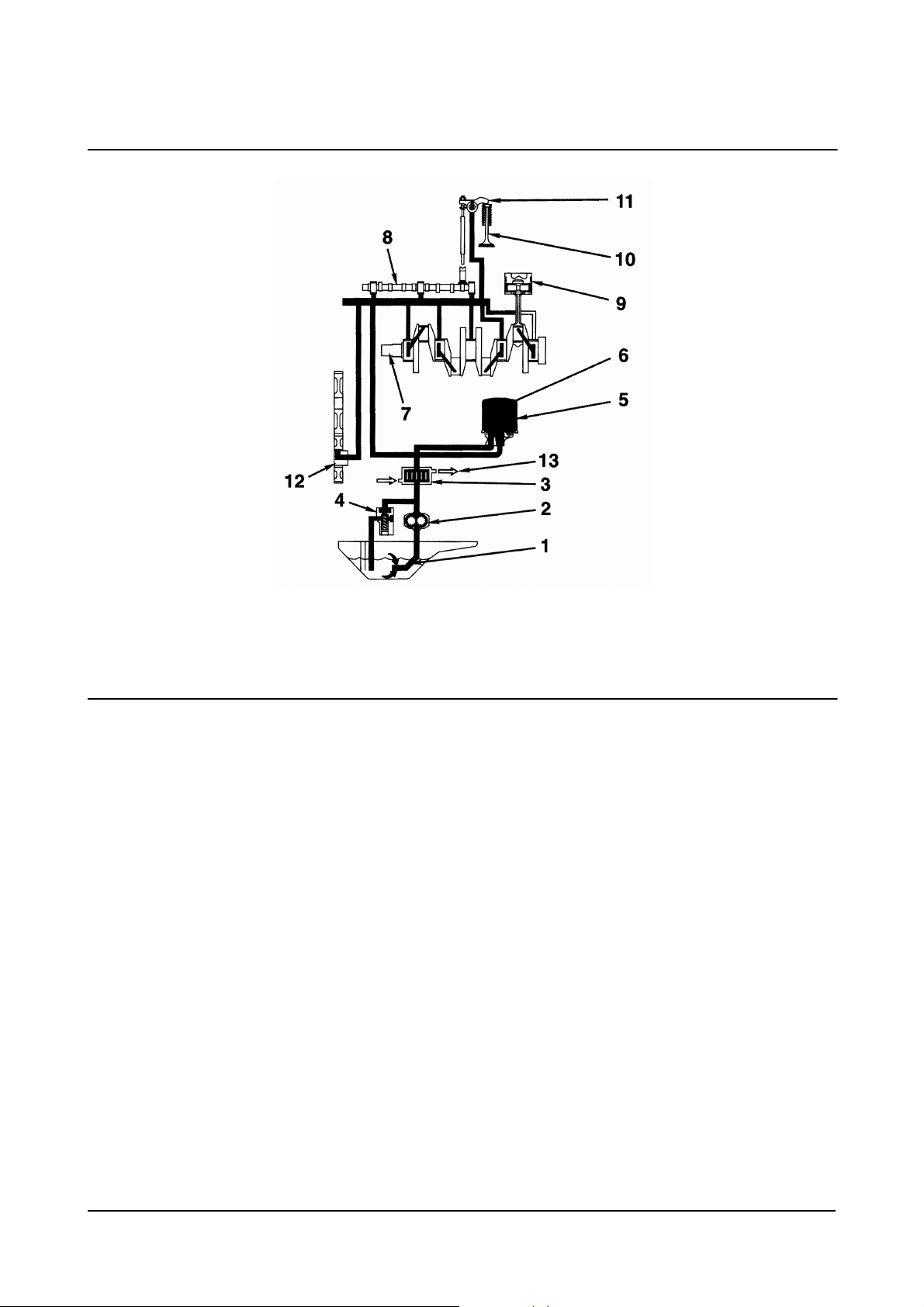
1. Oil Strainer
2. Oil Pump
3. Oil Cooler (Optional)
4. Regulator Valve
5. Oil Filter
6. Safety Valve
7. Crankshaft
Exhaust Side
(Naturally Aspirated)
00900146
8. Camshaft
9. Piston
10. Intake and Exhaust Valve
11. Rocker Arm
12. Timing Gear
13. Cooling Water.
Diesel Engine Engine Identification
12
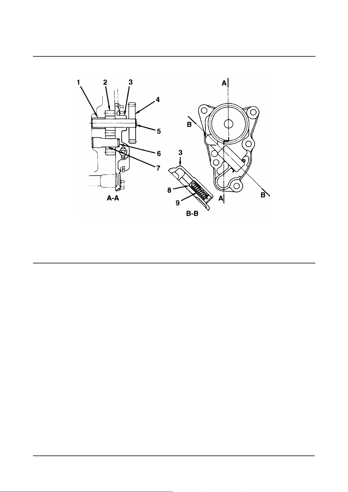
1. Bushing
2. Gear Drive (number of teeth: 7)
3. Pump cover
4. Oil Pump Drive Gear (number of teeth: 22)
5. Driveshaft
6. Drivenshaft
7. Driven Gear (number of teeth: 7)
Oil Pump
00900148
8. Regulator Valve
9. Valve Spring.
Oil pump
• Type: Gear Type
• Pump Speed: Engine Speed x 1.182.
Regulator Valve
• Set Pressure: 490 ± 50kPa [71 ± 7psi].
Diesel Engine Engine Identification
13
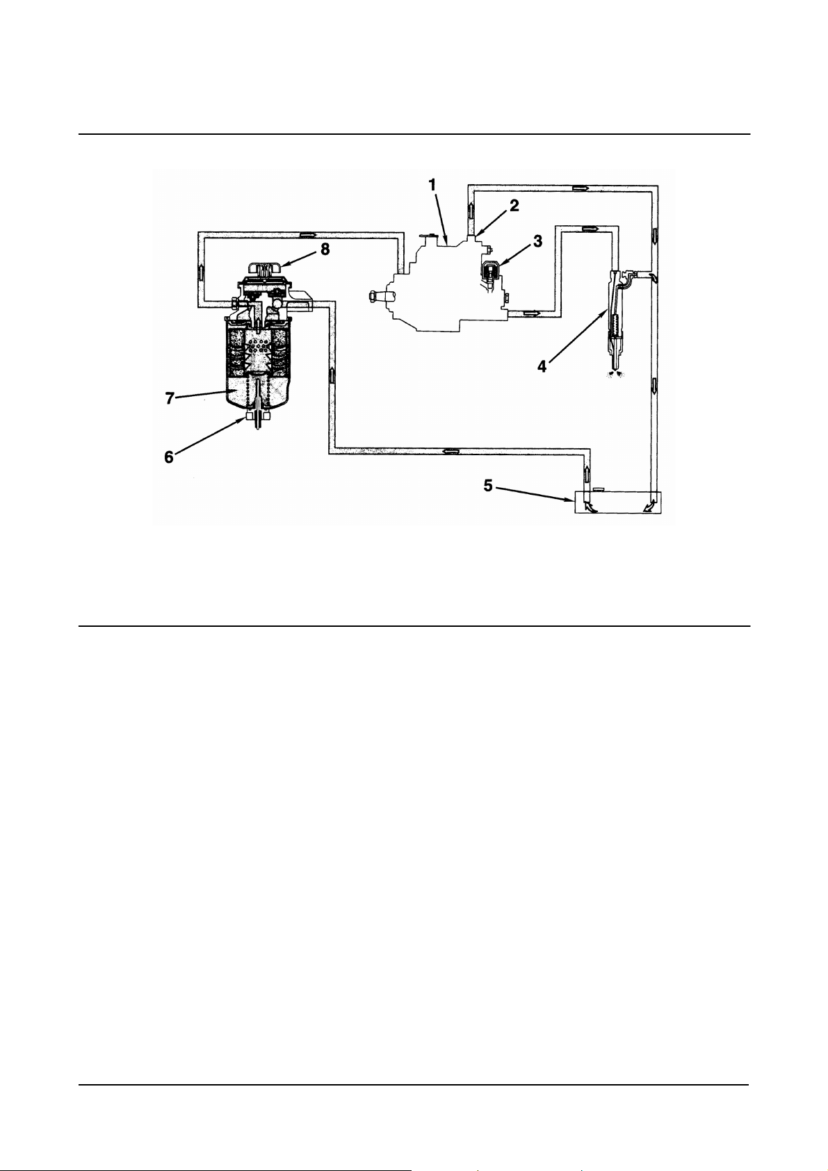
1. Fuel Injection Pump
2. Overflow Valve
3. Fuel Solenoid
4. Fuel Injection Nozzle
Fuel System
00900149
5. Fuel Tank
6. Water-in-Fuel Sensor (WIF)
7. Fuel Filter
8. Hand Priming Pump.
Diesel Engine Engine Identification
14
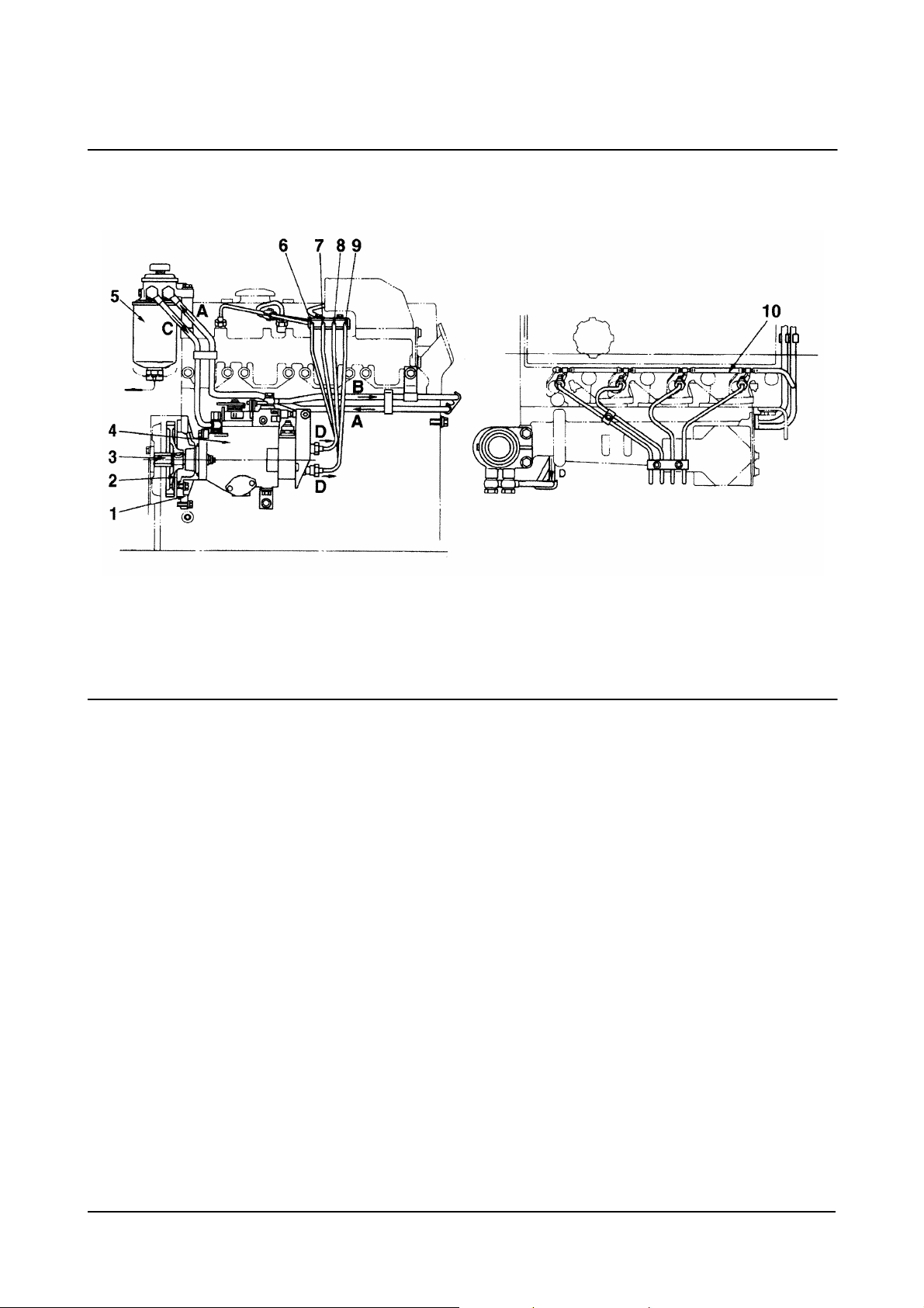
1. Pump Holder
2. Fuel Injection Pump Drive Gear
(number of teeth: 52)
3. Drive Shaft
4. Fuel Injection Pump (Body)
5. Fuel Filter
6. Fuel Injection Pipe (No. 1)
7. Fuel Injection Pipe (No. 2)
8. Fuel Injection Pipe (No. 3)
9. Fuel Injection Pipe (No. 4)
10. Spill Tube
Fuel Injection Pump
00900150
A. Fuel Inlet (from Fuel Tank)
B. To. Fuel Tank
C. To Fuel Injection Pump
D. To Fuel Injection Nozzle.
Fuel Injection Pump
• Maker: Zexel
• Type: VE
• Lubrication Method: Forced Lubrication with Fuel
Governor
• Type: Mechanical, All-speed Type.
Diesel Engine Engine Identification
15
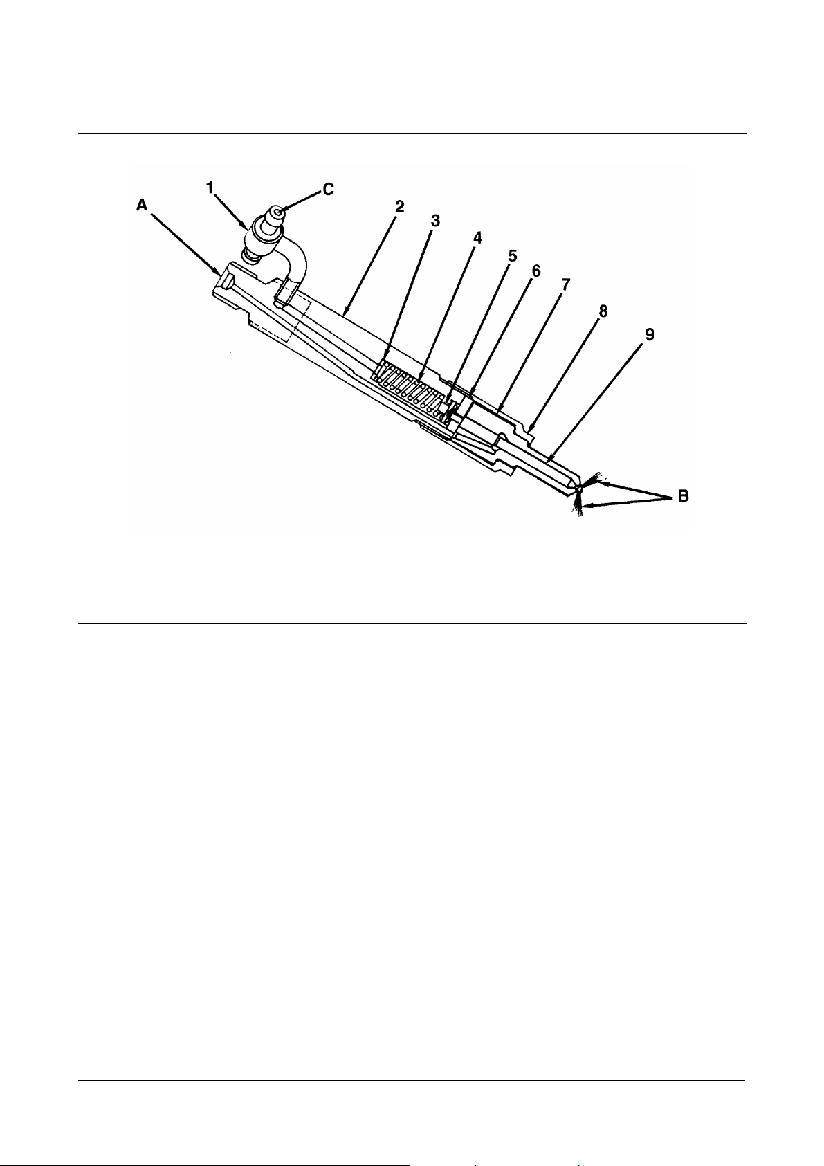
1. Fuel Drain Line Connector
2. Nozzle Holder
3. Adjusting Shim
4. Nozzle spring
5. Spring seat
6. Intermadiate Plate
7. Nozzle Body
8. Retaining Nut
9. Needle.
Fuel Injection Nozzle
00900151
A. Fuel Inlet (from injection pump)
B. Fuel Injection (to cylinder)
C. Fuel Return (to fuel tank).
Fuel Injection Nozzle
• Maker: Zexel
• Injection Pressure: 40 MPa
• Adjustment of Injection Pressure: By Shim.
Diesel Engine Engine Identification
16
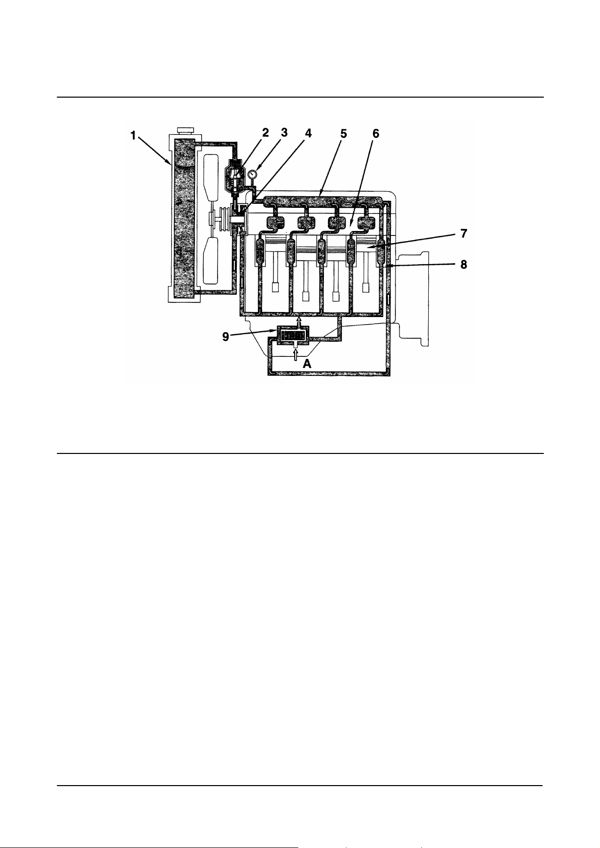
1. Radiator
2. Thermostat
3. Water Temperature Gauge
4. Water Pump
5. Water Manifold
Cooling System
00900147
6. Cylinder Head
7. Piston
8. Cylinder Block
9. Oil Cooler (optional).
A. From Oil Pump (oil).
Diesel Engine Engine Identification
17
1. Filtered Air
2. Intake Manifold
3. Intake Valve Port.
Air Intake System
00900227
Diesel Engine Engine Identification
18
1. Exhaust Valve Port
2. Exhaust Manifold
Exhaust System
00900232
Diesel Engine Engine Identification
19

Procedures and Techniques
A thorough analysis of the customer's complaint is the key to successful troubleshooting. The more information
known about a complaint, the faster and easier the problem can be solved.
The Troubleshooting Symptom Charts are organized so that a problem can be located and corrected by doing the
easiest and most logical things first. Complete all steps in the sequence shown from top to bottom.
It is not possible to include all the solutions to problems that can occur; however, these charts are designed to
stimulate a thought process that will lead to the cause and correction of the problem.
Follow these basic troubleshooting steps:
• Get all the facts concerning the complaint
• Analyze the problem thoroughly
• Relate the symptoms to the basic engine systems and components
• Consider any recent maintenance or repair action that can relate to the complaint
• Double-check before beginning any disassembly
• Solve the problem by using the symptom charts and doing the easiest things first
• Determine the cause of the problem and make a thorough repair
• After repairs have been made, operate the engine to make sure the cause of the complaint has been
corrected
Troubleshooting Symptoms Charts
Use the charts on the following pages of this section to aid in diagnosing specific engine symptoms. Read each
row of blocks from top to bottom. Follow through the chart to identify the corrective action.
Diesel Engine Troubleshooting Symptoms
20
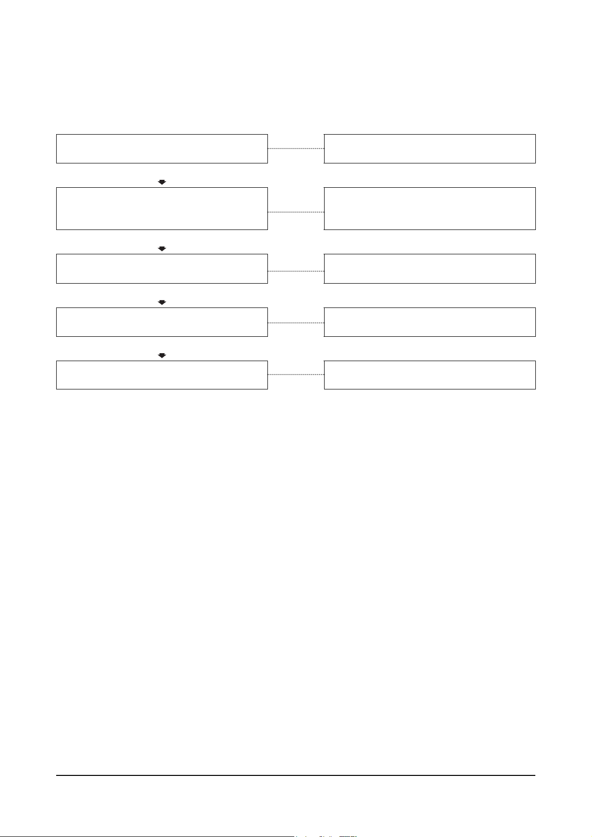
Engine Will Not Crank or Cranks Slowly
This is symptom tree T-002.
Cause Correction
Defective wiring of starting circuit
OK
Specific gravity of battery electrolytr is low, or
Battery voltage is low
OK
Staring motor is malfunctioning
Troubleshoot and repair starting circuit wiring
including relays and switches.
Check the alternator. If the alternator checks
Out, replace the battery.
Replace the staring motor.
OK
Ring gear tooth surface is chipped or damaged
Replace ring gear.
Diesel Engine Troubleshooting Symptoms
21
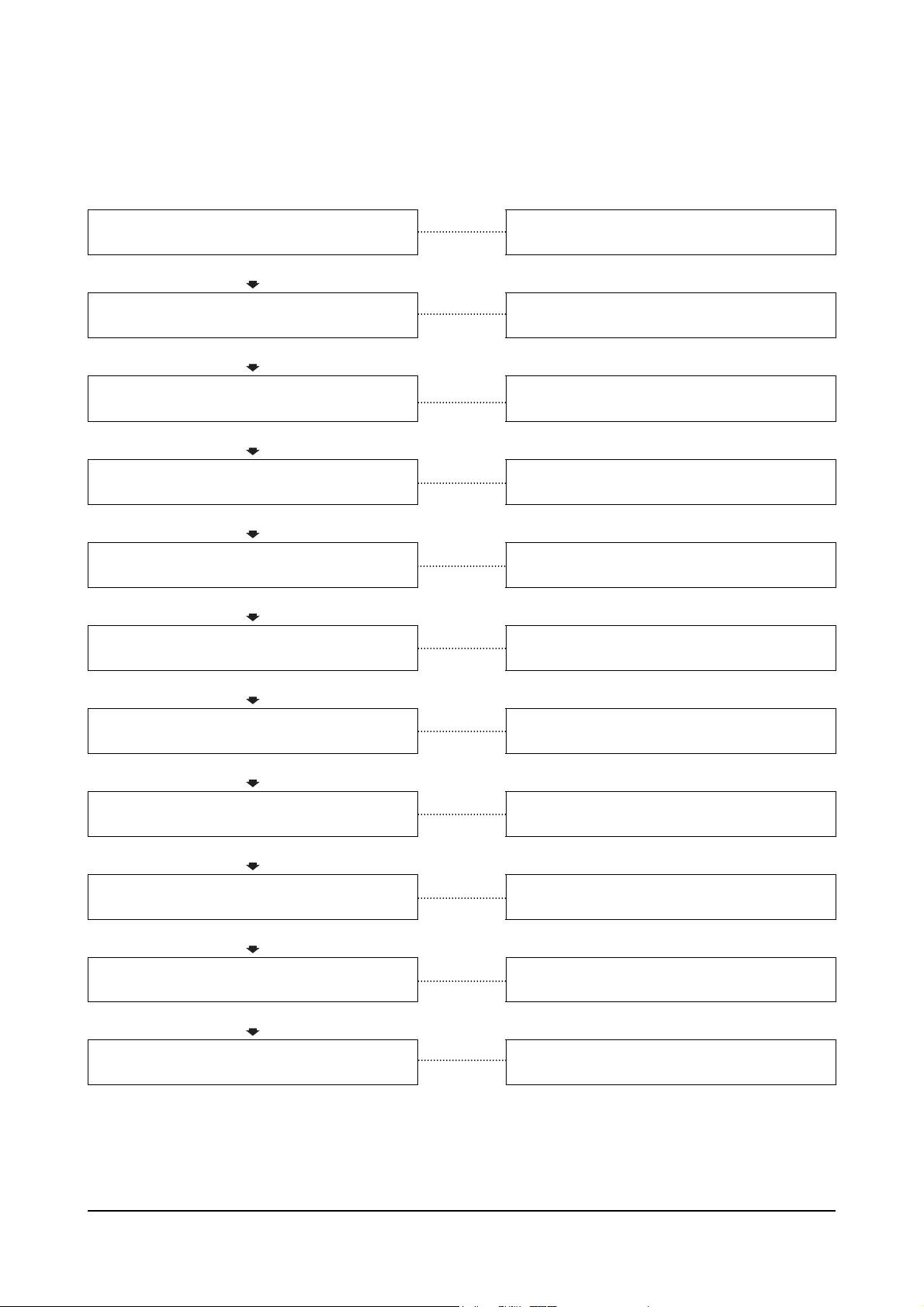
Engine Cranks But Will Not Start (No Exhaust Smoke)
This is symptom tree T-003.
Cause Correction
Fuel level low in the tank
OK
Improper fuel is being used
OK
Clogged fuel tank air breather hole
Fill the supply tank.
Drain fuel and replace with correct fuel.
Clean the fuel tank breather.
OK
Engine does start when voltage is applied to
the fuel cut solenoid valve
OK
Engine does not start when voltage is applied
to the fuel cut solenoid valve
OK
Clogged prefilter
OK
Clogged fuel filter or strainer
OK
Clogged or leaking fuel piping
OK
Feed pump is damaged or seized
OK
Injector are plugged
OK
damaged
Injection pump driveshaft or driveshaft key is
Troubleshoot and repair the circuit wiring.
Replace the fuel cut solenoid valve.
Clean the prefilter.
Clean or replace the fuel filter or strainer.
Clean and repair the fuel piping.
Replace the feed pump.
Replace the injectors.
Repair or replace the injection pump.
Diesel Engine Troubleshooting Symptoms
22

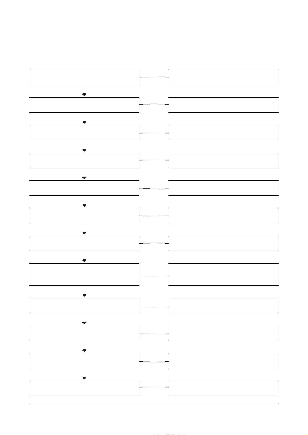
Engine Difficult to Start or Will Not Start (Exhaust Smoke)
This is symptom tree T-004.
Cause Correction
Starting aid malfunctioning or heater mount
Does not become warm
OK
Speed: 150 rpm)
OK
Improper fuel is being used
Crank speed is too slow (minimum crank
Replace the starting aid.
Verify drive units are not engaged. Check the
Battery and recharge or replace.
Drain fuel and replace with correct fuel.
OK
Clogged air cleaner element
OK
Clogged prefilter
OK
Clogged fuel filter or strainer
OK
Leakage, clogging, air in fuel system
OK
Injection pump timing is incorrect
OK
(Continued)
Clean or replace the air cleaner element.
Clean the prefilter.
Clean or replace the fuel filter or strainer.
Repair and clean the fuel filter or strainer.
Retime the injection pump.
Diesel Engine Troubleshooting Symptoms
23
Engine Difficult to Start or Will Not Start (Exhaust Smoke) (Continued)
Cause Correction
Overhead adjustments are not correct
OK
Overhead components are damaged
OK
Defective or clogged injection nozzle
OK
Injection pump is malfunctioning
OK
Worn piston ring or cylinder resulting in low
compression
Measure and adjust the overhead settings.
Inspect the rocker levers, rocker shafs, and
valve for excessive damage. Replace as
necessary.
Replace the defective or clogged injection
nozzle
Repair or replace the injection pump.
Replace the worn piston ring or cylinder.
Diesel Engine Troubleshooting Symptoms
24
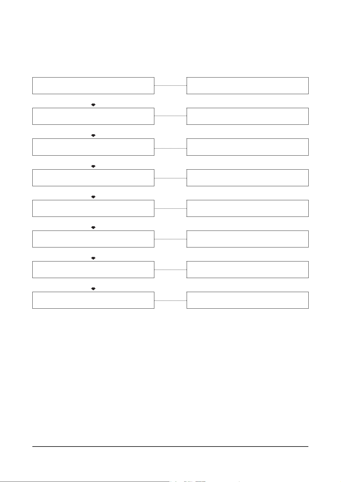
Engine Has Poor Respones
This is symptom tree T-005.
Cause Correction
Clogged air cleaner element
OK
Clogged fuel tank air breather hole
OK
Clogged prefilter
Clean or replace the air cleaner element
Clean the fuel tank breather.
Clean or replace the fuel filter or strainer.
OK
Clogged fuel filter or strainer
OK
Clogged or leaking fuel piping
OK
Overhead adjustments are not correct
OK
Resulting in low compression
OK
Turbocharger does not rotate freely
OK
Defective or clogged injection nozzle
OK
Injection pump is malfunctioning
Defective contact of valve or valve seat
Clean and repair the fuel piping
Clean and adjust the overhead settings.
Measure and adjust the overhead settings.
Replace the cylinder head.
Replace the turbocharger.
Replace the defective or clogged injection
nozzle.
Repair or replace the injection pump.
OK
Worn piston ring or cylinder resulting in low
Compression
Diesel Engine Troubleshooting Symptoms
25
Replace the worn piston ring or cylinder.
Engine Stops During Operation
This is symptom tree T-006.
Cause Correction
Chassis powertrain is damaged or overloaded
OK
Fuel level low in the tank
OK
Clogged fuel tank air breather hole
Refer to the OEM’s service manuals.
Fill the supply tank.
Clean the fuel tank breather.
OK
Clogged prefilter
OK
Clogged fuel filter or strainer
OK
Clogged or leaking fuel piping
OK
Feed pump piston is damaged or seized
OK
Overhead components are damaged
OK
Injection pump is malfunctioning
OK
Gear train damaged or seized
OK
Piston or connecting rod is damaged
OK
Crankshaft bearing is damaged
Clean the prefilter.
Clean and or replace the fuel filter or strainer.
Clean and repair the fuel piping.
Replace the feed pump.
Inspect the rocker levers, rocker shafts, and
valves for excessive damage. Replace as
necessary.
Replace the injection pump.
Refer to OEM’s service manuals.
Replace damaged piston or connecting rod.
Replace damaged crankshaft bearing.
Diesel Engine Troubleshooting Symptoms
26
Engine Runs Rough or Misfires
This is symptom tree T-007.
Cause Correction
Fuel level low in the tank
OK
Clogged fuel tank air breather hole
OK
Low idle speed is adjusted too low
Fill the supply tank.
Clean the fuel tank breather.
Adjust the low idle speed.
OK
Clogged prefilter
OK
Clogged fuel filter or strainer
OK
are clogged or have air in them
OK
nozzle are clogged or have air in them
OK
Injection pump is malfunctioning
Line between the fuel tank and feed pump
Line between the feed pump and the injector
Clean the prefilter.
Clean or replace the fuel filter or strainer.
Clean and repair the lines.
Clean and repair the lines.
Replace the injection pump.
Diesel Engine Troubleshooting Symptoms
27
Engine Power Output Low
This is symptom tree T-008.
Cause Correction
Improper fuel is being used
OK
Clogged air cleaner element
OK
Clogged fuel tank air breather hole
Drain and replace the fuel with the correct fuel.
Clean or replace the air cleaner element.
Clean the fuel tank breather.
OK
fuel lever linkage is bent or not adjusted
correctly
OK
Clogged prefilter
OK
Clogged fuel filter or strainer
OK
Clogged or leaking fuel piping
OK
Feed pump is defective
OK
Overhead adjustments are not correct
OK
(Continued)
Full throttle can not be achieved because the
Repair or adjust the fuel lever linkage.
Clean the prefilter.
Clean and or replace the fuel filter or strainer.
Clean and repair the fuel piping.
Replace the feed pump.
Measure and adjust the overhead settings.
Diesel Engine Troubleshooting Symptoms
28

Engine Power Output Low (Continued)
Cause Correction
Defective contact of valve or seat
Resulting in low compression
OK
Turbocharger does not rotate freely
OK
Defective or clogged injection nozzle
OK
Injection pump is malfunctioning
OK
Worn piston ring or cylinder resulting in low
compression
Replace the cylinder head.
Replace the turbocharger.
Replace the defective or clogged injection
nozzle.
Replace the injection pump.
Replace the worn piston ring or cylinder.
Diesel Engine Troubleshooting Symptoms
29

Excessive Exhaust (Black Smoke)
This is symptom tree T-009.
Cause Correction
Engine is bring lugged down
OK
Clogged air cleaner element
OK
Muffler is crushed or clogged
OK
Air leakage between the turbocharger and
head
OK
Exhaust leak between turbocharger and
Exhaust manifold
OK
Turbocharger does not rotate freely
OK
Defective or clogged injection nozzle
OK
Worn piston ring or cylinder (blue smoke)
OK
Incorrect injection timing
OK
Overhead adjustments are not correct
Use lower gear.
Clean or replace the air cleaner element.
Replace the muffler. Refer to the OEM’s
service manual.
Tighten the clamp between turbocharger and
head. Repair leaks between turbocharger and
head.
Inspect and change gaskets.
Replace the turbocharger.
Adjust or replace the injection pump.
Replace the worn piston ring or cylinder.
Adjust injection timing.
Measure and adjust the overhead settings.
Diesel Engine Troubleshooting Symptoms
30

Lubricating Oil Consumption Excessive
This is symptom tree T-010.
Cause Correction
Lubricating oil leak (external)
OK
Intake system is contaminated with dust
OK
Dipstick is not calibrated correctly
Inspect the engine the external oil leaks.
Tighten the capscrews, pipe plugs, and fittings.
Replace the gaskets if necessary.
Remove and clean intake manifold.
Verify the dipstick is correctly marked.
OK
Breather or breather hose is clogged
OK
Turbocharger compressor or turbine oil seal is
Leaking
OK
damaged
OK
Valve stem, guide, or seal is damaged
OK
Worn or broken piston ring or cylinder
Rear crankshaft seal or seal surface is
Clean the breather and breather hose.
Replace the compressor or turbine seal.
Repair or replace seal and surface.
Repair or replace the damaged component.
Replace the worn or broken piston ring or
cylinder.
Diesel Engine Troubleshooting Symptoms
31

Lubricating Oil Contaminated
This is symptom tree T-011.
Cause Correction
Breather or breather hose is clogged
OK
Lubricating oil filter is clogged
OK
Turbocharger turbine oil seal is damaged
Clean the breather and breather hose.
Replace the filter.
Replace the turbine seal.
OK
Turbocharger turbine oil seal is damaged
OK
Turbocharger turbine oil seal is
Damaged
OK
Exhaust gas is black
OK
resulting in low compression
OK
Compression
Defective contact of valve or valve seat
Worn piston ring or cylinder resulting in low
Replace the turbine seal.
Replace the turbine seal.
Refer to Exhaust Gas Is Black (Incomplete
Combustion).
Repair the valve or valve seat.
Replace the worn piston ring or cylinder.
Diesel Engine Troubleshooting Symptoms
32

Fuel consumption Is Excessive
This is symptom tree T-012.
Cause Correction
Overloading from malfunctioning accessories
OK
Operator technique is not correct
OK
Fuel leaks (external)
OK
Poor-quality fuel or No.1 fuel is being used
OK
Intake or exhaust restriction
OK
Defective or clogged injection nozzle
OK
Incorrect injection timing
OK
excessive injection
Check the fuel lines, fuel connections, and fuel
Injection pump is adjusted incorrectly causing
Check and repair the accessories. Refer to the
OEM’s service manuals.
Refer to the operation and maintenance
manual for proper operating speeds and loads.
filters for leaks. Check the fuel lines to the
supply tanks. Refer to the OEM’s service
manual.
Assure good-quality No.2 diesel fuel is being
used.
Refer to troubleshooting logic for Exhaust Gas
is Blake.
Replace the defective or clogged injection
nozzle.
Adjust injection timing.
Adjust or replace the injection pump.
Diesel Engine Troubleshooting Symptoms
33

Coolant Contamination
This is symptom tree T-013.
Cause Correction
Coolant is rusty
OK
Lubricating oil cooler for powertrain is damaged
OK
Cylinder head gasket is cracked or damaged
Review the coolant change interval. Drain and
flush the system. Fill the system with the
Correct mixture of coolant and water.
Refer to the OEM’s service manual.
Replace the cylinder head or gasket.
OK
Cylinder block is cracked or porous
Replace the cylinder block.
Diesel Engine Troubleshooting Symptoms
34

Coolant Loss
This is symptom tree T-013.1
Cause Correction
Radiator or cab heater is leaking
OK
External engine leak
OK
Overheating or compression gases are leaking
Resulting in loss through the radiator overflow
OK
Transmission cooler is leaking (if equipped)
OK
Cylinder head gasket is leaking
OK
Cylinder head is cracked or porous
OK
Cylinder block coolant passages are leaking
Review the operation for overheating and low
Inspect the radiator heater, hoses, and
connection to locate the leak. If oil is present in
the coolant, check for a transmission or
lubricating oil cooler leak.
Inspect the engine and components for seal,
gasket, or drain cock leaks.
power. Refer to troubleshooting logic for
Coolant Temperature Above Normal.
Check for mixing of coolant and transmission
fluid.
Check or replace the head gasket.
Check or replace the cylinder head.
Check or replace the cylinder block.
Diesel Engine Troubleshooting Symptoms
35

Lubricating Oil Pressure Is Low
This is symptom tree T-014.
Cause Correction
Lubricating oil lever is below specification
OK
Oil level or pressure sensor is damaged
OK
Lubricating oil filter is clogged
Check the oil level. Verify the dipstick
calibration and the oil pan capacity. Fill the
system to the specified level.
Replace the oil lever or oil pressure sensor.
Replace the filter
OK
Fuel or coolant is in the lubricating oil.
OK
Regulator or relief valve is not adjusted
Correctly
OK
Lubricating oil pan strainer is clogged
OK
Lubricating oil suction tube is damaged
OK
Lubricating oil pump is damaged
OK
Main or rod bearing is worn or damaged
Refer to Oil Level Rises symptom tree.
Adjust the regulator or relief valve.
Clean the strainer.
Repair or replace the suction tube.
Replace the oil pump.
Replace the bearing
Diesel Engine Troubleshooting Symptoms
36

Oil Level Rises
This is symptom tree T-015.
Cause Correction
Rear crankshaft seal or seal surface is
damaged
OK
Auxiliary equipment has damaged pump seal
OK
Injector sleeve is damaged
Repair or replace seal and surface
Replace the auxiliary pump. Refer to the OEM’s
service manual.
Replace the injector sleeve.
OK
Fuel injector is leaking inside cylinder head
OK
Injector pump seal is leaking
OK
damaged
OK
Cylinder block is cracked or porous
Cylinder head or head gasket is cracked or
Replace the injector.
Remove and repair the injection pump.
Replace the cylinder head or gaeket.
Replace the cylinder block.
Diesel Engine Troubleshooting Symptoms
37

Coolant Temperature above Normal
This is symptom tree T-016.
Cause Correction
Coolant level is below specification
OK
Fan belt is slipping or the fan pulley is worn
OK
Water temperature gauge is malfunctioning
Inspect the engine and radiator for external
coolant leaks.
Replace the fan belt or pulley.
Replace the water temperature gauge.
OK
Radiator fin is clogged or crushed
OK
Radiator core is clogged
OK
Thermostat is defective and does not open
OK
Water pump is damaged
OK
damaged
Cylinder head or head gasket is cracked or
Clean, repair, or replace the radiator.
Clean and repair the radiator.
Replace the thermostat.
Replace the water pump.
Replace the cylinder head or graket.
Diesel Engine Troubleshooting Symptoms
38

Excessive Noise
This is symptom tree T-017.
Cause Correction
Belt is squeaking due to insufficient tension or
abnormally high loading
OK
Air leakage between the turbocharger and
head
OK
Exhaust leaks
OK
Turbocharger does not rotate freely
OK
Gear train backlash is not adjusted correctly
OK
Idler gear bushing is damaged or missing
OK
Defective or clogged injection nozzle
OK
Overhead adjustments are not correct
OK
Overhead components are damaged
OK
(Continued)
Check and adjust belt tension. Make sure all
the pulleys rotate freely.
Tighten the clamp between turbocharger and
head. Repair leaks between turbocharger and
head.
Refer to Exhaust Gas is Black troubleshooting
tree.
Replace the turbocharger.
Adjust the backlash for the gear train.
Replace the idler gear bushing.
Replace the defective or clogged injection
nozzle.
Measure and adjust the overhead settings.
Inspect the rocker levers, rocker shafts, and
valves for excessive damage.
Diesel Engine Troubleshooting Symptoms
39

Excessive Noise (Continued)
Cause Correction
Injection pump is adjusted incorrectly
OK
compression
Worn piston ring or cylinder resulting in low
Adjust or replace the injection pump.
Replace the worn piston ring or cylinder.
Diesel Engine Troubleshooting Symptoms
40

Engine Vibration Excessive
This is symptom tree T-018.
Cause Correction
Engine mounting bolts are loose or the engine
mounting cushion is broken
OK
Engine and powertrain is out of alignment
OK
Gear train backlash is not adjusted correctly
Replace the engine mounting bolts or cushion.
Repair the alignment. Refer to the OEM’s
service manual.
Adjust the backlash for the gear train.
OK
Overhead components are damaged
OK
Cam bushing is worn
OK
Injection pump is adjusted incorrectly
OK
damaged
Main bearing or connecting rod is worn or
Inspect the rocker levers, rocker shafts, and
valves for excessive damage. Replace as
necessary.
Replace the cam bushing.
Adjust or replace the injection pump.
Replace the connecting rod or main bearing.
Diesel Engine Troubleshooting Symptoms
41

Complete Engine
Engine Disassembly
Service Tool
Part No. Part Name Quantity
3375193
or
3375194
3163625 Bracket 1
3163292 Valve Spring Compressor 1
3397890 Flange Puller 1
3823137 Piston Ring Expansion Tool 1
Unit Repair Stand or Engine Overhaul Stand
fp8hola
ea8wrha
1
Engine Removal
NOTE: Put tag on all hoses, lines, linkage, and
electrical connections as they are removed
to identify location and aid the installation
process.
W
ARNIN
Always disconnect the negative (-) cable first.
Disconnect the battery cables.
W
ARNIN
Allow the engine to cool before draining to avoid
burns from hot liquid.
G
G
W
ARNIN
Coolant is toxic. Keep away from children and
animals. Save for reuse or dispose of in
accordance with local regulations.
Drain the engine coolant.
Diesel Engine Complete Engine
42
G

op800li
oi400hc
tr400wa
Some state and federal agencies in the United
States of America have determined that used oil
is carcinogenic and can cause reproductive
toxicity. Avoid inhalation of vapors, ingestion, and
prolonged contact with used engine oil. Always
use the proper procedures to dispose of the oil.
Drain the lubricating oil.
Engine Oil: 7.5 liters [1.98 U.S.gal]
Disconnect the starter cable, engine ground straps,
cab or chassis to engine hoses, tubing, electrical
wires and hydraulic lines.
Disconnect the intake and exhaust system pipes.
Disconnect the drive units from the flywheel housing
and flywheel.
Remove all chassis components necessary to
remove the engine from the equipment.
W
ARNIN
G
ra400ha
Diesel Engine Complete Engine
43

00900154
00900156
00900207
00900208
Prepare a stable stand, Part No. 3375193 or 3375194,
which will prevent the engine from falling over.
Engine Weight (approx.): 255 kg [562 lb]
Remove the starting motor.
Install the bracket, Part No. 3163625, on the engine.
W
ARNIN
This component weighs 23 kg [50 lb] or more. To
avoid personal injury, use a hoist or get
assistance to lift this component. The engine
lifting equipment must be designed to lift the
engine without causing personal injury.
Put the engine on the stand.
G
Diesel Engine Complete Engine
44

00900209
00900158
00900157
Cover all the engine openings to prevent dirt and
debris from entering the engine.
Fan Pulley
W
ARNIN
Be careful not to injure your fingers or damage
the alternator when moving the alternator toward
the cylinder block.
Loosen the mounting capscrew of the adjustment
plate (1). Loosen the alternator mounting capscrew
and nut.
Move the alternator toward the cylinder block, and
remove the belt (2).
Remove the fan pulley.
Fan
Remove the four capscrews, retainer plate, fan, and
spacer.
Alternator
Remove the adjusting capscrew and washer.
Remove the capscrew, adjustment plate, and spacer.
Remove the remaining capscrew and alternator.
G
00900159
Diesel Engine Complete Engine
45

00900155
00900160
00900161
Lubricating Oil Filter
Remove the lubricating oil filter.
Dipstick Guide
Remove the dipstick and dipstick guide.
Water Pump
Remove the mounting capscrews, water pump,
gasket, and o-ring.
Discard the gasket and o-ring.
Thermostat
Remove the two mounting capscrews, thermostat
housing, thermostat and seal.
18900025
Diesel Engine Complete Engine
46

00900162
00900163
Exhaust Manifold
Remove the eight capscrews, exhaust manifold, and
gasket.
Discard the gasket.
Fuel Injection Tubing
Remove the clamp.
Remove the sleeve nuts and the fuel injection tubing
from the fuel injection pump and the cylinder head.
Intake Manifold
Remove the eight capscrews, intake manifold, and air
inlet connection. Remove the grid heated, if equipped.
Remove the four capscrews, air inlet connection, and
o-ring. Discard the o-ring.
00900164
Diesel Engine Complete Engine
47

00900166
00900167
Spill Tube
Remove the spring hose clamps and hose.
Remove the spill tube.
Injector
CAU
TIO
N
Be careful not to damage the tip of the injector
when removing.
Remove the mounting capscrew, washer, and injector.
NOTE: When removing the injector, clean around
the injector, and insert a blind plug to
prevent dust or dirt from entering the engine.
NOTE: Mark the injectors with tags showing the
cylinder number, and keep it in a safe place.
If there is no abnormality in the injector,
install it in the same position during
assembly.
Rocker Lever Cover
Remove the three capscrews, isolator assemblies,
rocker lever cover, and o-ring.
03900075
Diesel Engine Complete Engine
48

1. Rocker Shaft
2. Adjusting Screw Lock Nut
3. Pedestal Mounting Capscrews
4. Separating Spring
5. Rocker Shaft Indexing Screw
6. Pedestal Mounting Stud
Rocker Arm Assembly
00900169
00900251
7. Cup Plug
8. Snap Ring
9. Thrust Washer (if equipped)
10. Rocker Lever Pedestal
11. Rocker Lever
12. Adjusting Scre w.
Rocker Arm Assembly
Remove the mounting capscrews and the rocker arm
assembly.
NOTE: When removing the rocker arm, loosen the
locknut, and turn the adjustment screw
counterclockwise 2 to 3 turns.
Diesel Engine Complete Engine
49

00900170
00900171
00900172
Pushrods
Remove the pushrods from the cylinder head.
NOTE: Mark the pushrods with tags showing the
cylinder number, and keep it in a safe place.
If there is no abnormality in the push rod,
install it in the same position during
assembly.
Cylinder Head Assembly
W
ARNIN
This component weighs 23 kg [50 lb] or more. To
avoid personal injury, use a hoist or get
assistance to lift this component.
Remove the mounting capscrews, cylinder head
assembly, and gasket.
Discard the gasket.
Cylinder Head Assembly - Disassembly
Using the spring pusher, Part No. 3398179, compress
the valve spring, and remove the valve collets.
Loosen the spring, and remove the spring seat and
valve spring.
G
00900173
Diesel Engine Complete Engine
50

00900174
00900176
00900211
Raise the cylinder head, and remove the valve.
NOTE: Mark the valves with tags to show the place
of installation and keep in a safe place.
Fuel Injection Pump
CAU
TIO
N
Do not allow dirt or dust to enter the oil and fuel
inlet and outlet ports. Severe engine damage will
occur if contaminants are allowed to enter the
engine.
Remove the fuel supply tube from the fuel injection
pump.
Remove the mounting capscrew from the bracket and
fuel injection pump.
NOTE: The fuel injector pump, adapter plate, and
gear are removed as an assembly. The gear
can then be removed from the pump if
necessary.
Remove the mounting capscrews of the fuel injector
pump adapter plate.
Remove the fuel injector pump assembly, adapter
plate, and o-ring from the gear housing.
Discard the o-ring.
Remove the nut and washer from the fuel injection
pump.
Remove the fuel injection pump gear from the fuel
injection pump.
00900210
Diesel Engine Complete Engine
51

00900246
00900177
00900178
Remove the two mounting nuts, fuel injection pump,
and o-ring from the adapter plate.
Discard the o-ring.
PTO Shaft (if applicable)
Remove the two capscrews, flange, o-ring, and PTO
shaft.
Lubricating Oil Pan
Remove the 24 capscrews, lubricating oil pan, and
gasket.
Discard the gasket.
Lubricating Oil Suction Tube
Remove the two mounting capscrews, lubricating oil
suction tube, and o-ring.
Discard the o-ring.
00900179
Diesel Engine Complete Engine
52

00900180
00900212
00900181
Crankshaft Pulley
Remove the capscrew and mounting plate.
Remove the crankshaft pulley using flange puller,
Part No. 3397890.
Gear Housing Cover
Remove the 17 capscrews and the gear housing
cover.
NOTE: A noise damper is installed on some
engines. The noise damper must be
removed prior to removing the front oil seal.
Remove the front oil seal from the gear housing cover.
00900182
Diesel Engine Complete Engine
53

00900183
00900184
00900185
Lubricating Oil Pump
Remove the five capscrews and the lubricating oil
pump.
Idler Gear
Remove the capscrew, retainer plate, and idler gear.
NOTE: If a PTO is installed, the idler gear uses a
bearing.
Camshaft Assembly
Remove the two mounting capscrews through the
casting holes in the camshaft gear.
Remove the thrust plate and camshaft assembly.
NOTE: When removing the camshaft, lightly rotate
the shaft while being careful not to damage
the bushing.
00900186
Diesel Engine Complete Engine
54

00900187
00900188
00900189
Flywheel
W
ARNIN
This component weighs 23 kg [50 lb] or more. To
avoid personal injury, use a hoist or get
assistance to lift this component.
W
ARNIN
The pilot is short, so the flywheel can come off
suddenly.
Remove the six capscrews, retaining plate, coupling,
and flywheel.
Flywheel Housing
W
ARNIN
This component weighs 23 kg [50 lb] or more. To
avoid personal injury, use a hoist or get
assistance to lift this component.
Remove the nine capscrews, rear oil seal, and
flywheel housing.
Remove the rear oil seal.
Block Water Heater
NOTE: Be sure the engine coolant has been
drained.
Disconnect the block heater electrical cord.
G
G
G
cs900wf
Diesel Engine Complete Engine
55

cs900mb
00900190
00900191
Loosen the block heater retaining nut.
Remove the block heater from the block.
Piston, Connecting Rod Assembly
Turn the cylinder block on its side with cylinders
positioned horizontally.
CAU
TIO
N
Be careful not to damage the inside of the
cylinder.
Remove the carbon at the top of the cylinder using
fine sandpaper.
Measure the side clearance of the connecting rod
with a dial gauge before removing the piston and
connecting rod assembly.
Side Clearance
mm in
0.20 MIN 0.0079
0.40 MAX 0.016
00900192
Diesel Engine Complete Engine
56

00900193
00900195
00900196
Rotate the camshaft to set the piston at bottom dead
center.
Remove the mounting capscrews of the connecting
rod cap.
Check the number stamped on the connecting rod
cap and the cylinder. The numbers must match.
NOTE: If there is no number stamped on the
connecting rod cap, stamp the correct
number on the camshaft end of the cap.
Tap the cap with a plastic hammer, and remove the
connecting rod cap and bearing.
Push a wooden bar or hammer handle through the
cylinder from the lubricating oil pan side of the block.
Support the piston at the cylinder head side of the
block, and push the bar in far enough to remove the
piston and connecting rod assembly.
Piston and Connecting Rod Assembly Disassembly
Remove the snap ring on one side of the piston using
pliers.
Remove the piston pin, and separate the piston and
connecting rod.
NOTE: If the pin does not come out, place the
assembly in hot water prior to disassembly.
00900197
Diesel Engine Complete Engine
57

00900198
00900199
00900200
Remove the snap ring on the other side of the piston
using pliers.
Remove the piston ring from the piston using piston
ring tool, Part No. 3823137.
If the bushing is worn, the connecting rod must be
replaced.
Inside Diameter: 30.00 mm [1.18 in]
NOTE: Keep the pistons, connecting rods, bearings,
piston rings, piston pins, and bushings in
sets for each cylinder number.
Main Bearing Cap
Rotate the cylinder block so that the bottom of the
block is facing up.
00900201
Diesel Engine Complete Engine
58

00900202
00900203
00900204
00900205
Measure the end play of the crankshaft using a dial
gauge.
NOTE: The end play measurement is necessary for
determining the wear of the thrust bearing
and abnormal wear of the crankshaft.
Crankshaft End Play
mm in
0.131 MIN 0.0052
0.351 MAX 0.0138
Remove the mounting capscrews of the main bearing
cap.
Remove the main bearing cap and lower bearing.
NOTE:
• Mark the thrust bearings so that they can be
installed into the correct position.
• The main bearing cap mounting capscrews must
be replaced after each use.
Crankshaft
CAU
TIO
N
Be careful not to hit the crankshaft against the
cylinder block and damage the sliding surface.
Remove the crankshaft.
Remove the upper main bearing.
NOTE: Mark the main bearings and thrust bearing
so that they can be installed into the correct
position.
Diesel Engine Complete Engine
59

Tappet
Remove the tappet.
00900205
Diesel Engine Complete Engine
60

Engine Assembly
Service Tools
Part No. Part Name Quantity
3375193
or
3375194
3163625 Bracket 1
3163292 Valve Spring Compressor 1
3823137 Piston Ring Expansion Tool 1
3397773 Piston Ring Compressor 1
Unit Repair Stand or Engine Overhaul Stand 1
Setting the Unit in the Repair Stand
Install bracket, Part No. 3163625, to the cylinder
block.
00900213
00900214
W
ARNIN
This component weighs 23 kg [50 lb] or more. To
avoid personal injury, use a hoist or get
assistance to lift this component. The engine
lifting equipment must be designed to lift the
engine without causing personal injury.
Put the engine block on the stand.
G
Diesel Engine Complete Engine
61

00900215
00900216
00900204
00900217
Tappet
NOTE: Rotate the engine block so that the cylinder
head side is down.
Coat the tappet with engine oil and install into the
block.
Crankshaft
CAU
TIO
N
Confirm that there is no dirt or dust stuck to the
rear face of the bearing before installation. Debris
behind the bearing can cause severe engine
damage.
NOTE: Coat the inside face of the bearing with
engine oil (SAE 30) before installation.
Align the protrusion of the upper main bearing with
the notch in the cylinder block.
Install the upper main bearings.
CAU
TIO
N
Do not hit the crankshaft against the cylinder
block. Damage to the block or crankshaft can
occur.
Position the crankshaft and gear in the cylinder block.
Main Bearing Cap
CAU
TIO
N
Confirm that there is no dirt or dust stuck to the
rear face of the bearing before installation. Debris
behind the bearing can cause severe engine
damage.
NOTE: Coat the inside face of the bearing with
engine oil (SAE 30) before installation. The
number stamped on the main bearing cap
must be the same as the number stamped
on the cylinder block.
Align the protrusion in the lower main bearing with the
notch in the cap.
Install the lower main bearing into the main bearing
cap.
Diesel Engine Complete Engine
62

NOTE:
00900218
00900219
00900220
• Casting number or cast arrow on the main
bearing cap must face toward the front of the
engine.
• New main bearing mounting capscrews must be
used.
• Coat the capscrew threads and seat face with
engine oil.
Position the main bearing caps and capscrews.
CAU
TIO
N
Install each thrust bearing with the oil groove on
the outside. Failure to do so will cause engine
damage or failure.
CAU
TIO
N
Do not let the thrust bearings slip out of place.
Engine damage or failure will result if the thrust
bearings are not properly installed.
NOTE: Casting number or cast arrow on the main
bearing cap must face toward the front of
the engine. The thrust bearing is located on
the main bearing closest to the rear of the
engine (No. 5). Align the lower thrust
bearing with the dowel pin.
Install the upper thrust bearing.
Tighten the mounting capscrews in the order shown.
Torque Value:
Main Bearing
Capscrews Step 1 113 N•m [83 ft-lb]
2 Loosen all capscrews
completely
3 132 N•m [98 ft-lb]
After tightening the mounting capscrews, make sure
the crankshaft rotates smoothly
00900222
Diesel Engine Complete Engine
63

00900202
00900223
00900198
00900197
Measure the crankshaft end play using a dial indicator.
Crankshaft End Play
mm in
0.131 MIN 0.0052
0.351 MAX 0.0138
Piston, Connecting Rod Assembly - Assemble
CAU
TIO
N
Be careful not to damage the piston or break the
piston rings.
Install the piston rings on the piston using piston ring
tool, Part No. 3823137.
NOTE: The rings must be set with the stamped
mark near the end facing up. The oil ring
(bottom ring) must be set with matching part
of the expander coil and the end gap of the
ring 180 degrees apart.
Install one snap ring on one side of the piston into the
snap ring groove.
NOTE: The stamped “F” mark on the piston and the
match mark (or cast part number) on the
connecting rod must face in the same
direction.
Assemble the piston on the connecting rod by
installing the piston pin.
NOTE: Pistons do not need to be heated prior to
installing the piston pin. However, placing
the piston in hot water prior to installing the
pin will ease the installation
.
Diesel Engine Complete Engine
64

00900196
00900225
00900226
Install the other snap ring into the snap ring groove.
NOTE: Make sure the connecting rod moves freely
forward and backward after installing the
last snap ring.
Locate the end gaps of the piston rings as shown.
1. Top Ring
2. Second Ring
3. Oil Ring
4. Part Number Mark - “EXXXX”
- XXXX = Last Four Digits of the Part Number
- “NA” or “T”
- NA = Naturally Aspirated
- T = Turbocharged
NOTE: Align the notch of the upper bearing with the
notch of the connecting rod.
Install the upper connecting rod bearing into the
connecting rod.
NOTE: Coat the inside face of the cylinder, the
piston rings, and the surface of the
connecting rod bearing with engine oil (SAE
30). Install the piston and connecting rod
assembly with the “F” mark on the piston
facing the front of the engine.
NOTE: The connecting rods are stamped with the
number of the cylinder in which they are to
be installed. This match mark must be on
the camshaft side of the engine after
installation.
00900228
Set the crankshaft pin to bottom dead center.
Install the piston and connecting rod assembly from
the top of the cylinder block using piston holder, Part
No. 3397773.
Diesel Engine Complete Engine
65

00900229
00900230
00900231
Align the notch of the lower bearing with the notch of
the connecting rod cap.
Install the lower connecting rod bearing into the
connecting rod cap.
NOTE: Coat the lower bearing with engine oil (SAE
30). The connecting rod cap is stamped with
a number that must match both the number
on the connecting rod and the cylinder in
which it is being installed.
Install the connecting rod cap and capscrews.
NOTE: Coat the connecting rod capscrew threads
and seat face with engine oil (SAE 30).
Tighten the capscrews.
Torque Value:
Main Bearing
Capscrews Step 1 39 N•m [29 ft-lb]
2 Rotate 90 degrees
NOTE: The connecting rod capscrews can be
reused five times. Make a punch mark on
the capscrew head each time the capscrew
is used. If there are already five marks on
the capscrew head, the capscrew must be
replaced.
After installing the piston and connecting rod
assemblies, check the crankshaft for smooth rotation.
Measure the side clearance of the connecting rod cap.
Connecting Rod Cap Side Clearance
mm in
0.20 MIN 0.0079
0.40 MAX 0.0160
00900192
Diesel Engine Complete Engine
66

00900189
00900188
00900235
Flywheel Housing
Install the rear seal using oil seal installer, Part No.
ST 972.
Fill 40 to 60 percent of the space in the seal lip with
grease.
W
ARNIN
This component weighs 23 kg [50 lb] or more. To
avoid personal injury, use a hoist or get
assistance to lift this component.
CAU
Do not apply excessive force to the seal lip
surface when aligning and installing the flywheel.
Damage to the engine will occur if the seal is
damaged.
NOTE: Apply gasket sealant to the flywheel housing
mounting surface.
Align the flywheel housing with the dowel pins.
Install the flywheel housing and capscrews. Tighten
the capscrews.
Torque Value: 69 N•m [50 ft-lb]
Measure the distance in height between the
lubricating oil pan mounting surface and the flywheel
housing flange.
Maximum Height Difference: 0.15 mm [0.0059 in]
TIO
N
G
Diesel Engine Complete Engine
67

00900236
00900187
00900237
00900238
Measure the radial and face runout of the flywheel
housing.
Radial Runout
mm in
0.35
mm in
0.30
Flywheel
This component weighs 23 kg [50 lb] or more. To
avoid personal injury, use a hoist or get
assistance to lift this component.
Install the flywheel, coupling, retaining plate, and six
capscrews. Tighten the capscrews.
Torque Value:
Main Bearing
Flywheel
Capscrews
Measure the radial and face runout of the flywheel.
mm in
0.20
mm in
0.15
Camshaft Assembly
NOTE: When installing the camshaft, lightly rotate
the shaft while being careful not to damage
the bushing.
Install the thrust plate, camshaft assembly, and two
capscrews.
Tighten the capscrews through the casting holes in
the camshaft gear.
Torque Value: 19 N•m [14 ft-lb]
MAX
Face Runout
MAX
W
ARNIN
Step 1
2
Radial Runout
MAX
Face Runout
MAX
G
108 N•m [80 ft-lb]
191 N•m [141 ft-lb]
0.014
0.012
0.0079
0.0059
Diesel Engine Complete Engine
68

00900239
00900183
00900240
00900241
Measure the end play (1) of the camshaft.
Camshaft End Play
mm in
0.150 MIN 0.0059
0.350 MAX 0.0138
Oil Pump
Install the lubricating oil pump and five capscrews.
Tighten the capscrews.
Torque Value: 19 N•m [14 ft-lb]
Measure the end play of the lubricating oil pump drive
gear.
Lubricating Oil Pump Drive Gear End Play
mm in
0.020 MIN 0.0008
0.070 MAX 0.0028
Idler Gear
Align the match marks of the idler gear, crankshaft
gear, and camshaft gear. The match marks are
identified as follows:
• Crankshaft Gear and Idler Gear: A
• Idler Gear and Camshaft Gear: B
• Fuel Pump and Idler Gear: C
• Lower case letters identify oil pump and
accessory drive, which are not timed.
Diesel Engine Complete Engine
69

Match mark alignment:
Turbocharged and Naturally Aspirated
Crankshaft gear
A
and idler gear
Camshaft gear
B
and idler gear
Injection pump
Backlash
C
gear and idler
gear
Camshaft gear
a
and oil pump gear
Camshaft gear
b
and PTO gear
Clearance Between Bushing and Shaft
End Play of Idler Gear
00900184
00900243
Install the retainer plate and capscrew.
Tighten the capscrew.
Torque Value: 110 N•m [81 ft-lb]
Measure the end play of the idler gear.
0.08 mm to 0.19 mm
[0.0031 in to 0.007 in]
0.08 mm to 0.19 mm
[0.0031 in to 0.007 in] Aspirated
0.07 mm to 0.29 mm
[0.003 in to 0.011 in]
0.15 mm to 0.30 mm
[0.006 in to 0.012 in]
0.03mm to 0.050mm
[0.0012 in 0.0035 in]
0.015 mm to 0.050 mm
[0.0006 in to 0.002 in]
0.03 mm to 0.09 mm
[0.0012 in to 0.0035 in]
Replacement
Limit:
0.40 mm
[0.0157 in]
Replacement
Limit:
0.10 mm
[0.0039 in]
Replacement
Limit:
0.20 mm
[0.0079 in]
Diesel Engine Complete Engine
70

00900244
00900182
00900181
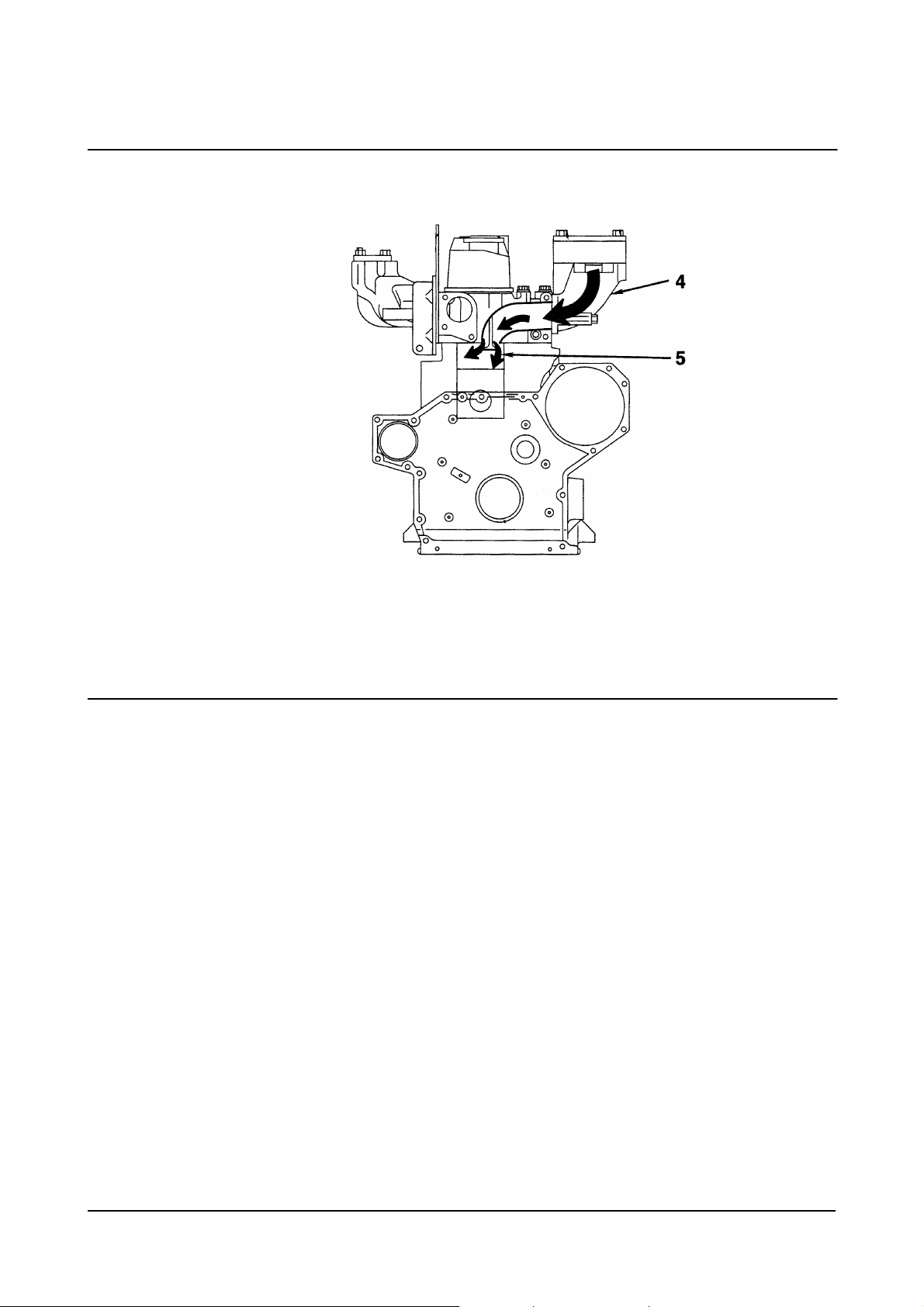
Temporarily position the fuel injection pump assembly
and measure the backlash of the gears.
Measure the backlash of all the gears with a dial
indicator.
Gear Housing Cover
NOTE: A noise damper is installed on some
engines. The noise damper must be
installed prior to installing the front oil seal.
Install the front oil seal using tool, Part No. 3824498.
Fill 40 to 60 percent of the space in the seal lip with
grease.
CAU
TIO
N
Do not apply excessive force to the seal lip
surface when aligning and installing the gear
housing cover. Damage to the engine will occur if
the seal is damaged.
NOTE: Apply gasket sealant, Part No. 3823494, to
the gear housing cover mounting surface.
Install the gear housing cover and 17 capscrews.
Tighten the capscrews.
Torque Value: 19 N•m [14 ft-lb]
Measure the distance in height between the cylinder
block and the gear housing cover.
Maximum Height Difference: 0.15 mm [0.0059 in]
00900247
Diesel Engine Complete Engine
71

00900180
00900179
00900178
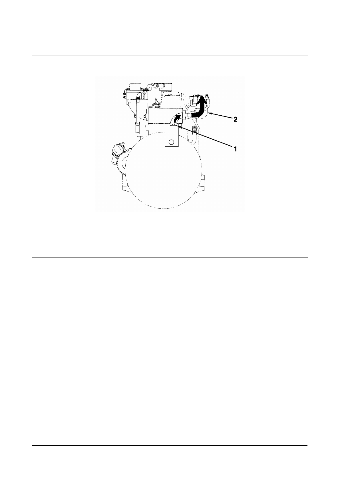
Crankshaft Pulley
Align the crankshaft pulley with the crankshaft key.
Install the crankshaft pulley, mounting plate, and
capscrew.
Tighten the capscrew.
Torque Value: 93 N•m [69 ft-lb]
Lubricating Oil Suction Tube
Install a new o-ring, oil suction tube, and two
capscrews.
Tighten the capscrews.
Torque Value: 19 N•m [14 ft-lb]
Lubricating Oil Pan
NOTE: Apply a 1-mm [0.039-in] bead of gasket
sealant, Part No. 3823494, to the mounting
surface of the lubricating oil pan.
Install a new gasket, lubricating oil pan, and 24
capscrews.
Tighten the capscrews.
Torque Value: 32 N•m [24 ft-lb]
If the oil drain plug was removed, install the drain plug.
Torque Value: 51 N•m [38 ft-lb]
PTO Shaft (if applicable)
Align the gear of the PTO shaft with the surface teeth
of the camshaft gear.
Install the o-ring, flange, and two capscrews.
Tighten the capscrews.
Torque Value: 19 N•m [14 ft-lb]
00900177
Diesel Engine Complete Engine
72

00900246
00900210
00900211
00900176
Fuel Injection Pump
CAU
TIO
N
Do not allow dirt or dust to enter the oil and fuel
inlet and outlet ports. Severe engine damage will
occur if contaminants are allowed to enter the
engine.
Install new o-ring, fuel injection pump, and two
mounting nuts on the adapter plate.
Tighten the nuts.
Torque Value: 31 N•m [23 ft-lb]
Install the fuel injection pump gear, washer, and nut
on the fuel injection pump.
Tighten the nut.
Torque Value: 70 N•m [52 ft-lb]
NOTE: Align the fuel injection pump gear match
mark “C” with the idler gear match mark “C”.
Install new o-ring, adapter plate, fuel injection pump
assembly, and mounting capscrews to the gear
housing.
Tighten the mounting capscrews.
Torque Value: 19 N•m [14 ft-lb]
Install the mounting capscrew on the fuel injection
pump support bracket.
Tighten the capscrew.
Torque Value: 19 N•m [14 ft-lb]
NOTE: The fuel supply tube has a 12-mm and 14-
mm banjo fitting. The 12-mm banjo fitting
connects to the fuel injection pump. The 14-
mm banjo fitting connects to the fuel filter
head, which is installed later in the
assembly process.
Install the fuel supply tube to the fuel injection pump.
Torque Value: 20 N•m [15 ft-lb]
Diesel Engine Complete Engine
73

00900174
00900173
00900172
Cylinder Head Assembly
NOTE: Coat the stems of the intake and exhaust
valves and the inside of the valve guides
with engine oil.
Install the valves.
Install the valve spring and spring seat on the valve
stem.
Install the valve cotter into the valve stem groove
while compressing the valve spring with spring pusher,
Part No. 3398179.
After releasing the valve spring, tap the top of the
valve stem with a plastic hammer to make certain the
cotter is completely fitted.
00900252
Diesel Engine Complete Engine
74

00900253
00900254
00900245
Remove all carbon and dirt from the contact
surfaces of the cylinder block and the cylinder
head. Remove all burrs and damage, and clean
out all the dirt from inside the cylinder block.
Failure to follow these steps will result in severe
engine damage.
Install a new cylinder head gasket with the TOP mark
facing up.
This component weighs 23 kg [50 lb] or more. To
avoid personal injury, use a hoist or get
assistance to lift this component.
NOTE: Coat the capscrew threads with antifriction
compound, Part No. 3824879.
Install the cylinder head using four head capscrews
as guides.
Install the capscrews. Tighten the capscrews in the
sequence shown.
Torque Value:
Cylinder Head
Capscrews Step 1 69 N•m [51 ft-lb]
2 108 N•m [80 ft-lb]
3 Rotate 90 degrees
NOTE: The cylinder head capscrews can be reused
five times. Make a punch mark on the
capscrew head each time the capscrew is
used. If there are already five marks on the
capscrew head, the capscrew must be
replaced.
Push Rods
NOTE: If there is no abnormality in the pushrods,
install them in the same position that they
were removed from during disassembly.
CAU
W
ARNIN
TIO
N
G
00900170
Diesel Engine Complete Engine
75

1. Rocker Shaft
2. Adjusting Screw Lock Nut
3. Pedestal Mounting Capscrews
4. Separating Spring
5. Rocker Shaft Indexing Screw
6. Pedestal Mounting Stud
Rocker Arm Assembly
00900169
00900251
7. Cup Plug
8. Snap Ring
9. Thrust Washer (only used on some engines)
10. Rocker Lever Pedestal
11. Rocker Lever
12. Adjusting Scre w.
Rocker Arm Assembly
NOTE: Check that the ball of the adjustment screw
is fitted properly into the socket of the
pushrod before tightening the capscrews. If
the valve spring tension pushes against the
rocker arm, loosen the locknut, and turn the
adjustment screw back to prevent strain on
the pushrod.
Install the rocker arm assembly and eight capscrews.
Tighten the capscrews.
Torque Value: 25 N•m [18 ft-lb]
Diesel Engine Complete Engine
76

03900077
03900075
fi9slwb
00900167
Adjusting Valve Clearance
Adjust the valve clearance. Refer to Section 14.
Rocker Lever Cover
Install the o-ring into the rocker lever cover.
Install the rocker lever cover, three capscrews, and
isolator assemblies.
Tighten the capscrews.
Torque Value: 9 N•m [7 ft-lb]
Injector
Coat the injectors with anti-sieze compound, Part No.
3824879, before installation.
CAU
TIO
N
Be careful not to damage the tip of the injector
when installing.
NOTE: When installing the injector, clean around
the injector, and do not allow dust or dirt to
enter the engine.
NOTE: If there is no abnormality in the injector,
install it in the same position during
assembly.
Install the injector, washer, and mounting capscrew.
Tighten the capscrew.
Torque Value: 44 N•m [33 ft-lb]
Diesel Engine Complete Engine
77

00900166
00900164
00900163
Spill Tube
Install the spill tube.
Intake Manifold
NOTE: Apply a 1-mm [0.039-in] bead of gasket
sealant, Part No. 3823494, to the mounting
surface of the intake manifold.
Install the air inlet connection, intake manifold, and
seven capscrews.
Tighten the capscrews.
Torque Value: 40 N•m [30 ft-lb]
Fuel Injection Tubing
NOTE: Before installing the fuel injection tubing,
blow compressed air through it to clean it.
Position the fuel injection tubing, and loosely install
the sleeve nuts on the fuel injection pump and the
cylinder head.
Tighten the clamp.
Tighten the banjo fittings
Torque Value: 20 N•m [15 ft-lb]
Exhaust Manifold
Install a new gasket, the exhaust manifold, and the
eight capscrews.
Tighten the capscrews.
Torque Value: 66 N•m [49 ft-lb]
00900162
Diesel Engine Complete Engine
78

18900025
00900161
00900160
Thermostat
Install seal, thermostat, thermostat housing, and two
mounting capscrews.
Tighten the capscrews.
Torque Value: 19 N•m [14 ft-lb]
Water Pump
Install the o-ring, gasket, water pump, and mounting
capscrews.
Tighten the capscrews.
Torque Value: 19 N•m [14 ft-lb]
Dipstick
NOTE: Apply Loctite™ sealant, Part No. 3375068,
or equivalent, to the outside of the dipstick
tube.
CAU
TIO
N
Excessive sealant can run back into the engine
and cause damage to other components.
Install the dipstick guide.
Install the dipstick.
Diesel Engine Complete Engine
79

00900155
cs9pxea
cs9orwa
Lubricating Oil Filter
Install the lubricating oil filter.
NOTE: Some engines will have an oil filter cooler
mounted between the oil filter and the
engine block.
Block Water Heater
Clean the core plug hole thoroughly. Make sure there
are not burrs or sharp edges that might cut the o-ring.
Lubricate the new heater o-ring with clean engine oil.
The locking channel (T-Bar) should be threaded out
to the end of the bolt. If so equipped, do not remove
the retaining wire used to position the channel (T-Bar).
cs900wg
Diesel Engine Complete Engine
80

cs900wh
cs900wi
cs900hb
Hook the element and one leg of the channel (T-Bar)
into the hole as illustrated.
Hook the other leg of the channel in the hole and
push the heater into the hole as far as possible by
hand.
CAU
TIO
N
Do not pull the heater into location with the
locking bolt as the channel (T-Bar) can bend or
cause the threads to strip.
If necessary, use a plastic hammer to tap the heater
in until the shoulder contacts the block.
Tighten the locking bolt.
Torque Value: 2.0 N•m [18 in-lb]
Do not over-tighten the locking bolt.
cs9bona
Diesel Engine Complete Engine
81

cs900hc
00900159
00900255
Insert the power cord into the socket being careful to
align the pins with the sockets of the power cord.
Tighten the retaining nut by hand.
Do not apply power until the cooling system is filled,
and run the engine long enough for the thermostats to
open and ensure all the air has escaped.
Alternator
Install the alternator and capscrew.
Install the spacer, mounting capscrew, and
adjustment plate.
Loosely install the washer and adjustment capscrew.
Fan Pulley
Install the fan pulley.
Position the fan belt (2) into the fan pulley groove,
and loosely tighten the adjustment capscrew (1).
00900158
Diesel Engine Complete Engine
82

00900257
00900157
00900209
Be careful not to injure your fingers or damage
the alternator when adjusting the belt tension.
Insert a bar or pipe between the alternator and the
cylinder block. Raise the alternator to adjust the fan
tension.
NOTE: The belt must deflect 7 mm to 10 mm [0.28
in to 0.39 in] when pushed with finger-
pressure of 6 kg [13 lb] at a point midway
between the fan pulley and the crankshaft
pulley.
Tighten the adjustment capscrew (1).
Torque Value:
Mounting
Capscrew
Adjustment
Capscrew
Fan
Install the spacer, fan, four capscrews.
Tighten the capscrews.
Torque Value: 31 N•m [23 ft-lb]
Remove the covers on all the engine openings that
were installed to prevent dirt and debris from entering
the engine.
W
ARNIN
G
31 N•m [23 ft-lb]
31 N•m [23 ft-lb]
Diesel Engine Complete Engine
83

00900208
00900207
00900156
This component weighs 23 kg [50 lb] or more. To
avoid personal injury, use a hoist or get
assistance to lift this component. The engine
lifting equipment must be designed to lift the
engine without causing personal injury.
Engine Weight (approx.) 330 kg [660 lb]
Remove the engine from the stand.
Remove the bracket, Part No. 3163625, from the
engine.
Install the starting motor.
NOTE: The o-ring is used only on wet flywheel
housings.
Install all the chassis components that were removed
during removal of the engine from the equipment.
W
ARNIN
G
Diesel Engine Complete Engine
84

tr400wa
oi400ha
sb8coma
07900034
Connect the drive units to the flywheel housing and
flywheel.
`
Connect the intake and exhaust system pipes.
Connect the starter cable, engine ground straps, cab
or chassis to engine hoses, tubing, electrical wires,
and hydraulic lines.
W
ARNIN
Always connect the negative (-) cable last.
Connect the battery cables.
W
ARNIN
Some state and federal agencies in the United
States of America have determined that used oil
is carcinogenic and can cause reproductive
toxicity. Avoid inhalation of vapors, ingestion, and
prolonged contact with used engine oil. Always
use the proper procedures to dispose of the oil.
Fill the engine with lubricating oil.
Engine Oil 6.5 liters [1.7 u.s.gal]
G
G
Diesel Engine Complete Engine
85

ra800wn
fp8hola
Coolant is toxic. Keep away from children and
animals. Save for reuse or dispose of in
accordance with local regulations.
Fill the engine with engine coolant.
NOTE: Remove all tags that were put on all hoses,
lines, linkage, and electrical connections as
they were removed to identify location
during the removal process.
W
ARNIN
G
Diesel Engine Complete Engine
86

Rocker Levers
Adjusting Valve Clearance
03900075
0390076
0390077
Remove the cylinder head cover.
Rotate the crankshaft in the normal direction.
While watching the movement of the intake valve of
No. 4 cylinder, bring the No.1 cylinder into
compression top dead center position
Align the TOP engraved mark on the crankshaft
pulley (1) with pointer (2).
NOTE:
• The engraved mark on the crankshaft pulley will
read “1.4 TOP.”
• The No. 4 intake valve will start to open when the
No. 1 cylinder comes near compression top
dead center.
Loosen the lock nut (3) on the adjustment screw (4).
Insert the feeler gauge (5) between the valve stem (6)
and the rocker arm (7).
Adjust the clearance with the adjustment screw until
slight drag is felt on the feeler gauge.
Valve Clearance (Engine Hot or Cold)
Intake Valve Exhaust Valve
0.35 mm 0.50 mm
0.014 in 0.020 in
Diesel Engine Engine Testing
87

0390078
0390079
0390078
NOTE: Adjust intake and exhaust clearances in the
following firing order by rotating the
crankshaft 180 degrees in the normal
direction: 1-2-4-3.
Adjust the valve clearances for intake valves No. 1
and No. 3.
Adjust the valve clearances for exhaust valves No. 1
and No. 2.
Rotate the crankshaft in the normal direction one
revolution.
Adjust the valve clearances for intake valves No. 2
and No. 4.
Adjust the valve clearances for exhaust valves No. 3
and No. 4.
Tighten the locknut to secure the adjustment screw.
Locknut Torque Value
N•m ft-lb
39.2 MIN 28.9
49 MAX 36.1
0390080
Diesel Engine Engine Testing
88

Complete Engine
Measuring Compression Pressure
W
ARNIN
Exhaust manifold and muffler are hot. Do not
touch the exhaust manifold or muffler or personal
injury will occur.
G
0390077
0390166
W
To avoid personal injury, keep hands, long hair,
jewelry, and loose fitting or torn clothing away
from fans and other moving parts.
Adjust the overhead. Refer to Adjusting Valve
Clearance procedure.
Remove the spill tube.
Disconnect the fuel injection tubing.
NOTE: Disconnect the fuel shut-off solenoid.
ARNIN
G
0390163
Diesel Engine Engine Testing
89

0390167
fi9slwb
14900059
14000060
Do not allow dirt or foreign matter to get into the
cylinder. Foreign objects in the cylinder can
cause severe engine damage.
Remove the nozzle holder assembly for each cylinder.
Remove the injector.
Lubricate the sealing lips of the sleeve with anti-seize
compound. Assemble the injector, sealing sleeve, a
new copper sealing washer, and the hold-down clamp.
Use only one washer.
NOTE: A light coat of clean 15W-40 engine oil
between the washer and injector can help
hold the washer in place during installation.
Install the adapter to the nozzle holder mounting
section of the cylinder to be measured. Tighten the
adapter.
N•m ft-lb
39 MIN 29
49 MAX 36
Connect the compression gauge to the adapter.
NOTE: Most compression leakage can be
prevented by applying a small amount of oil
to the mounting section of the adapter.
CAU
TIO
N
Adapter Capscrews
Diesel Engine Engine Testing
90

14000062
fa9blsh
14000068
00900257
Crank the engine with the starting motor. Read the
gauge when the pointer is stabilized.
Engine Compression
kPa psi
1965 MIN 285
2944 NOM 427
Testing and Adjusting the Fan Belt
Tansion
Testing the Fan Belt Tension
Check the amount the fan belt deflects when pushed
with a force of 6 kg [13.2 lb] at a point midway
between the fan pulley and the alternator pulley.
Fan Belt Deflection
mm in
7.0 MIN 0.28
10.0 MAX 0.39
Adjusting the Fan Belt Tension
Loosen the mounting capscrew of the alternator (1)
and belt tension adjustment capscrew (2).
Using a bar, raise the alternator, and adjust the fan
belt tension.
Tighten the adjustment capscrew and the mounting
capscrew.
Torque Value:
Adjustment
Capscrew
Mounting
Capscrew
31 N•m [23 ft-lb]
66 N•m [49 ft-lb]
Diesel Engine Engine Testing
91

Fuel System
Checking and Adjusting Fuel
Injection Timing
14900070
14900071
There are two methods for checking and adjusting the
fuel injection timing of an injection pump.
• The “MATCH MARK ALIGNMENT” method,
which is used when the injection pump is
installed on the original engine and the pump is
not being repaired.
• The “MEASURING DEVICE” method, which is
used when a repaired or replaced injection
pump is installed on the engine.
Checking and Adjusting with the Match Mark
Alignment Method
NOTE: Set the No. 1 cylinder at compression top
dead center (TDC) by aligning the pointer
on the gear cover with the TDC line on the
crankshaft pulley. Confirm that the mark “C”
can be seen on the idler gear. If the mark
“C” can not be seen, rotate the crankshaft
one complete revolution and confirm that
“C” can be seen.
NOTE: Align the match mark “C” on the injection
pump gear with the match mark “C” on the
idler gear during installation for correct
alignment. Align the stamped line “a” on the
injection pump with the stamped line “b” on
the timing gear case during installation for
correct alignment.
Install the injection pump.
Diesel Engine Engine Testing
92

14900072
14900073
14900074
If the stamp lines are out of alignment, loosen nut (7).
Align the stamp lines by rotating the coupling.
Tighten the nut.
Torque Value: 31 N•m [23 ft-lb]
Checking and Adjusting with the Measuring
Device Method
NOTE: Set the No. 1 cylinder at compression top
dead center (TDC) by aligning the pointer
on the gear cover with the TDC line on the
crankshaft pulley.
Remove the distributor head bolt and copper washer
from the injection pump.
Discard the copper washer.
Install the dial gauge, Part No. 3377259, into the
distributor head.
NOTE: Check that the stylus end of the dial gauge
contacts the plunger head.
14900075
Diesel Engine Engine Testing
93

14900076
14900077
14900070
Rotate the crankshaft opposite normal engine rotation
(counterclockwise) slightly, until the dial gauge does
not move any longer.
Set the dial gauge pointer to 0.
Rotate the crankshaft in the normal direction until the
dial gauge reads 1.0 ± 0.3 mm [0.04 ± 0.01 in].
Look at the pointer on the crankshaft. It should point
to the timing mark in degrees as stamped on the
dataplate. The timing marks on the crank pulley range
from 6 to 14 degrees in two degree increments.
NOTE: Check the values on the data plate. Values
may change as new ratings are developed.
NOTE: The gauge reading ±0.03 mm [0.001 in] is
equivalent to ±0.5 degrees fuel injection
timing.
NOTE: The crankshaft must be rotated in the
normal direction (clockwise looking from
the front of the engine) without stopping.
If the dial readings are not within the standard value,
loosen nut. Adjust the fuel injection timing to within
standard value by rotating the injection pump body.
Tighten the nut.
Torque Value: 31 N•m [23 ft-lb]
14900078
Diesel Engine Engine Testing
94

14900074
14900080
14900082
Remove the dial gauge.
Install the distributor head bolt and new copper
washer into the injection pump.
Tighten the bolt.
Torque Value: 17 N•m [13 ft-lb]
Stamp a match mark on the injection pump and the
timing gear case.
Adjusting the Idle
Move the governor control lever to the desired idling
speed by using the idling adjustment screw.
Injector
Testing
W
ARNIN
Keep your body clear of test spray. Fluid can be
injected into the bloodstream causing blood
poisoning and possible death.
NOTE: All nozzles must be tested for opening
pressure, chatter and spray pattern.
G
fi900sa
Diesel Engine Engine Testing
95

fi900de
fi900oa
fi900df
Check the opening pressure.
a. Open valve.
b. Operate lever at one stroke per second.
c. Read pressure indicated when spray begins.
If the opening pressure is out of specification,
disassemble the injector and change the shims in
order to change the opening pressure.
NOTE: .01 mm [0.0039 in] shim thickness equals
41 bar [595 psi].
Leakage Test
a. Open the valve.
b. Operate the lever to hold pressure 20 bar [290
psi] below opening pressure.
c. No drops should fall from the tip within 10
seconds.
Chatter Test
The chatter test indicates the ability of the needle
valve to move freely and correctly atomize the fuel.
An audible sound should be heard as the valve
rapidly opens and closes. A well optimized spray
pattern should be seen.
Used nozzles should not be evaluated for chatter at
lower speeds. A used nozzle can generally be used if
it passes the leakage test.
fi900dd
Diesel Engine Engine Testing
96

filsema
fi900fb
fi900fc
Disassembly
Remove the copper sealing washer and discard.
Clamp the nozzle holder in a soft jawed vise and
remove the nozzle nut.
Remove the nozzle needle valve and intermediate
plate.
NOTE: To avoid damage, place the injector nozzle
and needle valve in a suitable bath of clean
test oil.
Remove the nozzle holder from the vise; then remove
the pressure spindle, pressure spring, and shims.
fi900fd
Diesel Engine Engine Testing
97

fi900ab
fi900ha
fi900ce
fi900ad
Assembly
NOTE: Make sure all mating surfaces and pressure
faces are clean and lubricated with fuel oil
before assembly.
W
ARNIN
Install the same thickness of shims that were
removed in disassembly. Use the pressure spring
to make sure the shims are installed flat.
Install the shims.
Clamp the nozzle holder in a soft jawed vise and
install the spindle.
Install the intermediate plate.
G
Diesel Engine Engine Testing
98
 Loading...