

Daewoo D20S-2, G20S-2, GC20S-2, D20-2, G25S-2 Specifications Systems Operation Testing & Adjusting Disassembly & Assembly
...
Aug. 1996
Specifications
Systems Operation
T esting & Adjusting
Disassembly & Assembly
New Hydraulic Systems
D20/25-2
D20/25/30S-2
G20/25/30S-2
G20/25/30S-2
SB2097E00

Important Safety Information
Most accidents involving product operation, maintenance and repair are caused by failure to observe
basic safety rules or precautions. An accident can often be avoided by recognizing potentially
hazardous situations before an accident occurs. A person must be alert to potential hazards. This
person should also have the necessary training, skills and tools to perform these functions properly.
Improper operation, Iubrication, maintenance or repair of this product can be dangerous and
could result in injury or death.
Do not operate or perform any Iubrication, maintenance or repair on this product, until you
have read and understood the operation, Iubrication, maintenance and repair information.
Safety precautions and warnings are provided in this manual and on the product. If these hazard
warnings are not heeded, bodily injury or death could occur to you or other persons.
The hazards are identified by the "Safety Alert Symbol" and followed by a "Signal Word" such as
"WARNING" as shown below.
The meaning of this safety alert symbol is as follows :
Attention! Become Alert! Your Safety is Involved.
The Message that appears under the warning, explaining the hazard, can be either written or
pictorially presented.
Operations that may cause product damage are identified by NOTICE labels on the product and in
this publication.
DAEWOO cannot anticipate every possible circumstance that might involve a potential hazard. The
warnings in this publication and on the product are therefore not all inclusive. If a tool, procedure,
work method or operating technique not specifically recommended by DAEWOO is used, you must
satisfy yourself that it is safe for you and others. You should also ensure that the product will not be
damaged or made unsafe by the operation, Iubrication, maintenance or repair procedures you
choose.
The information, specifications, and illustrations in this publication are on the basis of information
available at the time it was written. The specifications, torques, pressures, measurements,
adjustments, illustrations, and other items can change at any time. These changes can affect the
service given to the product.
Obtain the complete and most current information before starting any job. DAEWOO dealers have
the most current information available.
1 of 29
WARNING

Index
Specifications
Hydraulic Control Valve .......................................... 5
Systems Operation
Hydraulic Control Valve ........................................ 17
Assembly And Construction .......................... 17
Check Valve .................................................. 21
Flow Control Valve And Relief Valve ............ 20
Valve Operation ............................................ 18
Hydraulic System (D20/25/30S-2,
G20/25/30S-2, GC20/25/30S-2 Model)................. 6
Hydraulic System (D20/25-2 Model Only) ............ 11
Anti-Stall And Remote Relief Valve .............. 14
Testing And Adjusting
Hydraulic System .................................................. 23
Flow Control Valve Adjustment ..................... 24
Relief Valve Pressure Check ........................ 23
Troubleshooting .................................................... 22
Disassembly And Assembly
Assembly .............................................................. 28
Cleaning, Inspection And Repair .......................... 26
General ................................................................. 25
Unit Disassembly .................................................. 25
3 of 29New Hydraulic Systems Index
Specifications
Hydraulic Control valve
(1) Torque for bolts that hold control valve sections
together
................
40.5
±2 N
•
m (360 ±18 lb
•
in)
(2) Adjust TILT and sideshift relief valve pressure as
shown above. See Relief Valve Pressure Check
in Testing And Adjusting.
(3) Torque for nipple assembly
........
36.5
±0.5 N
•
m
(320
±4 lb
•
in)
See Folw Control Valve Adjstment in Testing And
Adjusting.
(4) Torque for screws
............................
12 ±1.5 N
•
m
(105
±13 lb
•
in)
5 of 29New Hydraulic Systems Specifications
CONTROL VALVE
TILT, Auxiliary
Relief Valve
Pressure
±350 kPa
(
±50 psi)
15,500 (2250)
15,500 (2250)
15,500 (2250)
Main Relief
Valve
Pressure
± 500 kPa
(
±75 psi)
18,100 (2625)
19,500 (2825)
21,550 (3125)
Mast
Std
FFL
FFTL
Std
FFL
FFTL
Std
FFL
FFTL
Model
D(G)20(S)
GC20(S)
D(G)25(S)
GC25(S)
D(G)30S
GC30S
2
1
3
IDCS001B
Systems Operation
Hydraulic System
(D20/25/30S-2, G20/25/30S-2, GC20/25/30S-2 Model)
6 of 29New Hydraulic Systems Systems Operation
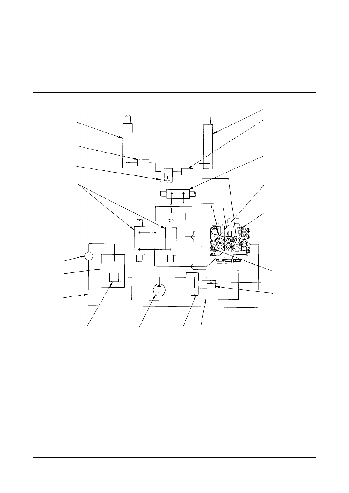
Basic Hydrauic Schematic With Standard Lift
(1) Lift cylinders. (2) Excess flow protectors. (3) Sideshift cylinder(s)(if equipped). (4) Lowering flow control valve. (5) Hydraulic
control valve. (6) Tilt cylinders (7) Relief valve(lift). (8) Relief valve(tilt and sideshift). (9) Hydraulic oil filter. (10) Hydraulic oil
tank. (11) Priority valve. (12) Oil line(trucks with power brakes only). (13) Oil line. (14) Hydraulic strainer. (15) Hydraulic pump.
(16) Oil line to steering gear. (17) Oil line.
12
11
8
5
7
3
2
1
1
2
4
6
9
10
13
14 15
16 17
IDCS002B

The hydraulic system has hydraulic oil tank (10)
which holds the oil for gear type hydraulic pump (15).
Hydraulic pump (15) sends pressure oil to the power
brakes (if equipped), hydraulic and steering systems.
Pump oil flows from pump (15) to priority valve (11)
where the oil folw divides to the power brakes brake
valve (if equipped)(not shown) through line (12) and
to the steering gear through line (16).
The control valve levers move the valve spools in
control valve (5) to let the pump oil in the control
valve go to lift cylinders (1) and/or (19), tilt cylinders
(6) or sideshift cylinder(s) (3).
The return hydraulic oil from the cylinders flows
through hydraulic control valve (4), line (13), into filter
(9) and hydraulic tank (10). Relief valve (7) in the
control valve body will make the flow control valve
release extra pressure to the hydraulic tank when the
pressure in the lift or tilt circuits goes higher than
relief valve pressure shown in the Control Valve
section of Specifications. Relief valve (8) does the
same thing for the sideshift circuit when it goes
higher than the auxiliary relief valve pressure shown
in the Control Valve section of Specifications.
7 of 29New Hydraulic Systems Systems Operation
The maximum speed at which the lift cylinder(s) are
lowered is controlled by lowering flow control valve (4).
Excess flow protectors (2) and (18) will act as flow
control valve if an oil line between them and flow
control valve (4) is broken when the mast is raised or
lowered. This prevents a sudden fall of the mast or
carriage if an oil line is broken.
The tilt forward, tilt back and sideshift speeds are
controlled by flow control valves in hydraulic control
valve (5). There is an anti-cavitation valve inside the tilt
spool to prevent cavitation (development of air pockets)
in tilt cylinders (6).
REFERENCE : For the Hydraulic Systems Schematics.
8 of 29New Hydraulic Systems Systems Operation
Basic Hydraulic Schematic With Standard Lift
(1) Lift cylinders. (2) Excess flow protectors. (3) Sideshift cylinder(s)(if equipped). (4) Lowering folw control valve. (5) Hydraulic
control valve. (6) Tilt cylinders. (7) Relief valve(lift). (8) Relief valve(tilt and sideshift). (9)Hydraulic oil filter. (10) Hydraulic oil
tank. (11) Priority valve. (12) Oil line(trucks with power brakes only). (13) Oil line. (14) Hydraulic strainer. (15) Hydraulic pump.
(16) Oil line to steering gear. (17) Oil line. (18) Excess folw protector. (19) Lift cylinder(primary).
18
19
1
2
4
6
9
10
13
14 15
16
17
12
11
8
5
7
3
2
1
IDCS003B

Hydraulic System (D20/25-2 Model Only)
11 of 29New Hydraulic Systems Systems Operation
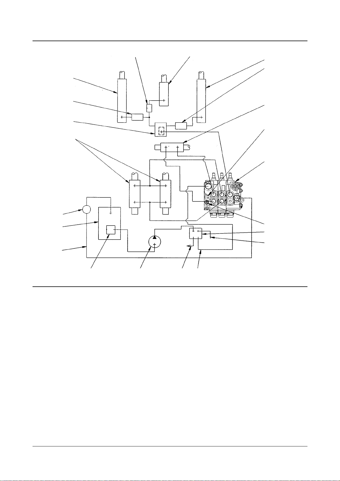
Basic Hydraulic Schematic With Standard Lift
(1) Lift cylinders. (2) Excess flow protectors. (3) Sideshift cylinder(s)(if equipped). (4) Lowering folw control valve. (5) Hydraulic
control valve. (6) Tilt cylinders. (7) Relief valve(lift). (8) Relief valve(tilt and sideshift). (9) Hydraulic oil filter. (10) Hydraulic oil
tank. (11) Priority valve. (12) Oil line(trucks with power brakes only). (13) Oil line. (14) Hydraulic strainer. (15) Hydraulic pump.
(16) Oil line to steering gear. (17) Oil line. (18) Remote relief valve. (19) Oil line(trucks with anti-stall valve only). (20) Anti-stall
valve(if equipped).
1
2
4
6
9
10
13
14
15
16 17 18
19
20
12
11
8
5
7
3
2
1
IDCS004B

The hydraulic system has hydraulic oil tank (10) which
holds the oil for gear type hydraulic pump (15).
Hydraulic pump (15) sends pressure oil the power
brakes (if equipped), hydraulic and steering systems.
Pump oil flows from pump (15) to priority valve (11)
where the oil folw divides to the power brakes brake
valve (if equipped)(not shown) through line (12) and to
the steering gear through line (16). Oil also flows
through anti-stall valve (20), to hydraulic control valve
(5) and back to hydraulic tank (10).
When the lift truck is at idle speed the hydraulic pump
delivers a low oil flow. If the lift, tilt or auxiliaries are
used the pressure in line (17) will increase and
remote relief valve (18) will dump oil to hydraulic tank
(10). As engine speed is increased, oil flow
increases, anti-stall valve (20) now closes the
passage to remote relief valve (18). With remote
relief valve (18) blocked, normal hydraulic relief
pressures are available.
The control valve levers move the valve spools in
control valve (5) to let the pump oil in the control
valve go to lift cylinders (1) and/or (22), tilt cylinders
(6) or sideshift cylinder(s) (3).
The return hydraulic oil from the cylinders flows
through hydraulic control valve (4), line (13), into filter
(9) and hydraulic tank (10). Relief valve (7) in the
control valve body will make the flow control valve
release extra pressure to the hydraulic tank when the
pressure in the lift or tilt circuits goes higher than
relief valve pressure shown in the Control Valve
section of Specifications. Relief valve (8) does the
same thing for the sideshift circuit when it goes
higher than the auxiliary relief valve pressure shown
in the Control Valve section of Specifications.
12 of 29New Hydraulic Systems Systems Operation

The maximum speed at which the lift cylinder(s) are
lowered is controlled by lowering flow control valve (4).
Excess flow protectors (2) and (21) will act as flow
control valve if an oil line between them and flow
control valve (4) is broken when the mast is raised or
lowered. This prevents a sudden fall of the mast or
carriage if an oil line is broken.
The tilt forward, tilt back and sideshift speeds are
controlled by flow control valves in hydraulic control
valve (5). There is an anti-cavitation valve inside the
tilt spool to prevent cavitation (development of air
pockets) in tilt cylinders (6).
REFERENCE : For the Hydraulic Systems Schematics.
13 of 29New Hydraulic Systems Systems Operation
Basic Hydraulic Schematic With Standard Lift
(1) Lift cylinders. (2) Excess flow protectors. (3) Sideshift cylinder(s)(if equipped). (4) Lowering folw control valve. (5) Hydraulic
control valve. (6) Tilt cylinders. (7) Relief valve(lift). (8) Relief valve(tilt and sideshift). (9) Hydraulic oil filter. (10) Hydraulic oil
tank. (11) Priority valve. (12) Oil line(trucks with power brakes only). (13) Oil line. (14) Hydraulic strainer. (15) Hydraulic pump.
(16) Oil line to steering gear. (17) Oil line. (18) Remote relief valve. (19) Oil line(trucks with anti-stall valve only). (20) Anti-stall
valve. (21) Excess flow protector. (22) Lift cylinder(primary).
6
4
2
1
9
10
13
14
15
16
17 18
19
20
12
11
5
7
3
2
1
2221
8
IDCS005B

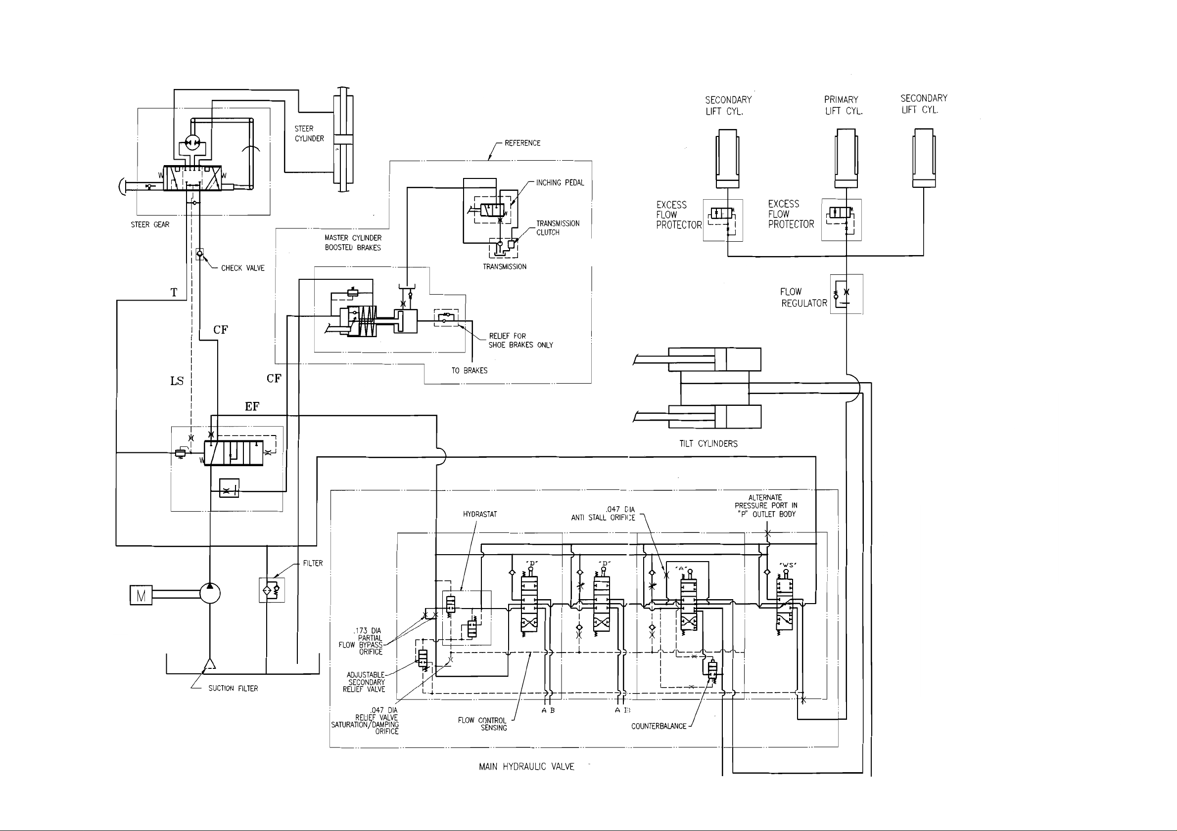
Anti-Stall And Remote Relief Valve
The anti-stall valve in combination with the remote
relief valve prevent hydraulic overloads at engine
idle, which could cause excessive vibration and
engine stalling. At engine idle, the anti-stall valve
opens ports to the hydraulic control valve and the
remote relief valve. If the hydraulic control valve is
used, the pressure in the oil line from the priority
valve to the anti-stall valve will increase. This
pressure increase will be limited by the remote relief
valve to 8250 kPa (1200 psi) (6R7072 Relief Valve).
This relatively low system pressure allows for a
smoother engine idle because the engine is not
overloaded by the hydraulic pump with an engine
speed of 700 rpm minimum.
As engine speed increases the hydraulic system oil
flow increases. The anti-stall valve senses this flow
increase and closes the output port to the remote
relief valve. Flow is now directed to the main control
valve only and full system pressure can be achieved.
14 of 29New Hydraulic Systems Systems Operation


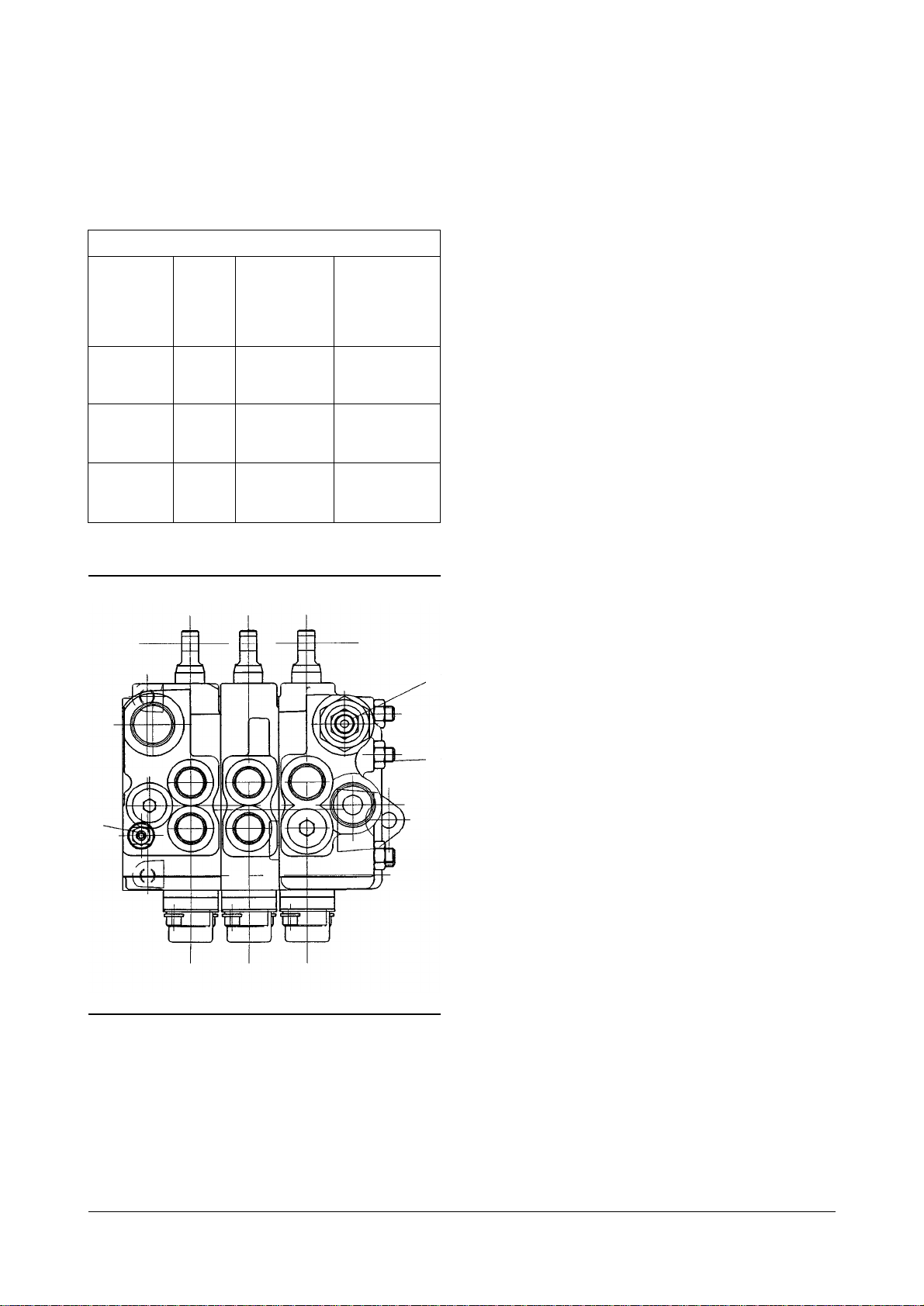
Assembly And Construction
Above figure is a cross-section view showing
construction and assembly of a three-section valve.
The inlet section also contain a relief valve
assembly.
Passages between the bodies connect each section
to the common inlet and tank ports.
Seal rings between the sections seal the connecting
passages, Sections are held together by studs and
nuts.
17 of 29New Hydraulic Systems Systems Operation
(1) Relief Valve. (2) Inlet Body. (3) Center Spring. (4) Switch Bracket.
(5) Cam. (6) Center Body. (7) Spool. (8) Tie Stud.
(9) Outlet Body. (10) Check Valve. (11) Seal Rings.
Hydraulic Control Valve
IDCS006B

18 of 29New Hydraulic Systems Systems Operation
Valve Operation
Figure IDCS007B is a schematic illustration of a
three section valve, showing the inlet and outlet ports
and the by-pass, pressure and tank passages.
The pressure passage is used to carry fluid to the
cylinder ports when the spools are shifted. The bypass passage permits flow directly to the outlet when
the spools are not being operated. The tank passage
also carries fluid to the outlet; either return flow from
the cylinder ports or fluid diverted past the flow
control and relief valve,
The spools are shown in the centered or neutral
position, Under these conditions, fluid in the pressure
passage is blocked from the cylinder ports by the
spool lands. Flow through the valve is through the
by-pass and tank passages to the outlet.
(1) Control Valve Sensing Orifice.
(2) Flow Control And Relief Valve.
(3) Tank Passage.
(4) By-pass Flow Control Orifice.
(5) Cylinder Ports.
(6) Pressure Passage. (7) By-pass Passage.
IDCS007B
Lift Spool
IN Pressure to “B
”
“
A”to tank
By-pass blocked
CENTER
“A”
and “B”blocked
By-pass open
OUT
“B”
to tank
“A”
blocked
By-pass open
Lift spool - used for control of single acting cylinder
applications. It directs flow to only one end of a
cylinder, as in the lift mechanism of a lift truck.
Return flow is from the same end of the cylinder and
relies on gravity or mechanical means to retract.
IDCS008B
IDCS009B

19 of 29New Hydraulic Systems Systems Operation
Tilt Spool
IN
“A”
to tank
“B”
blocked
By-pass open
CENTER
“A”
and “B”blocked
By-pass open
OUT Pressure to
“A”
“
B”blocked
By-pass blocked
Tilt spool - a counterbalance spool normally used to
control the tilt function of a lift truck.
The counterbalance feature prevents the forks from
tilting forward faster than the pump can supply oil,
preventing tilt.
IDCS012B
Auxiliary Spool
IN Pressure to “B
”
“
A”to tank
By-pass blocked
CENTER
“A”
and “B”blocked
By-pass open
OUT Pressure to
“A”
“
B”to tank
By-pass blocked
Auxiliary spool - directs flow to either end of a double
acting cylinder. Flow from the end that is not under
pressure is returned to tank via internal coring of the
valve section.
IDCS010B
IDCS011B
IDCS013B

Flow Control And Relief Valve
Earlier design valves were equipped with simple relief
valves in the inlet sections.
The partial flow by-pass system in the LT valve
makes use of a compound type flow control and relief
valve arrangement.
Sensing the pressure drop across an orifice at the
entrance to the by-pass, the valve acting as a control
to limit flow through the by-pass to approximately
seven gallons per minute. The balance of the pump
delivery is diverted through the reservoir passage.
This arrangement greatly reduces pressure drop
through the valve in the neutral position.
When a spool is shifted to operate a portion of a
machine, the flow control is inoperative and full pump
volume is available to the system. The control valve
then functions as an overload relief valve. System
pressure is limited to a prescribed maximum by the
action of this valve. Inlet body type F is not equipped
with a relief valve. Full pump volume is available to
the system at all times.
Use of the optional secondary relief valve allows the
use of lower pressure for tilt and accessory function
while higher pressure is provided for the lift function.
NOTE : The secondary relief valve must be set at a
lower relief setting than the system relief.
Flow Control
(1) Control Valve Sensing Orifice.
(2) Flow Control And Relief Valve.
(3) Tank Passage.
(4) By-pass Flow Control Orifice.
(5) Cylinder Ports. (6) Pressure Passage.
(7) By-pass Passage.
Figure IDCS007B shows the valve operation in
neutral with flow in excess of seven USgpm. Flow
across the by-pass orifice result in a pressure drop.
Decreased pressure is sensed at the spring end of
the valve sub-assembly through a sensing orifice.
The slightly higher pressure at the other end of the
valve permits it to shift down, diverting excess flow to
the reservoir passage. With flow at less than seven
USgpm there would be negligible pressure drop
across the by-pass orifice. Then the control valve
would be held closed by the large spring and all flow
would be through the by-pass passage.
Optional flow control valves are available for all
operating sections. These valves can be set from
1 - 15 US gpm.
20 of 29New Hydraulic Systems Systems Operation
IDCS007B

Relief Valve
(1) Spring. (2) Spool. (3) Poppet.
(4) By-pass Flow Control Orifice.
(5) Flow Control And Relief Valve.
(6) Spring. (7) Sensing Orifice.
(8) Control Valve Sensing Orifice.
Operation of the relief valve feature is shown in
above figure. When an operating spool is shifted,
fluid is ported into the system and the by-pass is
blocked.
Above figure A shows operation at less than the relief
valve setting. There is no flow over the by-pass
orifice, so full system pressure is sensed at the spring
end of the control valve, as well as the opposite end.
The valve is thus hydraulically balanced and the large
spring holds the relief spool closed.
Maximum pressure is determined by the setting of
the small spring inside the control valve assembly.
When system pressure is sufficient to overcome this
heavy spring, the poppet is forced off its seat (see
above figure B).
Fluid immediately flows past the poppet to the tank
passage. This flow creates a pressure drop across
the sensing orifice and the control valve is no longer
hydraulically balanced.
When pressure drop across the sensing orifice is
great enough to overcome the force of the large
spring, the valve spool shifts, permitting flow to the
tank passage.
Relief valve sub-assemblies in the inlet section are
pre-set and tested by Vickers for given pressure
settings. Selection of the relief valves setting is based
on the work requirements of the system.
If a different relief valve setting is required, the valve
sub-assembly should be replaced,
Check Valve
(1) Spring. (2) Spool. (3) Poppet.
(4) By-pass Flow Control Orifice.
(5) Flow Control And Relief Valve.
(6) Spring. (7) Sensing Orifice.
(8) Control Valve Sensing Orifice.
Timing of the spools is such that one cylinder port
opens to pressure and the other port opens to
reservoir before the by- pass passage is
completelyblocked.
To prevent return flow from passing into the pressure
passage and escaping through the partially closed
by-pass, check valves are provided in each operating
section except sections with
“B”
spool.
The check valves prevent the load from dropping.
21 of 29New Hydraulic Systems Systems Operation
IDCS014B
Model
D20-2, D20S-2,
G20S-2, GC20S-2
D25-2, D25S-2
G25S-2, GC25S-2
D30S-2, G30S-2
GC30S-2
Part
Number
D144363
D144364
D144365
Setting
Pressure
2625 psi
(18,100 kPa)
2825 psi
(19,478kPa
3125 psi
(21,546 kPa)
IDCS014B

Testing And Adjusting
Troubleshooting
Below table lists the difficulties which may be
experienced with the unit and the hydraulic system. It
indicates the cause and remedy for each of the
trouble listed. It should always be remembered that
pressure and delivery are factors which are usually
dependent upon each other. Adequate pressure
gauge equippment and a thorough understanding of
the operation of the complete hydraulic system are
essential to diagnose improper conditions.
22 of 29New Hydraulic Systems Testing and Adjusting
Trouble :
Oil leaks at either end of spools.
Probable Cause
Defective O-rings in valve
body
Remedy
Replace O-rings
Trouble :
Spring-centered spools do not return to neutral.
Probable Cause
Broken springs
Bent spool
Foreign particles
Misalignment of operating
linkage
Valve bank improperly
torqued
Probable Cause
Worn detent barrel
Weak or broken detent
spring
Remedy
Replace springs
Replace with new section of
same size and type
Clean system and valve
Check linkage for binding
condition
Retorque nuts to specified
ratings
Remedy
Replace detent barrel
Replace detent spring
Trouble :
Detent type spools will not stay in detent position
Trouble :
No motion, slow or jerky action of hydraulic system
Probable Cause
Relief valve not properly set, or
stuck in base and/or worn
Dirt or foreign particles lodged
between relief valve control poppet
and seat
Valve body cracked inside
Spool not moved to full stroke
Remedy
Repair, clean and readjust
Disassemble, clean and
reassemble
Replace valve section
Check travel
Trouble :
No relief valve action (high pressure)
Probable Cause
Small particle of dirt plugging
orifice in relief valve subassembly
Relief valve sub-assembly
installed backward
Remedy
Remove relief valve and
check hole. If blocked, clear
hole
Install properly
Trouble :
Load will not hold
Probable Cause
Oil by passing between spool
and body
Oil by passing piston in cylinder
Cylinder not centered
Remedy
Replace valve
Repair or replace cylinder
Refer to above spool remedies
Trouble :
Load drops when spool is moved from neutral to a
power position
Probable Cause
Dirt or foreign particles lodged
between check valve ball and seat
Scoreed or sticking check valve
Remedy
Disassemble, clean and
reassemble
Replace poppet

Hydraulic System
Relief Valve Pressure Check
Use the Fittings Group to check the relief valve
pressure.
Pressure Tap Location
(1) Cap. (2) Nipple assembly.
With the engine off, remove cap (1) from nipple
assembly (2) and connect the 28,000 kPa (4000 psi)
gauge to the nipple assembly.
Lift Relief Valve Check and Adjustment
1. Start the engine and activate the hydraulics until
the hydraulic oil is at the normal operating
temperature. Tilt the mast back to the end of its
travel.
2. With the engine at high idle, hold the tilt control
lever in the tilt back position and watch the gauge.
The gauge indication is the pressure that opens
the relief valve.
3. The correct pressure setting is shown in the chart.
Relief Valve Adjustment.
(3) Plug.
23 of 29New Hydraulic Systems Testing and Adjusting
Tools Needed
Fittings Group
CONTROL VALVE
Tilt, Auxiliary
Relief Valve
Pressure
°æ 350 kPa
(°æ 50 psi)
15,500 (2250)
15,500 (2250)
15,500 (2250)
Main Relief
Valve
Pressure
°æ 500 kPa
(°æ 75 psi)
18,100 (2625)
19,500 (2825)
21,550 (3125)
Mast
Std
FFL
FFTL
Std
FFL
FFTL
Std
FFL
FFTL
Model
D(G)20(S)
GC20(S)
D(G)25(S)
GC25(S)
D(G)30S
GC30S
WARNING
Hydraulic oil, under pressure can remain in the
hydraulic system after the engine and pump have
been stopped. Personal injury can be caused if this
pressure is not released before any work is done on
the hydraulic system. To prevent possible injury,
lower the carriage to the ground, turn the engine off
and move the control levers to make sure all
hydraulic pressure is released before any fitting,
plug, hose or component is loosened, tightened,
removed or adjusted. Always move the lift truck to a
clean and level location away from the travel of
other machines. Be sure that other personnel are
not near the machine when the engine is running
and tests or adjustments are made.
IDCS001C
IDCS002C
2
1
3

Tilt and Sideshift Relief Valve
Check and Adjustment
1. Start the engine and activate the hydraulics until
the hydraulic oil is at the normal operating
temperature. Put the carriage in the full sideshift
position.
2. With the enigne at high idle, hold the sideshift
control lever in the full sideshift position and watch
the gauge. The gauge indication is the pressure
that opens the relief valve.
3. The correct pressure setting is shown in the chart.
4. If an adjustment to the relief valve setting is
necessary, loosen nut (5).
Relief Valve Adjustment
(5) Nut. (6) Setscrew.
5. Turn setscrew (6) clockwise to increase or
counterclockwise to decrease the pressure setting
of the relief valve.
6. Tighten the locknut and check the pressure setting
again for correct adjustment.
Flow Control Valve Adjustment
The tilt and first attachment speeds can be adjusted
at the control valves. They can be adjusted by turning
plug the in the hydraulic control valve body. The lift
speed can not be adjusted. Do the procedure that
follows to change the flow control assembly.
Flow Control Valve Adjustment
(1) Flow control valve adjuster.
1. Remove the nut from the main hydraulic valve tiebolt stud.
2. Remove the stud from the valve.
3. Use Hex Wrench (6mm), turn the flow control
adjuster clockwise to increase the flow or
counterclockwise to decrease the flow.
4. Assemble the tie bolt stud in the valve. Torque the
stud to 38.5 - 42.5 N
¥
m (342 - 378 lb¥in)
5. Reinstall the nut on the tie bolt and torue
38.5 - 42.5 N
¥
m (342 - 378 lb¥in).
24 of 29New Hydraulic Systems Testing and Adjusting
Hydraulic oil, under pressure can remain in the
hydraulic system after the engine and pump have
been stopped. Personal injury can be caused if this
pressure is not released before any work is done on
the hydraulic system. To prevent possible injury,
lower the carriage to the ground, turn the engine off
and move the control levers to make sure all
hydraulic pressure is released before any fitting,
plug, hose or component is loosened, tightened,
removed or adjusted. Always move the lift truck to a
clean and level location away from the travel of
other machines. Be sure that other personnel are
not near the machine when the engine is running
and tests or adjustments are made.
IDCS003C
IDCS016B
Lift Section
1
Remove nut
tie-bolt
stud here
6
5
WARNING

Disassembly And Assembly
General
During disassembly, particular attention should be given
to identification of parts for reassembly. Spools are
selectively fitted to valve bodies and must be returned to
the same bodies from which they were removed,
Valve sections must be reassembled in the same
order. Figure IDCS015B is an exploded view showing
the proper relationship for reassembly. Reference is
made to these figures in the procedures which follow.
Unit Removal
1. Thoroughly clean the exterior of the valve and the
area around the valve to prevent contamination of
the system during removal.
2. Loosen mounting bolts that hold valve to mounting
surface. Be ready to catch fluid retained inside
lines and valve.
3. Remove valve from mounting surface and set it on
a clean work bench.
Unit Disassembly
NOTE : All parts within the unit must be kept clean
during the overhaul process. Handle each part with
great care. The close tolerance of the parts makes
this requirement very important. Clean all parts that
are removed from the unit with a commercial cleaning
solvent that is compatible with the system fluid.
Compressd air may be used in the cleaning process,
however, it must be filtered to remove water and
other contamination. Be sure the unit is not subjected
to pressure. Disconnect and cap all lines and
disconnect linkage to the spool.
Attaching Parts
1. Remove the four nuts (1) and four tie studs (2).
2. Separate the valve sections, being careful not to
destroy or lose spacers.
3. Remove retainer (3), seals (4) and O-rings(5).
Flow Control Checks
1. Remove flow control check springs (6) and ball(s)
(7).
End Caps
1. Unscrew two screws (8) holding dust cover (9),
retainer (10) and sleeve (11).
2. Remove the O-ring (12) from the sleeve.
Operating Spool
1. Slide the spool (13) out of its bore.
2. Remove the quad seals (14) from the valve body
around the spool bore.
3. Remove the wiper seal (15).
NOTE : Do not remove the centering spring (16) or
the retainers (17) unless it is necessary to replace
them.
Check Valve
1. Remove the retainer ring (18) and screw out plug
stop adjuster (19) from the valve body.
2. Remove the back-up ring (20) and O-ring (21).
3. Remove the spring (22) and ball (23) from the
valve body.
25 of 29New Hydraulic Systems Disassembly and Assembly
Before breaking a circuit connection, make certain
that power is off and system pressure has been
released. Lower all vertical cylinders, discharge
accumulators, and block any load whose
movement could generate pressure. Plug all
removed units and cap all lines to prevent the entry
of dirt into the system
WARNING

Adjustable Flow Control Valve
1. Remove the retainer ring (18) and screw out plug
stop adjuster (19) from the valve body.
2. Unscrew the adjustable relief seat (24) from the
plug stop adjuster (19).
3. Remove the back-up ring (20) and O-ring (21).
4. Remove the spring (22) and poppet (25) from the
valve body.
Relief Valve Subassembly
1. Screw out the plug (26) which retains the relief
valve and remove the O-ring (27) from the plug.
2. Remove the spring (28) and the relief valve subassembly (29).
Secondary Adjustable Relief Valve
1. Screw out relief plug (30) and remove O-ring (31)
from valve body.
2. Remove setscrew (32) and nut (33) from relief
plug.
3. Remove O-ring (34) and spring (35) from relief
plug.
4. Pull piston (36) and poppet (37) from the plug.
Valve Body
1. Remove the plug (38) and O-ring (39) from
cylinder °∞b°± work port.
2. Remove the plug (40) and O-ring (41) on models
with a single acting spool. If the alternate discharge
port is plugged, it is not necessary to remove the
plug unless the body is to be replaced. On bodies
equipped with the quick disconnect option, remove
the dust cap (42) and the coupling (43).
3. Remove O-ring (44) from coupling.
4. Unscrew the plug (45) and remove O-ring (46).
Cleaning, Inspection And
Repair
1. Check that all internal passages are clean and free
from obstruction. Examine all mating surfaces for
nicks and burrs. Minor nicks and burrs can be
removed with a crocus cloth or an India stone.
2. Discard all old seals and O-rings. Wash all parts in
a clean mineral oil solvent and place them on a
clean surface for inspection.
NOTE : Obtain new seal kits. Refer to the appropriate
part drawing as shown on figure IDCS015B for the
seal kit part number. Apply a light film of clean
hydraulic fluid to the new seals. This will make
assembly easier and also provide initial lubrication of
moving parts.
3. Inspect the valve spools and bores for burrs and
scoring. If scoring is not deep enough to cause
objectionable leakage, the surfaces can be stoned
or polished with crocus cloth. If scoring is
excessive, the valve body and spool must be
replaced. Check the valve spool for freedom of
movement in the bore.
CAUTION : DO NOT stone the edges of spool
sealing lands. Remove minor burrs with #500 grit
paper. Use paper very lightly on the outer diameter of
each spool.
4. Check the relief valve for smooth movement in its
bore. The valve should move from its own weight.
5. Inspect all screws for evidence of damaged
threads. If threads are damaged, replace the
screws.
6. Inspect all springs for distortion or wear. The ends
of the springs shall be square and parallel to each
other. Replace springs that are damaged or
distorted.
26 of 29New Hydraulic Systems Disassembly and Assembly

27 of 29New Hydraulic Systems Disassembly and Assembly
IDCS015B

Assembly
Assembly is generally performed in reverse order of
disassembly. Refer to figure IDCS015B during the
following assembly procedure.
NOTE : Coat all parts with clean hydraulic oil to
facilitate assembly and provide initial lubrication.
Petroleum jelly can be used to hold seal rings in
place on assembly.
Valve Body
1. Install new O-ring (39) on plug (38) and install in
cylinder
“b”
work port. On models with a single
acting spool, install new O-ring (41) on the port
plug (40) and plug the appropriate cylinder port.
2. Tighten the plug (40) securely but DO NOT over
tighten.
3. On bodies with the quick disconnect option, install
new O-ring (46) on plug (45) and screw into bore.
4. Tighten the plug (45) to a torque of 97 - 106 N
¥
m
(71 - 78 lb
¥
ft).
5. Install new O-ring (44) on quick disconnect
coupling (43) and insert coupling into plug.
6. Tighten the coupling (43) to a torque of
29 - 31 N
¥
m (21 - 23 lb¥ft).
7. Install dust cap (42).
Secondaty Adjustable Relief Valve
1. Replace O-ring (34), piston (36) and spring (35) in
relief plug (30).
2. Insert poppet (37) in plug.
3. Install the O-ring (31) on the relief plug. Tighten the
plug securely in valve body. DO NOT over tighten.
CAUTION : Hex head of relief valve must be face
outside of unit.
Relief Valve
1. Install a new O-ring (27) on the relief valve plug
(26).
2. Place the relief valve assembly (29) in its bore,
HEX NUT END UP.
3. Install the spring (28) and plug. Tighten the plug
securely, but do not Over Tighten.
Optional Adjustable Flow Control Valve
1. Install a new back-up ring (20) and O-ring (21) on
the plug stop adjuster (19) with the O-ring toward
the spring (22) and seat (24).
2. Place the poppet (25) and spring in the body and
install the plug stop adjuster. Be sure the hole in
the plug lines up with the stud hole in the body.
3. Replace retaining ring (18).
Check Valve
1. Install a new back-up ring (20) and O-ring (21) on
the plug stop adjuster (19) with the O-ring toward
the spring (22) and ball (23).
2. Place the ball and spring in the body and install the
plug stop adjuster (19). Be sure the hole in the
plug lines up with the stud hole in the body.
3. Replace retaining ring (18).
Operating Spool
1. If the centering spring was removed, install spring
(16) and retainers (17) on the spool (13).
2. Slide the spool into the bore.
28 of 29New Hydraulic Systems Disassembly and Assembly

End Cap
1. Install new O-ring (12) on the sleeve(11).
2. Insert sleeve (11) into retainer (10).
3. Assemble dust cover (9) and retainer and sleeve
with attaching screws (8).
4. Tighten the screws (8) to a torque of 11 - 15 N
¥
m
(8 - 11 lb
¥
ft).
Flow Control Checks
1. Insert small check spring (6) into larger spring.
2. Install flow control sensor ball(s)(7) and springs in
proper bores of inlet and mid-body sections.
Attaching Parts
CAUTION : Make sure all mating surfaces of valve
bodies are clean and free of burrs.
1. Install seals (4), O-ring (5) and the retainer (3) in
the grooves in the body of each inlet and mid-body
section.
2. Carefully place the sections together in the same
order in which they were removed.
3. Coat the stud threads with Loctite or a similar
sealant and install the studs.
4. Tighten the nuts to 38 - 44 N
¥
m (28 - 32 lb¥ft)
torque.
29 of 29New Hydraulic Systems Disassembly and Assembly
 Loading...