

Page 1

MAINTENANCE MANUAL
Diesel Engine
D1146
D1146TI
65.99897-8056
Feb. 2001
DE08TIS
PS-MMA0415-E1A
Page 2
D1146/D1146TI/DE08TIS
MAINTENANCE MANUAL
FOREWORD
This maintenance manual is designed to serve as a reference for DAEWOO Heavy
Industries Ltd's (here after DAEWOO’s) customers and distributors who wish to gain basic
product knowledge on DAEWOO's D1146, D1146TI and DE08TIS Diesel engine.
This economical and high-performance diesel engine (6 cylinders, 4 strokes, in-line, direct
injection type) has been so designed and manufactured to be used for the overland transport
or industrial purpose. That meets all the requirements such as low noise, fuel economy, high
engine speed, and durability.
To maintain the engine in optimum condition and retain maximum performance for a long
time, CORRECT OPERATION and PROPER MAINTENANCE are essential.
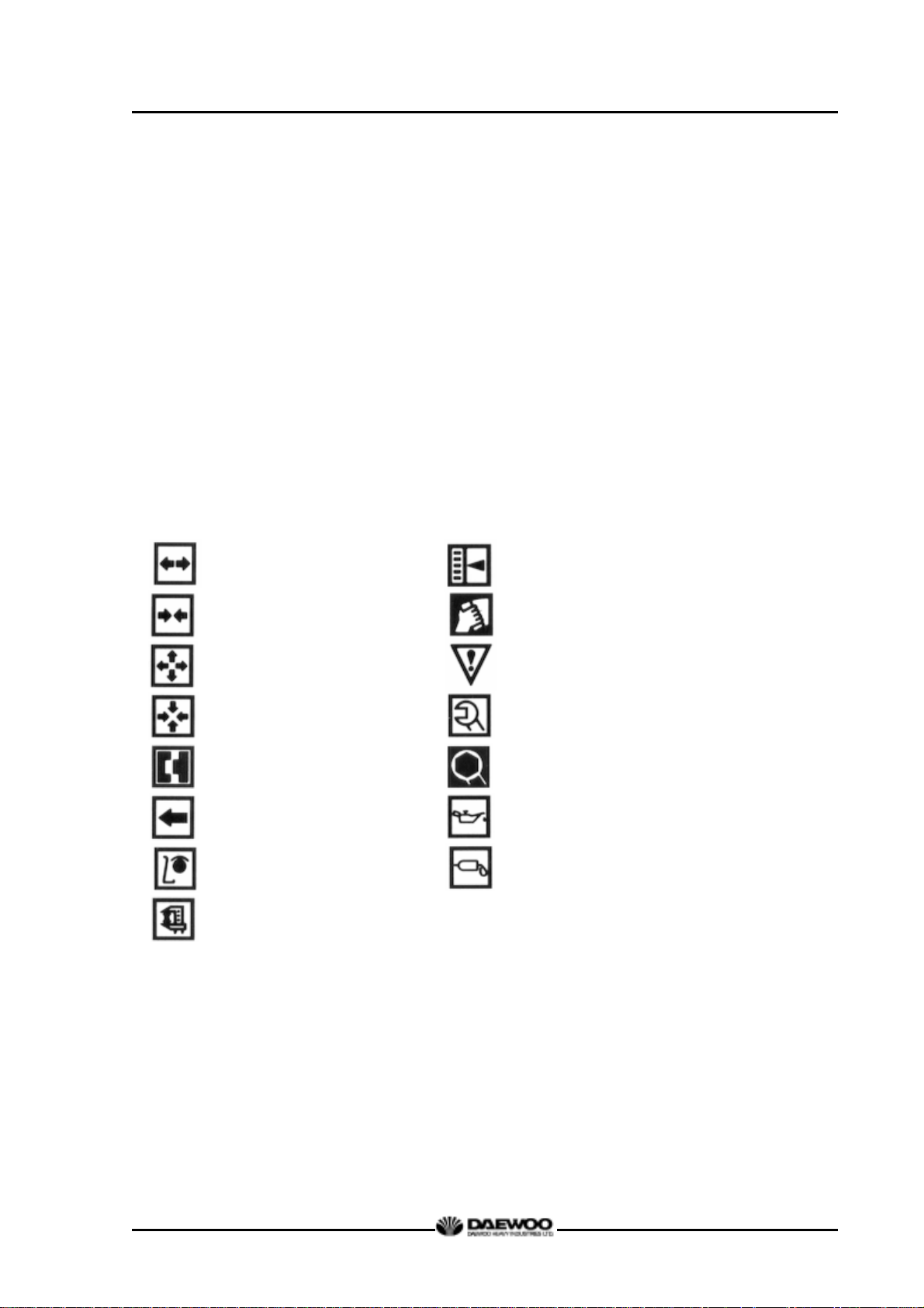
In this manual, the following symbols are used to indicate the type of service operations to be
performed.
Removal Adjustment
Installation Cleaning
Disassembly Pay close attention-Important
Reassembly Tighten to specified torque
Align the marks Use special tools of manufacturer's
Directional Indication Lubricate with oil
Inspection Lubricate with grease
Measurement
During engine maintenance, please observe following instructions to prevent environmental
damage;
z Take old oil to an old oil disposal point only.
z Ensure without fail that oil and diesel fuel will not get into the sea or rivers and
canals or the ground.
z Treat undiluted anti-corrosion agents, antifreeze agents, filter element and
cartridges as special waste.
Printed in Jan. 2001 PS-MMA0415-E1A
Page 3

D1146/D1146TI/DE08TIS
MAINTENANCE MANUAL
z The regulations of the relevant local authorities are to be observed for the
disposal of spent coolants and special waste.
If you have any question or recommendation in connection with this manual, please do not
hesitate to contact our head office, dealers or authorized service shops near by your location
for any services.
For the last, the content of this maintenance instruction may be changed without notice for
some quality improvement. Thank you.
DAEWOO Heavy Industries & Machinery LTD.
Feb. 2001
Printed in Jan. 2001 PS-MMA0415-E1A
Page 4

MAINTENANCE MANUAL
CONTENTS
1. GENERAL INFORMATION
1.1 General Repair Instructions 1
1.2. Engine Specific Character 2
1.3. Engine Specifications 4
1.4. Engine Assembly 8
2. MAJOR MAINTENANCE
2.1. Preventive Maintenance 13
2.2. Diagnosis and Remedy 22
2.3. Engine Inspection 32
3. MAINTENANCE
3.1. Engine Disassembly 33
3.2. Inspection and Measurement on Major Parts 48
3.3. Reassembly 69
3.4. Breaking in 96
D1146/D1146TI/DE08TIS
4. MAINTENANCE OF MAJOR COMPONENTS
4.1. Cooling System 98
4.2. Lubrication System 102
4.3. Fuel Injection Pump 106
4.4. Turbocharger 122
5. Special Tool List 132
● Appendix 134
● WORLDWIDE NETWORK
Printed in Jan. 2001 PS-MMA0415-E1A
Page 5

D1146/D1146TI/DE08TIS
MAINTENANCE MANUAL
1. GENERAL INFORMATION
1.1. General Repair Instructions
1. Before performing service operation, disconnect the grounding cable from the battery
for reducing the chance of cable damage and burning due to short-circuiting.
2. Use covers for preventing the components from damage or pollution.
3. Engine oil and anti-freeze solution must be handled with reasonable care as they
cause paint damage.
4. The use of proper tools and special tools where specified is important to efficient and
reliable service operation.
5. Use genuine DAEWOO parts necessarily.
6. Used cotter pins, gaskets, O-rings, oil seals, lock washer and self-lock nuts should
be discarded and new ones should be prepared for installation as normal function of
the parts can not be maintained if these parts are reused.
7. To facilitate proper and smooth reassemble operation, keep disassembled parts
neatly in groups. Keeping fixing bolts and nut separate is very important as they vary
in hardness and design depending on position of installation.
8. Clean the parts before inspection or reassembly. Also clean oil ports, etc. using
compressed air to make certain they are free from restrictions.
9. Lubricate rotating and sliding faces of parts with oil or grease before installation.
10. When necessary, use a sealer on gaskets to prevent leakage.
11. Carefully observe all specifications for bolts and nuts torques.
12. When service operation is completed, make a final check to be sure service has
been done property.
1
Printed in Jan. 2001 PS-MMA0415-E1A
Page 6
D1146/D1146TI/DE08TIS
MAINTENANCE MANUAL
1.2. Engine Specific Character
1.2.1. Toroidal combustion mode (D1146)
The D1146 engine is operated in the toroidal combustion mode that was developed by
this company with AVL Co. Australia.
The feature of this mode in the fundamental structure is that there are combustion
chambers in the centers of piston heads and swirling passages in the cylinder heads.
This swirling passages when intake stroke generates the strong swirling motion in the
combustion chambers by giving the intake air a big moment, and when compression
stroke, the special piston’s shapes causing very complicated and distorted flows by
means of eddy current and squashed flows will make the air and fuel mix more
smoothly.
Also, when explosion stroke, a considerable output increase came to be expected with
the accomplishment of nearly perfect combustion by the more smooth mixing of air and
fuel which was injected through multi-nozzles in the combustion chamber.
This engine by means of Toroidal Combustion Mode has the specific character such as
quiet and stable revolutional motion, multi-purpose application, economical fuel and oil
consumption, etc.
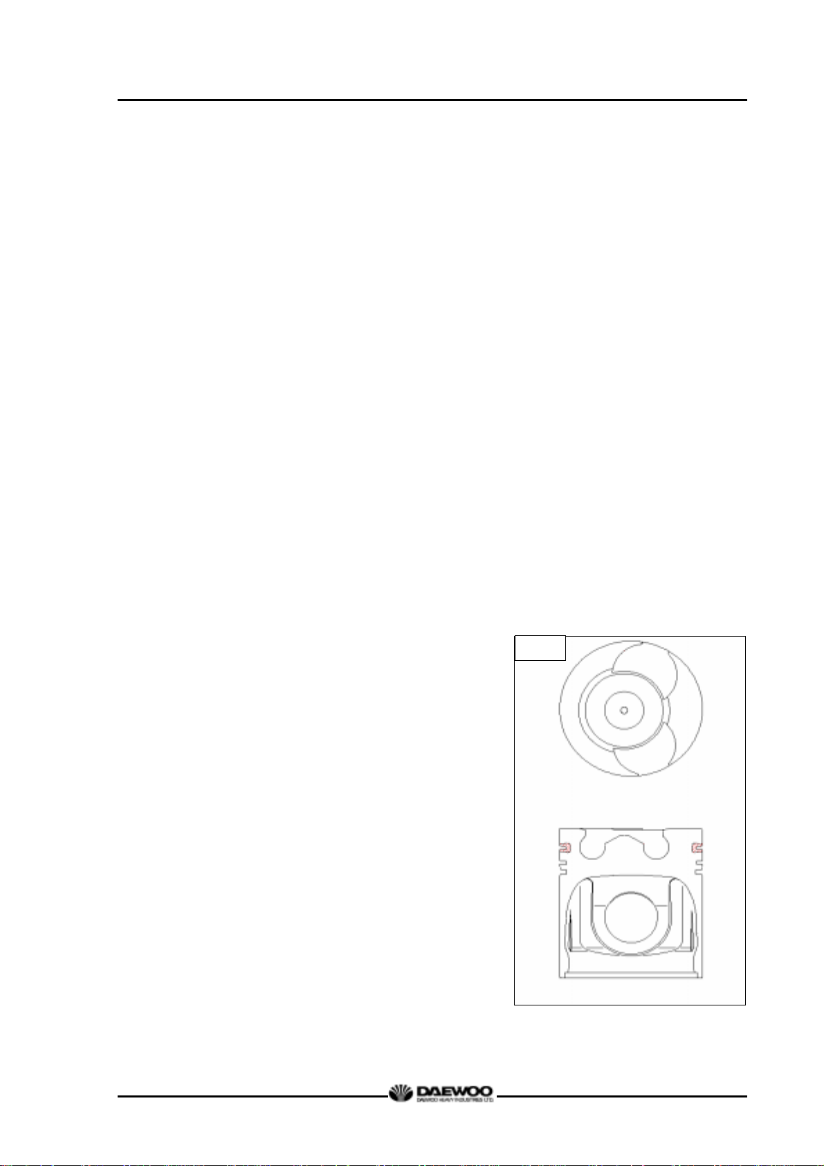
1.2.2. OMEGA combustion bowl (D1146TI, DE08TIS)
The OMEGA combustion bowl is a unit designed
to perform high efficiency, low emission
combustion. As the rim around the combustion
bowl port of the upper of the piston has been
machined in a smaller size than the interior of the
combustion bowl, strong swirl is produced in the
combustion bowl and strong squish flow makes
the fuel be mixed more sufficiently with air.
Due to the application of OMEGA combustion
system and optimal utilization of intake and
M1041A
exhaust port configuration within the cylinder
head, the D1146TI, DE08TIS diesel engines
discharge very low level of hazardous exhaust
gases such as smoke, nitrogen oxide,
hydrocarbon, or carbon monoxide and thus
ensure high performance and low fuel
consumption.
2
Printed in Jan. 2001 PS-MMA0415-E1A
Page 7
D1146/D1146TI/DE08TIS
MAINTENANCE MANUAL
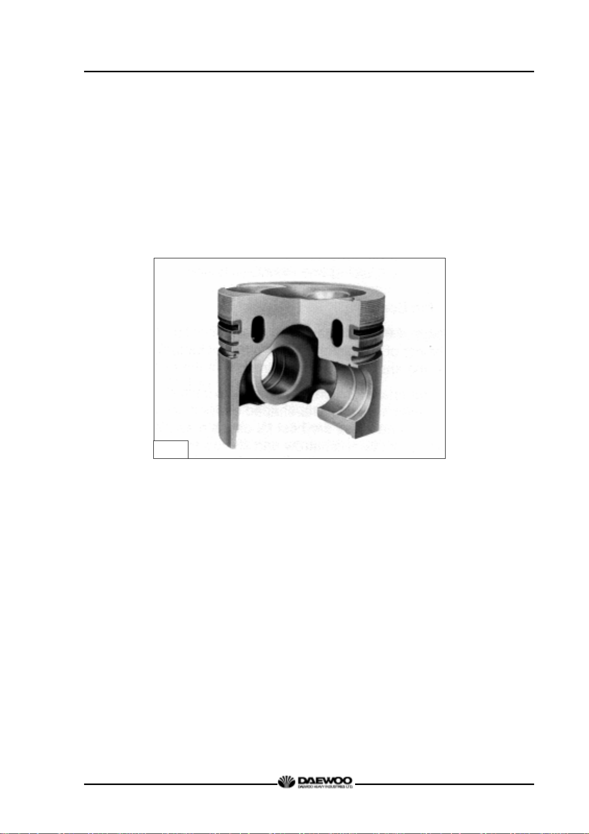
1.2.3. Oil gallery cooling type piston (DE08TIS)
Oil gallery cooling is used for the piston of DE08TIS diesel engine.
When thermal loading is high, piston cooling by means of an oil gallery in the crown is
normally necessary to prevent crown cracking and ring sticking. The design of the
gallery, the design and location of the oil spray nozzle and the quantity of oil flowing in
the gallery are critical in order to achieve the desired temperature reduction.
The cross section shape of the gallery should be designed to achieve sufficient oil
movement to maximize cooling efficiency.
M1255
3
Printed in Jan. 2001 PS-MMA0415-E1A
Page 8
D1146/D1146TI/DE08TIS
MAINTENANCE MANUAL
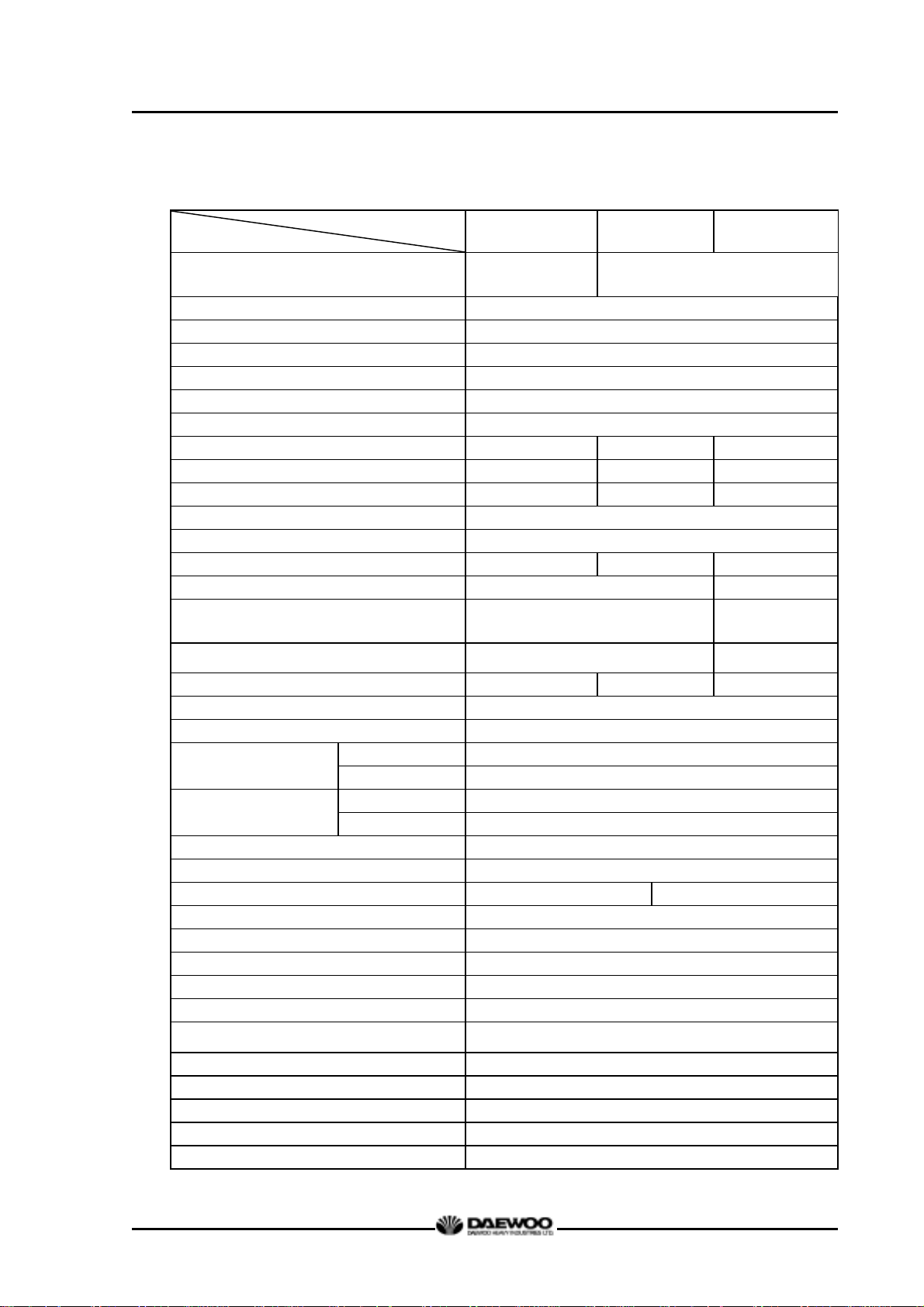
1.3. Engine Specifications
1.3.1. Specification
Engine Model
Items
Engine type
Combustion chamber type Direct injection type
Cylinder liner type Replaceable dry liner
Timing gear system Gear driven type
No. of piston ring Compression ring 2, oil ring 1
No. of cylinder-bore x stroke (mm)
Total piston displacement (cc) 8,071
Compression ratio 17.5 : 1 16.8 : 1 18.5 : 1
Engine dimension (length x width x height) (mm) 1,253x811.5x934.5 1,253x812.5x1,009 1,253x812.5x1,009
Engine weight (kg) 730 745 745
Rotating direction (viewed from flywheel) Counter clockwise
Fuel injection order 1 – 5 – 3 – 6 – 2 – 4
Fuel injection timing (B.T.D.C static)
Injection pump type Zexel in-line “AD” type Zexel in-line “P” type
Governor type
Injection nozzle type Multi-hole type (5 hole)
Fuel injection pressure (kg/cm2) 210 214 160/220
Compression pressure (kg/cm2) 28 (at 200 rpm)
Intake and exhaust valve clearance (at cold) (mm) 0.3
Intake valve
Exhaust valve
Lubrication method Full forced pressure feed type
Oil pump type Gear type driven by crankshaft
Oil filter type Paper element type Cartridge type
Lubricating oil capacity (max./min.) (lit) 15.5/12 or 20/17
Oil cooler type Water cooled
Water pump Centrifugal type driven by belt
Cooling Method Fresh water forced circulation
Cooling water capacity (engine only) (lit) 14
Thermostat type
Air compressor type & capacity (cc) Belt driven type, 220 or 300
Alternator voltage – capacity (V – A) 24 – 45 or 24-150
Starting Motor voltage – output (V - kW) 24 – 4.5
Air heater capacity (V – A) 22 – 95 (2.1kW)
Battery capacity (V - AH) 24 - 150
Open at
Close at
Open at
Close at
D1146 D1146TI DE08TIS
4 cycle in-line,
Water-cooled type
Naturally aspirated
6 – 111 × 139
15° 9° 3°
Mechanical governor
type(RLD)
16° (B.T.D.C)
36° (A.B.D.C)
46° (B.B.D.C)
14° (A.T.D.C)
Wax pallet type
(79 ∼ 94 °C or 83 ∼ 95 °C )
4 cycle in-line,
Water-cooled type
Turbo charged & intercooled
Mechanical
governor
type(RLD-J)
Multi-hole type
(7 hole)
4
Printed in Jan. 2001 PS-MMA0415-E1A
Page 9
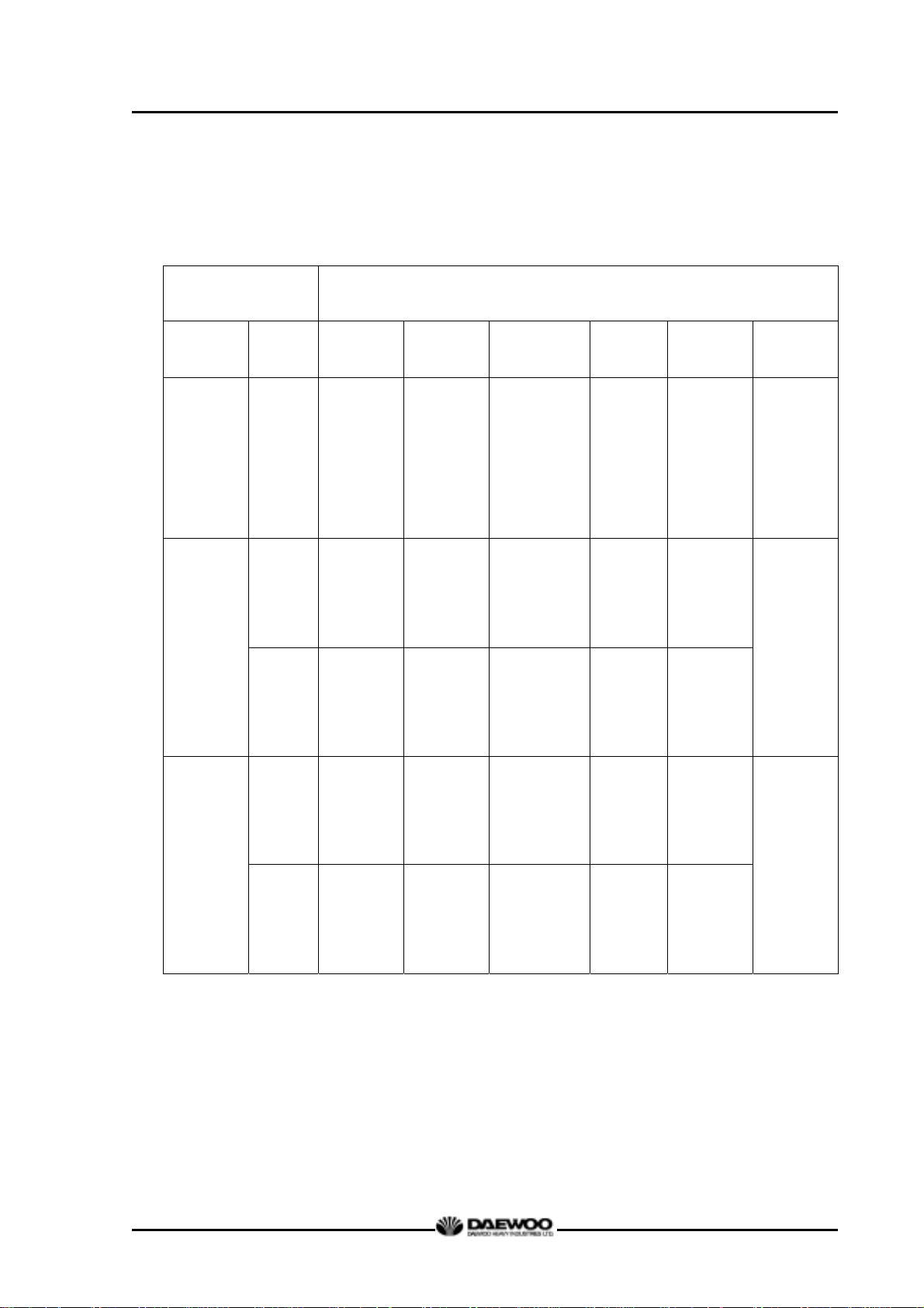
1.3.2. Engine power
Engine model Performance
D1146/D1146TI/DE08TIS
MAINTENANCE MANUAL
Production tolerance : ±5%
Model Suffix
EACBA
EACBB
EACBE
D1146
EACBH
EACBI
EACBK
EAPBA 9 205/2,200 75/1,400 600-650
D1146TI
EAPCA 9 215/2,300 82/1,400 600-650
Injection
timing
(BTDC°)
15 182/2,500 57.5/1,600 600-650 2750
Power
(PS/rpm)
Torque
(kg.m/rpm)
Low idle
(rpm)
High idle
(rpm)
2370
-
2,470
2250
-
2,350
Remark
EURO-I
ECPBA
ECPCA
DE08TIS
ECPBB
ECPCB
3 225/2,300 82/1,200 600-650 2,530
3 240/2,300 90/1,200 600-650 2,530
* Note : All data are based on operation without cooling fan at ISO 1585(SAE J1349).
5
EURO-II
Printed in Jan. 2001 PS-MMA0415-E1A
Page 10
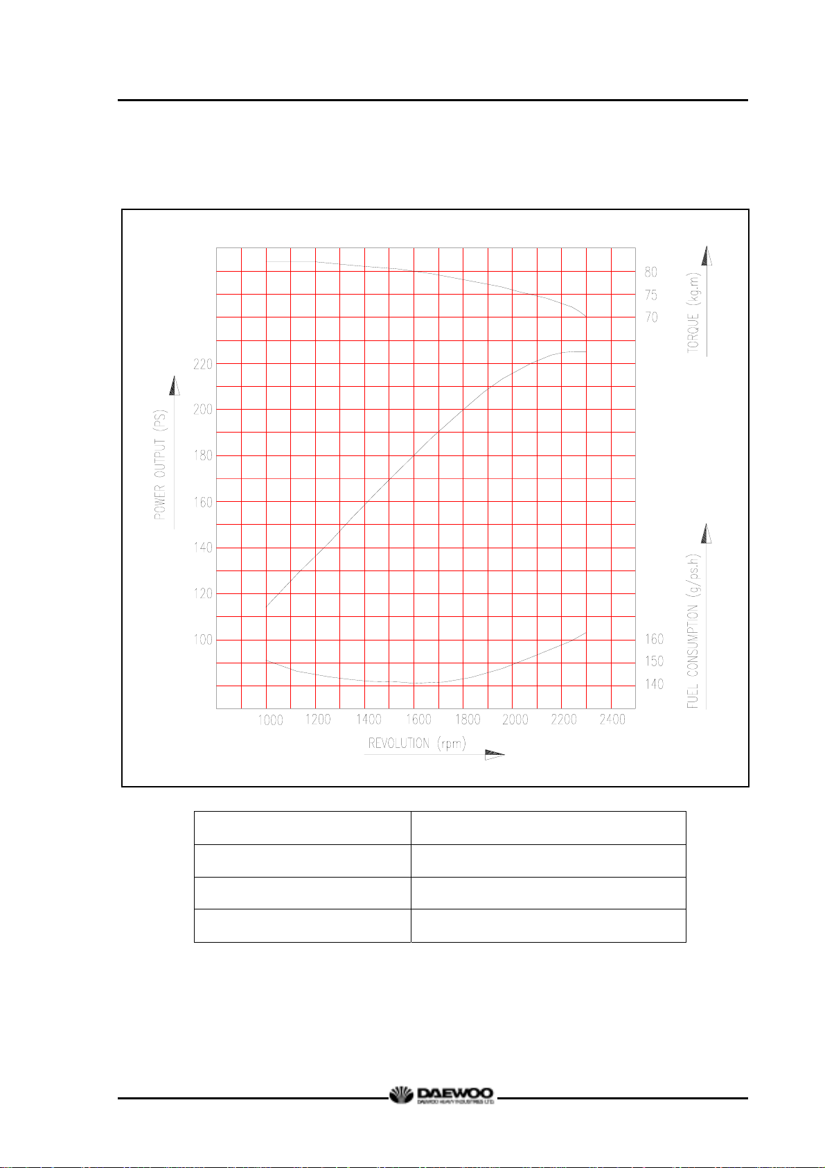
1.3.3. Performance curve (DE08TIS – 225PS)
D1146/D1146TI/DE08TIS
MAINTENANCE MANUAL
Performance ISO 1585(SAE J1349)
Output (max.) 165 kW (225PS) / 2,300 rpm
Torque (min) 804 N.m (82 kg.m) / 1,200 rpm
Fuel consumption (min) 192 g/kW.h (141 g / PS.h)
6
Printed in Jan. 2001 PS-MMA0415-E1A
Page 11
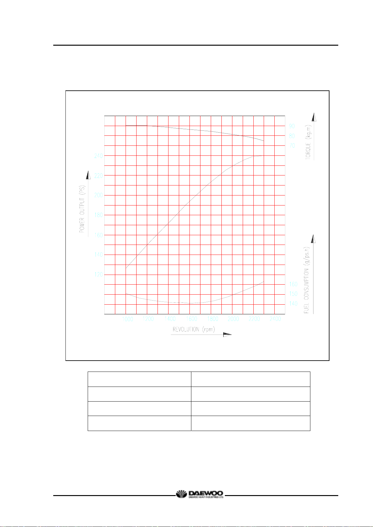
1.3.4. Performance curve (DE08TIS – 240PS)
D1146/D1146TI/DE08TIS
MAINTENANCE MANUAL
Performance ISO 1585(SAE J1349)
Output (max.) 176 kW (240PS) / 2,300 rpm
Torque (max.) 882 N.m (90 kg.m) / 1,200 rpm
Fuel consumption (min.) 192 g/kW.h (141 g / PS.h)
7
Printed in Jan. 2001 PS-MMA0415-E1A
Page 12
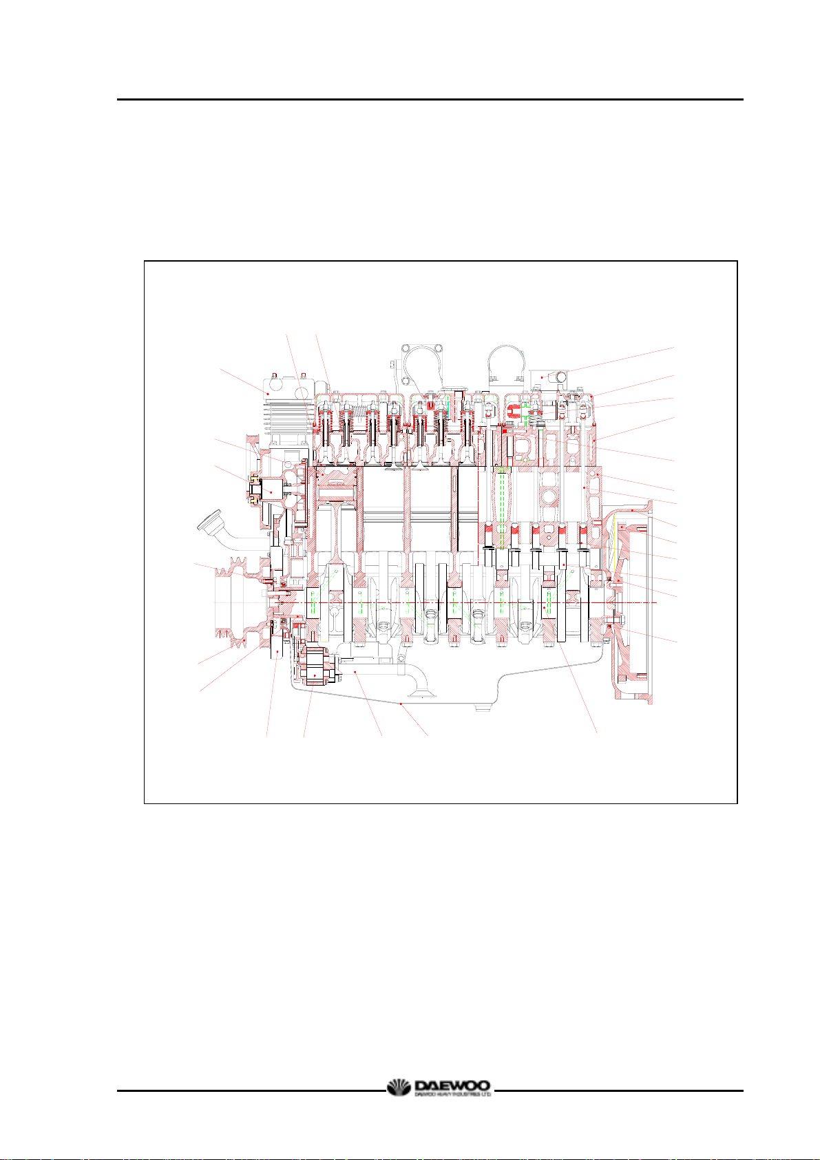
1.4. Engine Assembly
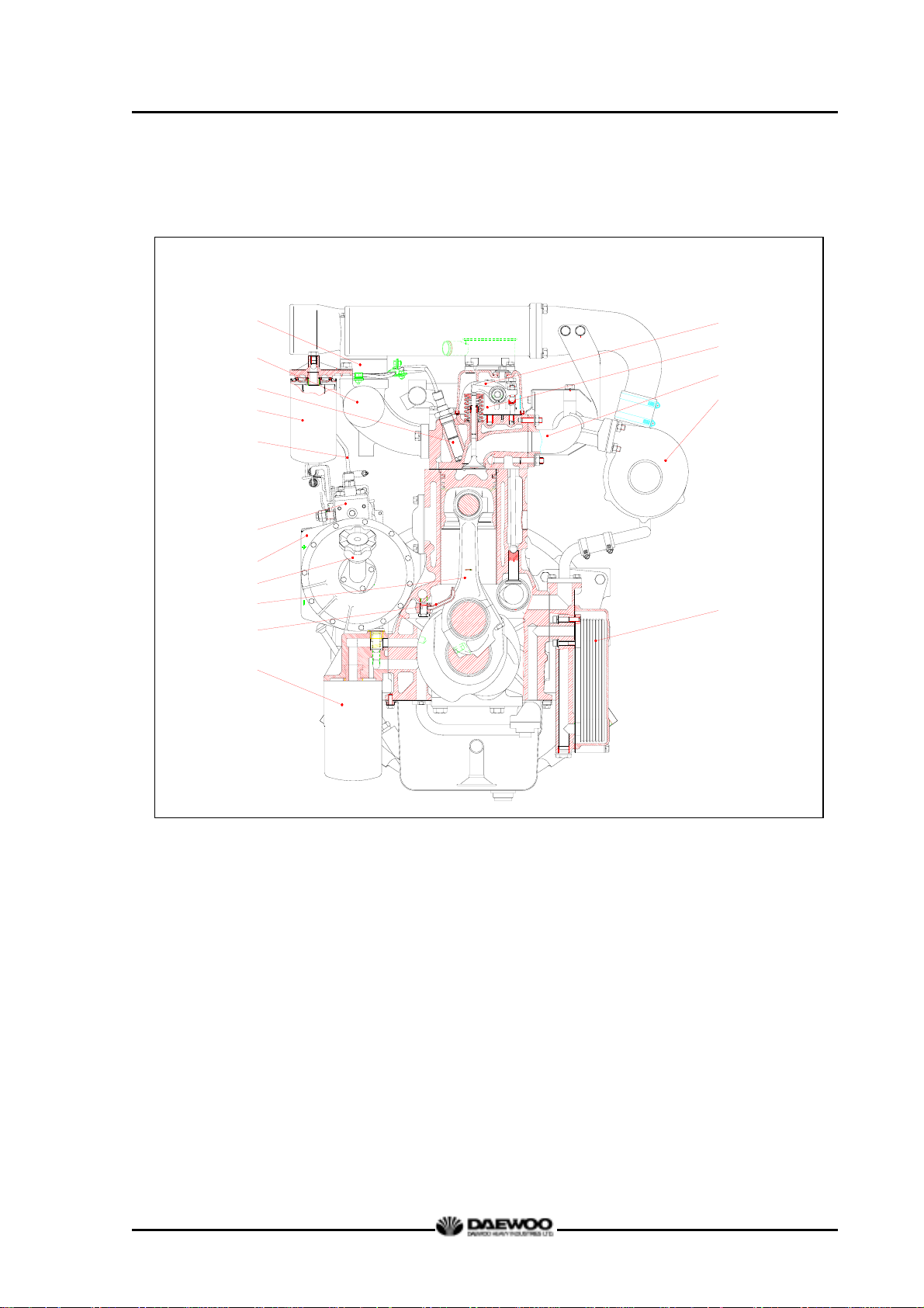
1.4.1. Engine sectional view (longitudinal)
5
4
3
2
D1146/D1146TI/DE08TIS
MAINTENANCE MANUAL
6
7
8
9
10
11
12
13
14
15
16
17
18
19
20
21
1
22
23
24 25 26
1 Water pump 2 Piston 3 Air compressor
4 Intake valve 5 Exhaust valve 6 Breather
7 Cylinder head cover 8 Exhaust valve spring 9 Cylinder head
10 Intake valve spring 11 Cylinder block 12 Push rod
13 Flywheel housing 14 Ring gear 15 Tappet
16 Cam shaft 17 Fly wheel 18 Oil seal (Rear)
19 Oil seal (Front) 20 Crank shaft pulley 21 Crank gear
22 Vibration damper 23 Oil pump 24 Oil suction pipe
25 Oil pan 26 Crank shaft
8
Printed in Jan. 2001 PS-MMA0415-E1A
Page 13
1.4.2. Engine sectional view (cross)
D1146/D1146TI/DE08TIS
MAINTENANCE MANUAL
5
4
3
2
1
10
11
12
13
14
15
6
7
8
9
16
1 Fuel injection pipe 9 Turbo charger
2 Fuel filter 10 Fuel injection pump
3 Fuel injection nozzle 11 Timing gear case
4 Intake manifold 12 Oil filler cap
5 Air heater 13 Connecting rod
6 Rocker arm 14 Oil spray nozzle
7 Rocker arm bracket 15 Oil filter
8 Exhaust manifold 16 Oil cooler
9
Printed in Jan. 2001 PS-MMA0415-E1A
Page 14
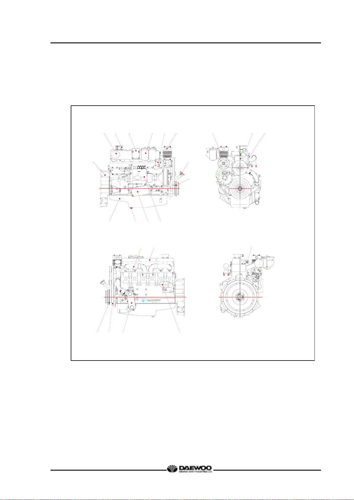
1.4.3. Engine Assembly Views
(1) D1146 (bus)
2
3 4 5 6 7
14
D1146/D1146TI/DE08TIS
MAINTENANCE MANUAL
15
16
1
11
10
12
17 18
13
8
9
23
20
19
21
22
1 Flywheel housing 8 Oil filler cap 16 Water pump
2 Intake manifold 9 Oil level gauge 17 Exhaust manifold
3 Breather 10 Oil pan 18 Cylinder head cover
4 Air pipe 11 Oil drain plug 19 Crank shaft pulley
(Air cleaner to intake manifold)
12 Oil filter 20 Vibration damper
5 Fuel filter 13 Fuel injection pump 21 Oil cooler
6 Power steering pump 14 Air compressor pulley 22 Starter
7 Air compressor 15 Thermostat 23 Cooling water pipe
10
Printed in Jan. 2001 PS-MMA0415-E1A
Page 15
D1146/D1146TI/DE08TIS
MAINTENANCE MANUAL
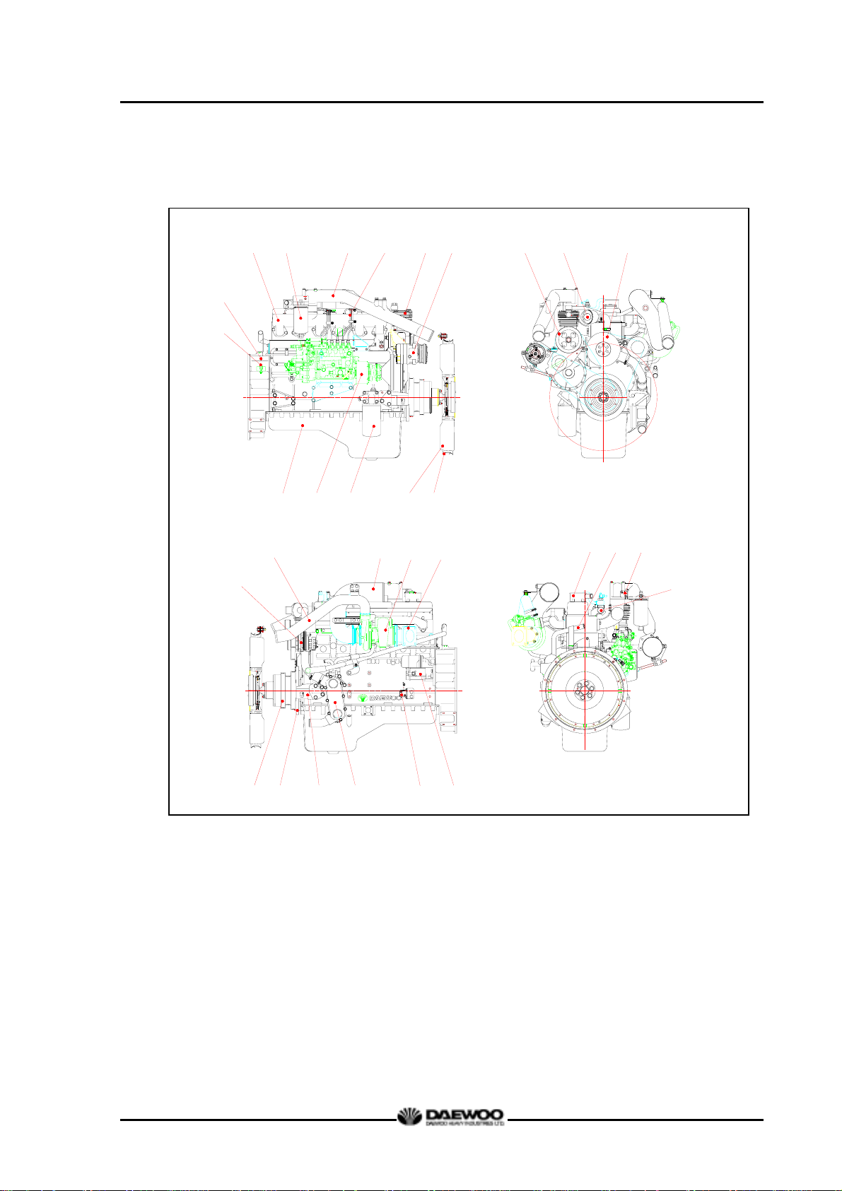
(2) DE08TIS (Truck)
34 5
2
1
18
17
9 10
678
11 12
19
13
20 21
14
15 16
28
29 30
31
22
23 24 25
26 27
Magnetic pick-up sensor
1
12 Cooling fan 21 Exhaust elbow
2 Flywheel housing 13 Cooling fan guide 22 Crank shaft pulley
3 Intake manifold 14 Air compressor pulley 23 Vibration damper
4 Fuel filter 15 Thermostat 24 Mounting bracket
5 Air pipe 16 Water pump 25 Oil cooler
(Intercooler to intake manifold)
17 Alternator 26 Starter relay
6 Fuel injection pipe 18 Air pipe 27 Starter
7 Air compressor
(Turbocharger to intercooler)
28 Breather
8 Air con. compressor 19 Air pipe 29 Water delivery pipe
9 Oil pan
(Air cleaner to turbocharger)
30 Air heater relay
10 Fuel injection pump 20 Turbocharger 31 Cooling water pipe
11 Oil filter
11
Printed in Jan. 2001 PS-MMA0415-E1A
Page 16
D1146/D1146TI/DE08TIS
MAINTENANCE MANUAL
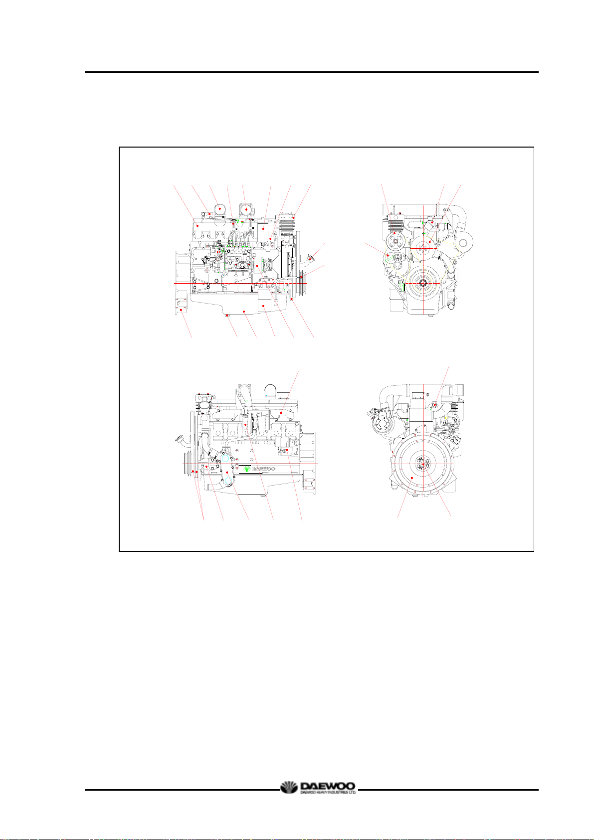
(3) DE08TIS (Bus)
192
11
3 4 5 6 7
12 13 14
15
21
8
16
18 19 20
17
10
27
22
23
24
25
26
28 29
1 Intake manifold 10 Oil level gauge 20 Water pump
2 breather 11 Flywheel housing 21 Exhaust manifold
3 Air pipe 12 Drain plug 22 Belt
(Intercooler to intake manifold)
13 Oil pan 23 Mounting bracket
4 Fuel injection pipe 14 Oil filter 24 Oil cooler
5 Air pipe 15 Fuel injection pump 25 Turbocharger
(Turbocharger to intercooler)
6 Fuel filter 17 Idle gear pulley 27
16 Vibration damper 26 Starter
Cooling water pipe
7 Power steering pump 18 Air compressor pulley 28 Fly wheel
8 Air compressor 19 Thermostat 29 Pilot bearing
9 Oil filler cap
12
Printed in Jan. 2001 PS-MMA0415-E1A
Page 17
D1146/D1146TI/DE08TIS
MAINTENANCE MANUAL
2. Major Maintenance
2.1. Preventive Maintenance
The preventive maintenance means that the operator performs the servicing of engine
to obtain long life and best performance from DAEWOO diesel engine.
2.1.1. Cooling Water
z Regarding the cooling water that is to be used for engine, the soft water not the hard
water must be used.
z The engine cooling water can be used diluting it with antifreezing solution 40% and
the additive for rust prevention (DCA4) 3 ~ 5 %.
z The density of above solution and additive must be inspected every 500 hours to
maintain it properly.
NOTE :
The proper density control of antifreezing solution and rust preventing
additive will be able to prevent the rusting effectively and maintain the stable
quality of engine. For the improper control might give the fatal damage to the
cooling water pump and cylinder liners, detail care is needed.
z Since D1146, D1146TI and DE08TIS (diesel engine of D1146 series) cylinder liner is
dry type, particularly the cooling water control should be applied thoroughly.
z The density of antifreezing solution and additive for rust prevention is able to be
confirmed by the cooling water test kit. (Fleetguard CC2602M or DAEWOO
60.99901-0038)
z How to use the cooling water test kit
(1) When the cooling water temp. of engine is in the range of 10 ~ 55 °C,
loosen the plug for cooling water discharge and fill the plastic cup about a half.
NOTE :
In taking the cooling water sample, if the water in auxiliary tank were taken, it
is hard to measure the accurate density. Take the cooling water sample
necessarily loosening the cooling water discharge plug.
(2) At the state of a test paper soaked in the sampled water, after taking the paper
out through water agitation, shake off the water.
13
Printed in Jan. 2001 PS-MMA0415-E1A
Page 18
D1146/D1146TI/DE08TIS
MAINTENANCE MANUAL
(3) Wait for about 45 sec. till the color change of test paper.
NOTE :
However, it should not elapse longer than 75 sec, and if it did, the hue would
change.
(4) Make the numerical value by comparing the test paper which hue has
changed with the color list of label on storage bottle.
(5) By comparing the hue changed into yellowish green or so with the green color
indication of test paper storage bottle, confirm the density. (Then, the density
indication must be in the hue range of 33% to 50%).
(6) The brown at the middle of test paper and the lower pink color indication
represent the additive state for rust prevention, and the proper range is that
the meeting numerical value of brown (vertical) and pink color (horizontal)
locates in the range of 0.3 to 0.8 at the color list of label on the test paper
storage bottle.
(7) In case of less than 0.3, replenish the additive for rust prevention (DCA4), and
in case of more than 0.8, pour out the cooling water about 50% and then
readjust the density after refilling with clean fresh water.
z Amount of Anti-freeze in winter
Ambient
Temperature (°C)
Over -10
-10
-15
-20
-25
-30
-40
Cooling water (%) Anti-freeze (%)
85
80
73
67
60
56
50
15
20
27
33
40
44
50
2.1.2. Fan belt
deteriorated.
z Check the fan belt for belt tension.
If belt tension is lower than the specified limit, adjust the tension by relocating the
alternator. (specified deflection: 10 ∼ 15 mm when pressed down with thumb)
z Use a fan belt of specified dimensions, and replace if damaged, frayed, or
14
Printed in Jan. 2001 PS-MMA0415-E1A
Page 19

2.1.3. Engine oil
z Check oil level with the oil level gauge and replenish if necessary.
z Check the oil level with the engine cooled. If the engine is warm, allow time for 5
∼ 10 minutes for oil drain into the crankcase before checking oil level. The oil level
must be between Max and Min. lines on the gauge.
z Engine oil should be changed at the specified intervals.
Oil filter cartridge should be changed simultaneously.
- First oil change : 1,000km(50 hr) operating
First oil change
(city bus, dump truck)
(express bus, cargo truck)
D1146/D1146TI/DE08TIS
MAINTENANCE MANUAL
After 1,000km (50hr)
operation
D1146/TI every 10,000km Short-distance operation vehicle
DE08TIS every 20,000km
D1146/TI every 15,000km Long-distance operation vehicles
DE08TIS every 30,000km
z The following oils are also recommended
* If long oil change intervals are to be used, ACEA-E3 oil must be used.
2.1.4. Oil filter
z Check for oil pressure and oil leaks, and
repair or replace the oil filter if necessary.
z Change the oil filter cartridge simultaneously
at every replacement of engine oil.
Engine
model
D1146
D1146TI
DE08TIS
Recommend oil
Remark
SAE No. API No.
SAE 15W40 above CD or CE
SAE15W40
SAE10W40
ACEA-E2 or ACEA-E3
(API CH-4)
Oil filter head
Oil filter
(Cartridge)
G1081
15
Printed in Jan. 2001 PS-MMA0415-E1A
Page 20
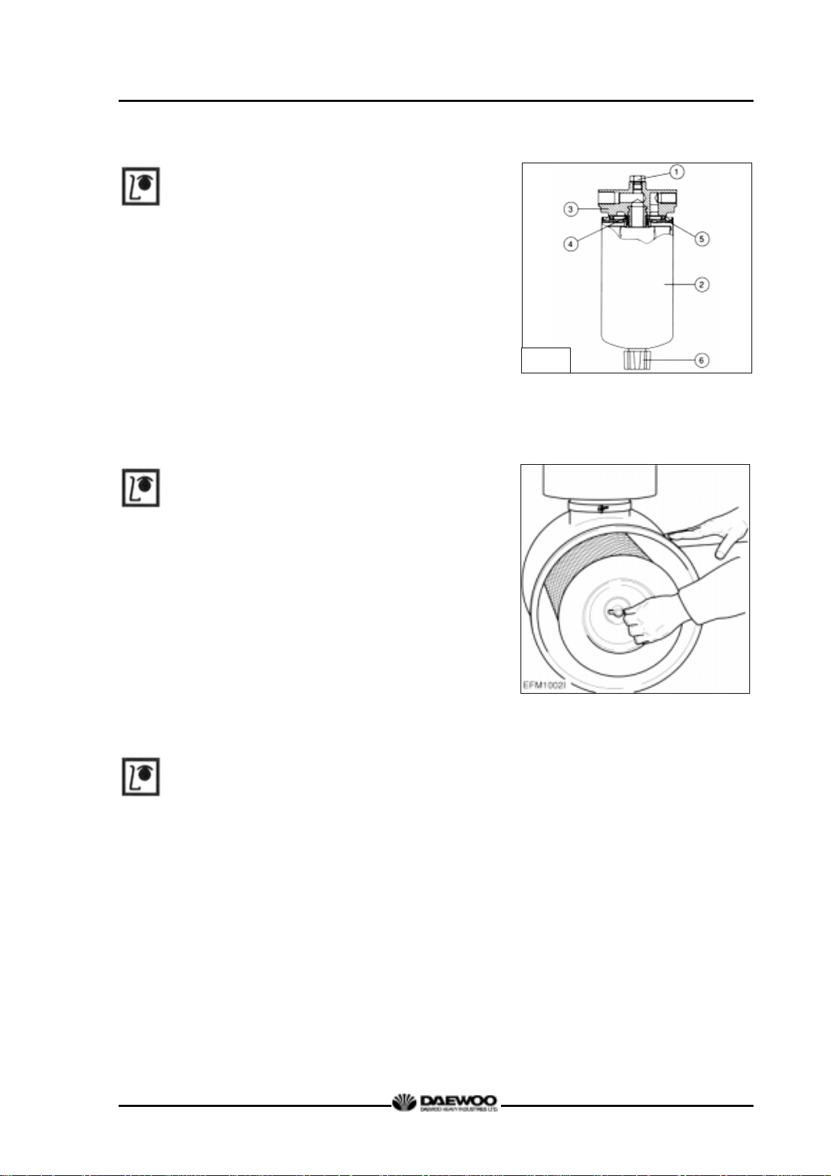
2.1.5. Fuel filter
z Drain water in cartridge with loosening
the
cock under filter manually (6) from time to
time.
D1146/D1146TI/DE08TIS
MAINTENANCE MANUAL
2.1.6. Air cleaner.
z In case that elements are deformed,
damaged or if the air cleaner has a crack,
replace it.
z By the definite interval, the elements must be
cleaned and replaced.
2.1.7. Intercooler
G1019
The intercooler is air to air type and has a large
cooling fan capacity. The intercooler life and
performance depends on the intake air
condition greatly. Fouled air pollutes and clogs
the air fins of intercooler. As a result of this, the
engine output is decreased and engine
malfunction is occurred. So you always check
whether the intake air systems like air filter
element are worn or polluted.
16
Printed in Jan. 2001 PS-MMA0415-E1A
Page 21
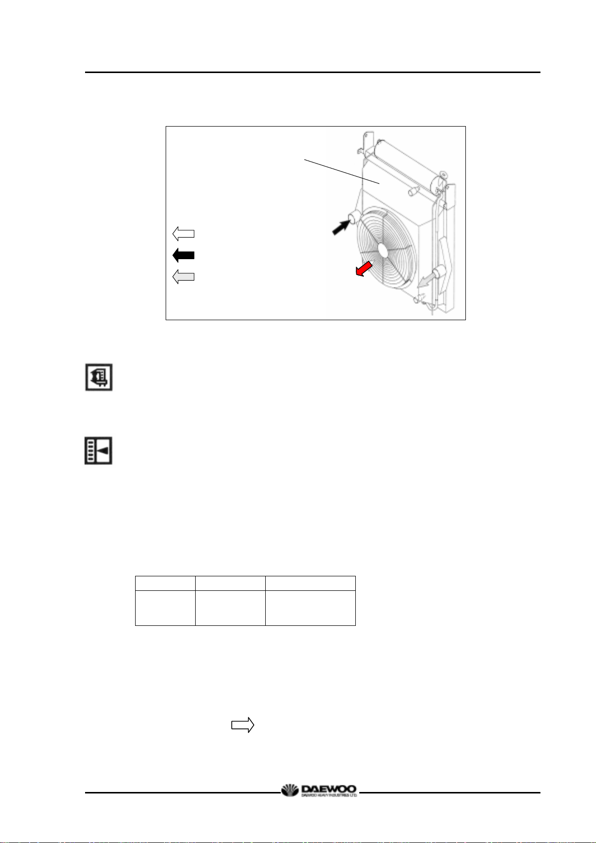
Air fl
D1146/D1146TI/DE08TIS
MAINTENANCE MANUAL
Air/air intercooler
with radiator
(combined radiator)
ow by cooling fan
Hot air by turbo charger
compressor
Cooled air to intake
manifold (max. 50°C)
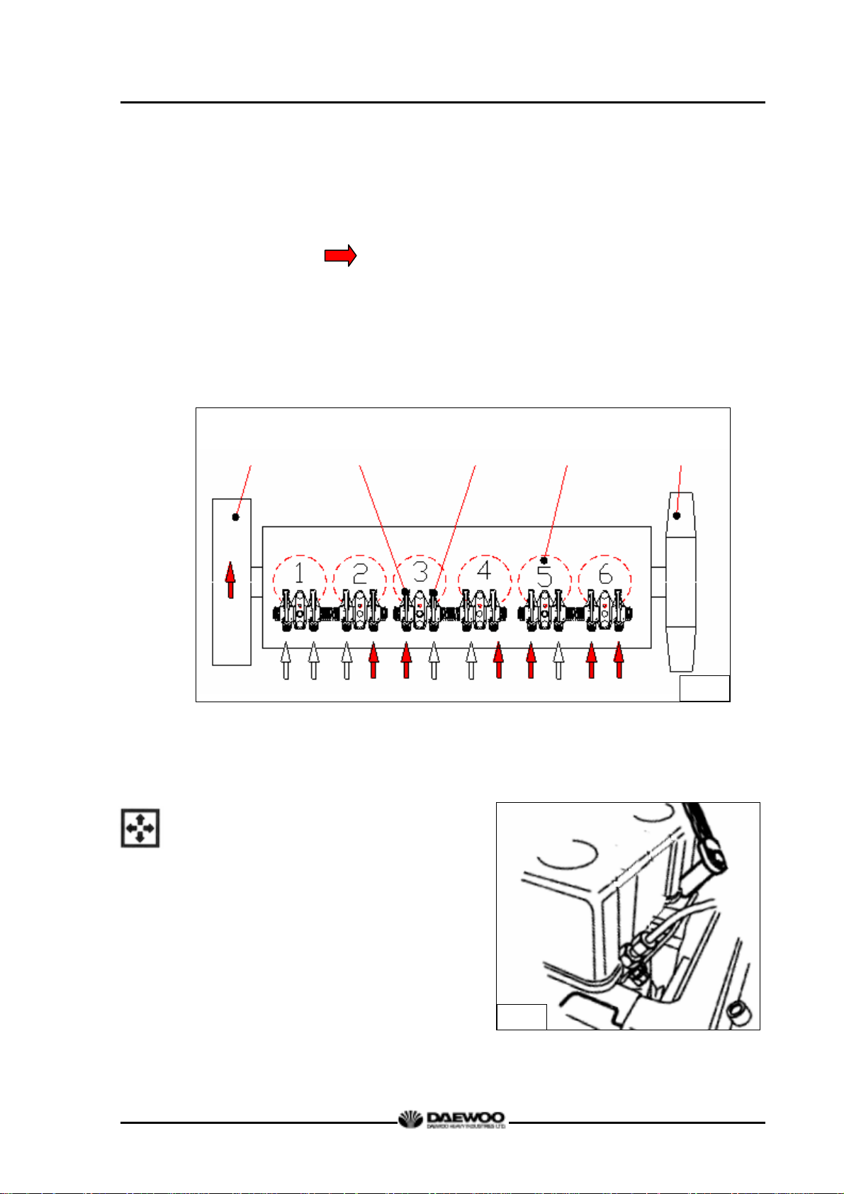
2.1.8. Valve clearance adjust procedure
z After letting the #1 cylinder's piston
come at
the compression top dead center by turning
the crankshaft, adjust the valve clearances.
z Loosen the lock nuts of rocker arm
adjusting screws and push the feeler gauge
of specified value between a rocker arm and
a valve stem and adjust the clearance with
adjusting screw respectively and then tighten
with the lock nut.
z As for the valve clearance, adjust it when in
cold, as follows.
Model
D1146
D1146TI
DE08TIS
Intake Valve Exhaust Valve
0.3 mm 0.3 mm
1) Rotate the crankshaft to overlap the intake
and the exhaust valves of #6, then #1 cylinder
become the compression state of top dead
center.
2) Therefore adjust the valve clearance
corresponding to “ ” of lower figure.
At this time there are no force on the push
rods of #1 cylinder.
17
Printed in Jan. 2001 PS-MMA0415-E1A
Page 22
D1146/D1146TI/DE08TIS
MAINTENANCE MANUAL
3) Rotating the crankshaft by one revolution, #6
cylinder become the compression state of top
dead center.
4) Thereafter adjust the valve clearances
corresponding to “
” of lower figure.
5) After reinsuring the valve clearances,
retighten if necessary.
z No. 1 cylinder is located at the side where
flywheel was installed.
Flywheel
Intake Valve Exhaust Valve Cylinder No. Cooling Fan
2.1.9. Cylinder compression pressure
z Stop the engine after warming up,
and
take out nozzle holder assembly.
G1048
G1067
18
Printed in Jan. 2001 PS-MMA0415-E1A
Page 23
D1146/D1146TI/DE08TIS
MAINTENANCE MANUAL
z Install the special tool (compression
gauge adapter) at the nozzle holder
hole, and connect the compression
pressure gauge there.
Standard value 28kg/cm
2
over
Limit value 24kg/cm2
Difference
between each cylinder
Within ± 10 %
♦ Condition : Water temperature 20°C,
Engine rotation 200rpm (10 rotations)
G1068
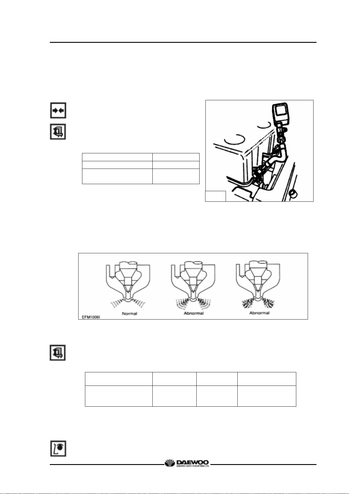
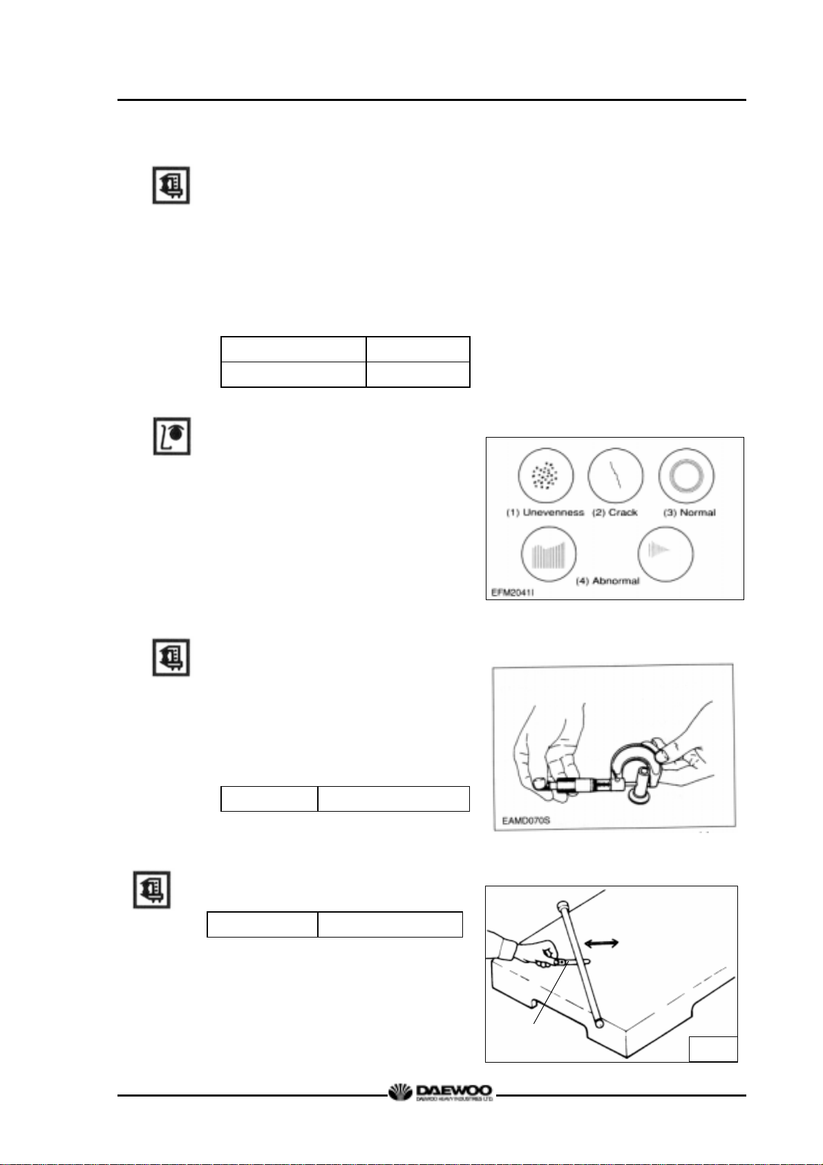
2.1.10. Injection nozzle
z Install a nozzle on the nozzle tester.
z If the inspected injection pressure is less than the specified value, adjust using
the adjusting shims.
Engine Model D1146 D1146TI DE08TIS
Opening pressure
z Check the atomizing state and replace it if abnormal.
2.1.11. Fuel injection pump
z Check the housing crack, damage etc. and replace it if abnormal.
210 kg/cm
19
2
214 kg/cm
1st : 160 kg/cm
2
2nd : 220 kg/cm
Printed in Jan. 2001 PS-MMA0415-E1A
2
2
Page 24
z Check if the idle operation and speed regulating lever's sealing is removed.
z The adjustment and testing of fuel injection pump should necessarily be done at
the test bench.
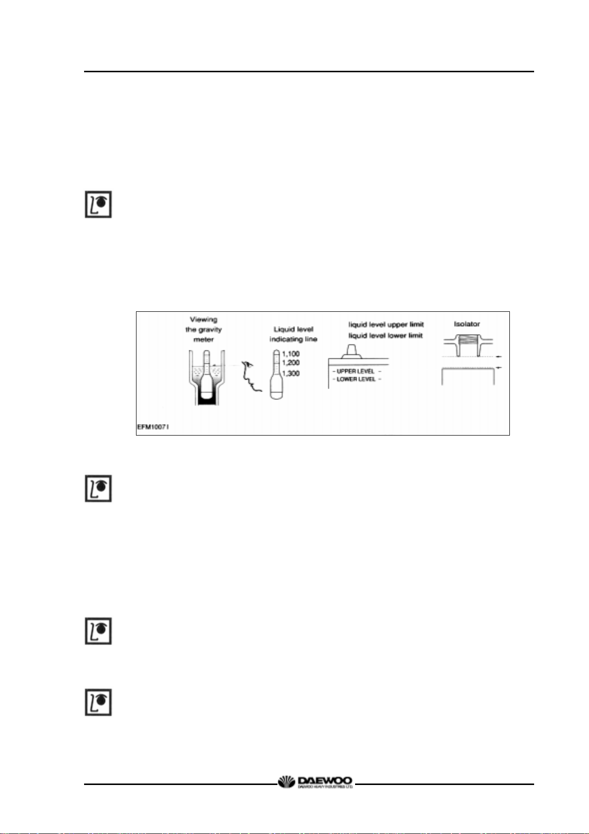
2.1.12. Battery
z Inspect for any leakage of electrolytic solution owing to battery crack, and
replace
the battery in case of poor condition.
z Inspect for amount of electrolytic solution, and replenish if insufficient.
z Measure the gravity of electrolytic solution, if less than specified value (1.12 ~
1.28), replenish.
D1146/D1146TI/DE08TIS
MAINTENANCE MANUAL
2.1.13. Air removal of fuel system
The suction room of fuel injection pump has the function of air removal continuously
during the operation through a relief valve.
In case that the suction room lacks fuel at all, for instance, in case of new installation
of injection pump, after loosening the air removing screws of cartridge filter
respectively, remove the air by operating the manual pump of fuel supply pump until
bubble will disappear.
2.1.14. Fuel supply pump
Every time of engine oil replacement, the fuel strainer installed at the fuel supply
pump should be removed and cleaned.
2.1.15. Turbocharger
The turbocharger needs not arty special equipment.
Every time of engine replacement, a leakage or clogging of oil pipes should be
inspected. Air cleaner should be maintained carefully for nut or foreign material not to
get in. Periodic inspection should be applied on the compressed air and exhaust gas
20
Printed in Jan. 2001 PS-MMA0415-E1A
Page 25
pipes, For leaking air will bring the overheat engine, an immediate repair must be
done.
During the operation that is surrounded by the dust and oil mixed air, frequent
cleaning must be done on the impellers. Tear down the impeller casing (attention: be
careful not to bend) and must clean with non-acid solvent solution. If necessary, use
plastic scraper If impeller is severely polluted, dip the impeller into solution and may
be better to clean it with stiff brush.
Then one thing to beware is to dip only impeller part and so do not support by
impeller but bearing housing.
2.1.16. Starting motor
In case of engine maintenance, clean pinion and ring gear thoroughly putting in the
fuel, and coat them with grease.
D1146/D1146TI/DE08TIS
MAINTENANCE MANUAL
Also, In case of washing engine (room) and so forth, inspect the wiring state being
careful for water not to get in.
21
Printed in Jan. 2001 PS-MMA0415-E1A
Page 26
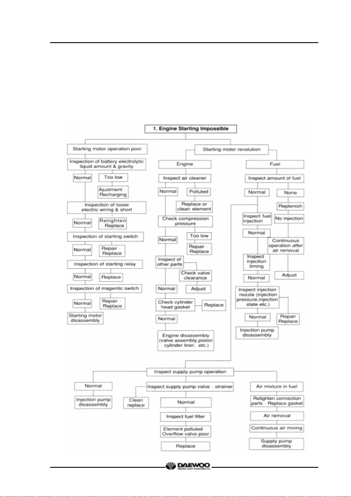
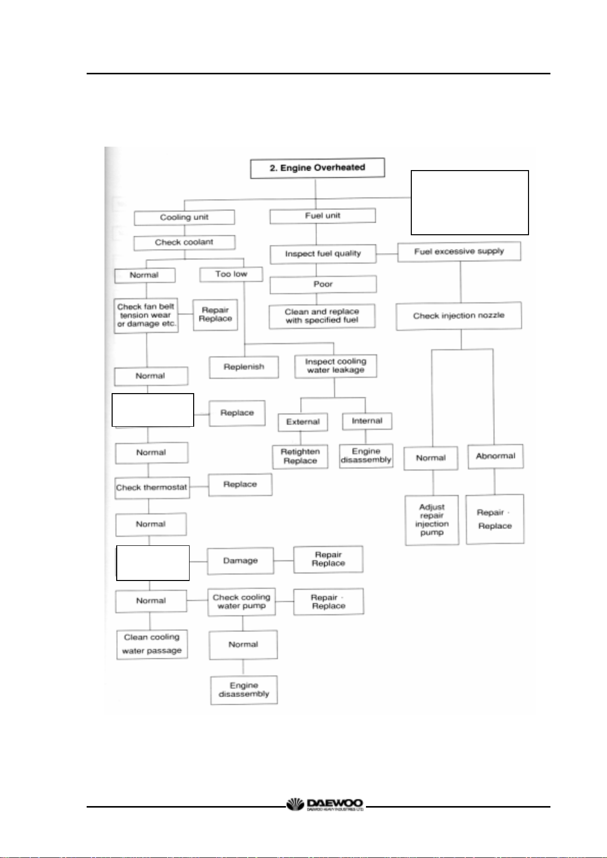
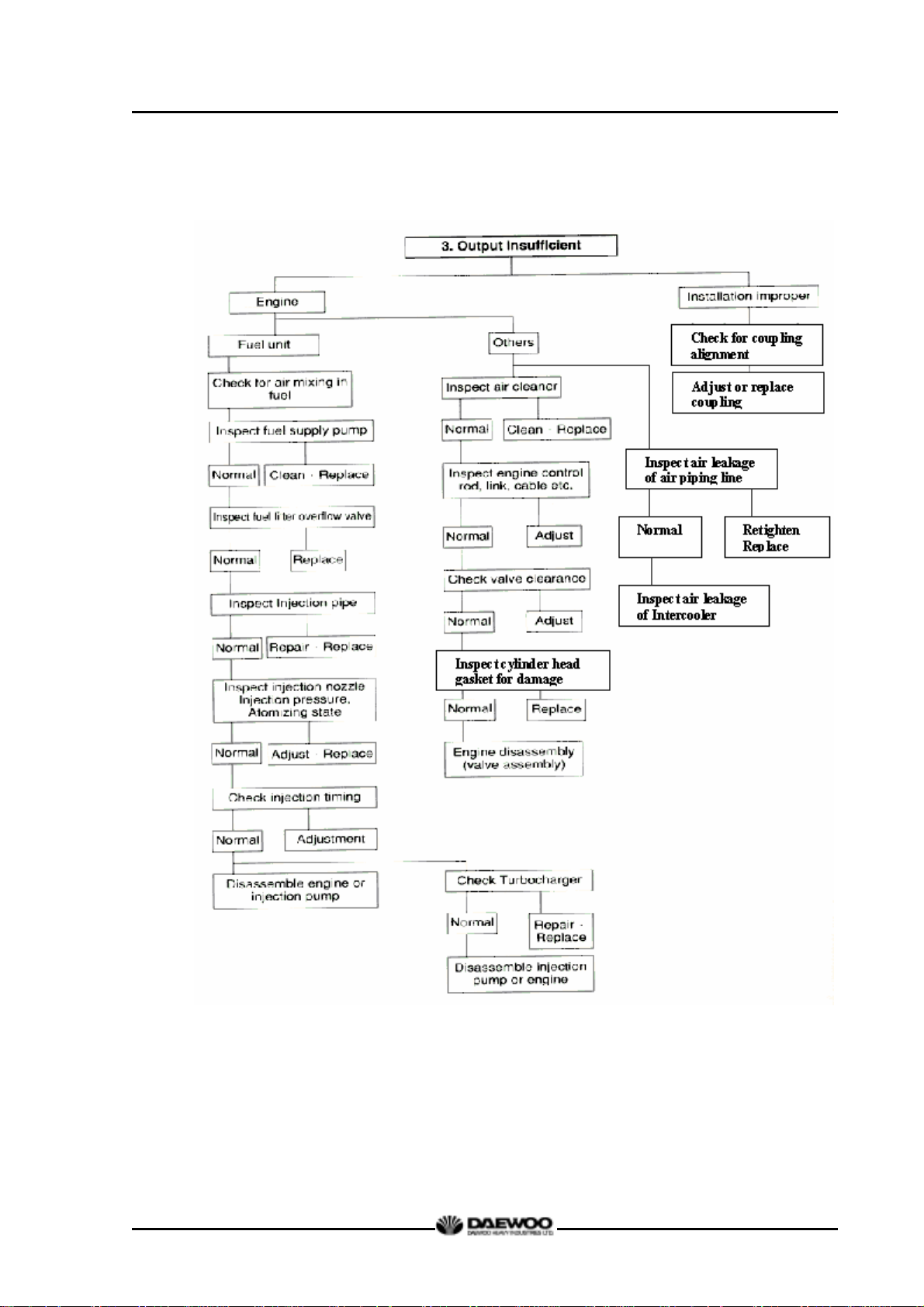
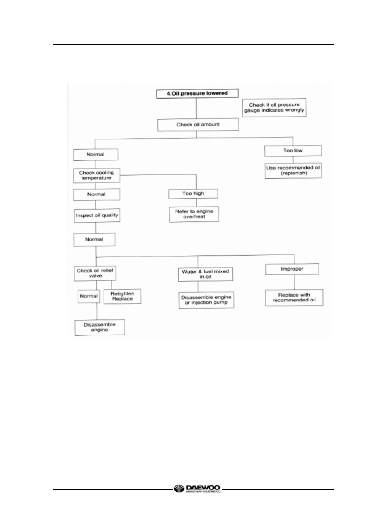
2.2. Diagnosis and Remedy
z The following description summarizes the probable cause of and remedy for
generall failure by item.
z Immediate countermeasures should be taken before a failure is inflamed if any
symptom is detected.
D1146/D1146TI/DE08TIS
MAINTENANCE MANUAL
22
Printed in Jan. 2001 PS-MMA0415-E1A
Page 27
D1146/D1146TI/DE08TIS
MAINTENANCE MANUAL
Operating state
1. Overload
2. Radiator core clogged
3. Continuous over-run
Check fresh
Radiator tank cap
Inspect
Radiator
23
Printed in Jan. 2001 PS-MMA0415-E1A
Page 28
D1146/D1146TI/DE08TIS
MAINTENANCE MANUAL
24
Printed in Jan. 2001 PS-MMA0415-E1A
Page 29
D1146/D1146TI/DE08TIS
MAINTENANCE MANUAL
25
Printed in Jan. 2001 PS-MMA0415-E1A
Page 30
D1146/D1146TI/DE08TIS
MAINTENANCE MANUAL
Causes according to operating conditions
1. Overload
2. Freqent use of low geae position at high speed
3. Freqent use of high geae position at low speed
4. Clutch slip
5. Too low tire inflation pressure
26
Printed in Jan. 2001 PS-MMA0415-E1A
Page 31

D1146/D1146TI/DE08TIS
MAINTENANCE MANUAL
Cause according to use conditions
1. Excessive oil infusing
2. continuous operation in low speed
or extremely cold state
27
Printed in Jan. 2001 PS-MMA0415-E1A
Page 32

D1146/D1146TI/DE08TIS
MAINTENANCE MANUAL
28
Printed in Jan. 2001 PS-MMA0415-E1A
Page 33

Condition Causes Remedies
1) Starting difficult
(1) Compression pressure lack z Valve's poor shut, stem
2) Idle operation abnormal
3) Engine output insufficient
(1) Continuous output
insufficient
(2) Output insufficient
when in acceleration
4) Overheating
D1146/D1146TI/DE08TIS
MAINTENANCE MANUAL
Repair or replace
distortion
z Valve spring damage Replace valve spring
z Cylinder head gasket's leak Replace gasket
z Wear of piston, piston ring
or liner
z Injection timing incorrect Adjust
z Air mixing at injection pump Remove air
z Valve clearance incorrect Adjust
z Valve tightness poor Repair
z Cylinder head gasket's leak Replace gasket
z Wear, stick, damage of
piston ring
z Injection timing incorrect Adjust
z Fuel injection amount
insufficient
z Nozzle injection pressure
improper or stuck
z Supply pump's function
lowered
z Fuel pipe system clogged Repair
z Air suction amount
insufficient
z Turbocharger poor Repair or replace
z Compression pressure
insufficient
z Injection timing incorrect Adjust
z Fuel injection amount
insufficient
z Injection pump timer's
function insufficient
z Nozzle infection pressure,
infection angle improper
z Supply pump's function
lowered
z Air intake amount
insufficient
z Engine oil insufficient or
poor
z Cooling water insufficient Replenish or replace
z Fan belt loosened, worn,
damaged
z Cooling water pump's
function lowered
z Water temp. regulator's
operation poor
z Valve clearance incorrect Adjust
z Exhaust system's resistance
increased
Adjust
Replace piston ring
Adjust injection pump
Adjust or replace
Repair or replace
Clean or replace air
cleaner
Disassemble engine
Adjust injection pump
Repair or replace
Repair, replace
Repair or replace
Clean or
replace air cleaner
Replenish or replace
Adjust or replace
Repair or replace
Replace
Clean or replace
29
Printed in Jan. 2001 PS-MMA0415-E1A
Page 34

5) Engine noisy
(1) Crankshaft
(2) Con.-rod and
Con.-rod bearing
(3) Piston, piston pin &
Piston ring
(4) Others
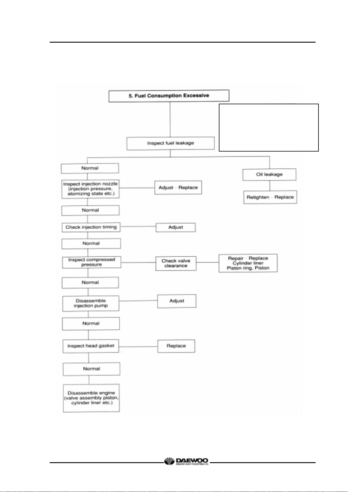
6) Fuel Consumption
Excessive
D1146/D1146TI/DE08TIS
MAINTENANCE MANUAL
Condition Causes Remedies
For noises arise compositely
such as rotating parts, lapping
parts etc., there is necessity to
search the cause of noises
accurately.
z As the wear of bearing or
crankshaft progress, the oil
clearances increase.
z Lopsided wear of crankshaft Grind or replace
z Oil supply insufficient due to
oil passage clogging
z Stuck bearing Replace bearing &
z Lopsided wear of con rod
bearing
z Lopsided wear of crank pi n Grind crankshaft
z Connecting rod distortion Repair or replace
z Stuck bearing Replace &
z Oil supply insufficiency as
clogging at oil passage
progresses
z Piston clearance increase
as the wear of piston and
piston ring progresses
z Wear of piston or piston pin Replace
z Piston stuck Replace piston
z Piston insertion poor Replace piston
z Piston ring damaged Replace piston
z Wear of crankshaft, thrust
bearing
z Camshaft end play
increased
z Idle gear end play increased Replace thrust washer
z Timing gear backlash
excessive
z Valve clearance excessive Adjust valve clearance
z Abnormal wear of tappet,
cam
z Supercharger inner part
damaged
z Injection timing incorrect Adjust
z Fuel injection amount
excessive
Replace bearing &
grind crankshaft
Clean oil passage
Grind
Replace bearing
grind crankshaft
Clean oil passage
Replace piston &
piston ring
Replace thrust bearing
Replace thrust plate
Repair or replace
Replace tappet, cam
Repair or replace
Adjust injection pump
30
Printed in Jan. 2001 PS-MMA0415-E1A
Page 35

7) Oil Consumption
Excessive
(1) Oil level elevated z Clearance between cylinder
(2) Oil level lowered z Looseness of valve stem &
(3) Oil leak z Looseness of connection
D1146/D1146TI/DE08TIS
MAINTENANCE MANUAL
Condition Causes Remedies
Replace
liner & piston
z Wear of piston ring, ring
groove
z Piston ring's damage, stick,
wear
z Piston ring opening's
disposition improper
z Piston skirt part damaged or
abnormal wear
z Oil ring's oil return hole
clogged
z Oil ring's contact poor Replace piston ring
guide
z Wear of valve stem seal Replace seal
z Cylinder head gasket’ s leak Replace gasket
parts
z Various parts' packing poor Replace packing
z Oil seal poor Replace oil seal
Replace piston,
piston ring
Replace piston ring
Correct position
Replace piston
Replace piston ring
Replace in set
Replace gasket, repair
31
Printed in Jan. 2001 PS-MMA0415-E1A
Page 36

R
r
t
D
R
A
v
2.3. Engine Inspection
2.3.1. Stopping engine
After checking the engine for any unusual condition at the idling speed, then turn the
key switch to stop the engine.
2.3.2. General engine inspection cycle
D1146/D1146TI/DE08TIS
MAINTENANCE MANUAL
О:Check&adjust●:Replace
Cooling
System
Lubrication
System
Intake &
Exhaust
System
Fuel
System
Inspection time(km)
Inspection
Check for leakage(hoses, clamp)
Check the water level
Check the V-belt tension
Change the coolant water
Check for leakage
Check the oil level gauge
Change the lubricating oil
eplace the oil filter cartridge
Check the leakage for intercoole
(hoses, clamp)
Clean and change
he air cleaner element
rain the water in separator
Clean the fuel strainer
of fuel feed pump
Check the fuel line leakage
Check fuel Injection timing
eplace the fuel filter cartridge
Check the injection nozzles
Daily
1,000 10,000 15,000 20,000 40,000
О
О
О
О
О
О
О
О
●
1st
●
1st
О
О
(О)
(О)
●
●
Remark
When
necessary
When
necessary
When
necessary
When
necessary
Engine
Adjust
Check the exhaust gas state
Check the battery charging
Check the compression pressure
djust Intake/Exhaust
alve clearance
О
О
О
*(О)Theengineoilchangeintervalisdeterminebyengineuseandoilgrade.
2.3.3. Use of original parts for repair and replacement
For engine is being mechanically harmonized with many parts, only when the original
parts that the manufacture recommends to use is used, the engine trouble would be
preventively maintained and capable to keep up the maximum performances.
For the analogous parts not the original parts are poor in qualities and gives illl
performances, it may rather bring early engine failure.
32
Printed in Jan. 2001 PS-MMA0415-E1A
Page 37

3. MAINTENANCE
3.1. Engine Disassembly
3.1.1. Heed at disassembly
z Before disassembly, the part shelf should be prepared for various tools and repair
parts.
z When assembling, clean empty hand should be used and clean environment
maintained.
z In case of storing the disassembled parts, each part should not touch each other.
z In case of disassembly, the parts should be laid in order.
3.1.2. Oil level gauge
z Pull out the oil level gauge.
D1146/D1146TI/DE08TIS
MAINTENANCE MANUAL
3.1.3. Cooling water
z Remove the radiator cap. Open the drain
valve at the radiator lower part to drain the
coolant as the right figure.
CAUTION:
When removing radiator filler cap while
the engine is still hot, cover the cap with a rag,
then turn it slowly to release the internal
steam pressure. This will prevent a person
from scalding with hot steam spouted out
from the filler port.
Drain valve
P1024a
z Remove the drain plug from the cylinder
block and drain out the cooling water into a
container.
Drain plug
33
Printed in Jan. 2001 PS-MMA0415-E1A
Page 38

3.1.4. Engine oil
z Remove the oil drain plug of oil pan and
pour the engine oil into the prepared
vessel.
3.1.5. Cooling fan
z Remove the flange fixing bolts, then take off
the flange and cooling fan.
D1146/D1146TI/DE08TIS
MAINTENANCE MANUAL
Drain plug
3.1.6. Belt
z Loosen the tension adjusting bolts of the
alternator and the idle pulley, and take off
the belts.
3.1.7. Thermostat
G1086
z Loosen the rubber hose connected to the
cooling water pipe and remove the
thermostat.
z Remove the rubber hose of the by-pass
line.
34
Printed in Jan. 2001 PS-MMA0415-E1A
Page 39

3.1.8. Starter
z Unscrew the starter fixing nuts and
remove the starter being careful not to
damage its gears.
3.1.9. Fuel filter
z Remove the hollow screws of filter and
tear down fuel supply and discharge
D1146/D1146TI/DE08TIS
MAINTENANCE MANUAL
rubber hose.
z Remove fuel filter fixing bolts and
disassemble the fuel filter.
(If the fuel filter is of cartridge type,
disassemble the cartridge element only.)
3.1.10. Breather
z Loosen the clamp screw to remove the
rubber hose.
3.1.11. Intercooler (D1146TI, DE08TIS)
z Tear down the various hoses and air pipes
from the inter cooler.
z Remove the intercooler fixing bolts and
tear it down.
P068
35
Printed in Jan. 2001 PS-MMA0415-E1A
Page 40

3.1.12. Alternator
z Remove the alternator fixing bolts and
take off the alternator.
3.1.13. Oil cooler
z Loosen the cooling water pump and the
rubber hose clamps of connected pipes,
and disassemble it.
D1146/D1146TI/DE08TIS
MAINTENANCE MANUAL
z Remove the oil cooler fixing bolts and
take off the oil cooler.
3.1.14. Oil filter
z Remo ve the oil filter fixing bolts and take
off the oil filter.
3.1.15. Power steering pump
z Remove the oil hose between power
steering oil pump and control unit of the
vehicle.
z Unscrew the power steering oil pump fixing
bolts and remove the power steering pump.
36
Printed in Jan. 2001 PS-MMA0415-E1A
Page 41

3.1.16. Air compressor
z Remove the oil pipe between cylinder
block and air compressor.
z Unscrew the air compressor fixing bolts
and take off the air compressor.
3.1.17. Idle pulley
z Unscrew the idle pulley fixing
bolts and take off the idle pulley
D1146/D1146TI/DE08TIS
MAINTENANCE MANUAL
3.1.18. Water pump
z Unclamp the rubber hose connected to
the oil cooler.
z Unscrew the water pump fixing bolts from
the cylinder block and take off the water
pump.
3.1.19. Cylinder head cover
z Remove the head cover fixing bolts and
lift the cylinder head cover.
37
Printed in Jan. 2001 PS-MMA0415-E1A
Page 42

3.1.20. Fuel injection nozzle
z Unscrew the fuel injection pipe between
the injection pump and nozzle and take
off the pipe.
z Install a special jig on the nozzle holder,
and then pull out the nozzle as striking
the hammer of the jig backwardly.
Take care not to damage the nozzle
at disassembly.
z Take out the seal ring from the nozzle
D1146/D1146TI/DE08TIS
MAINTENANCE MANUAL
hole of the cylinder head and discard it.
3.1.21. Turbo charger (D1146TI, DE08TIS)
z Remove the oil supply pipe and oil return
pipe between the turbo charger and the
cylinder block.
z Unclamp the rubber hose connected the
intercooler and air cleaner.
z Unscrew the turbo charger fixing nuts and
take off the turbo charger from the
exahust manifold.
3.1.22. Exhaust manifold
z Unscrew the exhaust manifold fixing nuts
and remove the heat shield from the
exhaust manifold.
z Then disassemble the exhaust manifold
and gasket.
z Scrap the used gasket.
38
Printed in Jan. 2001 PS-MMA0415-E1A
Page 43

3.1.23. Intake manifold
z Unscrew the intake manifold fixing bolts
and remove the intake manfold from the
cylinder head.
z Disassemble the intake manifold gasket
and discard it.
3.1.24. Cooling water pipe
z Unscrew the cooling water pipe fixing
bolts and remove the cooling water pipe
from the cylinder head.
z Remove the cooling water pipe gasket
Air heater
D1146/D1146TI/DE08TIS
MAINTENANCE MANUAL
Intake manifold
and finish the surface with a scraper.
CAUTION :
Be sure that piece of the gasket do
not come into the cooling water
passage.
3.1.25. Rocker arm
z Remove the rocker arm bracket fixing
bolts in reverse order (zigzag method) of
assembling and disassemble the rocker
arm.
z Take out the push rod upwards.
z Disassembly of rocker arm assembly
- Remove the snap ring fron the both
ends of rocker arm shaft by means of a
plier.
G1088
- Remove the washer, rocker arm,
bracket and spring from the rocker arm
shaf in sequence.
- Press out the rocker arm bush.
39
Printed in Jan. 2001 PS-MMA0415-E1A
G1056
Page 44

CAUTION :
When reassembling the bush, cool the
bush in dry ice and press the bush
while aligning the bush with the oil
hole of the rocker arm.
3.1.26. Cylinder head
z Remove the cylinder head bolts in the
reverse order of tightening but remove it
step by step.
First step : Loosen 1 ~2 threads
D1146/D1146TI/DE08TIS
MAINTENANCE MANUAL
Second step : Remove by loosening fully.
However, remove the total bolts
simultaneously by the step of 1 and 2.
z Lay the removed bolts orderly not to
damage the threads at all and store.
CAUTION :
Prevent a collision between the bolt
thread each other.
z Take out the cylinder head gasket and
scrap it.
z Remove the foreign residues from the
cylinder head surface and block surface.
CAUTION :
Try not to make any damage on the
G1089
contact surfaces.
z Disassembly of cylinder head
G1102
- Place the cylinder head on a individual
shelf.
- As pressing the valve spring with a
special tool, remove the cotter pin,
valve spring.
- Take out the intake and exhaust valves.
40
Compress the spring
Printed in Jan. 2001 PS-MMA0415-E1A
Page 45

D1146/D1146TI/DE08TIS
MAINTENANCE MANUAL
- For removal of the valve seat, apply arc
welding work to two points of valve seat
insert, and pull out the valve seat insert
with inner extractor.
3.1.27. Oil pan
z Unscrew the oil pan fixing bolts and
remove the oil pan.
z Remove the oil pan gasket and discard it.
3.1.28. Vibration damper
z Unscrew the vibration damper fixing
bolts in reverse sequence of installing
sequence and remove the vibration
damper assembly.
M1072
3.1.29. Timing gear case cover
z Disassemble the oil seal using an oil seal
removing jig.
z Remove the cover fixing bolts and
disassemble the cover from the timing
gear case.
G1090
41
Printed in Jan. 2001 PS-MMA0415-E1A
Page 46

3.1.30. Oil pump
z Unscrew the bracket fixing bolts of the oil
suction pipe.
z Unscrew the pipe fixing bolts of oil pump
and disassemble the suction and supply
oil pipe.
z Unscrew the oil pump fixing bolts, and
disassemble the oil pump.
3.1.31. Piston and connecting rod
z Remove the connecting rod cap bolts in
the reverse order of assembling but do
D1146/D1146TI/DE08TIS
MAINTENANCE MANUAL
same as the cylinder head bolt removal.
z Disassemble the upper/lower of
connecting rod caps by tapping lightly
with urethane hammer, and remove the
bearing.
z By pushing the connecting rod with
wooden bar from the direction of oil pan
toward cylinder head, disassemble the
piston assembly.
z The disassembled piston assembly
should be handled to prevent bumping
each other, and stored as the cylinder's
order.
z In order for connecting rod cap not to be
swapped, temporarily assemble to the
corresponding connecting rod.
<Disassembly of piston>
(1) Remove the snap rings by means
of a plier.
42
Printed in Jan. 2001 PS-MMA0415-E1A
Page 47

D1146/D1146TI/DE08TIS
MAINTENANCE MANUAL
(2) Heat the piston with a electric heater,
then take out the piston pin from the
piston as tapping it with a round
wooden bar.
(3) Remove the piston ring with a plier.
(4) Clean the piston thoroughly.
3.1.32. Cylinder liner
z Disassemble the cylinder liner with a
special tool or hand but be careful not to
generate any damage at cylinder block.
3.1.33. Cam shaft gear and idle gear
z Unscrew the camshaft gear fixing bolts
and remove the camshaft gear.
43
Printed in Jan. 2001 PS-MMA0415-E1A
Page 48

z Unscrew two bolts fxing the idle gear,
then remove the idle gear and its pin.
3.1.34. Fuel injection pump
z Disassembly the oil hose for lubrication.
z Remove the bolts and nuts of injection
pump flange.
z Unscrew the injection pump fixing bolts
and remove the injection pump by lifting
D1146/D1146TI/DE08TIS
MAINTENANCE MANUAL
it up.
z Remove the bracket fixing bolts of
injection pump, and disassemble by
pulling the injection pump backward.
3.1.35. Water chamber cover
z Unscrew the fixing bolts and remove the
water chamber cover.
z Remove the remnant gasket thoroughly.
3.1.36. Fly wheel
z Remove the flywheel fixing bolts and
disassemble it.
z The bolt removal is done by the reverse
order of assembling and by the steps.
44
Printed in Jan. 2001 PS-MMA0415-E1A
Page 49

3.1.37. Fly wheel housing
z Remove the flywheel housing fixing bolts
and disassemble the flywheel housing.
z Disassemble the oil seal of flywheel
housing.
3.1.38. Injection pump drive gear
z Unscrew the drive gear housing fixing
bolts and remove the drive gear
assembly.
D1146/D1146TI/DE08TIS
MAINTENANCE MANUAL
Oil seal
3.1.39. Timing gear case
z Remove the timing gear case
assembling bolts.
z By tapping lightly with a urethane
hammer the right and left back of timing
gear case's connecting part,
disassemble the timing gear case.
3.1.40. Bearing cap
z Remove the bearing cap assembling
G1097
bolts by the step in the reverse order of
assembling, and disassemble the
bearing cap. (Remove by the same way
as the cylinder head bolts' removal.)
z Disassembled bearing caps are kept laid
in order.
45
Printed in Jan. 2001 PS-MMA0415-E1A
Page 50

3.1.41. Crankshaft
z Assemble the bolts on the both side of
crankshaft temporarily.
z Connect the rope to the bolts and lift the
crankshaft by means of crane being
careful not to give any damage on it.
z In order for the disassembled crankshaft
to be prevented from bends or damage,
put it on the special lathe and store.
z Disassemble the metal bearings in turn
and store them.
D1146/D1146TI/DE08TIS
MAINTENANCE MANUAL
NOTES :
Do not mingle with the metal bearings
and bearing caps randomly. To prevent
mixing, temporarily assemble the metal
bearings to the corresponding bearing
caps in turn.
3.1.42. Camshaft and tappet
z In order for camshaft not to be damaged,
disassemble turning it.
z In order for the disassembled camshaft to
be prevented from bends or damage, put
it on the special lathe and store.
z Pull out the tappet.
z As required, pull out the camshaft bush
from the cylinder block by a press.
z Check for damage, scratch, wearing state
and if abnormal, tear down.
46
Printed in Jan. 2001 PS-MMA0415-E1A
Page 51

3.1.43. Oil spray nozzle (D1146TI, DE08TIS only)
z Remove the valve screws of oil spray
nozzle and disassemble it.
D1146/D1146TI/DE08TIS
MAINTENANCE MANUAL
47
Printed in Jan. 2001 PS-MMA0415-E1A
Page 52

3.2. Inspection and Measurement on Major Parts
3.2.1. Cylinder block
z Clean the cylinder block thoroughly, and check for any crack or damage.
z If there is any crack or severe damage, replace it and if there is minor one, correct
it.
z Check for any clogging or corrosion in the oil passage and water passage.
z Carry out a leakage test for any crack or air leaking. (Hydraulic test)
z Plug each cylinder block's water and oil discharge ports, and apply the air
pressure of about 4kg/cm
check if there is any leakage. (Water temperature : 70°C)
3.2.2. Cylinder head
2
to intake port and soak it in water for about 1 minute to
D1146/D1146TI/DE08TIS
MAINTENANCE MANUAL
(1) Cylinder head assembly & disassembly
1) Disassemble the cylinder assembly,
and put it on the shelf for assembly or
clean lathe.
CAUTION :
Prevent any damage to gasket's
contact surface of the cylinder
head.
2) Disassemble the cotter pin, spring,
spring seat pushing valve spring by a
special tool.
3) Pull out the intake and exhaust valves.
4) The disassembled parts are kept laid
in turn.
5) Disassemble the valve stem seal.
G1102
Compress the spring
6) By means of the special tool, punch,
pull out a valve guide.
48
Printed in Jan. 2001 PS-MMA0415-E1A
Page 53

(2) Inspection of cylinder head
1) Check for the cylinder head.
z Remove carbon from the cylinder head lower surface, and then should be
careful not to scratch the surface.
z Check any crack or damage that can not found by naked eyes through the
hydraulic or magnetic particle test.
2) Distortion of lower surface
D1146/D1146TI/DE08TIS
MAINTENANCE MANUAL
z As shown in figure, measure the
M1067
cylinder head's distortion at 6 directions
with horizontal ruler and clearance
gauge.
z If the measured value is beyond the
limit value, correct it by means of the
fine grinding paper or grinding machine.
z If it is beyond the max. allowable value,
replace the cylinder head
Lower face warpage and height
Warpage 0.2 mm or less 0.3 mm
Thickness : t
(reference)
Standard Limit
109.9 ∼ 110.1 mm
108.4 mm
G1093
3) Flatness
Check the flatness of the installing
surface of cylinder head's intake and
exhaust manifolds with horizontal ruler
and clearance gauge.
Standard Limit
0.05 mm 0.2 mm
4) The hydraulic test
The hydraulic test of cylinder head is
same as the cylinder block test.
49
Printed in Jan. 2001 PS-MMA0415-E1A
Page 54

t
D1146/D1146TI/DE08TIS
MAINTENANCE MANUAL
(3) Inspection of valve and valve guide
1) Valve
After cleaning valve with fuel, check it.
z Valve stem outer diameter
Measure the valve stem outer diameter
at 3 positions (top, middle, and bottom),
and check for any wear and if beyond
the limit value, replace the valve.
Description
Dimension
Intake valve stem φ8.950 ∼ φ8.970 mm
Exhaust valve stem φ8.935 ∼ φ8.955 mm
Standard Limit
φ8.93 mm
φ8.91 mm
z Valve seat contacting faces
Check the valve seat contact surface
for any crack and wear, and if
necessary, correct with grinding
paper, and if excessive, replace it.
z Valve head thickness
Measure the thickness of valve head
and if beyond the limit value, replace
the valve
Description
Dimension
Intake valve
Exhaust valve
Standard Limit
2.7 mm 1 mm or less
2.2 mm 1 mm or less
2) Valve guide
z Insert a valve into cylinder head and
measure the clearance between
valve guide and valve by valve
movement. If the clearance is
Measuring
Poin
excessive, measure the valve and
replace the excessively worn valve
M1076
50
Printed in Jan. 2001 PS-MMA0415-E1A
Page 55

D1146/D1146TI/DE08TIS
MAINTENANCE MANUAL
or valve guide.
Valve stem end play
Intake valve
Exhaust valve
Standard Limit
0.04 ∼ 0.07 mm
0.06 ∼ 0.09 mm
0.2 mm
0.25 mm
z Assemble the valve at cylinder
head's valve guide and see if it is
centered with the valve seat using a
special tool.
3) Valve seat
z Contacting face amount
As for the valve seat's wear, measure
the width of the contact surface with
intake valve seat and exhaust valve
seat. If beyond the limit value, replace
the valve seat.
z Assemble the valve at the valve seat
of the cylinder head, and check the
amount of depression of the valve
from the lower portion of the cylinder
head using a dial gauge.
Valve depression
Intake &
Exhaust
Standard Limit
0 ∼ 0.3 mm
0.55 mm
If the amount of depression is
beyond the specified limit, replace
the valve seat.
51
Printed in Jan. 2001 PS-MMA0415-E1A
Page 56

D1146/D1146TI/DE08TIS
MAINTENANCE MANUAL
z For the disassembling of valve seat,
by welding the welding bead to a
valve seat rotating tool or valve seat,
pull it out with a special tool.
M1072
z For the assembling of a new valve
seat, by putting it among the dry ices
of an ice box previously for about 2
hours for the cold shrinkage, and
press it in the cylinder head by a
special tool. (bench press)
z Apply valve lapping compound to the
valve head seating face on the valve
seat and lap the valve seat by turning it
until it is seated in position, then wipe
out the lapping compound.
4) Valve spring
z Visual check
Check the appearance of valve
spring and if necessary replace the
spring.
z Valve spring free length
Use a vernier caliper to measure the
valve spring free length.
If the measured value is less than
the specified limit, the valve spring
must be replaced.
(mm)
Spring free Length Standard
Intake valve
Exhaust
valve
Inner
Outer
64 mm
D1146/TI : 60
DE08TIS : 73.8
D1146/TI : 71
DE08TIS : 77.7
52
Printed in Jan. 2001 PS-MMA0415-E1A
M1078
Page 57

D1146/D1146TI/DE08TIS
MAINTENANCE MANUAL
z Valve spring inclination
Use a surface plate and a square to
M1079
measure the valve spring inclination.
If the measured value exceeds the
specified limit, the valve spring must
be replaced.
(unit : mm) Standard Limit
Valve Spring
Inclination
Less than 1.8 mm 2.7 mm
z Valve spring tension
Use a spring tester to measure the
M1080
valve spring tension if the measured
value is less than the specified limit,
the valve spring must be replaced.
Intake
valve
Exhaust
valve
Set Length
Valve Spring
Tension at 41mm
Set Length
Inner 38 mm
Outer 41 mm
Spring
force
70 kg ± 3%
D1 146/TI
: 28.6 kg
DE08TIS
: 38 kg
D1 146/TI
: 66 kg
DE08TIS
: 75kg
Limit
± 6 %
± 2kg
± 5 %
± 4kg
5) Assembling cylinder head
z Clean the cylinder head thoroughly.
z Replace the valve stem seal with
new one, and by means of a special
tool, press the stem seal into the
valve guide of cylinder head.
z Coat engine oil to valve stem and
valve guide and assemble the valve.
However, be careful for the damage
of valve stem seal.
53
Printed in Jan. 2001 PS-MMA0415-E1A
Page 58

z Install the lower seat of valve spring
to the valve guide of cylinder head.
z After putting inner, outer springs,
install the spring upper seat on it.
z Assemble the valve by inserting the
valve cotter pressing the valve
spring with a special tool.
z After installing the valve, check
whether the valve is correctly
installed or not tapping it lightly with
urethane hammer.
3.2.3. Rocker arm assembly
D1146/D1146TI/DE08TIS
MAINTENANCE MANUAL
(1) Disassembly
1) Disassemble the snap rings that are
located at both ends of rocker arm
shaft by a plier.
2) Disassemble in the order of washer,
rocker arm bracket, rocker arm spring,
rocker arm.
G1056
(2) Inspection of rocker arm assembly
1) Rocker arm shaft
z Rocker arm shaft run-out
Place the rocker arm shaft on two V
blocks and inspect the shaft for bend
using a dial gauge.
If the amount of this run-out is small,
press the shaft with a bench press to
correct the run-out Replace the shaft
if the measured value exceeds the
limit.
Limit
0.2 mm
54
Printed in Jan. 2001 PS-MMA0415-E1A
Page 59

D1146/D1146TI/DE08TIS
MAINTENANCE MANUAL
z Rocker arm shaft diameter
With an outside micrometer, measure
the rocker arm shaft diameter at the
point where the rocker arms have
been installed.
Replace the rocker arm if the amount
of wear is beyond the specified limit.
Standard Limit
φ23.978 ∼ φ23.959 mm φ23.75 mm
2) Rocker arm
z Visual check
Visually check the face of the
rocker arm in contact with the valve
stem end for scores and step wear.
If the wear is small, correct it with
an oil stone or grinding paper of
fine grain size. Rocker arm with a
considerable amount of step wear
should be replaced.
z Rocker arm bushing diameter
Measure the inside diameter of the
rocker arm bushing with an inside
micrometer or vernier calipers, and
compare the measured values with
the rocker arm shaft diameter. If the
clearance exceeds the limit, replace
M1087
either bushing or shaft, whichever
worn more.
Standard Limit
0.020 ∼ 0.093 mm
0.3 mm or less
55
Printed in Jan. 2001 PS-MMA0415-E1A
Page 60
D1146/D1146TI/DE08TIS
MAINTENANCE MANUAL
3) Tappet and push rod
z Clearance
Measure the clearance of the
tappet and tappet holes of the
cylinder block. If the value is
beyond the specified limit, replace
tappets.
Standard Limit
0.035 ∼ 0.077 mm
0.15 mm
z Visual check of tappet
Visually check the face of the
tappets in contact with the cam for
pitting, scores or cracks, and
replace if severely damaged. If the
amount of cracks or pitting is small,
correct with an oil stone or grinding
paper.
z Outside diameter of tappet
With an outside micrometer,
measure the tappet outside diameter
If the measured value is beyond the
limit, replace tappets.
Standard
φ19.944 ∼ φ19.965 mm
z Push rod run-out
Limit 0.3 mm or less
Use a feeler gauge to measure the
push rod run-out.
Roll the push rod along a smooth flat
surface as shown in the figure.
56
feeler gauge
M1084
Printed in Jan. 2001 PS-MMA0415-E1A
Page 61

)
4) Reassembling rocker arm assembly
Reassembling can be done in the reverse order of disassembling and following
things should be heeded
z Check the oil supply hole of rocker arm shaft for any clog and clean
thoroughly.
z Be careful not to occur any swap of position and reverse assembly.
3.2.4. Camshaft
(1) Camshaft end play
z Push the thrust plate toward the cam
gear.
D1146/D1146TI/DE08TIS
MAINTENANCE MANUAL
z With a feeler gauge, measure
the
clearance between the thrust plate
and camshaft journal.
z If the end play is excessive, replace
the thrust plate.
Feeler gauge
Standard Limit
0.28 ∼ 0.43 mm
0.6 mm
(2) Cam
z Cam lobe height
Intake 49.15 mm 48.85 mm
Cam lobe height
(C)
Cam journal diameter (A,B
Exhaust
Standard Limit
D1146/TI : 49.32mm
49.00 mm
DE08TIS : 49.35mm
φ57.86 ∼ φ57.88 mm φ57.52 mm
M1095
Use a micrometer to measure the
cam lobe height and journal
diameter.
If the measured number is less than
the specified limit, the camshaft
must replaced.
z Cam surface
57
Printed in Jan. 2001 PS-MMA0415-E1A
Page 62

D1146/D1146TI/DE08TIS
MAINTENANCE MANUAL
Inspect the cam face for scratch
or damage.
Slight step wear or damage on the
cam face may be corrected with oil
stone or oiled grinding paper. But,
replace if severely damaged.
(3) Cam shaft
z Clearance
between camshaft journal and camshaft bush
- With an outside micrometer,
measure the camshaft journal
diameter.
- Measure the inside diameter of
the camshaft bushing on the
cylinder block using a cylinder
bore indicator, and compare the
measured value with the
camshaft outside diameter to
determine the clearance.
M1090
<Clearance>
Standard Limit
0.12 ∼ 0.17 mm
0.24 mm
Replace the bushing if the
measured value is beyond the
specified limit.
z Run-out
Support the camshaft on two V
blocks and check for run-out
using a dial indicator. Correct or
replace the cam shaft if the
amount of run-out is beyond the
value indicating need for
servicing.
Standard Limit
58
Printed in Jan. 2001 PS-MMA0415-E1A
Page 63

3.2.5. Crankshaft
(1) Inspection of crankshaft
1) Defect check
z By naked eyes, check for any
scratch or damage on the
crankshaft journal and crank pin.
z By means of magnetic particle test
and color check, check the
crankshaft for any crack and if
found, replace it.
D1146/D1146TI/DE08TIS
MAINTENANCE MANUAL
0.05 mm 0.2 mm
2) Wear measuring
z With an outside micrometer measure
the diameter of the crankshaft journals
and pins in the directions as shown,
and compare the measured values to
determine the amount of wear.
z If the amount of wear is beyond the
limit, have the crankshaft ground and
install undersize bearings. However, if
the amount of wear is within the limit,
you can correct the wear using an oil
stone or oiled grinding paper of fine
grain size. (Be sure to use grinding
paper which has been immersed in
oil.)
Journal diameter
Pin diameter
Standard
φ83.966 ∼ φ83.988 mm φ83.000 mm
φ70.971 ∼ φ70.990 mm φ70.000 mm
59
Limit
Printed in Jan. 2001 PS-MMA0415-E1A
Page 64

D1146/D1146TI/DE08TIS
MAINTENANCE MANUAL
z In case that pin's wear is more than
the limit value, grind the crankshaft
journal and crank pin, and use the
undersized bearings.
Be sure to use grinding paper which
has been immersed in oil.
<Undersize bearings available>
Standard
0.25 (Inside diameter is 0.25 mm
lesser than the standard size.)
0.50 (Inside diameter is 0.50 mm
lesser than the standard size.)
"R" part's specified value
① Crank pin's "R" : 4.5
② Crank Journal "R" : 4
0
2.0−
0
2.0−
0.75 (Inside diameter is 0.75 mm
lesser than the standard size.)
1.00 (Inside diameter is 1.00 mm
lesser than the standard size.)
Undersize bearings are available in 4
different sizes as indicated above, and the
crankshaft can be reused through the
regrinding as described above.
CAUTION :
In case of regrinding, the grinding the "R" part of bearing end should
be correctly done and keep in mind to remove any jaws or coarse
surface absolutely.
3) Crankshaft run-out
z Support the crankshaft on V blocks.
z Turn the crankshaft with a dial
indicator placed on the surface plate
and take the amount of crankshaft
run-out.
Standard Limit
0.05 mm 0.1 mm
60
Printed in Jan. 2001 PS-MMA0415-E1A
Page 65

D1146/D1146TI/DE08TIS
MAINTENANCE MANUAL
(2) Crankshaft bearing and connecting rod
1) Visual check
Visually check the crankshaft bearing
and connecting rod bearing for scores,
uneven wear or damage.
2) Oil clearance between crankshaft and bearing (Method 1 : dial gauge)
z Main bearing clearance
Install the main bearing in the
cylinder block, tighten the bearing
cap to specified torque, then
measure the inside diameter.
Torque
30 kg.m
M1116
Compare the two values obtained
through measurement of main
bearing inside diameter with the
outside diameters of crankshaft
journals to determine the oil
clearance.
<Main bearing oil clearance>
Standard Limit
0.052 ∼ 0.122 mm
0.25 mm
z Connecting rod bearing clearance
Install the connecting rod bearing in
the connecting rod bearing cap,
tighten the connecting rod cap bolts
to the specified torque, then
measure the inside diameter.
Torque
18 kg.m
61
Printed in Jan. 2001 PS-MMA0415-E1A
Page 66

D1146/D1146TI/DE08TIS
MAINTENANCE MANUAL
Compare the two values obtained
through measurement of connecting
rod bearing inside diameter with the
outside diameters of crankshaft pins
to determine the oil clearance.
Standard Limit
0.034 ∼ 0.098 mm
0.25 mm
z If the clearance deviates from the
specified range, have the crankshaft
journals and pins ground and install
undersize bearings.
3) Oil clearance between crankshaft and bearing (Method 2 : plastic gauge)
z Assemble the crankshaft on the
cylinder block and put plastic gauge
on the journal and pin of crankshaft
and then after assembling bearing
cap, tighten the bolts at the specific
torque. Again after disassembling
the bearing cap by removing the
bolts, take out the flatted plastic
gauge and measure the width of
plastic gauge by means of plastic
gauge measuring scale. This is the
oil clearance.
z The oil clearance too can be
measured in the same manner
62
Printed in Jan. 2001 PS-MMA0415-E1A
Page 67

D1146/D1146TI/DE08TIS
MAINTENANCE MANUAL
4) Bearing spread and crush
z Inspection
Check to see that the bearing
requires a considerable amount of
finger pressure at reassembly
operation.
M1112
Spread
z Crankshaft bearing crush
Install the bearing and cap in the
cylinder block, retighten the bolts to
specified torque, unscrew out one
bolt completely, then measure the
clearance between the bearing cap
and cylinder block using a feeler
gauge.
Standard
0.19 ∼ 0.22 mm
z Connecting rod bearing crush
Install the bearing and cap in the
connecting rod big end, retighten
the bolts to specified torque,
unscrew out one bolt completely,
then measure the clearance
between the bearing cap and
connecting rod big end using a
feeler gauge.
Standard
0.3 ∼ 0.5 mm
63
Printed in Jan. 2001 PS-MMA0415-E1A
Page 68

D1146/D1146TI/DE08TIS
MAINTENANCE MANUAL
5) Crank shaft end play
z Assemble the crankshaft to the
cylinder block.
z With a dial gauge, measure
crankshaft end play.
Standard Limit
0.15 ∼ 0.325 mm
3.2.6. Piston assembly
(1) Disassemby of piston assembly
Disassemble piston according to the
disassembly process.
(2) Piston inspection
1) Visual check
Visually check the pistons for cracks,
scuff or wear, paying particular attention
to the ring groove.
2) Clearance between the piston and cylinder liner
z With an outside micrometer,
measure the piston outside diameter
at a point 13mm away from the lower
end of piston skirt in a direction at a
0.5 mm
Position of measuring
outside diameter
right angle to the piston pin hole.
Standard
φ110.883 ∼ φ110.897 mm
G1095
13 mm
z Using a cylinder bore gauge,
measure cylinder liner inside
diameter at 3 points (cylinder top
ring contacting face, middle, and oil
ring contacting face on BDC) in a
direction at an angle of 45°. Take the
mean value with the largest and
smallest values excepted.
64
Printed in Jan. 2001 PS-MMA0415-E1A
Page 69

D1146/D1146TI/DE08TIS
MAINTENANCE MANUAL
Standard Limit
φ111 ∼ φ111.022 mm φ111.122 mm
z The clearance is computed by
subtracting the piston outside
diameter from the cylinder liner inside
diameter. Replace either piston or
cylinder liner, whichever damaged
more, if the clearance is beyond the
specified limit.
Clearance between piston and liner
Standard
0.103 ∼ 0.139 mm
(3) Piston rings
1) Visual check
Replace the piston rings with new ones
if detected worn or broken when the
engine is overhauled.
2) Piston ring gap
z Insert the piston ring into the upper
portion of the cylinder liner bore so
that it is held at a right angle to the
cylinder liner wall.
z Measure the piston ring gap with a
feeler gauge.
Top ring
2nd ring
Oil ring
Standard Limit
0.40 ∼ 0.60 mm
0.40 ∼ 0.60 mm
0.30 ∼ 0.50 mm
1.5 mm
1.5 mm
1.5 mm
feeler gauge
z Replace piston rings with new ones if
M1104
the gap is beyond the limit
65
Printed in Jan. 2001 PS-MMA0415-E1A
Page 70

D1146/D1146TI/DE08TIS
MAINTENANCE MANUAL
3) Piston ring side clearance
z Fit the compression ring and oil ring in
the piston ring groove.
feeler gauge
z With a feeler gauge, measure side
clearance of each ring, and replace
either the ring or piston if the measured
value is beyond the specified limit.
Top ring
2nd ring
Oil ring
Standard Limit
- -
0.07 ∼ 0.102 mm
0.05 ∼ 0.085 mm
0.15 mm
0.15 mm
G1071
4) Piston ring tension
With a tension tester, measure piston
ring tension. Replace the piston ring if
the measured value is beyond the limit.
Top ring
2nd ring
Oil ring
Standard
2.58 ∼ 3.88 kg
1.81 ∼ 2.71 kg
3.57 ∼ 5.03 kg
(4) Piston pin inspection
1) Wear
Measure the amount of wear on the
M1105
piston pin at the points as shown. The
measured values are beyond the limit
(0.08 mm or greater), replace the pin.
Standard Limit
φ41.994 ∼ φ 42.000 mm φ 41.94 mm
66
Printed in Jan. 2001 PS-MMA0415-E1A
Page 71

D1146/D1146TI/DE08TIS
MAINTENANCE MANUAL
2) Clearance
Measure the clearance between the
piston pin and connecting rod bushing,
and replace either of them, whichever
damaged more, if the measured value is
beyond the limit.
M1106
Standard Limit
0.003 ∼ 0.015 mm
0.08 mm
3) Condition check
Check the engaged condition of the
piston and piston pin. If it is possible to
force the pin into the piston heated with
piston heater, the piston is normal. When
replacing the piston, be sure to replace
the piston pin together.
(5) Connecting rod inspection
1) Distorsion
Check the connecting rod for distortion.
As shown in the figure below, install the
connecting rod to the connecting rod
tester, and check for distortion using a
feeler gauge. If the connecting rod is
found distorted, never re-use it but
replace with a new one.
2) Holes alignment (parallelism)
Measure the alignment of the
connecting rod piston pin bushing holes
with connecting rod big end holes. At
this time also, use both connecting rod
tester and feeler gauge.
feeler gauge
Standard Limit
0.05 mm 0.1 mm or less
67
M1107
Printed in Jan. 2001 PS-MMA0415-E1A
Page 72

d
g.m
D1146/D1146TI/DE08TIS
MAINTENANCE MANUAL
3) Wear
z Assemble the connecting rod to the
crankshaft and measure connecting
rod big end side clearance using a
feeler gauge.
z Assemble the connecting rod to the
piston and measure connecting rod
small end side clearance.
z If the measured values are beyond
the limit, replace the connecting rod.
Limit
0.5 mm
3.2.7. Fuel injection nozzle projection (DE08TIS)
z Insert a seal ring on the cylinder head
and assemble the injection nozzle
z Measure the clearance between the
cylinder head bottom and nozzle tip. If
the measured values are beyond the
limit, replace the seal ring.
Standard
A
(Thickness of seal ring)
B
(Projection of nozzle)
3.5±0.1
mm
2.43~2.80
mm
Torque
7k
Fuel injection nozzle
Cylinder hea
A
B
68
Printed in Jan. 2001 PS-MMA0415-E1A
Page 73

3.3. Reassembly
3.3.1. General precautions
z Clean all the disassembled parts, particularly oil and water ports, using
compressed air, then check that they are free from restrictions.
z Arrange the general and special tools in order for engine assembly operation.
z To wet each sliding part, prepare the clean engine oil.
z Prepare service materials such as sealant, gaskets, etc.
z Discard used gaskets, seal rings, and consumable parts, and replace with new
ones.
z Apply only the specified torque for bolts in the specified tightening order and
avoid over-tightening.
z Be sure to check that all the engine parts operate smoothly after being
D1146/D1146TI/DE08TIS
MAINTENANCE MANUAL
reassembled.
z Check the bolts for looseness after reassembly.
z After completing the engine reassembly operation, check if there is missing parts
or shortage of parts.
z Keep your hands clean during the working.
3.3.2. Cylinder block
Cover the floor of the workshop with wood
plate or thick paper to prevent damage to
the cylinder head and place the cylinder
block with the head fitting surface facing
downward.
3.3.3. Oil spray nozzle (D1146TI, DE08TIS)
Tighten and assemble the oil spray nozzle
flange with fixing bolts using the spray
nozzle jig.
Torque
7 kg.m
69
Printed in Jan. 2001 PS-MMA0415-E1A
Page 74

3.3.4. Tappet and cam shaft
z Undercool a new bush with dry ice
for
about 2 hours and press it into position in the
cylinder block using a bench press.
After the pressing operation, measure
the inside diameter of the cam bush to
check if it is not deformed.
z Apply engine oil to the entire face
of the
tappets and slide them into the tappet holes on
D1146/D1146TI/DE08TIS
MAINTENANCE MANUAL
the cylinder block.
z Wet the cam bush inside diameter
and
camshaft with oil, and carefully assemble them
while turning the camshaft.
CAUTION :
Be careful not to generate a damage to
camshaft and bush.
z Check to see that the camshaft rotates
smoothly.
70
Printed in Jan. 2001 PS-MMA0415-E1A
Page 75

3.3.5. Crankshaft
z Install the main bearing (refer to
assemble sequence : right figure)
machined with two holes in the cylinder
block so that the key is aligned with the
key groove, then apply oil to the bearing
surface.
D1146/D1146TI/DE08TIS
MAINTENANCE MANUAL
z Heat the crankshaft gear for at least 10
minutes to 120°C, then apply sealant
(Loctite # 641) to the inside wall of the
heated crankshaft gear evenly before
inserting it to the end of crankshaft.
G1051
z Semi-tighten a bolt at both sides of the
crankshaft, apply engine oil to journals
and pins, then assemble the crankshaft
with the cylinder block by tightening the
fixing bolts.
CAUTION :
Coat engine oil to the pin and journal of
crankshaft.
z Install the oiled thrust washers
with the
oil groove facing outward.
71
Printed in Jan. 2001 PS-MMA0415-E1A
Page 76

z Install the bearing and thrust
washers to
the bearing cap and apply oil to the bearing
and thrust washers.
z Install the bearing cap by matching the
D1146/D1146TI/DE08TIS
MAINTENANCE MANUAL
cylinder block No. with the bearing cap
No.
z Apply oil to the entire part of the bearing
cap bolts, then tighten in tightening
sequence to specified torque.
Torque 30 kg.m
z After semi-tightening both bolts
evenly,
tighten them diagonally to the specified torque
using a torque wrench as follows.
<Tightening Order>
(1) First stage : Coat the cap bolts with engine oil
(2) Second stage : Temporary bolt screwing about 1 ~2 threads
(3) Third stage : With impact wrench, tighten up to about 15 kg.m
(4) Fourth stage : With torque wrench, tighten up to about 25 kg.m
(5) Fifth stage : By means of torque wrench, tighten finally in the specified
72
Printed in Jan. 2001 PS-MMA0415-E1A
Page 77

torque. (30 kg.m).
z Tighten the bearing cap in the
sequence of 4–3–5–2–6–1-7.
z Check to see that the assembled
crankshaft turns smoothly with hand.
3.3.6. Flywheel housing
z Temporarily install the guide bar on the
cylinder block.
z Apply gasket to the cylinder block.
z Using the dowel pin and guide bar, install
the flywheel housing and tighten the
fixing bolts in a diagonal sequence to
specified torque. (Zigzag method)
D1146/D1146TI/DE08TIS
MAINTENANCE MANUAL
Oil seal
Torque 8 kg.m
CAUTION :
When the bolts are tightened, remove
the guide bar.
z The flywheel housing is assembled after
the new oil seal was pressed (Coat
engine oil over the outside of oil seal)
before in the housing by a press.
z If any peripheral scar was generated
due to oil seal at the oil seal contact
surface of crankshaft, after inserting
about 1 mm shim or thereabout in front
of oil seal (Direction toward crankshaft.),
measure and adjust.
3.3.7. Oil seal (Rear side)
z Apply lubricating oil to the outside of the
oil seal and flywheel housing inside
diameter and fit them over the crank
73
Printed in Jan. 2001 PS-MMA0415-E1A
Oil Seal Fitting Jig
G1052
Page 78

shaft, then assemble the oil seal using an oil seal fitting jig.
3.3.8. Flywheel
z Installation of flywheel ring gear
With a gas burner, heat the ring gear
evenly until heat expansion takes place,
then install it using a hammer.
CAUTION :
Do not allow the temperature of the ring
D1146/D1146TI/DE08TIS
MAINTENANCE MANUAL
gear to exceed 200 °C (390 °F).
M1122
z By means of mandrel, assemble pilot
bearing to the flywheel.
z By means of mandrel, press in the wear
ring at the backward face.
wear ring
ring gear
G1031
z Install a guide bar into a bolt hole on
the crank shaft, and lift the flywheel to
align the dowel pin with the pin hole on
the flywheel for temporary assembly
operation.
z Coat the adhesive (#271 Loctite) over the
assembling bolts and install bolts in the
remaining holes. After that take out the
guide bar, then install a bolt in the hole
where the guide bar had been inserted.
z According to the order of tightening
tighten the fixing bolts using a torque
wrench in a diagonal sequence to
74
Printed in Jan. 2001 PS-MMA0415-E1A
Page 79

g
specified torque.
Torque 18 kg.m
3.3.9. Magnetic pick-up sensor
D1146/D1146TI/DE08TIS
MAINTENANCE MANUAL
z Move the lock nut to hexagonal side of
sensor completely.
z Rotate (Clockwise) the pick-up sensor on
fly wheel housing, until the end of it reach
on fly wheel ring gear.
z Then rotate (Counter clockwise) the
pick-up sensor for 270° (gap 1.0 mm)
and fix lock nut.
z Tolerance limit is 27°. (gap ± 0.1 mm)
3.3.10. Water chamber cover
z Coat the adhesive over the water
chamber cover (Particular around bolt
Lock nut
Flywheel
housin
Tolerance
limit
holes) and after attaching the gasket,
assemble it to the cylinder block using
the bolts for assembling.
z As for tightening of bolts, after primarily
tightening the bolts located at the both
ends of cover (4ea at both sides) and
middle bolts (Upper, lower 2ea) , tighten
the rest.
3.3.11. Cylinder liner
z Stand the cylinder block so that the
flywheel faces downward.
z Thoroughly clean the liner flange
fitting
surface and bore inside with
75
Printed in Jan. 2001 PS-MMA0415-E1A
Page 80

compressed air to prevent the entry of foreign substances.
z After the cleaning operation, make the
cylinder liner dried up and push it into
the cylinder block by hand.
z Wet the liner inside diameter with
engine oil.
3.3.12. Piston and connecting rod
z Use a piston heater to heat the piston
approximately 100 °C (212 °F) for 5
minutes.
D1146/D1146TI/DE08TIS
MAINTENANCE MANUAL
z Align the piston pin hole with the oiled
connecting rod small end and press
the piston pin (by lightly tapping with a
rubber hammer) to assemble the
connecting rod with the piston.
z Nothing the direction of the
piston,
make the longer side(machined with
key groove on the bearing) of the
connecting rod big end.
M1127
Valve seating
z On the piston head surface, the
longer
side connecting rod big end is in opposite
direction from the valve seating
surface as well as in the same
direction with the narrow margin of the
combustion chamber.
76
Printed in Jan. 2001 PS-MMA0415-E1A
Page 81

g
g
D1146/D1146TI/DE08TIS
MAINTENANCE MANUAL
z Install the snap rings and check to see
that it is securely assembled.
z Install the piston ring in the piston using
piston ring pliers.
Piston
Top ring
Second rin
Oil rin
z Identify the mark "Y" or "TOP" on the
ring end to prevent the top and bottom
of the piston ring from being
interchanged and make the marked
portion face upward.
(The surface marked as “Y” is upper
surface.)
z Adjust the angle among individual piston
ring gaps to 90° and fit a piston
G1055
2nd ring gap
45°
45°
Top ring gap
assembling jig onto the piston, Use care
not to match the ring gaps with the pin
direction.
z Install the bearing by aligning it with the
connecting rod key groove and apply oil
Piston pin
Piston
90°
Oil ring gap
to the bearing and piston.
z Position the valve seating surface
toward the tappet hole and insert the
piston with hand.
Tappet hole
Valve seating
CAUTION :
77
Printed in Jan. 2001 PS-MMA0415-E1A
Page 82

D1146/D1146TI/DE08TIS
MAINTENANCE MANUAL
Use care not to damage the cylinder
liner and piston, and slightly lift and
insert the piston into the cylinder so
that the ring may not be damaged by the
fillet of the liner.
z Install the bearing in the connecting rod
cap and apply oil.
CAUTION :
Make sure that the manufacture serial
numbers impressed on the
connecting rod cap and connecting
rod big end are identical, and install
the connecting rod cap by aligning it
with dowel pin.
z Wet the fixing bolts with engine oil,
semi-tighten them with hand, tighten
them to the specified torque using a
torque wrench as follows.
<Tightening Order>
(1) First stage : Coat engine oil over bolts.
(2) Second stage : Temporary bolt screwing about 1~2 threads
(3) Third stage : With torque wrench, tighten up to about 10 kg.m
(4) Fourth stage : With torque wrench, tighten up to about 15 kg.m
Serial no.
(5) Fifth stage
: By means of torque wrench, tighten finally in the specified
torque. (18 kg.m).
Torque 18 kg.m
z When the connecting rod bearing cap
bolts are tightened, check the
connecting rod end play to the right and
left with hand. If no end play is found,,
78
Printed in Jan. 2001 PS-MMA0415-E1A
Page 83

remove and reinstall or replace the connecting rod bearing cap.
3.3.13. Timing gear case
z Mount a new gasket using dowel pin on
the cylinder block.
z Put the time gear case to the cylinder
block by aligning the dowel pin hole of
timing gear case with its pin, and then
assemble it by tapping lightly with an
urethane hammer to the right and left
D1146/D1146TI/DE08TIS
MAINTENANCE MANUAL
(Particularly around dowel pin).
z Tighten the bolts for assembling to the
specified torque.
However, in case of tightening the bolts,
tighten primarily the bolts of both end
parts and then do the rest.
3.3.14. Timing gear and idle gear pin
z Install the oil pump idle gear onto the
No.7 bearing cap.
z Install a thrust washer over the camshaft
and assemble the cam gear by aligning
it with camshaft dowel pin. Tighten the
cam gear assembling bolts to the
specified torque. (Zigzag method)
Idle gear pin
Torque 2.2 kg.m
z With the oil port on the idle gear pin
Idle gear pin
facing the cylinder block, install the idle
gear pin.
79
Printed in Jan. 2001 PS-MMA0415-E1A
Oil hole
G1053a
Page 84

z Idler gear pin with oil hole is assembled
toward cylinder block.
D1146/D1146TI/DE08TIS
MAINTENANCE MANUAL
z Install the idle gear by coinciding the
Mark “2”
marks impressed on the crank gear, cam
gear, fuel injection pump drive gear, and
idle gear.
z Install a thrust washer on the idle gear
and tighten to specified torque.
G1054
Mark “o”
Mark “1”
Torque 3.1 kg.m
z Check and adjust the amount of backlash
between gears using a feeler gauge.
Measuring position
(between)
cam gear & idle gear
crank gear & idle gear
injection pump & idle gear
Backlash Limit
0.16 ∼ 0.28 mm
0.16 ∼ 0.28 mm
0.16 ∼ 0.28 mm
0.35 mm
0.35 mm
0.35 mm
3.3.15. Injection pump flange
z After assembling the fuel injection pump
gear to the idle gear, tighten the
assembling bolts of the injection pump
flange.
z Mount gasket by aligning the bolt holes
with the pin holes on the bearing
housing.
z Turning the flywheel, adjust the pointer
to the position of the engraved scale.
z After adjusting the injection timing of fuel
injection pump drive gear, tighten the
G1097
80
Printed in Jan. 2001 PS-MMA0415-E1A
Page 85

fixing bolts in the direction of fuel
injection pump.
3.3.16. Fuel injection pump
z Install the injection pump bracket in the
cylinder block.
z After measuring the amount of run-out
with an alignment setting jig,
disassemble the bracket, adjust the
shims, then reassemble it.
D1146/D1146TI/DE08TIS
MAINTENANCE MANUAL
Run-out
0.2 mm or less
z Mount the top/bottom adjusting shims
in the bracket and then mount the fuel
injection pump.
z Tighten the fixing bolts in a diagonal
sequence to specified torque.
Torque
4.4 kg.m
<Injection Timing Adjustment>
z Bring the piston of #1 cylinder to the
compression TDC (OT) by turning the
crankshaft. Again, turn 60° in the
reverse direction of engine rotation.
z Disassemble the fuel injection pipe that
connect the fuel injection pump and #1
injection nozzle.
z Disassemble the fuel injection pump
delivery valve holder, and after
removing the valve and valve spring,
again assemble the valve holder and
then, on it assemble the pipe of "U"
shape on it.
81
Timing
check hole
Injection timing
notch mark
(Fly wheel)
Printed in Jan. 2001 PS-MMA0415-E1A
Flywheel
ring gear
Page 86

D1146/D1146TI/DE08TIS
MAINTENANCE MANUAL
z Operating the priming pump of supply
pump, turn the crankshaft slowly in the
direction of engine rotation until the fuel
will drop at the rate of a drop for 6 ~ 8
sec.
z Confirm then whether the indication
point at the flywheel housing inspection
hole and the engraved specified
injection angle are coincided or not,
and if the injection timing is not correct,
adjust as follows.
(1) As above adjusting method,
Please coincide the indication
point(↓) at the flywheel housing's
inspection hole with the
flywheel's inspection angle.
<Fuel injection timing>
Model Timing angle
D1146
D1146TI
DE08TIS
BTDC 15°
BTDC 9°
BTDC 3°
(2) Loosen the drive gear fixing bolt
of injection pump a bit.
(3) After turning slowly the coupling of
injection pump until the fuel will
drop from #1 plunger at the rate
of a drop for 6~8 sec., tighten
the driving gear fixing bolt of fuel
pump.
z After the adjustment of injection timing,
disassemble the "U" shape pipe, the
delivery valve and the valve spring.
82
Printed in Jan. 2001 PS-MMA0415-E1A
Notch
Page 87

D1146/D1146TI/DE08TIS
MAINTENANCE MANUAL
z Turn the coupling until the notch mark of
the indicator plate attached to the fuel
injection pump is aligned with the notch
mark of the coupling.
z Tighten the coupling fixing bolts and
nuts to specified torque.
Torque
6.0 ∼ 6.5 kg.m
z Install the oil delivery pipe and return
pipe.
3.3.17. Oil pump and oil pipe
z Install a dowel pin in the No.7 bearing
cap, then assemble the oil pump by
tapping lightly with urethane hammer.
z Tighten the assembling bolts with
specified torque.
Torque
z Assemble the oil suction pipe with the
delivery pipe to oil pump by the bolts.
3.3.18. Timing gear case cover
z Install dowel pin on the timing gear
4.4 kg.m
case.
z Mount a gasket by aligning the fixing
bolt holes with those on the gasket.
z Align the dowel pin with the cover pin
hole, then install the cover with light
tap.
z Tighten the fixing bolts beginning with
83
Printed in Jan. 2001 PS-MMA0415-E1A
Page 88

the oil pan fitting face.
CAUTION :
In the assembling, be careful not to be
damaged by the crankshaft.
3.3.19. Front oil seal
z Apply lubricating oil to the outside of the
oil seal and the oil seal hole of the
timing gear case cover.
z Put the new oil seal on the oil seal
hole of timing gear case cover aligning
D1146/D1146TI/DE08TIS
MAINTENANCE MANUAL
the center of them, then assemble the
oil seal using an oil seal fitting jig.
3.3.20. Water pump
z Mount a new gasket.
z Install the water pump on the cylinder
block and tighten the assembling bolts
with specified torque.
Torque
z Connect water pipes and by-pass pipe
to the water pump.
z Connect a water pipe to the expansion
tank.
3.3.21. Vibration damper
Oil seal fitting jig
2.2 kg.m
z Insert the vibration damper to the
crankshaft, and assemble by
tightening the assembling bolts at the
specified tightening torque according
to bolt tightening order. (refer to right
figure.)
M1047
Torque
13 kg.m
84
Printed in Jan. 2001 PS-MMA0415-E1A
Page 89

3.3.22. Oil pan
z Remove the gaskets thoroughly that
project at the timing gear case, case
cover of cylinder block, and the
contacting part of flywheel housing by
means of a scraper.
CAUTION :
D1146/D1146TI/DE08TIS
MAINTENANCE MANUAL
Be careful for the gasket pieces not fall
into the engine during the work.
z Coat the silicone at the gasket part that
was removed (Contacting part), and
attach the new oil pan gasket.
z Assemble the oil pan by
tightening the oil
pan assembling bolts, and when
tightening bolts, primarily tighten the
bolts (4ea) at the both ends, and then
tighten the rest bolts to specified torque.
Torque
2.2 kg.m
CAUTION :
Align the bolt holes with gasket holes
to prevent damage to the gasket and
tighten.
3.3.23. Oil filter
z Install the oil filter onto the cylinder block,
and tighten the fixing bolts.
85
Printed in Jan. 2001 PS-MMA0415-E1A
Page 90

D1146/D1146TI/DE08TIS
MAINTENANCE MANUAL
z Apply engine oil to the oil filter cartridge
o-ring and assemble the cartridge using a
filter wrench.
3.3.24. Oil cooler
z Install the gasket on the cylinder block.
z Assemble the oil cooler by tightening the
assembling bolts.
z Connect the cooling water pipe with the
cooling water pump and tighten a hose
clamp.
Torque
2.2 kg.m
3.3.25. Starter
z Assemble the starter in position on the
flywheel housing.
Torque
3.3.26. Intake and exhaust valves
z Identify the marks of "IN" and "EX"
impressed on the valve head before
assembling the valve with the valve head.
8.0 kg.m
z With a valve stem seal fitting jig,
assemble the valve stem seal on the
86
Printed in Jan. 2001 PS-MMA0415-E1A
G1101
Page 91

D1146/D1146TI/DE08TIS
MAINTENANCE MANUAL
valve guide.
z After installing valve springs and spring
retainer, press the retainer with a jig, then
install the cotter pin.
z Tap the valve stem lightly with a rubber
hammer to check that the valve is
assembled correctly.
3.3.27. Cylinder head
z Blow the bolt holes of cylinder block with
a compressed air and remove the
foreign matter.
z Clean the head gasket contact
surface
thoroughly.
CAUTION :
G1102
Compress the spring
However, be careful for the foreign
material not to enter into the
combustion chamber.
z Assemble the new head gasket by
aligning the holes with dowel pins of
cylinder block with “TOP” mark facing
upward.
TOP
87
G1103
Printed in Jan. 2001 PS-MMA0415-E1A
Page 92

D1146/D1146TI/DE08TIS
MAINTENANCE MANUAL
z Check the inside of combustion
chamber for foreign substances, and
carefully mount the cylinder head
assembly in the block by aligning the
dowel pin with the dowel pin hole.
CAUTION :
Be careful not to damage the cylinder
head gasket. If the dowel pin is not in
alignment, lift the cylinder head again
and then remount it.
CAUTION :
After tightening the cylinder head bolts,
even at disassembling, the cylinder
head gasket should be changed a new
one.
z Coat the cylinder head bolts with
engine oil, and tighten in proper
sequence to the specified torque
G1089
Front side
Rear side
according to bolt tightening order. (refer
to the figure).
<Cylinder Head Bolts>
Type 1 Type 2
Specification
Torque
TY
12.9T
M14×1.5×146
24.5 kg.m
6 kg.m +180°+150°
TY
10.9T
M14×1.5×146
(Angle torque)
z However, before tightening bolts, the
side parallel degree between cylinder
heads should be adjusted.
<Tightening order of bolts by steps>
88
Printed in Jan. 2001 PS-MMA0415-E1A
Page 93
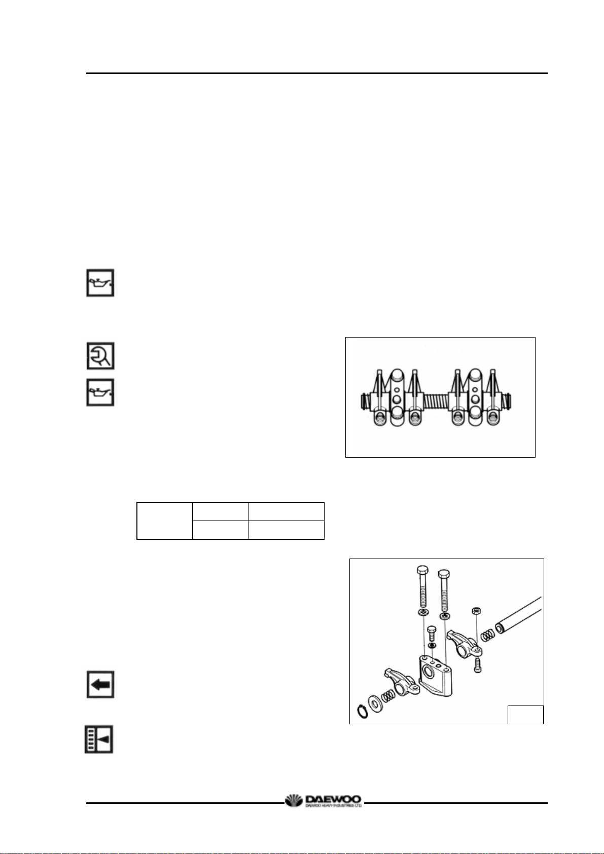
D1146/D1146TI/DE08TIS
MAINTENANCE MANUAL
(1) First stage : Coat the bolts with engine oil.
(2) Second stage : Tighten 1 ~2 threads with hands.
(3) Third stage : Tighten at about 6 kg.m with a wrench.
(4) Fourth stage : Tighten at rotating angle method 180° with a wrench.
(5) Fifth stage
: Finally, tighten at rotating angle method 150° with a torque
However, all bolts are tightened
simultaneously by above steps.
z Coat the push rod with engine oil and
insert it into the push rod hole.
3.3.28. Rocker arm assembly
z Apply lubricating oil to the rocker arm
bush and shaft, and assemble the
intermediate bracket with the rocker
arm (rocker arm assembly) on the
cylinder block using fixing bolts. In
tightening the bolts, it must be done at
the specified value using zigzag
method.
wrench .
G1088
M10x1.5 4.4 kg.m
Torque
M12x1.5 8.0 kg.m
z Semi-install valve clearance adjusting
bolts onto the rocker arm.
z Install the spring, rocker arm, bracket,
rocker arm, spring, washer, and snap
ring in the described sequence.
z Install the rocker arm and bracket in the
same direction.
G1056
z Adjust the valve clearance as
following guide.
89
Printed in Jan. 2001 PS-MMA0415-E1A
Page 94

D1146/D1146TI/DE08TIS
MAINTENANCE MANUAL
<Guide for valve clearance adjustment>
By turning the crankshaft, when the
intake and exhaust of #6 cylinder (the
fifth cylinder from the flywheel) overlap,
that is, when #1 cylinder’s piston come
at the compression top dead center (OT),
adjust the valve clearances by . mark
indicated.
After having turned the crankshaft by
360° and Intake & exhaust valves of #1
cylinder overlap, that is, when #6
cylinder is in the state of compression
TDC (OT), the clearance indicated by
mark is adjusted.
Flywheel
Intake Valve Exhaust Valve Cylinder No.
Cooling Fan
G1048
To adjust the clearance, loosen the lock
nuts of rocker arm adjusting screws and
push the feeler gauge of specified value
between a rocker arm and a valve stem
(to measure the clearance of the valve
and rocker arm contacting part) and
adjust the clearance with adjusting screw
respectively and then tighten with the
lock nut.
90
Printed in Jan. 2001 PS-MMA0415-E1A
Page 95

D1146/D1146TI/DE08TIS
MAINTENANCE MANUAL
As for the valve clearance, adjust it
when in cold.
Model
D1146
D1146TI
DE08TIS
Intake Valve Exhaust Valve
0.3 mm 0.3 mm
CAUTION :
(1) Crankshaft revolution is done by hands
without using a starting motor.
(2) Turn it to the direction of engine
rotation, but do not use the installing
bolts at the turn.
(3) The cylinder no. and the order of intake
and exhaust can be determined from
the crank shaft pulley.
z Adjust valve clearance with a feeler
gauge and tighten the fixing nuts to
specified torque.
Torque
3.3.29. Intake manifold
z Put in the new gasket between the
cylinder head and manifold, and
5.0 kg.m
Air heater
Valve clearance adjust
M1013
Intake manifold
assemble the intake manifold by
tightening the assembling bolts.
3.3.30. Exhaust manifold
91
Printed in Jan. 2001 PS-MMA0415-E1A
Page 96

D1146/D1146TI/DE08TIS
MAINTENANCE MANUAL
z Install the exhaust manifold gasket over
the stud bolts by aligning the gasket
with the exhaust port on the cylinder
head so that the face and back of the
gasket can be positioned correctly.
z Semi-assemble the exhaust manifold
and install the heat resisting plate.
z Assemble them by tightening the
assembling bolts. The tightening order
of bolts is from the middle to left and
right alternately.
CAUTION :
For upper and lower bolts differ in the
length, so use the correct bolts.
3.3.31. Turbocharger (D1146TI, DE08TIS)
z Fit a new gasket over the stud bolts of
the exhaust manifold before tightening
those turbocharger fixing nuts.
z Install the oil supply pipe and return
pipe.
z Tighten the clamps of rubber hose that
is connected air pipe to the intercooler.
3.3.32. Cooling water pipe
z Attach a new gasket on the cylinder
head.
z Install the cooling water pipe and
tightening the fixing bolt on it.
92
Printed in Jan. 2001 PS-MMA0415-E1A
Page 97

3.3.33 Idle pulley
z Assemble the air compressor
mounting bracket on the timing
gear case.
z Install the idle pulley on the air
compressor mounting bracket and
tightening the fixing bolt.
3.3.34 Air compressor & power steering pump
z Couple the power steering oil pump
to the air compressor with the driving
dog engaged.
D1146/D1146TI/DE08TIS
MAINTENANCE MANUAL
z Insert the O-ring coated with grease into
the oil outlet of the air compressor.
z Place the air compressor on the
mounting bracket carefully and tighten
the fixing bolts to the specified torque.
(Carefully damage the O-ring)
z Assemble the oil feed pipe.
3.3.35. Alternator
z Install the alternator mounting bracket
and supporter to the cylinder block, then
tighten the fixing bolts.
z Install the alternator with fixing bolts to
the mounting bracket.
3.3.36. Fuel filter
z Assemble the fuel filter with the intake
manifold.
z Assemble the fuel feed hose
according
93
Printed in Jan. 2001 PS-MMA0415-E1A
Page 98

to the direction of an arrow
impressed on the fuel filter head so
that fuel can be fed in the sequence of
FUEL FEED PUMP → FUEL FILTER
→ FUEL INJECTION PUMP.
3.3.37. Injection nozzle
D1146/D1146TI/DE08TIS
MAINTENANCE MANUAL
z Install a new seal ring in the nozzle hole
of the cylinder head.
z As aligning the ball of nozzle with
a
groove in the nozzle hole, Insert the
nozzle into the cylinder head and tighten
the nozzle.
Torque
7.0 kg.m
3.3.38. Fuel injection pipe
z Semi-assemble a nut at both ends of the
fuel injection pipe and tighten them up
one by one to specified torque.
G1104
Torque
3.0 kg.m
z Assemble the fuel return pipe on the
nozzle holder.
z Connect the injection pump lubricating
oil pipe with a hollow screw.
CAUTION :
Be sure not to damage the connection
part due to over-tightening the hollow
94
Printed in Jan. 2001 PS-MMA0415-E1A
Page 99

screw.
3.3.39. Cylinder head cover
z Attach a new gasket on the cylinder
head cover.
z Assemble the cylinder head cover to the
cylinder head by tightening the cap bolts
for fixing the cylinder head cover.
Torque 1.2 kg.m
z Assemble the breather and breather
hose.
z Fit the oil filler cap on the cylinder head
D1146/D1146TI/DE08TIS
MAINTENANCE MANUAL
cover.
3.3.40. Cooling fan
z Install the flange to the water pump
pulley, then assemble the cooling fan
to the pulley by tightening the fixing
bolts.
Torque
3.3.41. Belt
z Install the V-belt on the crank pulley,
alternator pulley and water pump
pulley.
z Adjust the V-belt tension using the
4.4 kg.m
G1086
10-15mm
Press here
tension adjusting support.
3.3.42. Oil level gauge
z Apply sealant (Locktite #262) to the
95
Water pump
pulley
G1105
Alternator
pulley
Crank pulley
Printed in Jan. 2001 PS-MMA0415-E1A
V-belt
Page 100

bottom side of the guide tube.
z Then assemble the guide tube and oil
level gauge on the oil pan.
3.3.43. Others
z Assemble by connecting the other oil and
D1146/D1146TI/DE08TIS
MAINTENANCE MANUAL
fuel hoses.
96
Printed in Jan. 2001 PS-MMA0415-E1A
 Loading...