

Page 1
CP830F Service Manual
-13-
3 ALIGNMENT INSTRUCTIONS
3.1MICROCONTROLLER CONFIGURATION : SERVICE MODE
To switch the TV set into service mode please see instruction below.
1 - Select PR. number 91
2 - Adjust sharpness to minimum and exit all menus.
3 - Within 2 seconds press the key sequence : RED - GREEN - menu
The software version is displayed beside the word Service, e.g.
SERVICE V1.00 .
To exit SERVICE menu press menu key or Std By key.
3.2SERVICE MODE NAVIGATION
Pr Up/Down remote keys : cycle through the service items available.
Vol -/+ remote keys : Dec./Increment the values within range - Cycle trough option bits.
OK key : Toggle bits in option byte
Order Item Default setting
1 HOR CEN
2 RED GAIN
3 GRN GAIN
4 BLUE GAIN
5 RED BIAS
6 GRN BIAS
7 AGC LEVEL
8 G2 - SCREEN
9AFT
10 OPTION1
11 OPTION2
12 PARABOLA
13 HOR WIDTH
14 CORNER T
15 CORNER B
16 HOR. PARAL
17 V. LINEAR
18 EW TRAPEZ
19 S CORRECT
20 VERT CENT
21 VERT SIZE
3.3 MICROCONTROLLER CONFIGURATION : OPTION BITS
There are two option bytes available (16 bits in all). These option bits are available from Service
mode. First find the OPTION1 or OPTION2 control, and then use the Volume PLUS/MINUS
buttons on the remote control keypad to locate the bits, and OK key to toggle them. The table
below shows the two option bytes available;
Page 2

CP830F Service Manual
-12-
2 SAFETY INSTRUCTION
WARNING: Only competent service personnel may carry out work involving the testing or repair
of this equipment.
X-RAY RADIATION PRECAUTION
1. Excessive high voltage can produce potentially hazardous X-RAY RADIATION. To avoid
such hazards, the high voltage must not exceed the specified limit. The nominal value of the
high
voltage of this receiver is 25-26 KV (20
-21 ) or 26 KV (25 - 28 ) at max beam current. The
high
voltage must not, under any circumstances, exceed 27.5 KV (20
), 29KV (21 ), 29.5 KV (25 )
or
30 KV (28
). Each time a receiver requires servicing, the high voltage should be checked. It is
important to use an accurate and reliable high voltage meter.
2. The only source of X-RAY Radiation in this TV receiver is the picture tube. For continued
X-RAY RADIATION protection, the replacement tube must be exactly the same type tube as
specified in the parts list.
SAFETY PRECAUTION
Potentials of high voltage are present when this receiver is operating. Operation of the receiver
outside the cabinet or with the back board removed involves a shock hazard from the receiver.
Servicing should not be attempted by anyone who is not thoroughly familiar with the
precautions
necessary when working on high voltage equipment.
Discharge the high potential of the picture tube before handling the tube. The picture tube is
highly evacuated and if broken, glass fragments will be violently expelled.
If any Fuse in this TV receiver is blown, replace it with the FUSE specified in the Replacement
Parts List.
When replacing a high wattage resistor (metal oxide film resistor) in the circuit board, keep the
resistor 10 mm away from circuit board.
Keep wires away from high voltage or high temperature components.
This receiver must operate under AC 230 volts, 5O Hz. NEVER connect to a DC supply or any
other voltage or frequency.
PRODUCT SAFETY NOTICE
Many electrical and mechanical parts in this equipment have special safety-related
characteristics. These characteristics are often passed unnoticed by a visual inspection and the
X-RAY RADIATION protection afforded by them cannot necessarily be obtained by using
replacement components rated for higher voltage, wattage, etc. Replacement parts which have
these special safety characteristics are identified in this manual and its supplements, electrical
components having such features are identified by designated symbol on the parts list. Before
replacing any of these components, read the parts list in this manual carefully. The use of
substitutes replacement parts which do not have the same safety characteristics as specified in
the parts list may create X-RAY Radiation.
Page 3

CP830F Service Manual
-14-
3.3.1 OPTION 1
B7 B6 B5 B4 B3 B2 B1 B0
TOP FASTEXT TUBE Headphone Dolby SVHS Tuner options
1 text (FLOF) 4:3 Volume/Balance Virtual 3 00 = Philips
OFF OFF control OFF OFF disable 01 = not used
TOP FASTEXT TUBE Headphone Dolby SVHS 10 = ALPS
0 text ON (FLOF) 16:9 Volume/Balance Virtual 3 11 = PARTSNIC
ON control ON ON enable (DW)
3.3.2 OPTION 2
B7 B6 B5 B4 B3 B2 B1 B0
1 Fixed to ‘0’ JVC remote control AVL control OFF PICTURE TILT ON Program list enabled
See table below.
0 Daewoo Remote control AVL control ON PICTURE TILT OFF Program list disabled
Beam Current
Tube (mA) B2 B1 B0
Nominal Max
0.95 1.10 0 0 0
1.00 1.15 0 0 1
4/3 - Super Flat, 16/9 – Super Flat 1.05 1.20 0 1 0
1.10 1.25 0 1 1
1.20 1.35 1 0 0
1.25 1.40 1 0 1
4/3 - Real Flat, 16/9 – Real Flat 1.30 1.45 1 1 0
1.35 1.50 1 1 1
All values modified are immediately memorised in eeprom.
3.4 TV SET ALIGNMENT
3.4.1 LOCAL OSCILLATOR ALIGNMENT
Tune a colour bar pattern. The frequency of the signal carrier must be accurate ( Max +/- 10KHz deviation from the
nominal channel frequency).
Find
AFT item in service mode.
Adjust the coil L150 to bring the cursor to central position : 32.
3.4.2 G2 ALIGNMENT
- Tune a colour bar pattern.
- Find the
G2 - SCREEN item in service mode.
- Adjust screen volume ( on FBT ) to bring the cursor to central position : 32.
Page 4

CP830F Service Manual
-15-
3.4.3 WHITE BALANCE
- Select a dark picture and adjust RED BIAS and GRN BIAS to the desired colour temperature.
- Select a bright picture and adjust RED, GRN and BLUE GAIN to the desired colour temperature.
3.4.4 FOCUS
Adjust the Focus volume ( on FBT ) to have the best resolution on screen.
3.4.5 VERTICAL GEOMETRY
Adjust V. LINEAR (linearity), S CORRECT (S. Correction), VERT SIZE (Vertical amplitude), VERT CENT (vertical
centring) to compensate for vertical distortion.
3.4.6 HORIZONTAL PICTURE CENTRING
Adjust HOR CEN (Horizontal centre) to have the picture in the centre of the screen.
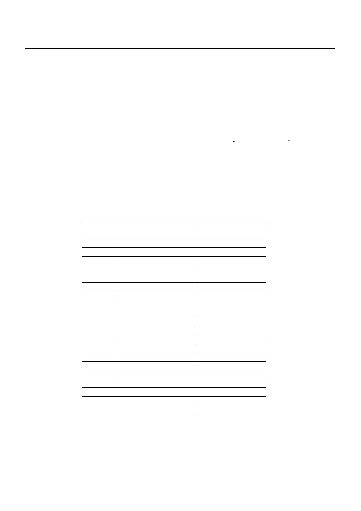
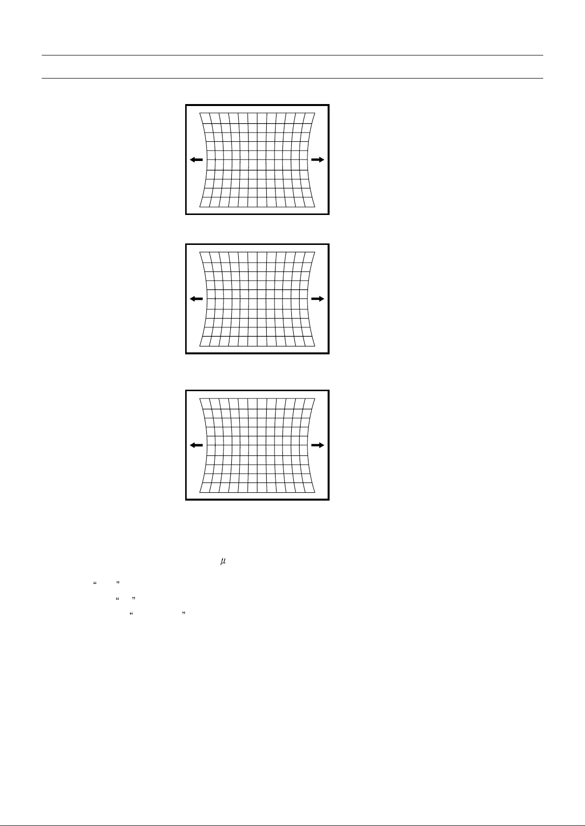
3.4.7 EAST / WEST CORRECTION
Adjust the PARABOLA, HOR WIDTH, CORNER, HOR PARAL, EW TRAPEZ, to compensate for
geometrical distortion.
HOR PARAL
HOR WIDTH
adjust for 93% overscan.
Page 5
CP830F Service Manual
-16-
PARABOLA
CORNER B & CORNER T
EW TRAPEZ
3.4.8 AGC
- Make sure option bits are correct for the tuner fitted on the chassis (See above how to change option bits).
- Adjust the antenna signal level at 64 dB
V± 2
- Tune a colour bar pattern.
- Find the
AGC item in service mode.
- Press the key
OK on the remote keypad and wait until AGC level stabilise to the optimum value.
- Alternatively, use
Vol Up/Dwn keys to adjust manually to the desired Tuner Take Over Point (TOP).
 Loading...