

Page 1

1
TABLE OF CONTENTS
1. PRECAUTION...................................................................................................................................2
2. GENERAL SPECIFICATIONS.........................................................................................................3
3. NAMES OF MAJOR COMPONENTS.............................................................................................4
4. FUNCTION OF MAIN COMPONENTS........................................................................................... 5
5. GENERAL INFORMATIONS............................................................................................................6
6. CARE AND MAINTENANCE...........................................................................................................7
7. TROUBLE SHOO TING GUIDE...................................................................................................8~9
8. HOW TO DISASSEMBLE..............................................................................................................10
9. WIRING DIAGRAM.........................................................................................................................11
10. REFRIGERANT CYCLE...............................................................................................................12
11. EXPLODED DIAGRAM AND PARTS LIST................................................................................13
Page 2

2
1. PRECA UTION
Please observe the following instructions.
1. Turn off unit.
Make sure the unit is OFF and the AC cord is unplugged before repairing or servicing.
2. In case of checking the circuit una v oidab l y while the unit is connected with po wer sour ce, be careful
not to connect with the part of electric charge.
You may cause electric shock.
3. Use of proper part if you need to replace the part, be sure to use genuine part of servicing model.
Do not repair or replace the electric contact part.
Consumer must not repair the unit, because it is dangerous.
4. Use of proper tool.
You must use the proper tool to repair the unit, and use the measuring appliance adjusted accurately.
5. Damage of electric wire and power cord when servicing.
Check electric wire and a surely replace a damage electric wire and a damage power cord.
6. Never use connecting the middle of wire, after cutting the middle of wire.
It may cause a fire and trouble.
7. Checking the insulation resistance.
After you complete the assembly of unit, surely check the insulation resistance.
Confirm that the insulation resistance of the power line and the ground terminal is over 30MΩ by measuring insulation
resistance.
8. Checking the ground.
After checking the ground, servicing it completely.
9. Checking the installation.
After checking the installation, servicing it completely.
10. Care children.
When servicing, do not make the children approach the air-conditioner.
Page 3
3
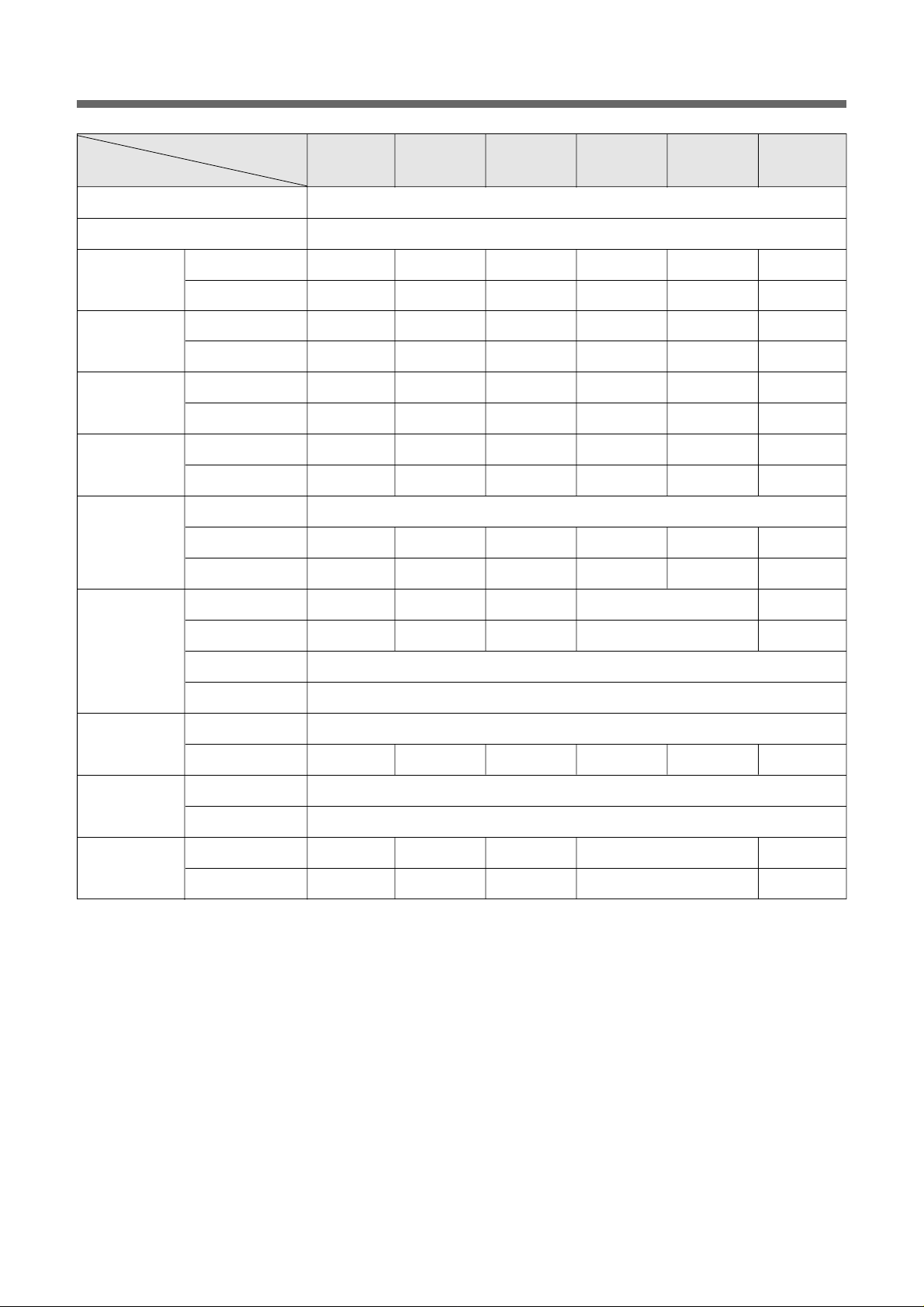
2. GENERAL SPECIFICATIONS
ITEM
MODEL
DWB-050C DWB-070C DWB-091C DWB-070C-D DWB-070C-M DWB-091C-D
Function Cooling Only
Power source AC 220 - 240V / 50Hz
Btu/h 5,100 7,300 8,600 7,200 7,150 8,600
Kcal/h 1,285 1,840 2,170 1,815 1,800 2,167
Btu/Wh 8.60 9.67 9.30 9.86 9.7 9.94
Kcal/Wh 2.17 2.44 2.35 2.48 2.44 2.51
Pts/h 0.99 2.02 2.49 2.43 2.13 2.66
g/h 450 910 1,130 1,105 970 1,210
Power Input (W) 595 755 925 730 735 865
Running Current (A) 2.6 3.2 4.1 3.1 3.3 3.6
Type ROTARY
Model QA096PK11B QB134PL12A QK164PN12C RBB070A001 KH127VFHC RBB090A001
Capacitor 25µF/400VAC 25µF/400VAC 30µF/400VAC 25µF/400VAC 17µF/400VAC 30µF/400VAC
Model A9525TS401 A9525TS401 A9525TS402 A9525TS401 A9525TS402
Capacitor 2µF / 400VAC 2µF/400VAC 3µF/400VAC 2µF/400VAC 3µF/400VAC
Indoor-Fan Blower-Fan
Outdoor-Fan Propeller-Fan
Control Capillary
Charge Amount (g) 280g 380g 480g 430g 390g 520g
Unit(W x H x D)
Packing(W x H x D)
Net Weight (Kg) 23.7 28.5 29.5 28.5 29.5
Gross Weight (Kg) 25 30 31 30 31
Cooling
Capacity
Energy
Efficiency
Ratio
Dehumidification
Electrical Data
Compressor
Fan Motor
Refrigerant (R-22)
Dimensions
Weight
470(W )x 358(H) x 480(D) mm
540(W )x 455(H) x 550(D) mm
Page 4
4
3.NAMES OF MAJOR COMPONENTS
NO PART NAME
1 CABINET
2 BLADE VERTICAL
3 COOL AIR DISCHARGE
4 GRILL FRONT
5 KNOB SELECTOR
6 KNOB THERMOSTAT
NO PART NAME
7 AIR INTAKE
8 AIR FILTER
9 CONTROL PANEL
10 PLATE WINDOW TOP
11 FRAME WINDOW KIT
12 SHUTTER WINDOW
2
3
8
5
6
1
4
7
0
q
w
9
2
3
8
5
6
9
1
4
7
❊ Window kits are optional.
(Item No. 10, 11, 12)
Page 5
5
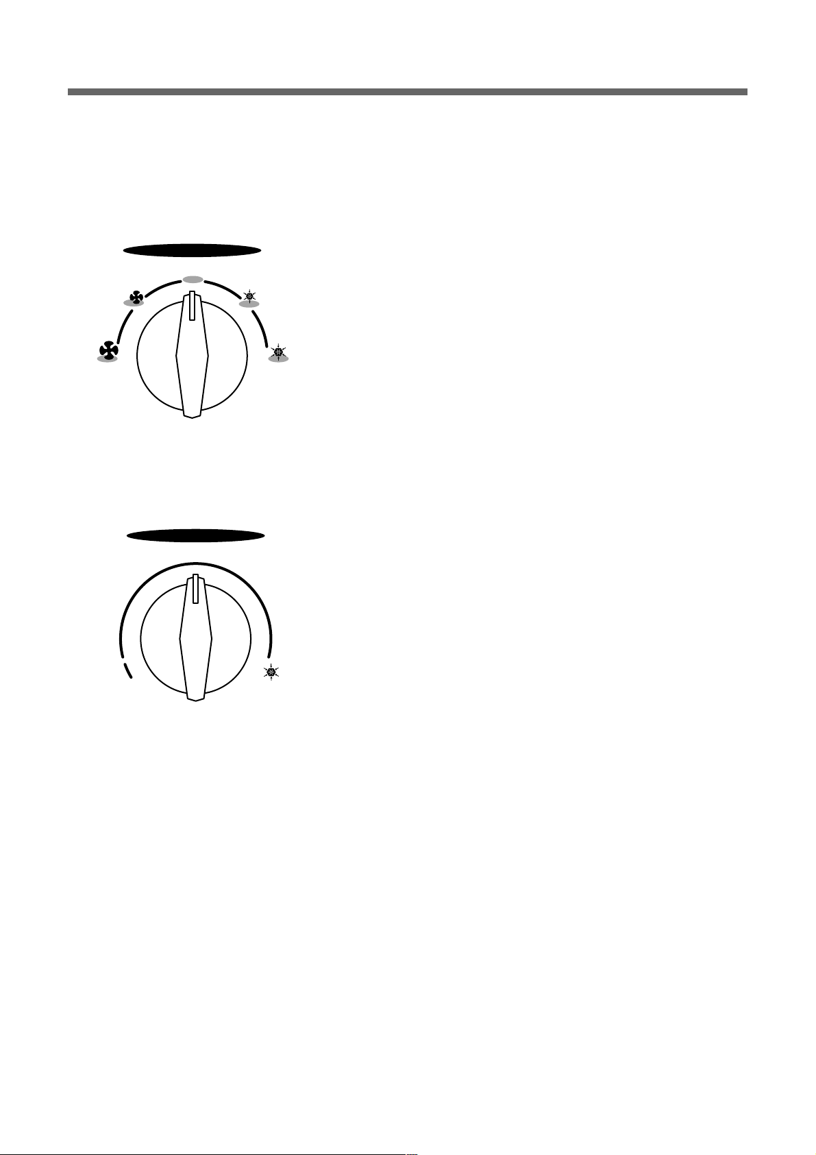
4. FUNCTION OF MAIN COMPONENTS
1. ROTARY SWITCH (SELECT OR)
Please refer to the part of selector in the chapter 9 (Wiring Diagram).
The rotary switch (selector) controls the fan motor’s rotation speed, and has five positions.
The function of the five position is as follow.
• OFF: This position stops all operations of the air conditioner.
• HIGH COOL: This position provides the maximum air flow for rapid
cooling, dehumidifying and dust removing operations.
(Use this position on sultry summer days.)
• LOW COOL: This position provides the minimum air flow for quiet
cooling, dehumidifying operations.
(Use this position on suitable for night-time.)
• HIGH FAN: This position provides the maximum air fiow alone fan
operation without cooling operation.
• LOW FAN: This position provides the minimum air flow air flow alone
fan operation without cooling operation.
2. THERMOSTA T (TEMPERATURE CONTROL)
• The Thermostat automatically starts and stops operation in order to keep
the room temperature at a proper level, and this results in efficient use of
power and economical cooling.
• Turn clockwise for a cooler room temperature.
• Turn counter-clockwise for a warmer room temperature.
3. MOT OR
The motor is used to rotate the indoor and outdoor fan so that the room air can be recirculated.
4. F AN
• BLOWER FAN: The Blower draws hot air from the room through the Evaporator and then discharges it back into the
cool air. It circulates the room air.
• PROPELLER FAN: The propeller draws outdoor air through louvering and cools Condenser, and then blows the hot
air out.
5. CAPACIT OR
The Capacitor enlarges the difference of phase between main coil and sub coil so that the Compressor and Fan Motor
starts well.
6. ACCUMULATOR
The Accumulator blocks the unflow of liquid refrigerant and impurities into the Compressor.
SELECTOR
HIGH
COOL
HIGH
FAN
LOW
COOL
LOW
FAN
OFF
THERMOSTAT
COOLER
Page 6

6
5. GENERAL INFORMATIONS
1. CHANGING AIR FLOW DIRECTION
Air flow deflectors divert air from center flow to left or right.
Adjust deflectors for desired air flow pattern.
2. AIR FLOW AR OUND UNIT
Check in door grill and outdoor louvers for air flow obstructions. Do not block air flow to and from unit. The outdoor coil
should be checked and periodically cleaned for debris that may collect and block unit air flow. If air flow is obstructed
or deflected back into unit, the compressor may cycle on and off rapidly, causing early compressor failure.
3. Electrical Grounding Instructions.
This appliance is equipped with a three-prong(grounding) plug for protection against possible shock hazards. If a twoprong wall receptacle is encountered, the customer is required to contact a qualified electrician and have the twoprong wall receptacle replaced with a properly grounded three-prong wall receptacle in accordance with the National
Electrical Code.
4. USE OF EXTENSION CORDS
Because of potential safety hazards under certain conditions we strongly recommend against the use of an extension
cord. However, if you still elect to use an extension cord, it is absolutely necessary that it is earthed and the marked
rating of the extension cord should be 250V 10A or more.
5. DRAIN HOLE AND W ATER DRIPPING OUTSIDE
Locate drain hole at the rear of unit. Water in base pan is picked up by the fan blade and thrown onto the warm
outdoor coil where it evaporates. The air conditioner must be installed level or tited or slightly to the outside for proper
water disposal. On exceptionally hot and humid days the air conditioner may permit excess water to pass thru rear
drain hole or overflow. This should be considered normal.
Page 7

7
6. CARE AND MAINTENANCE
1. AIR FILTER
Clean the air filter, which removes dust inside the room.
It should be washed at least once every week during operation.
1. Remove the Air Filter from the front grill by pulling up.
2. Clean Air Filter with a vacuum cleaner or lukewarm, soapy water.
3. Shake it when clean to remove moisture completely. Replace it.
2. CLEANING THE AIR CONDITIONER
1. At least once a year, remove cabinet and thoroughly clean air conditioner. Have the unit inspected by an authorized
servicer to ensure unit is functioning properly.
2. Wash air conditioner with lukewarm, soapy water as needed. Rinse and dry thoroughly.
3. If using concentrated liquid detergent, dilute in warm water first.
4. Front grill may be wiped off with a cloth dampened in a mild detergent solution.
5. Cabinet may be washed with mild soap or detergent and lukewarm water, then polished with liquid wax for
appliances.
6. Condenser and Evaporator coils should be cleaned at the beginning of each cooling season. Use a soft brush or
vacuum cleaner to clean them, making sure that the Condenser and Evaporator coils are not damaged.
7. Do not use abrasive cleaners. These items scratch, crack and discolor surfaces.
Page 8
8
7. TROUBLE SHOO TING GUIDE
TROUBLE SITUATION ANALYSIS CAUSE REMED Y
Fan motor and
compressor do not
run
Switch is in “cool”
position but the
compressor does not
run
1. Power failure
2. Power is supplied,
but the equipment
does not run
1. Not operating at all
2. Compressor
3. Frequent start and
stop
1) Power plug
2) Circuit breaker
1) receptacle
2) Operation switch
3) Cord or lead wire to
the switch
1) Compressor
2) Thermostat
3) Selector switch
4) O.L.P
5) Capacitor
1) Electricity
2) Room temperature
and outside
temperature
3) Compressor
4) O.L.P
5) Capacitor
1) Thermostat
2) Capacitor
3) O.L.P
1) Power failure
2) Circuit breaker is tripped
3) Power plug is not contacting
• Disconnection
• Mechanical failure of switch
1) Disconnection
2) Malfunction of contact
• Disconnection or burned-out
1) Failure
2) Malfunction
3) Knob is not set to the proper
setting
• Failure of malfunction of proper
setting
1) Disconnection
2) Malfunction of contact
• Lack of capacity
• Disconnection
1) The voltage exceeded allowed
range
2) Capacity of wire is not
sufficient
• Extremely high
• Burned-out
• Malfunction
• Lack of capacity
• Malfunction
• Lack of capacity
• Malfunction
• Consult your electric company
• In case of a breaker, turn it on
and off a few times
• Replace the power plug
• Repair or replace the
receptacle
• Replace the cord or lead wire
• Replace the compressor or
connection wire
• Replace
• Repair or replace
• Turn knob for cooler setting
• Repair or replace the swtting
• Repair
• Repair or replace
• Replace
• Repair
• Consult your electric company
• Check the capacity of wire
• Ventilate well and remove the
heat source
• Replace
• Replace
• Replace
• Replace
• Replace
• Replace
Page 9

9
TROUBLE SITUATION ANALYSIS CAUSE REMED Y
The compressor runs
but the motor doesn’t
run
Both fan motor and
compressor are
running but cooling is
bad
Vibration & Noise
Water leakage into
room
Electric shock
(Leakage of current)
Not cooling at all
Insufficient cooling
1) Fan
2) Fan motor
3) Capacitor
4) Fan motor circuit
Refrigerant system
1) Refrigerant system
2) Filter
3) Heat exchanger of
condenser
1) Installation place
2) Fan
3) Fixing screws
4) Electric
components
• Installation condition
• Insulation of
components
• Blocked by others
• Disconnection or burned-out
electric cord
• Failure malfunction of contact
• Disconnection of malfunction of
contact
1) Refrigerant system is choked
2) Compressor failure
3) Leakage of refrigerant gas
1) Refrigerant system is choked
2) Compressor failure
3) Leakage of refrigerant gas
4) Refrigerant charge is too high
• Clogged up with dust
1) Fin is cogged up with dust
2) The ventilation is not good
3) The unit is exposed to the
sunlight
4) Other heat source is added in
the room
• Installation of the unit is
imperfectly done
1) Fan is contacted with
obstacles
2) Fixing bolt
• Have a screw loose
• Electrical noise
• The front is lower than rear side
1)Insulation defect of wiring and
lead wire
2) Leakgae of current due to the
dew or rust
• Repair
• Replace the fan motor
• Replace
• Check the circuit
• Repair
• Repair
• Recharge refrigerant gas
• Check and repair refrigerant
system
• Replace
• Check a part of Leakage and
repair
• Repair and recharge
• Clean the air fiter
• Clean the unit
• Shade the unit from the
sunlight
• Remove the added heat source
• Install the unit perfectly
• Remove obstacles
• Tighten the bolt
• Tighten the screw
• Exchange the components
• Make rear side of the unit lower
than the front
• Check the unit’s Leakage of
current.
• Replace the defective parts or
components
Page 10

10
8. HO W T O DISASSEMBLE
1 Before service of 1. Stop the unit, remove the power cord from the receptacles.
any part. 2. Move the unit to the safe location for the suitable work.
2 Ass’y Fan Motor 1. Remove Front Grill
- Fan Motor - Remove Filter Pre.
- Propeller Fan - Remove screw(1 point) in Front Grill.
- Blower Fan 2. Remove Cabinet from the unit.
- Remove screws (8 point) from the unit’s sides.
3. Remove Scroll upper.
4. Remove Plate Scroll
- Remove screws (3 point) from Plate Scroll’s sides.
5. Remove Ass’y Control Box
- Remove screws (3 point).
- Remove wires in the each components.
6. Remove wires in the Panel Housing.
7. Remove screws (7 point) from Ass’y Fan Motor’s sides.
- Ass’y Fan Motor is assembly of Fan Motor, Propeller and Blower Fan, Orifice
and Panel Housing.
8. Lift the Ass’y Fan Motor from the unit.
9. Remove hex-nut (2 point) from the shaft of Fan Motor.
10. Remove Propeller Fan from the shaft of Fan Motor.
11. Remove Blower Fan from the shaft of Fan Motor.
12. Remove Fan Motor from Panel Housing.
- Remove screws (4 point).
3 Ass’y Control Box 1. Same as the procedure 1 to 5 in the Item 2.
-
Rotary Switch (selector)
- Thermostat
- Capacitor
- Power Cord
4 O.L.P 1. Same as the procedure 1 to 2 in the Item 2.
2. Remove Terminal Cover from Compressor.
- Remove hex-nut (1 point).
Please refer to the chapter 11 (Exploded diagram and parts list).
Page 11

11
9. WIRING DIA GRAM
COMP
F.M
R
C
O.L.P
BR
RD
OR
OR
GY
GN
(Lo)
(Hi)
WH
CAPACITOR
BR
YW
BL
HiFAN
LOFAN
LOCOOL
HiCOOL
OFF
SELECTOR SWITCH
BK AC115V/60Hz
21
4
87
THERMOSTAT
F
S
C
H
(BL) (BR)
Page 12

12
Condenser
Propeller fan
Capillary tube
Compressor
Accumulator
Blower fan
Evaporator
M MOTOR
10. REFRIGERANT CYCLE
Page 13

13
11. EXPLODED DIA GRAM AND PAR TS LIST.
■ DWB-050C PARTS LIST
NO. CODE COMPONENTS Q’TY SPECIFICATION REMARK
1 3100300700 PAN BASE 1 PP+T30% OR PP+CACL3(40%)
2 3106002400 COMP BOLT 3 M8XP1.25XL57
3 3106600401 SCROLL LOWER 1 EPS
4 2221040001 SEALING PUTTY 0.01 GRAY(PGE000901)JOINT SEALER
5 3100086500 COMPRESSOR 1 QA096PK11B, 220V-50HZ
6 3RC8104AE0 GROMMET 3 EPDM 45
7 7400208411 WASHER PLAIN 3 M8(ID8.4XOD22XT1.6)
8 7392801211 NUT LOCK 3 M8XP1.25(RIGHT SCREW)
9 3100072700 ASS'Y CONDENSOR 1 1RX1C, DWC-050
10 7112401611 SCREW TAPPING 2 T1 TRS 4X16 MFZN
11 3104430700 PIPE COND IN 1 C1220T-OL. OD7.94XT0.7
12 3100073210 ASS'Y PIPE CAPILLARY 1
13 3104431610 PIPE CAPILLARY 1
14 3100077400 ASS'Y EVAPORATOR 1 1RX1C
15 3104430900 ASS'Y PIPE EVA OUT 1 DWC-050C
16 3104430600 ASS'Y PIPE EVA IN 1 DWC-050C
17 3100072800 ASS'Y PIPE SUCTION 1 DWC-050C
18 7112401611 SCREW TAPPING 2 T1 TRS 4X16 MFZN
19 3108003300 MOTER FAN 1 A9525TS401,220V-50HZ
20 3104201500 PANEL HOUSING 1 SGCC Z-27
21 3101402400 COVER ORIFICE 1 PP
22 7S432X4081 SCREW TAPTITE 4 TT3 TRS 4X8 SE MFZN
23 7122401211 SCREW TAPPING 3 T2S TRS 4X12 MFZN
24 3101801820 FAN BLOWER 1 ABS Ø8
25 3106000600 WASHER PLAIN 1 M6(ID6.4XOD19.8XT1.6)
26 3106000500 NUT HEX(R) 1 M6(RIGHT SCREW)
27 3101801910 FAN PROPELLER 1 ABS+GF20%Ø8
28 3106000600 WASHER PLAIN 1 M6(ID6.4XOD19.8XT1.6)
29 3106000400 NUT HEX(L) 1 M6(LEFT SCREW)
30 3100700600 BUSHING GUIDE 1 NBR(HS 60˚ ±5˚)
31 3103800400 LOCK TWIST STANDOFF 3 DASTL-3NA
32 3100700900 BUSHING HOUSING 1 NBR(HS 60˚ ±5˚)
33 3100504000 BOX CONTROL 1 SGCC T0.8X332X270P REGULLAR-SP
34 5S10503100 S/W ROTARY 1 DAESUNG SRB 315-4-7D,5-STEP
35 7001400611 SCREW MACHINE 4 M/C PAN 4X6 MFZN
36 5SM0101820 THERMOSTAT AS 1 PFA 602D-06C
37 3109502100 CAPACITOR 1 2/25µF, 370/400VAC
38 3101201600 CLAMP CAPACITOR 1 SGCC T0.8X113XCOIL REGULLAR-SP
39 7S432X4081 SCREW TAPTITE 1 TT3 TRS SE 4X8 MFZN
40 3101396120 POWER CORD 1 SJT AWG #16X3(KDK)
Page 14

14
NO. CODE COMPONENTS Q’TY SPECIFICATION REMARK
41 7S432X4081 SCREW TAPTITE 1 TT3 TRS SE 4X8 MFZN
42 7S432X4081 SCREW TAPTITE 1 TT3 TRS SE 4X8 MFZN
43 3103521000 LABEL CIRCUIT 1 P.E T0.05
44 3100701100 BUSHING COVER 0.4 DACB-008(L=300)
45 3102702100 HARNESS ROTARY S/W 1 AWG-16UL(BR)
46 3108502900 SEAL CONTROL BOX 1 F-US,258X264XT5(D/G)
47 3102702000 HARNESS COMP ASSY 1 AWG-16,UL(BR/RD/OR)
48 - OVER LOAD PROTECT 1
49 - GASKET 1 SILICON
50 - COVER TERMINAL 1 PC
51 - NUT 1 HEXAGON FLANGE
52 3108502700 SEAL EVA TOP 1 F-US,350X40XT5
53 3104504800 PLATE SCROLL 1 PP+T30
54 3108503800 SEAL SCROLL 1 F-US,115X60XT5(D/G)
55 7122401211 SCREW TAPPING 3 T2S TRS 4X12 MFZN
56 3106600300 SCROLL UPPER 1 EPS
57 3108502810 SEAL COND TOP 1 F-US,400X15XT10
58 3100077700 CABINET ASSY 1 DWC-050C PAINT
59 3100603400 BRACKET CABINET 1 DW-070
60 3104505600 PLATE WINDOW TOP 1 SECC T1.2X82.5X466.5(GY-258D) PAINT
61 7112401211 SCREW TAPTITE 3 T2S TRS 4X12 MFZN
62 3108503100 SEAL CABINET TOP 1 F-US+F-PE(470X155XT10/2)
63 3108503200 SEAL CABINET SIDE(L) 1 F-US(310X90XT5)
64 3108503400 SEAL CABINET SIDE(R) 1 F-US(310X155XT5)
65 3108503000 SEAL CABINET FLANGE 1 F-US(540X10XT5)
66 7112401211 SCREW TAPPING 6 T1 TRS M4X12 POLY/WAS MFNI
67 3102403600 GRILLE FRONT 1 HIPS
68 3108503700 SEAL FRONT(C) 2 F-US(80X20XT30)
69 3108503500 SEAL FRONT(A) 1 F-US(600X20XT10)
70 3108503600 SEAL FRONT(B) 1 F-US(420X20XT10)
71 3106501100 BLADE VERTICAL 2 PP
72 3101601600 DECO FRONT 1 PC T0.4
73 7112400811 SCREW TAPPING 1 T1 TRS 4X8 MFZN
74 3100074900 ASS'Y KNOB 2 DWC-050C
75 3101902800 FILTER PRE 1 HIPS+MESH#32
76 3107000900 CLIP THERMO 1 ABS
Page 15

NO CODE COMPONENTS Q'TY SPECIFICATION REMARK
1 3100300700 PAN BASE 1 PP+T30% OR PP+CACL3(40%)
2 3106002400 COMP BOLT 3 M8XP1.25XL57
3 3106600400 SCROLL LOWER 1 EPS 070C,091C
3106600401 SCROLL LOWER 1 EPS 070C-D,070C-M,091C-D
4 2221040001 SEALING PUTTY 0.05 GRAY(PGE000901)JOINT SEALER
5 3100049100 COMPRESSOR 1 QB134PL12A, 220V-50HZ 070C
3100049400 COMPRESSOR 1 QB164PN12C, 220V-50HZ 091C
3100075400 COMPRESSOR 1 RBB070A001, 220V-50HZ 070C-D
3117100700 COMPRESSOR 1 KH127VFHC, 220V-50HZ 070C-M
3100075500 COMPRESSOR 1 RBB090A001, 220V-50HZ 091C-D
6 – GROMMET 3 EPDM 45 070C,091C
3RC8104AE0 GROMMET 3 EPDM 45 070C-D,070C-M,091C-D
7 7400208411 WASHER PLAIN 3 M8(ID8.4XOD22XT1.6)
8 7392801211 NUT LOCK 3 M8XP1.25(RIGHT SCREW)
9 3100029400 ASS'Y CONDENSOR 1 2RX1CX17S 070C,070C-D,070C-M
3100049700 ASS'Y CONDENSOR 1 3RX2CX17S 091C,091C-D
10 7112401611 SCREW TAPPING 2 T1 TRS 4X16 MFZN
11 3104414400 PIPE COND IN 1 C1220T-OL. OD7.94XT0.7 070C
3104414410 PIPE COND IN 1 C1220T-OL. OD7.94XT0.7 070C-D
3114401100 PIPE COND IN 1 C1220T-OL. OD7.94XT0.7 070C-M
3100049800 PIPE COND IN 1 C1220T-OL. OD7.94XT0.7 091C
3100075100 PIPE COND IN 1 C1220T-OL. OD7.94XT0.7 091C-D
12 3100034310 ASS'Y PIPE CAPILLARY 1 Ø1.6X1100 070C
3100034340 ASS'Y PIPE CAPILLARY 1 Ø1.2X600 070C-D
3110012600 ASS'Y PIPE CAPILLARY 1 Ø1.4X800 070C-M
3100034330 ASS'Y PIPE CAPILLARY 2 Ø1.0X400 091C,091C-D
13 3104414650 PIPE CAPILLARY 1 Ø1.6X1100 070C
3104432900 PIPE CAPILLARY 1 Ø1.2X600 070C-D
3114406100 PIPE CAPILLARY 1 Ø1.4X800 070C-M
3104414610 PIPE CAPILLARY(1) 1 Ø1.0X400 091C,091C-D
3104414620 PIPE CAPILLARY(2) 1 Ø1.0X400 091C,091C-D
14 3100029300 ASS'Y EVAPORATOR 1 2RX2CX12S 070C,070C-D,070C-M
3100049600 ASS'Y EVAPORATOR 1 3RX2CX13S 091C,091C-D
15 3100034500 ASS'Y PIPE EVA OUT 1 DWC-070C 070C,070C-D,070C-M
3100050000 ASS'Y PIPE EVA OUT 1 DWC-091C 091C,091C-D
16 3100034400 ASS'Y PIPE EVA IN 1 DWC-070C 070C
3100034410 ASS'Y PIPE EVA IN 1 070C-D,070C-M
3104414630 PIPE EVA IN 1 1 091C,091C-D
3104414640 PIPE EVA IN 2 1 091C,091C-D
17 3100034600 ASS'Y PIPE SUCTION 1 DWC-070C 070C
3100075000 ASS'Y PIPE SUCTION 1 070C-D
3110002400 ASS'Y PIPE SUCTION 1 070C-M
3100050100 ASS'Y PIPE SUCTION 1 091C
3100075030 ASS'Y PIPE SUCTION 1 091C-D
18 7112401611 SCREW TAPPING 2 T1 TRS 4X16 MFZN
15
■ DWB-070C,D WB-091C,DWB-070C-D,D WB-070C-M,D WB-091C-D PARTS LIST
Page 16

16
NO CODE COMPONENTS Q'TY SPECIFICATION REMARK
19 3108003300 MOTOR FAN 1 A9525TS401,220V-50HZ 070C,070C-D,070C-M
3108003600 MOTOR FAN 1 A9525TS402,220V-50HZ 091C,091C-D
20 3104201500 PANEL HOUSING 1 SGCC Z-27
21 3101402400 COVER ORIFICE 1 PP
22 7S432X4081 SCREW TAPTITE 4 TT3 TRS 4X8 SE MFZN
23 7122401211 SCREW TAPPING 3 T2S TRS 4X12 MFZN
24 3101801820 FAN BLOWER 1 ABS Ø8
25 3106000600 WASHER PLAIN 1 M6(ID6.4XOD19.8XT1.6)
26 3106000500 NUT HEX(R) 1 M6(RIGHT SCREW)
27 3101801910 FAN PROPELLER 1 ABS+GF20%Ø8
28 3106000600 WASHER PLAIN 1 M6(ID6.4XOD19.8XT1.6)
29 3106000400 NUT HEX(L) 1 M6(LEFT SCREW)
30 3100700600 BUSHING GUIDE 1 NBR(HS 60° ±5°)
31 3103800400 LOCK TWIST STANDOFF 3 DASTL-3NA
32 3100700900 BUSHING HOUSING 1 NBR(HS 60°±5°)
33 3100504000 BOX CONTROL 1 SGCC T0.8X332X270P REGULLAR-SP
34 5S10503100 S/W ROTARY 1 DAESUNG SRB 315-4-7D,5-STEP
35 7001400611 SCREW MACHINE 4 M/C PAN 4X6 MFZN
36 5SM0101600 THERMOSTAT AS 1 PFA 602D-06B 070C,091C
5SM0101610 THERMOSTAT AS 1 PFA 602D-06B 070C-D,070C-M,091C-D
37 3109502100 CAPACITOR 1 2/25µF,400VAC 070C,070C-D
3116901000 CAPACITOR 1 2/17µF,400VAC 070C-M
3109506300 CAPACITOR 1 3/30µF,400VAC 091C,091C-D
38 3101201600 CLAMP CAPACITOR 1 SGCC T0.8X113XCOIL REGULLAR-SP
39 7S432X4081 SCREW TAPTITE 1 TT3 TRS SE 4X8 MFZN
40 3101396120 POWER CORD 1 SJT AWG #16X3(KDK)
41 7S432X4081 SCREW TAPTITE 1 TT3 TRS SE 4X8 MFZN
42 7S432X4081 SCREW TAPTITE 1 TT3 TRS SE 4X8 MFZN
43 3103524300 LABEL CIRCUIT 1 P.E T0.05 070C
3103524400 LABEL CIRCUIT 1 P.E T0.05 091C
3103520500 LABEL CIRCUIT 1 P.E T0.05 070C-D,070C-M
3103521400 LABEL CIRCUIT 1 P.E T0.05 091C-D
44 3100701100 BUSHING COVER 0.4 DACB-008(L=300)
45 3102702100 HARNESS ROTARY S/W 1 AWG-16UL(BR)
46 3108502900 SEAL CONTROL BOX 1 F-US,258X264XT5(D/G)
47 3102702000 HARNESS COMP ASSY 1 AWG-16,UL(BR/RD/OR)
48 – OVER LOAD PROTECT 1 MRA12012-12003 070C
– OVER LOAD PROTECT 1 MRA98776-12026 091C
3RC7908GE0 OVER LOAD PROTECT 1 070C-D
– OVER LOAD PROTECT 1 BF690-KB 070C-M
3RC7908HE0 OVER LOAD PROTECT 1 091C-D
49 – GASKET 1 SILICON 070C,070C-M,091C
3RC2304AE0 GASKET 1 SILICON 070C-D,091C-D
50 – COVER TERMINAL 1 PC 070C,070C-M,091C
3RC1405AE0 COVER TERMINAL 1 PC 070C-D,091C-D
Page 17

17
NO CODE COMPONENTS Q'TY SPECIFICATION REMARK
51 – NUT 1 HEXAGON FLANGE 070C,070C-M,091C
3RC8009AE0 NUT 1 HEXAGON FLANGE 070C-D,091C-D
52 3108502700 SEAL EVA TOP 1 F-US,350X40XT5
53 3104504800 PLATE SCROLL 1 PP+T30
54 3108503800 SEAL SCROLL 1 F-US,115X60XT5(D/G)
55 7122401211 SCREW TAPPING 3 T2S TRS 4X12 MFZN
56 3106600300 SCROLL UPPER 1 EPS
57 3108502800 SEAL COND TOP 1 F-US,400X15XT10
58 3100034900 CABINET ASSY 1 DW-070(STOP WELDING) PAINT
59 3100603400 BRACKET CABINET 1 DW-070
60 3104505600 PLATE WINDOW TOP 1 SECC T1.2X82.5X466.5(GY-258D) PAINT
61 7S432X4081 SCREW TAPTITE 3 T2S TRS 4X12 MFZN
62 3108503100 SEAL CABINET TOP 1 F-US+F-PE(470X155XT10/2)
63 3108503200 SEAL CABINET SIDE(L) 1 F-US(310X90XT5)
64 3108503400 SEAL CABINET SIDE(R) 1 F-US(310X155XT5)
65 3108503000 SEAL CABINET FLANGE 1 F-US(540X10XT5)
66 7112401211 SCREW TAPPING 6 T1 TRS M4X12 POLY/WAS MFNI
67 3102401900 GRILLE FRONT 1 ABS 070C,091C
3102403600 GRILLE FRONT 1 HIPS 070C-D,070C-M,091C-D
68 3108503700 SEAL FRONT(C) 2 F-US(80X20XT30)
69 3108503500 SEAL FRONT(A) 1 F-US(600X20XT10)
70 3108503600 SEAL FRONT(B) 1 F-US(420X20XT10)
71 3106501100 BLADE VERTICAL 2 PP
72 3101600400 DECO FRONT 1 PC T0.4
73 7112400811 SCREW TAPPING 1 T1 TRS 4X8 MFZN
74 3100035200 ASS'Y KNOB 2 DW-070
75 3101901800 FILTER PRE 1 ABS+MESH#32 070C,091C
3101902800 FILTER PRE 1 HIPS+MESH#32 070C-D,070C-M,091C-D
76 3107000900 CLIP THERMO 1 ABS 070C-D,070C-M,091C-D
Page 18

Page 19

■ DWB-050C EXPLODED DIAGRAM
Page 20

Page 21

A
■ DWB-070C, D WB-070C-D , D WB-070C-M EXPLODED DIAGRAM
Page 22

Page 23

A
■ DWB-091C, D WB-091C-D EXPLODED DIAGRAM
Page 24

Page 25

S/M NO.: DWB050C020
DAEW OO ELECTRONICS CO., L TD .
686, AHYEON-DONG MAPO-GU SEOUL, KOREA
C.P.O. BOX 8003 SEOUL, KOREA
TELEX: DWELEC K28177-8
CABLE: “DAEWOOELEC”
FAX: +82-2-360-7877
TEL: +82-2-360-7806
http://svc.dwe.co.kr
PRINTED DATE: JAN 2001
Page 26

Service Manual
Window Type
Room Air Conditioner
Model: D WB-050C
D WB-070C
D WB-091C
D WB-070C-D
D WB-070C-M
D WB-091C-D
http://svc.dwe.co.kr JAN 2001
S/M No. : DWB050C020
DAEWOO ELECTRONICS CORP.
Service Manual
✔
Caution
: In this Manual, some parts can be changed for improving, their
performance without notice in the parts list. So, if you need the
latest parts information,please refer to PPL(Parts Price List) in
Service Information Center (http://svc.dwe.co.kr).
 Loading...