

Page 1

Planning Guide
- Pro Range -
DACOR MOERNIST
Page 2
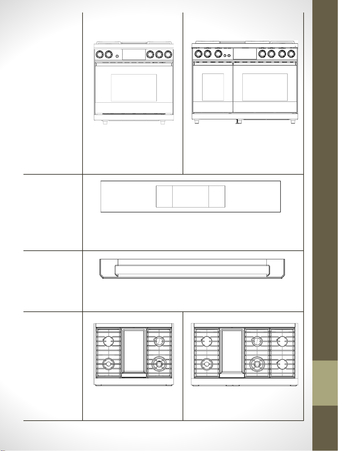
UNIT
CONTROL
36” Pro range
48” Pro range
Flat aluminum
(BLACK or SILVER)
HANDLE
COOKTOP
4 burners + 1 griddle
Flat aluminum
(BLACK or SILVER)
6 burners + 1 griddle
Page 3
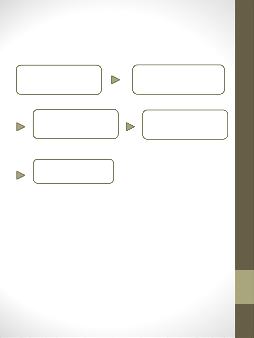
PLANNING CHECK PROCESS
PLANNING CHECK PROCESS
① A desired configuration
③ Check to make sure the location
where the appliance is to be installed
is free of obstructions and adheres to
product dimensions
⑤ Procure the proper installation
materials
② Plan the cabinet layout depending on
install method
④ Check proper location for the
electrical outlet and gas stub
Page 4
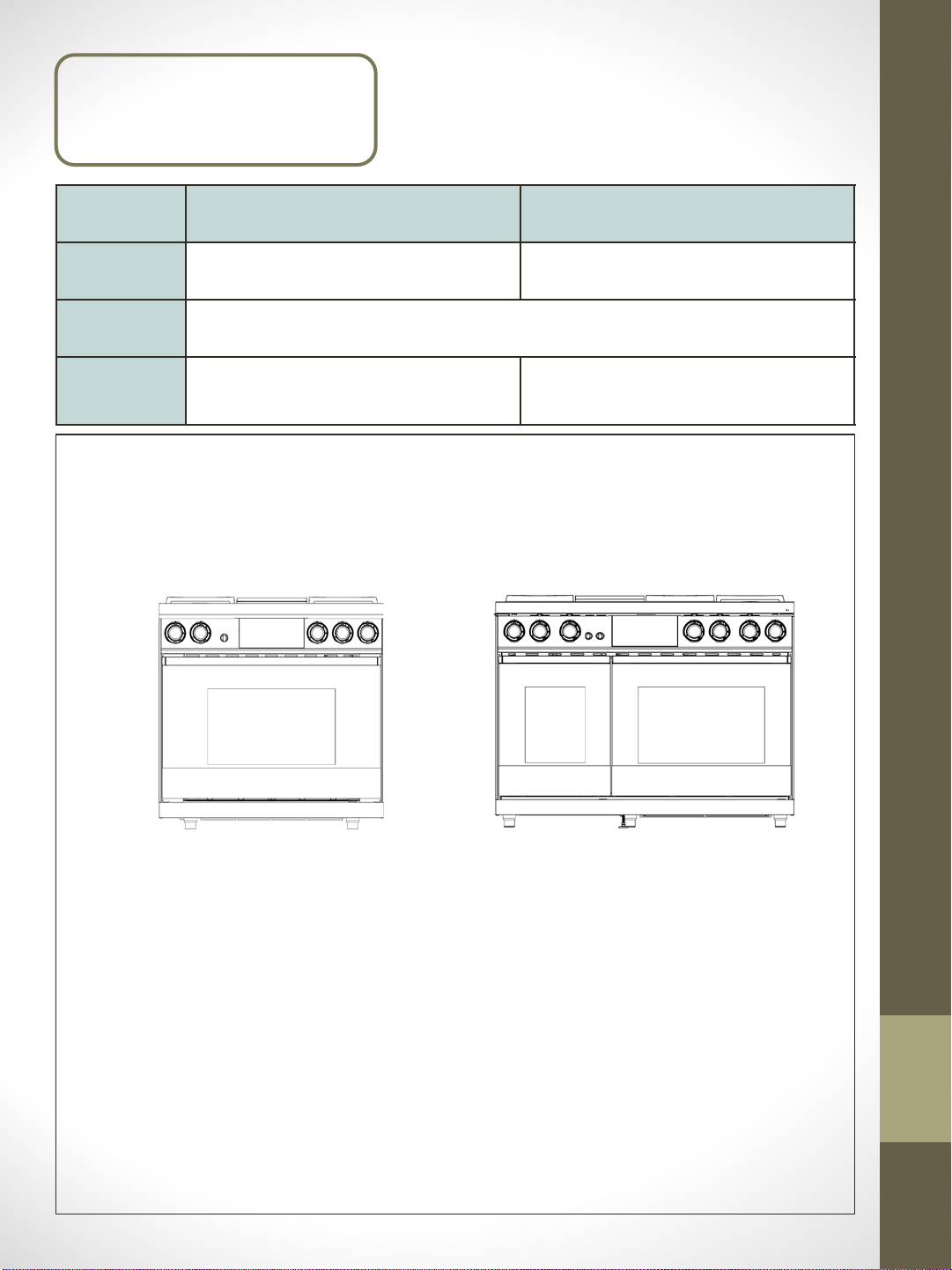
① A desired configuration
36” Pro range 48” Pro range
Width 36” 48”
COLOR Stainless Steel, Black Stainless steel(DLC coating)
COOKTOP 4 burners + 1 griddle 6 burners + 1 griddle
Pro Range
Configuration
DOP36M94DLS (Silver)
DOP36M94DLM (Black)
DOP48M96DLS (Silver)
DOP48M96DLM (Black)
Page 5

② Plan the cabinet layout
depending on install method
Standard Cutout with Range Hood
Appliance dimensions
CUTOUT DIMENSIONS
Range Model A B C
DOP36M94DL*
DOP48M96DL*
* Recommended ** Minimum *** Maximum
42” (106.7 cm)*
36” (91.4 cm)**
54” (137.2 cm)*
48” (121.9 cm)**
36” (91.4 cm)**
36 1/8” (91.7 cm)***
48” (121.9 cm)**
48 1/8” (122.2 cm)***
33 ½”
(84.8 cm)
9”
(22.9 cm)
Page 6

② Plan the cabinet layout depending on
install method
¹ Vertical distance from range grate level to combustible overhead surface; if installing an
overhead vent hood, also check hood specifications for minimum required clearances.
² Cabinet/countertop depth is at the discretion of customer but cabinet face MUST NOT
protrude further than rear of front panel, see product dimensions.
³ Consult local code for exact location requirements.
⁴ Vertical distance from grate level to combustible surface.
⁵ This specification does not apply for cabinets more than a horizontal distance of 10” (25.4 cm)
from the edge of the range.
Appliance dimensions
Page 7

③ Check to make sure the location
where the appliance is to be installed
is free of obstructions and adheres to
product dimensions
Product dimension
Cabinet dimensions
Page 8

④ Check proper location for the
electrical outlet and gas stub
DOP48M96DL*
DOP36M94DL*
Page 9

Electrical requirements
WARNING
• Failure to follow these instructions can result in death, fire, or electrical shock.
• It is the owner’s responsibility to make sure that the electrical service meets electrical
requirements and that the electrical outlet has been properly installed by a licensed electrician
to reduce the risk of fire, electric shock, or personal injury.
All ranges
• Do not use an extension cord or adapter plug with this range.
• This range must be properly grounded.
• Check with a qualified electrician if you are in doubt as to whether your range is properly
grounded.
• Do not modify the range power plug. If it does not fit the outlet, have a proper outlet
installed by a qualified electrician.
• All wiring and grounding must comply with local codes or, in the absence of local codes, with
the National Electrical Code, ANSI/NFPA No. 70 – Latest Revision (US), or the Canadian
Electrical Code CSA C22.1 – Latest Revisions and local codes.
• Wiring diagram is located on the back of the range. (Inside envelope)
• The range’s electronic ignition system will not operate if the outlet is not properly polarized.
• A dedicated circuit breaker is recommended.
• Use the chart below to determine the minimum recommended dedicated circuit protection.
KW Rating (240 V) Recommended Circuit Size (Dedicated)
36” Pro Range: 7.3 KW - 9.6 KW 40 Amp
48” Pro Range: 9.7 KW - 12.0 KW 50 Amp
Page 10

Gas requirements
Provide adequate gas supply.
The installation of this appliance must conform with local codes or, in the absence of local
codes, with the National Fuel Gas Code, ANSI Z223.1/NFPA 54.
The cooktop of this range is designed to operate at a manifold pressure of 5 in (13 cm) of
water column on natural gas.
Be certain that the appliance being installed is correct for the gas service provided (natural
gas).
When checking for proper operation of the regulator, the inlet pressure must be at least 1
in (2.5 cm) greater than the operating (manifold) pressure as given.
GAS SUPPLY PRESSURE REQUIREMENTS*
Gas Type Minimum Manifold Pressure Minimum Gas Supply Pressure**
Natural Gas 5” Water Column 6” Water Column
* The gas supply pressure for testing the regulator setting shall be at least 1 inch water
column (249 Pa) above the specified manifold pressure.
** Maximum gas supply pressure for all models: 1/2 psi.
The pressure regulator located at the inlet of the cooktop manifold must remain in the supply
line regardless of whether natural or LP gas is being used.
NOTE
• The cooktop has its own regulator. Use only the provided regulator, which must be installed
in the gas line that runs from the cooktop gas inlet to the gas shut-off valve.
• An external manual shut-off valve must be installed between the gas inlet and the cooktop
for turning on/off gas to the appliance.
• Be sure the connectors are installed by a qualified installer.
• For a new product, never install used connectors, which can leak gas and cause personal
injury. Use only new, flexible connectors.
Page 11

⑤ Procure the proper
installation materials
Preparation for install
Manual Screw (6)
Anti Tip Brackets (2) *
Gas line shut-off
valve
135-degree elbow
(optional)
(M4 L10 2 each, M4 L16 2ea,
24 3/16 UNC L145 nut toggle 2 each)
Flexible metal
Appliance connector
½ in (ID) x 5 ft.
Lag bolt or ½-in (OD)
sleeve anchor
Flare union adapter ¾
in (NPT) x ½ in (ID)
Regulator (1) *
Flare union adapter ½
In (NPT) x ½ in (ID)
Flat-blade
screwdriver
¼” Nut driver Pencil and ruler Level Pipe joint compound
Phillips screwdriver
Soapy water solution Utility knife
Open-end or
adjustable wrench
Pipe wrench (2)
Page 12

36-Inch ProRange
DOP36M94DLS / DOP36M94DPS
DOP36M94DLM / DOP36M94DPM
Color Silver STSS / Graphite STSS (DLC Coating)
Installation Type Freestanding
Cooking Zones 6 ( 1 Oven, 4 Burners, 1 Griddle)
Oven Capacity(cu.ft) 4.8
Bake, Broil, Convection Bake, Convection Roast
Convection Broil, Dual Four Part Pure Convection
Pure Conv.Sear, Steam Bake, Steam Roast
Keep Warm(3Hr), Low Proof, Proof, Stone Mode
Dehydrate, Gourmet Cook(15ea), InstantHeat
General
Control
Smart
Accessory
Oven Mode
Oven
Electric
Power
Griddle
Burners
Automatic Reignition
LED Shower Lighting
Bake(Hidden) 3,000W
Broil 4,400W
Convection 1,300W + 1,300W (Dual Heat Element)
Steam Heater 500W
Type Electric-1400W, Embedded
Material Al + Ceramic Coating
Total BTU 65,000 (65K)
Right Front 22K, Dual, Brass
Left Front 18K, Dual, Brass
Cleaning Method Self-clean / GreenClean™ / Descale / Draining
LED Knob Backlit
Wi-Fi (LTE) Module Oven Control, Cooktop Monitoring
Left Rear 16K, Stack Dual, Brass
Right Rear 9K, Stack Dual, Brass
Simmer(Min.) 700 BTU (@Right Front 22K Burner)
Sealed Burner
Energy Source Gas (NG/LP) and Electirc
Grate Type Porcelain coated continuous Cast Iron
Display / Type 7” Touch LCD / Knob & Touch
Bluetooth Auto Hood Connect, Auto Hood ON/Off
Grate 2 pcs
Brass Cap
Wok Ring
Rack Wire Rack(1pcs), Glide Rack(2pcs)
Steam Tray -
Etc. Temp. Probe(1pcs), Conv. Filter(2pcs)
●
●
●
●
●
●
Product Specification
Total Power
Product Width
Product Height
Product Depth
Cutout Width
Cutout Height
Cutout Depth
Watts(W)
Circuit Breaker(A)
Electrical Supply
Power Cord
Net Weight (lbs.)
65KBTU + 1.4KW
35 7/8"
36 1/8"
28 1/8"
36" (Min.)
36 3/16" ~ 37 1/2"
24" (Min.)
7,900 W
40A
240VAC/60Hz
Fixed Type(4 prong)
418 7/8 lbs (190 Kg)
Page 13

48 Inch ProRange
DOP48M96DLS / DOP48M96DPS
DOP48M96DLM / DOP48M96DPM
Color Silver STSS / Graphite STSS (DLC Coating)
Installation Type Freestanding
Cooking Zones 9 ( 2 Oven, 6 Burners, 1 Griddle)
Oven Capacity(cu.ft) 1.8 (Steam Oven) / 4.8 (Convection Oven)
Bake, Broil, Convection Bake, Convection Roast
Convection Broil, Dual Four Part Pure Convection
Pure Conv.Sear(L), Pure Steam(S), Steam Bake(S),
Steam Roast(S), Special Steam Cook(3ea, S)
Keep Warm(3Hr), Low Proof, Proof, Stone Mode(L)
Dehydrate(L), Gourmet Cook(15eaL), InstantHeat(L)
General
Control
Smart
Accessory
Oven Mode
( S : Small Cavity
L : Large Cavity )
Oven
Electric
Power
(1.8 / 4.8)
Griddle
Burners
Automatic Reignition
LED Shower Lighting
Bake(Hidden) 1,000W 3,000W
Broil 2,400W 4,400W
Convection 2,000W 1,300W + 1,300W (Dual)
Steam Heater 2,000W -
Type Electric-1400W, Embedded
Material Al + Ceramic Coating
Total BTU 97,000 (97K)
Center Front 22K, Dual, Brass
Center Rear 16K, Stack Dual, Brass
Right Front 9K, Stack Dual, Brass
Left Front 18K, Dual, Brass
Cleaning Method Self-clean / GreenClean™ / Descale / Draining
LED Knob Backlit
Wi-Fi (LTE) Module Oven Control, Cooktop Monitoring
Left Rear 16K, Stack Dual, Brass
Right Rear 16K, Stack Dual, Brass
Simmer(Min.) 700 BTU (@Right Front 22K Burner)
Sealed Burner
Energy Source Gas (NG/LP) and Electirc
Grate Type Porcelain coated continuous Cast Iron
Display / Type 7” Touch LCD / Knob & Touch
Bluetooth Auto Hood Connect, Auto Hood ON/Off
Grate 3 pcs
Brass Cap
Wok Ring
Rack Small Wire Rack(1pcs), Wire Rack(1pcs), Glide Rack(2pcs)
Steam Tray Steam Tray(2pcs), Half Steam Tray(2pcs)
Etc. Temp. Probe(2pcs), Conv. Filter(3pcs)
●
●
●
●
●
●
Product Specification
Total Power
Product Width
Product Height
Product Depth
Cutout Width
Cutout Height
Cutout Depth
Watts(W)
Circuit Breaker(A)
Electrical Supply
Power Cord
Net Weight (lbs.)
97KBTU + 1.4KW
47 7/8"
36 1/8"
28 1/8"
48" (Min.)
36 3/16" ~ 37 1/2"
24" (Min.)
10,300 W
50A
240VAC/60Hz
Fixed Type(4 prong)
540 1/8 lbs (245 Kg)
 Loading...