

Page 1

Modernist Pro Range
DOP48M96DL*/DOP36M94DL*
Installation Instructions
Page 2

Contents
Contents
Before you begin 5
Important 5
About this manual 6
Important note to the installer 6
Important note to the consumer 6
Important note to the servicer 6
Customer service information 7
Important safety instructions 8
Read all instructions before using this appliance 9
Symbols used in this manual 9
Product specifications 21
What's in the box 21
Installation requirements 24
Pre-installation checklist 24
General requirements 24
Location requirements 28
Gas requirements 31
Special gas requirements (gas models sold in Massachusetts) 32
Electrical requirements 33
Installation instructions 34
Preparing for installation 34
Installing the knobs for surface burners 54
Cooktop assembly 55
Verifying proper operation 60
Removal and Re-installation 63
Installation checklist 64
English2
Page 3

To Our Valued Customer:
Congratulations on your purchase of the very latest in Dacor® products! Our unique
combination of features, style and performance make us The Life of the Kitchen™, and a
great addition to your home.
In order to familiarize yourself with the controls, functions and full potential of your new
Dacor Appliance, read this use and care manual thoroughly, beginning with the Before you
begin section.
All Dacor appliances are designed and manufactured with quality and pride, while working
within the framework of our company value. Should you ever experience a problem with
your product, please first check the Troubleshooting section of this manual for guidance. It
provides useful suggestions and remedies prior to calling for service.
Valuable customer input helps us to continuously improve our products and services, so
please feel free to contact our Customer Service Team for assistance with any of your
product support needs.
Dacor Customer Service Team
14425 Clark Avenue
City of Industry, CA 91745
Telephone: (800) 793-0093
Fax: (626) 403-3130
Hours of Operation: Monday through Friday 6:00 A.M. to 5:00 P.M. Pacific Time
Website: www.Dacor.com
Thank you for choosing Dacor for your home. We are a company built by families for
families, and we are dedicated to serving yours. We are confident that your new Dacor
product will deliver a high level of performance and enjoyment for many years to come.
Sincerely,
English 3
Page 4

WARNING: Failure to follow the instructions in this manual exactly
may cause a fire or explosion, and, consequently, property damage,
personal injury, or death.
• DO NOT keep or use gasoline or other flammable products near
this appliance.
• IF YOU SMELL GAS:
- DO NOT light any appliances.
- DO NOT touch any electrical switches.
- DO NOT use any phone in your building.
- Immediately call your gas supplier from a neighbor's phone,
and follow the supplier's instructions. (If you cannot reach
your gas supplier, call the fire department.)
• Installation and service must be performed by a qualified
installer, service agency, or the gas supplier.
English4
Page 5

Before you begin
Important
• The overall design and/or accessories may
differ with the model.
Installer
• To promote safety and minimize
problems, read this manual thoroughly
before starting the installation. Leave
this manual with the user.
• Write the appliance’s model/serial
numbers in this manual for service/
maintenance reference.
User
• Keep this manual for personal reference
and for that of inspectors, service
personnel, etc.
Contents
English 5
Page 6

Before you begin
About this manual
READ THESE INSTRUCTIONS COMPLETELY AND CAREFULLY.
Important note to the installer
• Read all instructions contained in these installation instructions before installing the
Before you begin
cooktop.
• Remove all packing materials from the cooktop compartments before connecting the
electric and gas supply to the cooktop.
• Observe all governing codes and ordinances.
• Be sure to leave these instructions with the consumer.
• Installation of this appliance requires basic mechanical skills.
• Proper installation is the responsibility of the installer.
• Product failure due to improper installation is not covered under the Warranty.
Important note to the consumer
Keep these instructions with your user manual for future reference.
• As when using any appliance generating heat, there are certain safety precautions you
should follow.
• Be sure your cooktop is installed and grounded properly by a qualified installer or
service technician.
• Make sure the wall coverings around the cooktop can withstand the heat generated by
the cooktop.
• Cabinet storage space above the cooktop burners should be a minimum of 30 in
(76.2 cm).
Important note to the servicer
The electrical diagram is attached inside the burner box.
English6
Page 7

Customer service information
If you have questions or problems with installation, contact your Dacor dealer or the
Dacor Customer Service Team. For repairs to Dacor appliances under warranty call the
Dacor Distinctive Service line. Whenever you call, have the model and serial number of
the appliance ready. The serial number can be found on the inner side of door trim.
Dacor Customer Service Team Phone: (800) 793-0093 ex. 2813 (U.S.A. and Canada)
Monday — Friday 6:00 a.m. to 5:00 p.m. Pacific Time
Web site: www.dacor.com
Dacor Distinctive Service (for repairs under warranty only) Phone: (800) 793-0093 ex.
2822 (U.S.A. and Canada) Monday — Friday 6:00 a.m. to 5:00 p.m. Pacific Time
Customer service information
Model and Serial Number Location
English 7
Page 8

Important safety instructions
ANTI-TIP DEVICE
WARNING
ALL RANGES CAN TIP, RESULTING IN PERSONAL INJURY.
TIPPING RANGES CAN CAUSE BURNS FROM SPILLS,
PERSONAL INJURY, AND/OR DEATH.
INSTALL AND CHECK THE ANTI-TIP BRACKET FOLLOWING
THE INSTRUCTIONS AND TEMPLATE SUPPLIED WITH THE
BRACKET.
• To prevent accidental tipping of the range, attach an approved
Important safety instructions
anti-tip device to the floor. (See Installing the Anti-Tip Device
in the Installation Instructions.) Check for proper installation by
carefully tipping the range forward. The anti-tip device should
engage and prevent the range from tipping over.
• If the range is pulled out away from the wall for any reason, make
sure the anti-tip device is reengaged after the range has been
pushed back into place.
• Follow the installation instructions found in the Installation
Manual. Failure to follow these instructions can result in death,
serious personal injury, and / or property damage.
• DO NOT step / sit / lean on the door or drawer to prevent
accidental tipping of the range.
English8
Page 9

READ ALL INSTRUCTIONS BEFORE USING THIS APPLIANCE
• Electrical and gas equipment with moving parts can be dangerous. The important
safety instructions in this manual are intended to minimize the risk of property
damage, personal injury, and death. Be sure to read them.
• Keep this manual in a handy place so you can refer to it as needed.
Symbols used in this manual
WARNING
Hazards or unsafe practices that may result in severe personal injury or death.
CAUTION
Hazards or unsafe practices that may result in electric shock, personal injury, or property
damage.
NOTE
Useful tips and instructions.
These warning icons and symbols are intended to prevent property damage and personal
injury. Follow them explicitly.
Important safety instructions
English 9
Page 10

Important safety instructions
State of California Proposition 65 Warning (US only)
WARNING: This product contains chemicals known to the State of California to cause
cancer and birth defects or other reproductive harm.
Gas appliances can cause low-level exposure to Proposition 65 listed substances (including
benzene, carbon monoxide, formaldehyde, and soot) resulting from the incomplete
combustion of LP or natural gas.
Commonwealth of Massachusetts
This product must be installed by a licensed plumber or gas fitter qualified or licensed by
the State of Massachusetts. When using ball-type gas shut-off valves, you must use the
T-handle type. Multiple flexible gas lines must not be connected in series.
General safety
Important safety instructions
WARNING
To reduce the risk of fire, electric shock, personal injury, or death, observe these
precautions:
• Do not touch any surface, component,
or mechanism of the product during or
immediately after cooking.
• Learn where and how to shut off the
valve that feeds gas to the product.
• Make sure the anti-tip device is properly installed. (See the Installation Instructions for
details.)
• Do not let children sit/stand on the product or play with any of its parts. Do not leave
children unattended in the kitchen when the product is in use.
• Remove all packaging before operating the product to keep this material from catching
fire. Keep all packaging away from children. Properly dispose of packaging as soon as
the product is unpacked.
• Do not keep objects of interest to children on or around the product.
• Do not operate the product if it is damaged in any way, if it malfunctions, or is missing
parts.
English10
Page 11

• Do not use the product as a space heater. This product is to be used for cooking
purposes only.
• Do not use oven cleaners or oven liners in or around any part of the oven.
• Use only dry pot holders.
• Do not use the product to heat unopened food containers.
• Do not strike the oven glass.
• When disposing of the range, cut off the power cord and remove the door.
• Unplug the product before service/maintenance.
• Make sure all meat and poultry is cooked thoroughly. Meat should always be cooked
to an internal temperature of 160 °F (71 °C). Poultry should always be cooked to an
internal temperature of 180 °F (82 °C).
• An air curtain or other overhead range hood, which operates by blowing a downward
airflow onto a range, shall not be used in conjunction with a gas range unless the
hood and range have been designed and tested in accordance with the Standard
for Domestic Gas Ranges, ANSI Z21.1 • CSA1.1, and listed by an independent testing
laboratory for combination use.
WARNING
NEVER use this appliance as a space heater to heat or warm the room. Doing so may
result in carbon monoxide poisoning and overheating of the oven.
Important safety instructions
English 11
Page 12

Important safety instructions
Fire safety
WARNING
To reduce the risk of fire, electric shock, personal injury, or death, observe these
precautions:
• To avoid grease buildup, regularly clean the vents.
• Do not let pot holders or other flammable material touch a heating element. Do not use
Important safety instructions
a towel or other bulky cloth item as a pot holder.
• Do not douse a grease fire with water. Instead, turn off the heat source, and smother
the fire with a tight-fitting lid, or use a multi-purpose, dry-chemical or foam
extinguisher.
• If a grease fire should occur in the oven, turn off the oven by pressing the OFF button.
Keep the oven door closed until the fire goes out. If necessary, use a multipurpose dry
chemical or foam-type fire extinguisher.
• Do not heat unopened food containers - buildup of pressure may cause container to
burst and result in injury.
• Do not store/place/use combustible
materials (e.g., paper, plastic, pot
holders, linens, gasoline, alcohol) near
the product.
• Do not wear loose fitting or hanging
garments while using the product.
English12
Page 13

Gas safety
WARNING
To reduce the risk of fire, electric shock, personal injury, or death, observe these
precautions:
If you smell gas:
• Close the valve and do not use the product.
• Do not light a match, candle, or cigarette.
• Do not turn on any gas or electric appliances.
• Do not touch any electrical switch or plug in a power cord.
• Do not use any phone in your building.
• Evacuate everyone from the building.
• Immediately call your gas supplier from a neighbor’s phone. Follow the gas supplier’s
instructions.
• If you cannot reach your gas supplier, call the fire department.
Checking for gas leaks
Leak-testing the appliance must be done according to the manufacturer’s instructions. Do
not use a flame to check for gas leaks. Use a brush to spread a soap-and-water solution
around the area you are checking. If there is a gas leak, small bubbles will appear in the
solution. When not sure, call for professional help.
Important safety instructions
English 13
Page 14

Important safety instructions
Electrical and grounding safety
WARNING
To reduce the risk of fire, electric shock, personal injury, or death, observe these
precautions:
• Do not put a fuse in a neutral or ground circuit.
Important safety instructions
• Use a dedicated 240 Vac, 60 Hz, 50 Amp breaker for the 48" Range and a 40 Amp
breaker for the 36" Range. A time-delay fuse or circuit breaker is recommended. Do not
plug more than one appliance into this circuit.
• Do not connect the ground wire to plastic plumbing lines, gas lines, or hot water pipes.
• This product must be grounded. If the range malfunctions or breaks down, grounding
reduces the risk of electric shock by providing a safe path for the current. This range's
power cord has a grounding plug, which must be firmly plugged into an outlet that is
properly installed and grounded according to local regulations. If you are not sure your
electrical outlet is properly grounded, have it checked by a licensed electrician.
• The range is supplied with a 4-pronged grounded plug. This cord must be plugged into
a mating, grounded 4-prong outlet that meets all local codes and ordinances. If codes
allow for a separate ground wire, you should have a qualified electrician determine this
wire's proper path.
• Electrical service to the range must conform to local codes, or in the absence of local
codes, to the National Electrical code/NFPA No. 70 – Latest Revision (for the U.S.) or the
Canadian Electrical Code CSA C22.1 or Latest Revisions.
• The product owner shall ensure that the proper electrical service is provided for the
product.
• Plug into a grounded 3-prong outlet.
• Do not remove the ground prong.
• Do not use an adapter or an extension
cord.
• Do not use a damaged power plug,
power cord, or loose power outlet.
• Do not modify the power plug, cord, or
outlet.
English14
Page 15

Installation safety
WARNING
To reduce the risk of fire, electric shock, personal injury, or death, observe these
precautions:
• This product should be installed and
properly grounded by a qualified
installer, as specified in the Installation
Instructions. Adjustments and service
should be performed only by qualified
gas range installer or service technician.
• Do not try to service/modify/replace the product or any part of it unless specifically
recommended in this manual. All other service should be performed by a qualified
technician.
• Use only new, flexible connectors when installing the product.
• Make sure the anti-tip device is properly installed. (See the Installation Instructions for
details.)
• Due to the size and weight of the range, have two or more people move the range.
• Remove all tape and packaging materials.
• After unpacking the product, remove all accessories from inside and around it.
(Cautiously handle the heavy grates.)
• Make sure no parts came loose during shipping.
• Make sure the product is correctly installed/adjusted by a qualified service technician
or installer for the type of gas (natural or LP) you will use. For the range to use LP gas,
the installer must replace every surface burner orifices with the provided LP orifice
set, and reverse the GPR adapter. These adjustments must be made by a qualified
technician according to manufacturer instructions and local regulations. The qualified
agency performing this work shall be responsible for the gas conversion.
• Installation of this range must conform with local codes or, in the absence of local
codes, with the National Fuel Gas Code, ANSI Z223.1/NFPA.54, latest edition. In Canada,
installation must conform with the current Natural Gas and Propane Installation Code,
CAN/CGA-B149.1, or the current Propane Installation Code, CAN/CGA-B149.2, and with
local codes where applicable. This range has been design-certified by UL according to
ANSI Z21.1/CSA 1.1, latest edition.
Important safety instructions
English 15
Page 16

Important safety instructions
Location safety
WARNING
To reduce the risk of fire, electric shock, personal injury, or death, observe these
precautions:
• This range is for indoor household use
only. Do not install the range outdoors
or anywhere that it will be exposed to
weather/water or wind/ strong drafts.
Important safety instructions
• Select a level, well-constructed floor that can support the range’s weight. Synthetic
flooring, such as linoleum, must withstand 180 °F (82 °C) temperatures without
shrinking, warping, or discoloring. Do not install the range directly over interior kitchen
carpeting unless a sheet of ¼ inch plywood or a similar insulator is placed between the
range and carpeting.
• The range must be installed within easy reach of a grounded, 3-prong outlet.
• Do not hang paper blinds on a window near the range; do not hand long curtains that
could be blown over/onto the range.
• For proper ventilation, the range needs sufficient space below and all around the
chassis. Vents in the chassis exhaust heat and fumes so the range can operate properly.
• Make sure the wall coverings around the range can withstand heat up to 194 °F (90 °C)
generated by the range.
• Cabinet storage above the surface of the range should be avoided. If cabinet storage
above the range is necessary: allow a minimum clearance of 30 inches (76.2 cm)
between the cooking surface and the bottom of cabinets; or install a range hood that
projects horizontally a minimum of 5 inches (12.7 cm) beyond the bottom of the
cabinets.
English16
Page 17

Cooktop safety
WARNING
To reduce the risk of fire, electric shock, personal injury, or death, observe these
precautions:
• Make sure all burners are off when not
in use.
• Do not use aluminium foil to line the
grates or any part of the cooktop.
• Do not leave burners unattended on
medium or high heat settings.
• Before igniting, make sure all burner
caps are properly in place and all
burners are level.
• Always use the LITE position to ignite a burner, then make sure the burner has ignited.
If ignition fails, turn the knob to OFF, and wait a few minutes for the gas to dissipate.
• When you set a burner to simmer, do not turn the knob quickly. Make sure the flame
stays on.
• Do not place any objects other than cookware on the cooktop.
• This cooktop is designed to cook with a wok or wok ring attachment. If foods are
flamed, they should only be flamed under a ventilation hood that is on.
• Before removing or changing cookware, turn off the burners.
• Remove food and cookware immediately after cooking.
• Make sure all cooktop burners are off and all surfaces have completely cooled before
removing the grates and disassembling the burners.
• After cleaning the burner head, make sure it is completely dry before re-assembling.
• Make sure the spark mark on the dual burner spreader is placed beside the electrode
when it is assembled.
• To avoid carbon monoxide poisoning, do not pour water or other liquids into the
cooktop during cleaning.
• Select cookware that is designed for cooktops and that is large enough to cover the
grates. Burner flames should not extend beyond the bottom of the cookware.
• To avoid cookware discoloration, deformity, and/or carbon monoxide poisoning, do not
use cookware that is exceedingly larger than the grate.
• Turn cookware handles to the side or rear of the cooktop and not over active burners
or the front edge of the cooktop.
• Stand at a safe distance while frying to avoid hot spatter.
Important safety instructions
English 17
Page 18

Important safety instructions
• When frying, always heat the oil slowly, and monitor the oil as it heats. When frying
foods at high heat, monitor the oil throughout the cooking process. If combining fats or
oils for frying, mix them together before heating.
• Use a deep-fry thermometer when possible to avoid heating the oil beyond its smoke
point. (Know the smoke point of the oil you are using.)
• Always use a minimum amount of oil for any type of frying. Always thaw food before
frying, and do not frying food that is overly cold or that has clumps of ice attached to
it.
• Always let the oil/fat in the cookware to cool to room temperature before moving the
cookware.
• To avoid delayed-eruptive boiling, let hot oil/fat stand at least 20 seconds after turning
off the burner so the temperature can stabilize. In the event of scalding, follow these
first-aid instructions:
1. Immerse the scaled area in cool or lukewarm water for at least 10 minutes.
2. Do not apply any creams, oils, or lotions.
Important safety instructions
3. Cover with a clean, dry cloth.
Oven safety
WARNING
To reduce the risk of fire, electric shock, personal injury, or death, observe these
precautions:
• Do not use the oven for non-cooking
purposes such as drying clothes or
storage. Use the oven for cooking
purposes only.
• Make sure the oven racks are placed on the same level on each side.
• Do not damage, move, or clean the door gasket.
• Do not spray water on the oven glass while the oven is on or just after you have
turned it off.
• Do not use aluminium foil or foil liners anywhere in the oven. Do not use aluminium
foil or like material to cover any holes or passages in the oven bottom or to cover an
oven rack.
• Stand away from the oven when opening the oven door.
English18
Page 19

• Keep the oven free from grease buildup.
• When repositioning the oven racks, make sure the oven is completely cool.
• Do not leave plastic items inside the oven.
• To avoid damaging the burner control knobs or oven control, always bake and/or broil
with the oven door closed.
• Do not broil meat too close to the broil element. Trim excess fat from meat before
cooking.
• When using cooking or roasting bags in the oven, follow the manufacturer’s directions.
• Do not use harsh abrasive cleaners or sharp metal scrapers to clean the oven door
glass. They can scratch the surface which may result in the glass shattering.
CAUTION
• Do not attempt to operate the oven during a power failure.
• If the power fails, always turn the oven off. If the oven is not turned off and the power
returns, the oven may begin to operate again. Food left unattended could catch fire or
spoil.
Important safety instructions
English 19
Page 20

Important safety instructions
Self-cleaning oven safety
WARNING
To reduce the risk of fire, electric shock, personal injury, or death, observe these
precautions:
• Keep children away from the oven during a self-cleaning cycle.
• Before starting a self-cleaning cycle, remove all racks, cookware, and utensils from the
oven. Only porcelain-coated oven racks may be left in the oven.
Important safety instructions
• Before operating the self-clean cycle, wipe grease and food soils from the oven.
• Excessive amounts of grease may ignite, leading to smoke damage to your home.
• When opening the door after a self-cleaning cycle, stand away from the oven.
• If the self-cleaning cycle malfunctions, turn off the oven, turn off the power breaker,
and contact a qualified service technicia.
• Never keep pet birds in the kitchen. Birds are extremely sensitive to the fumes
released during an oven self-clean cycle. Fumes may be harmful or fatal to birds. Move
birds to a well-ventilated room.
• Do not use any commercial oven cleaner or oven liner protective coating of any kind in
or on the outside of the oven.
• Remove the nickel oven shelves from the oven before you begin the self cleaning cycle
or they may discolor.
• Excess spillage must be removed before you run the self-cleaning cycle.
• The self-cleaning feature operates the
oven at temperatures high enough
to burn away food soils in the oven.
The range is extremely hot during a
self-cleaning cycle. Do not touch any
surfaces of the range during a selfcleaning cycle.
English20
Page 21

Product specifications
What's in the box
Parts list - DOP48M96DL*
Grates (3) Burner heads (6) and Burner
caps (7)
Convection filter (3) Temp. Probe (2) Glide racks (2)
WOK ring (1) Anti-tip bracket (1) Wire rack (1)
Griddle (1)
Product Specifications
Small rack (1)* Steam tray (2)* Half steam tray (2)*
NOTE
• The range is supplied with two different types of burner caps (brass and porcelain) to
suit the customer’s preference.
• Parts with asterisk (*) is only for Steam oven.
English 21
Page 22

Product Specifications
Parts list - DOP36M94DL*
Grates (2) Burner heads (4) and Burner
Product Specifications
Convection filter (2) Temp. Probe (1) Glide racks (2)
Griddle (1) WOK ring (1) Anti-tip bracket (1)
The range is supplied with two different types of burner caps (brass and porcelain) to suit
the customer’s preference.
Wire rack (1)
caps (5)
English22
Page 23

Parts needed
Gas line shut-off valve Flexible metal appliance
connector ½ in (ID) x 5 ft
135-degree elbow
(optional)
Lag bolt or ½-in (OD)
sleeve anchor
Tools needed
Flat-blade
screwdriver
Phillips
screwdriver
adjustable wrench
Open-end or
Flare union adapter ¾ in
(NPT) x ½ in (ID)
Flare union adapter ½ in
(NPT) x ½ in (ID)
Product Specifications
Pipe wrench (2)
Nut driver Pencil and ruler Level Pipe joint
compound
Utility knife Soapy water
solution
English 23
Page 24

Installation requirements
Pre-installation checklist
1. Before preparing the opening in the countertop or cabinet, verify that there will be no
conflict between the range and anything in the cabinet below.
2. Remove packing materials, grate boxes, regulator with literature, and literature
package from the range, verify that all items are present before beginning the
installation.
General requirements
Clearances and dimensions
• For OTR over Gas Stove, please follow local GAS CODE.
• BEFORE YOU BEGIN to install this appliance, refer to the following information,
dimensions, and clearances. Do not locate the range where it may be subject to strong
drafts. Provide adequate clearances between the range and adjacent combustible
surfaces. These dimensions must be met for safe use of the range. The location of the
electrical outlet and gas piping may be adjusted to meet the following dimensions and
clearances.
• The range may be installed flush to the rear wall. Dacor strongly recommends installing
a non-combustible material on the rear wall above the range and up to the vent hood
or installation of a backguard. It is not necessary to install non-combustible materials
Installation requirements
behind the range below the countertop height. Any openings in the wall behind the
appliance or in the floor underneath it must be sealed.
• For installation in Canada, a free-standing range is not to be installed closer than 4.7 in
(12 cm) from any adjacent surface.
CAUTION
This range has been designed to comply with the maximum allowable wood cabinet
temperature of 194 °F (90 °C). Make sure the wall covering, countertops, and cabinets
around the range can withstand the heat (up to 194 °F [90 °C]) generated by the range. If
not, discoloration, delamination, or melting may occur.
English24
Page 25

Minimum dimensions
WARNING
If overhead cabinets are provided, a range hood should also be provided that
projects horizontally a minimum of 5 in (12.7 cm) beyond the front of the cabinets.
This will dissipate any heat buildup in the overhead cabinets to prevent death,
personal injury, and/or fire hazard. The ventilating hood must be constructed of
sheet metal not less then 0.0122" thick. Install above the range with a clearance of not
less than 1/4" between the hood and the underside of the combustible
material or metal cabinet. The hood must be at least as wide as the appliance
and centered over the appliance. Clearance between the cooking surface and the
ventilation hood surface must never be less than 24 inches.
Exception : Installation of a listed microwave oven or cooking appliance over the
range shall conform to the installations packed with that appliance.
• 30 in (76.2 cm) minimum clearance between the top of the cooking surface and the
bottom of an unprotected wood or metal cabinet; or If no 30 in (76.2 cm) minimum
clearance, 24 in (61 cm) minimum when the bottom of the wood or metal cabinet is
protected by not less than 0.25 in (0.64 cm) flame-retardant millboard covered with
not less than no. 28 MSG sheet steel, 0.015 in (0.038 cm) stainless steel, 0.024 in
(0.061 cm) aluminum, or 0.020 in (0.051 cm) copper.
• 18 in (45.7 cm) minimum between the countertop and the adjacent cabinet bottom.
Installation requirements
English 25
Page 26

Installation requirements
Product dimensions
OTE
Product tolerances: ±1/16” (±1.6 mm)
Width: DOP36M94DL* - 35 7/8” (91.1 cm)
DOP48M96DL* - 47 7/8” (121.6 cm)
Installation requirements
24” (61.0 cm)
Cabinet face
48” (121.9 cm)
28 1/8” (71.4 cm)
27 1/2” (69.9 cm)
26” (66.0 cm)
23 15/16” (60.8 cm)
15/16” (2.4 cm) to
cooking surface (top of
grates) from top of trim
Finished side panel
Countertop
height:
36 3/16"
(91.9 cm) min.
37 1/2”
(95.3 cm) max.
Front of open door
Front of handle
Front edge of bull nose
Front panel
Rear of oven door
1 1/4”
(3.2 cm)
(91.8 cm)
29 7/8” (75.9 cm)***
Back of
control
panel
Cabinet face
DOP36M94DL* or
DOP48M96DL* Range
Countertop*
*
X
36 1/8"
* The optional backguard is
available in two heights; 3
and 9 inches high.
3/8” min. (1.0 cm)
flat countertop
overhang required
behind cutout
Stiffener
3/8” min. (1.0
cm) space behind
doendraft vent
chassis to clear
stiffener
ERV36-ER or
ERV48-ER
downdraft vent
View of Range Installed
(Side View)
English26
View of Range Installed with Downdraft Vent
(Side View)
Page 27

Cabinet dimensions
• All maximum and minimum dimensions and clearances shown in the diagrams below
must be maintained for safe operation.
• Check the location where the range is to be installed. It should be placed away from
drafts that may be caused by doors, windows and heating and air conditioning outlets.
• To reduce the risk of fire or personal injury from reaching over a hot appliance, avoid
cabinet installations directly above the range. If cabinet storage is to be provided, the
risk can be reduced by installing a range hood that projects horizontally a minimum of
5 inches beyond the bottom of the cabinets.
CUTOUT DIMENSIONS
Range Model A B C
DOP36M94DL*
DOP48M96DL*
42” (106.7 cm)*
36” (91.4 cm)**
54” (137.2 cm)*
48” (121.9 cm)**
* Recommended ** Minimum *** Maximum
Standard Cutout with Range Hood
A
13” (33.0 cm)
5
max.
Non-combustible
surface along back wall
recommended
Top of
finished
counter
30” (76.2 cm)
1
18” (45.7 cm)
37 1/2”
(95.3 cm)
max.
Note 2
min.
4, 5
Grate
level
B
Suggested
location of
3
utilities
36” (91.4 cm)**
36 1/8” (91.7 cm)***
48” (121.9 cm)**
48 1/8” (122.2 cm)***
non-combustible rear
wall recommended
10” (25.4 cm) min.
to combustible side
walls above the range
(both sides)
Cutout with Optional Downdraft Vent
Note 2
33 1/2”
(84.8 cm)
(22.9 cm)
Backsplash
3/8" (1.0 cm) min.
flat countertop
overhang
C
10" (25.4 cm) min.
to combustible side
walls above the range
(both sides)
B
(Top View)
9”
Installation requirements
3” (7.6 cm)
English 27
Page 28

Installation requirements
1
Vertical from range grate level to combustible overhead surface; if installing an
overhead vent hood, also check hood specifications for minimum required clearances.
2
Cabinet/countertop depth is at discretion of customer but cabinet face MUST NOT
protrude further than rear of front panel, see product dimensions.
3
Consult local code for exact location requirements.
4
Vertical from grate level to combustible surface.
5
This specification does not apply for cabinets more than a horizontal distance of 10”
(25.4 cm) from the edge of the range.
Location requirements
DOP48M96DL*
20.6 cm
(8 1/8")
Installation requirements
67.6 cm
(26 5/8")
16.8 cm
(6 5/8")
13.9 cm
(5 1/2")
Gas Inlet
Back of range
Shown with
electrical access
cover removed
E - Electrical wiring
access hole in bottom
English28
Page 29

DOP36M96DL*
28.4 cm
(11 3/16")
Gas Inlet
Back of range
61.6 cm
(24 1/4")
Shown with
electrical access
cover removed
16.8 cm
(6 5/8")
22.5 cm
(8 7/8")
1
Measurement with appliance legs adjusted to lowest height.
2
The hole size for the electrical wiring may be increased to 1 1/8” (2.9 cm) by removing
the conduit bracket in the bottom of the range electrical box.
Installation requirements
English 29
Page 30

Installation requirements
Gas and Electrical Service
• The shaded area shown below denotes the location of the gas inlet and the electrical
junction box/receptacle. This is the recommended location. For replacement purposes,
the location of the existing utilities may be utilized provided they do not interfere with
the sides or rear of the range. Check local building codes for permissible gas valve
locations.
• An external manual shut-off valve must be installed between the gas inlet and the
range for the purpose of turning on or shutting off gas to the appliance. The installation
must allow for the following:
• Access to the gas shut-off valve when the unit is installed.
• Access to the remote circuit breaker panel/fuse box, when the range is in place.
• The gas supply piping and shut-off valve, and the electrical junction box/receptacle
must be located so they do not interfere with the range when it is installed.
• The junction box and gas shut off valve must be located so that the range can be pulled
out for service while the appliance remains connected.
Installation requirements
Recommended
position for Gas stub
Recommended
position for
Electrical outlet
English30
Model D E F G
G
E
D
F
DOP36M94DL*
DOP48M96DL*
8 7/8"
(22.5 cm)
5 1/2"
(13.9 cm)
6 5/8"
(16.8 cm)
6 5/8"
(16.8 cm)
11 3/16"
(28.4 cm)
8 1/8"
(20.6 cm)
24 1/4"
(61.6 cm)
26 5/8"
(67.6 cm)
Page 31

Gas requirements
Provide adequate gas supply.
The installation of this appliance must conform with local codes or, in the absence of local
codes, with the National Fuel Gas Code, ANSI Z223.1/NFPA 54.
The cooktop of this range is designed to operate at a manifold pressure of 5 in (13 cm) of
water column on natural gas.
Be certain that the appliance being installed is correct for the gas service provided
(natural gas).
When checking for proper operation of the regulator, the inlet pressure must be at least 1
in (2.5 cm) greater than the operating (manifold) pressure as given.
GAS SUPPLY PRESSURE REQUIREMENTS*
Gas Type Minimum Manifold Pressure Minimum Gas Supply Pressure**
Natural Gas 5” Water Column 6” Water Column
* The gas supply pressure for testing the regulator setting shall be at least 1 inch water
column (249 Pa) above the specified manifold pressure.
** Maximum gas supply pressure for all models: 1/2 psi.
English 31
Installation requirements
Page 32

Installation requirements
The pressure regulator located at the inlet of the cooktop manifold must remain in the
supply line regardless of whether natural or LP gas is being used.
NOTE
• The rangetop has its own regulator. Use only the provided regulator, which must be
installed in the gas line that runs from the cooktop gas inlet to the gas shut-off valve.
• An external manual shut-off valve must be installed between the gas inlet and the
cooktop for turning on/off gas to the appliance.
• Be sure the connectors are installed by a qualified installer.
• For a new product, never install used connectors, which can leak gas and cause
personal injury. Use only new, flexible connectors.
Special gas requirements (gas models sold in Massachusetts)
COMMONWEALTH OF MASSACHUSETTS REQUIREMENTS:
WARNING
• Gas leaks may occur in your system, creating a dangerous situation.
- Gas leaks may not be detected by smell alone.
- Gas suppliers recommend installing a UL-approved gas detector according to
manufacturer specifications.
Installation requirements
• The range must be installed by a plumber or gas fitter certified by the State of
Massachusetts.
• A T-handle manual gas valve MUST be installed in the gas supply line to your product.
• If a flexible gas connector is used to install your cooktop, multiple flexible gas lines
must not be connected in series.
English32
Page 33

Electrical requirements
• Failure to follow these instructions can result in death, fire, or electrical shock.
WARNING
• It is the owner’s responsibility to make sure that the electrical service meets electrical
requirements and that he electrical outlet has been properly installed by a licensed
electrician.
• To reduce the risk of fire, electric shock, or personal injury:
All range
• Do not use an extension cord or adapter plug with this range.
• This range must be properly grounded.
• Check with a qualified electrician if you are in doubt as to whether your range is
properly grounded.
• Do not modify the range power plug. If it does not fit the outlet, have a proper outlet
installed by a qualified electrician.
• All wiring and grounding must comply with local codes or, in the absence of local
codes, with the National Electrical Code, ANSI/NFPA No. 70 – Latest Revision (US), or
the Canadian Electrical Code CSA C22.1 – Latest Revisions and local codes.
• Wiring diagram is located on the back of the range. (Inside of the cover back wire)
• The range’s electronic ignition system will not operate if the outlet is not properly
polarized.
• A dedicated circuit breaker is recommended.
• Use the chart below to determine the minimum recommended dedicated circuit
protection.
Installation requirements
KW Rating (240 V) Recommended Circuit Size (Dedicated)
7.3 KW - 9.6 KW 40 Amp
9.7 KW - 12.0 KW 50 Amp
English 33
Page 34

Installation instructions
Preparing for installation
WARNING
• If the gas or electric service provided does not meet the product specifications, do not
proceed with the installation. Call the dealer, the gas supplier or a licensed electrician.
• Before installing the range, you must locate and secure the anti-tip bracket to the floor.
NOTE
Within the Commonwealth of Massachusetts, this appliance must be installed by a licensed
plumber or gas fitter.
Unpacking the Range
Unpack the parts box and verify that all required components have been provided. If
any item is missing or damaged, please contact your dealer immediately. Do not install a
damaged or incomplete appliance.
Installing a Backguard (Optional)
Install the backguard before making the range gas and electrical connections. Install it
according the installation instructions included with the backguard kit.
Approved backguard kits:
Model Description
APB36D3 3 inch high backguard for range model DOP36M94DL*
APB36D9 9 inch high backguard for range model DOP36M94DL*
APB48D3 3 inch high backguard for range model DOP48M96DL*
APB48D9 9 inch high backguard for range model DOP48M96DL*
Install the Anti-Tip Bracket and Foot
Locate the anti-tip bracket included in the parts box.
Installation instructions
There are two ways to mount the anti-tip bracket:
• Floor mounting (preferred method)
• Wall mounting (alternate method). Use this method if floor mounting is not suitable. If
the front panel of range is further than 26 1/2” (67.3 cm) from the back wall or if the
flooring is too thick (see Installing the Anti-Tip Bracket on the Wall), the wall mounting
method may not be used and the floor mounting method must be suitable.
English34
Page 35

Installing the Anti-Tip Bracket on the Floor
WARNING
To perform its intended function, the anti-tip bracket must be attached as instructed to the
concrete slab or wood sub-floor below any floor coverings (including cement board) on
top. Do not attach the anti-tip bracket directly to floor coverings such as ceramic/asphalt
tile or linoleum.
Anti-tip bracket
Floor covering
Sub-floor
Screws attached to subfloor below floor covering
Concrete anchors shown, do not
use for wood sub-floor
Four (4) plastic anchors are provided along with three sizes (4 each) of #8 or #12 Phillips
head screws for attaching the anti tip bracket to the floor. Use both the anchors and
four (4) of the screws when attaching the bracket to a concrete sub-floor. Do not use the
provided anchors when attaching to a wood sub-floor.
1. Determine the location of the range center line and front panel for the range’s final
position based on the Product Dimensions on page 5 and the actual cabinet/cutout
dimensions used for the installation.
2. Determine the required position of the anti-tip bracket, based on the diagram below.
Mark the four (4) mounting hole locations on the floor with a pencil.
3. Determine the screw size required. The minimum full thread depth (portion of screw
threaded into wood/slab) for wood is 3/8” (1 cm) and 5/8” (1.6 cm) for concrete. See
SCREW SIZE TABLE to select the correct screw size.
Installation instructions
English 35
Page 36

Installation instructions
Attaching the bracket to a concrete floor:
• Drill four (4) 3/8” diameter countersink holes through any existing floor covering down
to the concrete slab below.
• Drill the 4 holes for the anchors 1 1/4” (3.2 cm) deep into the concrete slab using a
3/16” masonry bit. This hole length is longer than the anchor, but is required for proper
installation. Clear the holes of dust and any other material. Tap each anchor into the
hole until the anchor top is flush with the top of the concrete slab. Position the antitip bracket holes over the anchor holes. Insert the screws through the 4 holes in the
base of the bracket and thread them into the anchors. Be sure the screw threads fully
engage the anchor body. Tighten the screws into place.
Attaching the bracket to a wood floor:
• If there is ceramic, asphalt or other hard floor covering over the wood below, drill (4)
countersink holes to allow access to the wood below for drilling pilot holes.
• Drill four (4) pilot holes into the wood floor using a drill bit (1/16” dia. for #8 screws,
1/8” dia. for #12 screws). Position the anti-tip bracket holes over the holes in the floor.
Insert the screws into the wood and tighten into place.
TOP VIEW
Installation instructions
Dimension DOP36M94DL* DOP48M96DL*
A 13” (33.0 cm) 3 1/2” (8.9 cm)
B 22 1/2” (57.2 cm) 22 1/2” (57.2 cm)
#8 x 1” #8 x 1 1/4”
or #12 x 1 3/4 screw,
4 places (see text)
Anchor, 4 places:
use for concrete
floor only
Range
front panel
ANTI-TIP BRACKET PLACEMENT
Range center line
B
C
A
English36
Page 37

SCREW SIZE TABLE
Sub-Floor Type/Floor Covering Thickness Screw Size
Concrete or wood subfloor, no floor covering
over top
Concrete or wood subfloor, floor covering up
to 1/4” thick
Concrete or wood subfloor, floor covering
over 1/4” and up to 1/2” thick
Wood sub-floor, floor covering over 1/2”
and up to 1 3/16” thick
Concrete under floor covering over 1/2”
thick
Wood sub-floor, floor covering over 1 3/16”
thick
Must be purchased separately **
Must be purchased separately **
#8 x 1 *
#8 x 1 *
#8 x 1 1/4 *
#12 x 1 3/4 *
* Included with range
** Determine required depth based on information in step 3 and purchase from local
hardware store.
English 37
Installation instructions
Page 38

Installation instructions
Installing the Anti-Tip Bracket on the Wall
1. Determine the suitability of wall mounting the anti-tip bracket. To use the wall mount
option, the range front panel must not be more than 26 1/2” (67.3 cm) from the wall
and the bracket screws must be able to thread into the base plate inside the wall
behind. The notches on the sides of the bracket indicated the minimum required height
of the base plate inside the wall and that any floor covering is not too thick for proper
screw thread engagement.
To determine if the base plate is high enough:
• Determine the location of the range center line and front panel when the range is in
its final position based on the product dimensions on page 5 and the actual cabinet/
cutout dimensions used for the installation.
• Determine and mark the required position of the anti-tip bracket, based on the diagram
above. Push the bracket up against the wall in the mounting location.
• Using a pencil, make a dot next to the notches on both sides of the bracket. Determine
if the base plate is as high at the notches by drilling test holes into the wall at both
dots with a 1/16” drill bit. Drill just deep enough to see if the bit contacts the base
plate. If the bit contacts the base plate the location will support wall installation of
the anti-tip bracket. If you do not contact the base plate, the wall mounting method
may not be used and the floor mounting method must be suitable, or the wall must be
modified so that the base plate is above the notches.
2. To install the bracket, place it against the wall in the mounting location. Using a drill
with 1/8” diameter drill bit, drill four (4) 1 5/8” deep pilot holes perpendicular to the
screw seating surfaces shown below. Attach the bracket to the wall as shown with the
four (4) included #12 x 1 ¾ screws.
Drywall
Installation instructions
English38
Anti-tip
bracket
Notch
Wall
Base plate
Page 39

#12 x 1 3/4” screw,
Back wall
4 places
This hole lines up with
bracket center line
Range center line
CC
Bracket center line
C
Range front panel
Top View - Location of Wall Mounted Anti-Tip Bracket
ANTI-TIP BRACKET PLACEMENT
Dimension DOP36M94DL* DOP48M96DL*
C 14 1/8” (35.9 cm) 3 1/2” (8.9 cm)
Installation instructions
English 39
Page 40

Installation instructions
Removing the Oven Door
WARNING
• Do not attempt to disengage the hinge catches with the door(s) removed from the
range. The hinge springs could release causing personal injury.
• Do not lift or carry the oven door(s) by the handle.
NOTE
When installing a backguard, always install it before sliding the range into place. See page
34.
To make the range easier to move, remove the door(s) to reduce weight.
1. Open the door to its fully opened
Catch
Retaining arm
position.
2. Use a pair of needle nose pliers or a
flat blade screwdriver to rotate the
catch over the retaining arm on each
hinge.
Installation instructions
Door Gripping
Points
3. Lift the oven door to about a 15°
angle from the vertical position.
4. Hold the door with both hands just
below the handle and pull it away
from the oven while continuing to
lift.
NOTE
Wire connector under the right side of
the door should be disconnected while
removing door. Slightly lift the door and
disconnect the wire.
English40
Page 41

Electrical connection
CAUTION
For personal safety, do not use an extension cord with this appliance. Remove house fuse
or open circuit breaker before beginning installation.
This appliance must be supplied with
the proper voltage and frequency, and
connected to an individual properly
grounded branch circuit, protected by a
circuit breaker or fuse having amperage
as specified on the rating plate. The rating
plate is located on the inner side of each
side panels covering oven door.
We recommend you have the electrical
wiring and hookup of your range
connected by a qualified electrician. After
installation, have the electrician show
you where your main range disconnect is
located.
Check with your local utilities for electrical
codes which apply in your area. Failure
to wire your oven according to governing
codes could result in a hazardous
condition. If there are no local codes, your
range must be wired and fused to meet
the requirements of the National Electrical
Code, ANSI/NFPA No. 70–Latest Edition.
You can get a copy by writing:
National Fire Protection Association
Batterymarch Park
Quincy, MA 02269
Installation instructions
English 41
Page 42

Installation instructions
Effective January 1, 1996, the National Electrical Code requires that new construction (not
existing) utilize a 4-conductor connection to an electric range.
When installing an electric range in new construction, follow Steps 2 and 3 for 4-wire
connection.
You must use a 3-wire or 4-wire, single-phase A.C. 240 Volt, 60 hertz electrical system.
If the electrical service provided does not meet the above specifications, have a licensed
electrician install an approved outlet.
Use only a 3-conductor or a 4-conductor UL-listed range cord. These cords may be
provided with ring terminals on wire and a strain relief device.
A range cord rated at 40 amps with 125/250 minimum volt range is required.
A 50 amp range cord is not recommended but if used, it should be marked for use with
nominal 1⅜" diameter connection openings. Care should be taken to center the cable and
strain relief within the knockout hole to keep the edge from damaging the cable.
• Because range terminals are not accessible after range is in position, flexible service
conduit or cord must be used.
NOTE
If conduit is being used, go to Step 4 on pages 46 – 48.
ALL NEW BRANCH-CIRCUIT CONSTRUCTIONS, MOBILE HOMES, RECREATIONAL
VEHICLES AND INSTALLATIONS WHERE LOCAL CODES DO NOT ALLOW
GROUNDING THROUGH NEUTRAL, REQUIRE A 4-CONDUCTOR UL-LISTED RANGE
CORD.
Installation instructions
English42
Page 43

Accessing the power cord connection
Access cover
Terminal block
Specified power-supply-cord kit rating
Remove the rear access cover and loosen
the screw with a screwdriver. The terminal
block will then be accessible.
Range rating, watts
Specified rating
of power-
Diameter (inches) of range
connection opening
supply-cord kit,
240 volts 3-wire Power cord Conduit
amperes
8750 - 16500 40 or 50A 1⅜" 1⅛"
Installation instructions
English 43
Page 44

Installation instructions
Strain relief
Power cord
Conduit connection
plate
Ground strap
Neutral
terminal
Black
White
Red
Black
White
Red
Installing the power cord
Installing a 3-wire power cord
WARNING
The neutral or ground wire of the power cord must be connected to the neutral terminal
located in the center of the terminal block. The power leads must be connected to the
lower left and the lower right terminals of the terminal block.
Installation instructions
For power cord installations, hook the
strain relief over the power cord hole (1⅜")
located below the rear of the drawer body.
Insert the power cord through the strain
relief and tighten the device.
• You must install the power cord with a
strain relief.
• Attach the strain relief to the 1⅜"
opening in conduit connection plate.
1. Remove the 3 lower terminal screws
from the terminal block.
2. Insert the 3 terminal screws through
each power cord terminal ring and into
the lower terminals of the terminal
block. Be certain that the center wire
(white/neutral) is connected to the
center lower position of the terminal
block.
3. Tighten screws securely into the
terminal block. DO NOT remove the
ground strap connection.
English44
Page 45

Installing a 4-wire power cord
Ground strap
Ground plate
Ground
screw
Neutral
terminal
Ground wire
(Green)
White
Black
Red
Black
White
Red
WARNING
The neutral wire of the supply circuit must be connected to the neutral terminal located in
the lower center of the terminal block. The power leads must be connected to the lower
left and the lower right terminals of the terminal block. The grounding lead (Green) must
be connected to the frame of the range with the ground plate and the ground screw.
1. Remove the 3 lower terminal screws
from the terminal block. Remove the
ground screw and ground plate and
retain them.
2. Cut and discard the ground strap. Do
not discard any screws.
3. Insert the one ground screw into the
power cord ground wire terminal ring,
through the ground plate, and into the
frame of the range.
4. Insert the 3 terminal screws (removed
earlier) through each power cord
terminal ring and into the lower
terminals of the terminal block. Be
certain that the center wire (white/
neutral) is connected to the center
lower position of the terminal block.
Tighten screws securely into the
terminal block.
Installation instructions
English 45
Page 46

Installation instructions
1⅛" 1⅜"
1⅛"1⅜"
Conduit connection plate
Strain relief
Ring
Body
Figure 2
1"
3½"
⅜" 1"
3½"
3 wire 4 wire
Knockout surface
Figure 1
⅜"
Installing the conduit
Remove the conduit connection plate from the rear of the drawer body and rotate it as
shown below.
The conduit hole (1⅛") must be used.
1. Prepare the conduit cord shown in Figure 1.
2. Install the conduit cord as shown in Figure 2.
Installation instructions
Then thread the conduit cord through the body of the strain relief and fasten the ring.
Reinstall the bracket.
For conduit installations, insert the strain relief (not included) into the conduit hole (1⅛").
English46
Page 47

Installing a 3-wire conduit
White
Black
Red
Ground
strap
Neutral
terminal
Wire tips
Red
White
Black
• Aluminum building wire may be used but it must be rated for the correct amperage
and voltage. Connect wires according to Step 4 depending on the number of wires.
• Wire used, location and enclosure of splices, etc., must conform to good wiring
practices and local codes.
1. Loosen the 3 lower terminal screws
from the terminal block.
2. Insert the center bare wire (white/
neutral) tip through the bottom center
terminal block opening. On certain
models, the wire will need to be
inserted through the ground strap
opening and then into the bottom
center block opening.
3. Insert the two side bare wire tips into
the lower left and the lower right
terminal block openings.
4. Tighten the screws until the wire is
firmly secured (35 to 50 inch-lbs.). Do
not over-tighten the screws since it
could damage the wires.
Installation instructions
English 47
Page 48

Installation instructions
Ground strap
Ground plate
White
Black
Red
Neutral
terminal
Ground wire
(Green)
Wire
tips
White
Black
Red
Installing a 4-wire conduit
• Aluminum building wire may be used but it must be rated for the correct amperage
and voltage. Connect wires according to this Step 4 depending on the number of wires.
• Wire used, location and enclosure of splices, etc., must conform to good wiring
practices and local codes.
1. Loosen the 3 lower terminal screws
from the terminal block. Remove the
ground screw and ground plate and
retain them.
2. Cut and discard the ground strap. Do
not discard any screws.
3. Insert the ground bare wire tip
between the range frame and the
ground plate (removed earlier) and
secure it in place with the ground
screw (removed earlier).
4. Insert the bare wire (white/neutral)
tip through the bottom center of the
terminal block opening.
5. Insert the two side bare wire tips into
the lower left and the lower right
terminal block openings.
6. Tighten the screws until the wire is
firmly secured (35 to 50 inch-lbs.). Do
not over-tighten the screws since it
could damage the wires.
Installation instructions
English48
Page 49

Gas connection
WARNING
• Make sure the gas supply valve is off and that the power to the range is turned off at
the circuit breaker or fuse box prior to connecting the gas line.
• Do not apply excessive pressure when tightening gas connections and fittings.
• Do not use Teflon tape or plumber’s putty on gas flex line connections.
• The maximum gas supply pressure to the regulator must never exceed 1/2 pound per
square inch (psi) or 3.5 kPa.
• The range and shut-off valve must be disconnected from the gas supply piping during
any pressure testing exceeding ½ psi (3.5 kPa).
• The range must be isolated from the gas supply piping by closing the shut-off valve
during any pressure testing at or below 1/2 psi (3.5 kPa).
• Check all gas lines for leaks as instructed to avoid a fire or explosion hazard. Do not
use a flame to check for leaks.
NOTE
The gas pressure regulator is pre-set at the factory for the type of gas intended for
use with the appliance. To verify that the appliance is compatible with the type of gas
available, check the range rating label (see page 7 for location). Consult your dealer if the
range is not compatible with the type of gas supplied.
English 49
Installation instructions
Page 50

Installation instructions
Before sliding the range into the cabinet:
1. Make sure the gas supply valve is in the off position and that power to the range is
off.
2. Connect a flexible gas supply line to the gas shut-off valve previously installed on the
stub out. The gas line needs to be long enough to allow the range to be pulled out for
service.
3. Slide the gas line up through the access holes in the chassis and up to the regulator.
Move the wires around inside the access holes to prevent them from catching on the
gas line as you push it up.
4. Connect the gas line to the regulator.
5. Turn all cooktop control valves to the “OFF” position. Turn on the gas supply.
6. Check all lines and connections for leaks using a soap and water solution.
7. After verifying that there are no gas leaks, turn off the gas supply valve connected to
the range to the “OFF” position.
Regulator connection
Installation instructions
English50
Back of range
Gas line
Page 51

Final installation
* Distance to floor:
4 1/16” to 5 5/16”
Rear leg
1 1/4” *
up
down
Anti-Tip Foot
(location varies)
Anti-tip foot
Back of range
Anti-tip
bracket
1. Peel the protective coating off of the
range, including the door.
2. Measure from the floor to the
countertop. Adjust the leveling legs as
required to position the trim around
the cooktop even with or above the
countertop.
3. Locate the anti-tip foot on the back of
the range and lower (turn) it until it is
1/16” (2 mm) off the floor.
4. Carefully slide the range into position
into the cutout. The anti-tip foot should
engage the anti-tip bracket. Using a
flashlight look underneath the range
and verify that the bracket covers the
anti-tip foot.
5. Use a level to make sure that the range
does not tilt front to back or side to
side. Re-adjust the legs to level and
change the height if necessary.
English 51
Installation instructions
Page 52

Installation instructions
Re-installing the Oven Door(s)
WARNING
To avoid personal injury or damage to the door from it falling off its hinges:
• Make sure that the notch on the bottom of each hinge rests on top of the lower lip of
each hinge receptacle before attempting to open the oven door.
• Rotate the hinge locks toward the front of the range immediately after installation of
the door.
1. Grasp the oven door on opposite sides and hold it at a 15° angle from the front of the
oven. Slide the hinges into the hinge openings, resting the bottom of the hinge arms
on the hinge receptacles. Continue to hold the door at a 15° angle with one hand while
pushing in on each of the bottom corners of the door. Push until the notch on the
bottom of each hinge slips over the lower lip of each hinge receptacle.
NOTE
Wire connector under the right side of the door should be connected.
2. Lower the door to the fully opened position.
3. Rotate the two hinge locks toward the oven.
4. Slowly and carefully open and close the door completely to ensure that it is properly
installed.
5. Remove any packaging from inside the oven(s).
Installation instructions
English52
Door Installation
Lower lip of hinge receptacle
Notch on bottom of hinge
Page 53

Door adjustment (DOP48M96DL* Only)
After re-installing the oven doors, make sure the oven doors to be parallel and flush.
There are 3 bolts around the Steam oven, one on the right-upper side of the steam oven,
and two under the each door hinge. The upper bolt helps adjusting the door back and
forth. The lower two bolts help adjusting the door up and down.
To adjust door up and down
1. Remove door and remove 2 screws
on door hinge latch.
2. Turn the bolt under each door hinge
latch.
3. After adjusting the door hinge latch,
fasten the 2 screws again.
4. Re install the door.
NOTE
Lifting hinge latch up
Lifting the door hinge latch too much will
make it hard to fasten the two screws.
Make sure the door hinge latch is firmly
fixed after adjustment.
To adjust door back and forth, turn the
upper bolt as shown on the left picture.
English 53
Installation instructions
Page 54

Installation instructions
Installing the knobs for surface burners
WARNING
Installing the range knobs in the wrong position may result in damage to the griddle
included with the range. The knobs for the center burners are marked with the maximum
griddle settings.
NOTE
When installing the knobs, align the “D” shaped opening on the back of the knob with the
end of the valve shaft. Carefully push the knob on until it stops.
There are two (2) different types of knobs supplied with the range. One is for griddle and
other is for burners. Knob without flame image is for griddle.
1. Put the knob without flame image, which represents LITE position, on position A.
2. Put the remaining knobs B on the outer valve shafts.
48" Model: DOP48M96DL* 36" Model: DOP36M94DL*
B
B
A
Installation instructions
English54
A
Page 55

Cooktop assembly
Assembling the rangetop burners
CAUTION
• Do not operate the rangetop burners without all burner parts in place.
• Do not push in any rangetop controls while removing the burner; a slight electrical
shock might result, perhaps causing you to knock over hot cookware.
• Do not risk electric shock by removing the top or touching the electrode of any burner
while another burner is on.
1. Place the burner heads on the burner
bases as shown at left. (The electrodes
fit in the slot in the bottom of the
heads.) The heads should be flat and
parallel to the rangetop.
2. Place the matching size caps on top of
each rangetop burner head.
English 55
Installation instructions
Page 56

Installation instructions
Dual Burner head / caps
1. Orient the burner head so the opening
2. Install the burner head so the electrode
3. Match the burner caps to the burners
for the electrode aligns with the
electrode.
passes through its opening in the head.
Ensure the burner head lies flat on the
stove top.
by size, then install the caps on the
heads.
Installation instructions
English56
Page 57

Round Burner head / caps
1. Put the burner heads on the burner
bases as shown at left. The bottom of
the head fits within the burner base.
2. Turn the head until it drops into place.
Twist the head back and forth slightly
to ensure it is properly seated.
3. Put the burner caps (brass or porcelain)
atop the burner heads. The ridge
around the bottom edge of the cap fits
around the top of the burner head.
CAUTION
Ensure all burner components (heads and
caps) rest flat and snugly in place.
English 57
Installation instructions
Page 58
Installation instructions
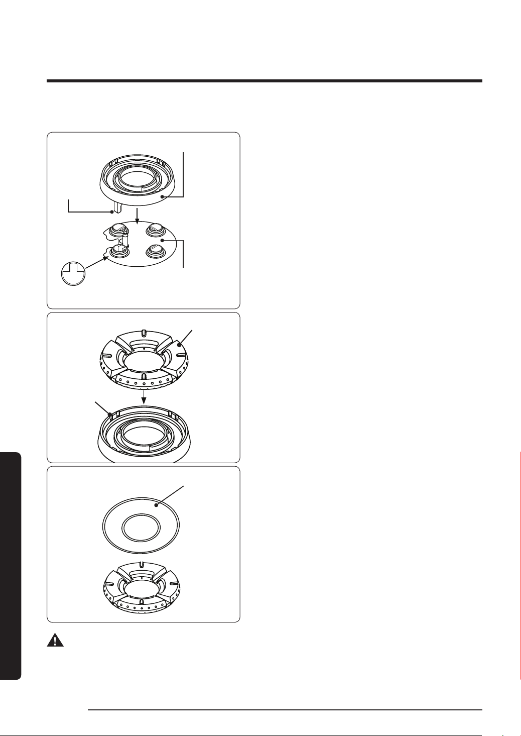
SimmerSear Burner Assembly (18K BTU Burner)
Burner head
Locating
tab
Burner base
Keyed hole
1. Put the burner heads in place as shown
below. The locating tab on the burner
head goes in the keyed hole as shown.
Tabs
Slots
Ridge on bottom of burner cap
Installation instructions
Burner ring
2. Put the burner rings on the burner
heads as shown below. Match the tabs
on the bottom of the ring to the slots
on the burner head. Twist each ring
back and forth slightly to make sure it
is properly seated.
3. Put the burner caps on top of the
burner rings. You may use either the
supplied brass or porcelain caps. The
ridge around the bottom edge of the
cap goes around the top of the burner
ring.
WARNING
Be sure electrical power is off and all surfaces are cool before cleaning any part of the
cooktop.
English58
Page 59

Installing the grates
NOTE
For best results and longest life, install the grates as instructed below. When installed
properly, the openings in the grates are centered over the burners.
The grates occupy specific positions on the rangetop. For maximum stability and safe
operation, these grates should only be used in their proper positions.
The back of the right grate is notched to help orient the grates correctly. (See the graphic
below.)
To correctly position the grates:
1. Find the notch on the back of the right-hand grate, and orient the grate properly
above the right-hand burners.
2. Gently lower the right-hand grate so its legs rest in the corresponding dimples on the
cooktop.
3. Likewise place the remaining grates so their feet rest in the corresponding dimples.
NOTE
Grates are not interchangeable. Each grate has own engraving under it. It tells you which
the front side of grate is and proper position, left, center or right.
English 59
Installation instructions
Page 60

Installation instructions
Verifying proper operation
Before operating the range, read the accompanying use and care manual completely. It
contains Important safety, service and warranty information.
1. Before beginning the test procedure, ensure that all cooktop control valves are in the
OFF position, and all burner rings, burner caps, and grates are properly positioned on
the cooktop frame.
2. Turn on the gas supply at the shut-off valve. Check for gas leaks.
3. Turn on power to the range at the circuit breaker or fuse box.
4. Follow the prompts on the oven’s display to set up the user preferences and wireless
network settings.
5. Touch the MENU key on the display.
6. Touch the BAKE key on the display. The default bake temperature should appear on
the display .
7. Touch Start. After 3 minutes, open the door to make sure the air inside oven has begun
to heat.
8. The display should show BAKE, and the preheating temperature.
9. Touch OFF to stop oven heating process.
10. Test one of the burners by pushing the knob in and turning it counterclockwise to
the HIGH position. It may take up to four seconds for ignition to occur, at which time
the ignitor will stop sparking. If ignition does not occur within four seconds, turn off
the knob, wait for at least five minutes to allow any gas to dissipate, then repeat the
ignition test. After ignition, rotate the control knob counterclockwise from HIGH to
LOW to adjust the flame height progressively. When the range is installed properly,
the flame will be steady and quiet. It will also have a sharp, blue inner cone that will
vary in length proportional to the burner size.
Installation instructions
11. Turn the control knob to the OFF position.
12. Repeat the ignition test for all remaining burners.
Normal Flame
English60
Page 61

If the range does not operate properly, follow these troubleshooting steps:
1. Verify that power and gas are supplied to the range.
2. Check the electrical connections and gas supply to ensure that the installation has
been completed correctly.
3. Repeat the above bake test or burner ignition test.
4. If the appliance still does not work, contact Dacor Distinctive Service at (800) 793-
0093 ex. 2822. Do not attempt to repair the appliance yourself. Have the model and
serial numbers available when you call. See page 7 for location.
Dacor is not responsible for the cost of correcting problems caused by a faulty installation.
English 61
Installation instructions
Page 62

Installation instructions
This page left blank
intentionally
Installation instructions
English62
Page 63

Removal and Re-installation
Removing the Range for Service
1. Turn the gas supply valve to the off position.
2. Turn off power to the range at the circuit breaker panel or fuse box.
3. Pull the range out from the wall
Reinstalling the Range After Service
1. Push the range into operating position, making sure the anti tip bracket is engaged
(see page 51).
2. Turn on power to the range at the circuit breaker panel or fuse box.
3. Turn the gas supply valve to the on position.
English 63
Installation instructions
Page 64

Installation instructions
Installation checklist
WARNING
• To ensure a safe and proper installation, the following checklist should be completed
by the installer to ensure that no part of the installation has been overlooked.
• Proper installation is the responsibility of the homeowner. The importance of proper
installation of your Dacor range cannot be overemphasized.
- Has the plastic coating been peeled off the outside of the range? Have all packaging
materials been removed from inside the oven?
- Are all leveling legs extended down to make contact with the floor? Is the unit
level? See page 51.
- Is the range secured in place with the provided anti-tip bracket and foot according
to these instructions? See pages 34 and 51.
- Is the range wired and grounded according to these instructions and in accordance
with all applicable electrical codes? Has the electrical access cover been replaced?
See pages 33 and 41 to 48.
- Has the gas supply inlet pressure been measured to ensure that it does not exceed
the maximums stated in these instructions. See page 31.
- Is the range connected to the gas supply according to these instructions and in
accordance with all applicable codes? Did the installer check the gas supply for
leaks? Has the gas regulator cover been re-installed? See page 31.
- Is the oven door properly installed according to these instructions? See page 16.
- Have the burner knobs been installed in the proper locations? See page 52.
- Are the burners and grates properly installed according to these instructions? See
page 55.
- Has proper operation been verified? Has the warranty been activated on-line or the
warranty card been filled out completely and mailed?
Installation instructions
English64
Page 65

MEMO
Page 66

MEMO
Page 67

Please visit www.Dacor.com to activate your warranty online.
WARRANTY INFORMATION
IMPORTANT:
Your warranty will not begin until you activate it online or return this form to Dacor. If you have purchased more
than one Dacor product, please return all forms in one envelope, or activate the warranty for each product online.
Please rest assured that under no conditions will Dacor sell your name or any of the information on this form for
mailing list purposes. We are very grateful that you have chosen Dacor products for your home and we do not
consider the sale of such information to be a proper way of expressing our gratitude!
Owner’s Name:
Street:
City: State: Zip:
Purchase Date: Email: Telephone:
Dealer:
City: State: Zip:
Your willingness to take a few seconds to fill in the section below will be sincerely appreciated. Thank you.
1. How were you first exposed to Dacor products? (Please check one only.)
A. T.V. Cooking Show F Builder
B. Magazine G. Architect/Designer
C. Appliance Dealer Showroom H. Another Dacor Owner
D. Kitchen Dealer Showroom I. Model Home
E. Home Show J. Other
2. Where did you buy your Dacor appliances?
A. Appliance Dealer D. Builder
B. Kitchen Dealer E. Other
C. Builder Supplier
3. For what purpose was the product purchased?
A. Replacement
B. Part of a Remodel D. Other
4. What is your household income?
A. Under $75,000 D. $150,000 – $200,000
B. $75,000 – $100,000 E. $200,000 – $250,000
C. $100,000 – $150,000 F. Over $250,000
Last (Please Print or Type) First Middle
only
C. New Home
5. What are the brands of appliances that you have in your kitchen?
A. Cooktop C. Dishwasher
B. Oven D. Refrigerator
6. Would you buy or recommend another Dacor product?
cut herecut here
Thank you very much for your assistance. The information you
have provided will be extremely valuable in helping us plan for the
future and giving you the support you deserve.
Website: www.Dacor.com
Phone: 1+800+793-0093
Yes No
Comments:
Place Serial Number Label Here
Page 68

Dacor ∙ 14425 Clark Avenue, City of Industry, CA 91745 ∙ Phone: (800) 793-0093 ∙ Fax: (626) 403-3130 ∙ www.dacor.com
DG68-00936A-00
 Loading...