

Page 1
Installation Instructions
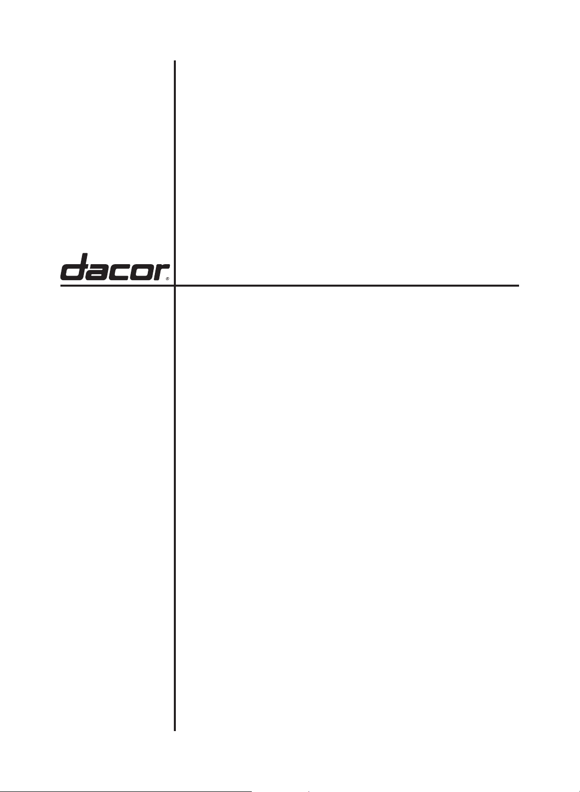
Modernist Built-In Electric Wall Oven
DOB30M977
Part No. 112174 Rev D
Page 2

Contents
Before you begin...
Important
Customer-service info
If You Need Help...
Important safety instructions
Related equipment safety
Transport
I
nstallation requirements
Location requirements
Installation materials
Single ovens—
Product Dimensions
Double ovens—Product Dimensions
3
3
3
3
4
4
4
6
6
7
8
11
Inst
allat
ion
instructions
Preparing to install the oven
Removing and replacing the oven door(s)
Electrical connection
Installing the oven
Installation checklist
Self-diagnosis
15
15
15
18
21
22
23
English2
Page 3
Before you begin...
Important
Design/accessories vary with the model.
Customer-service info
Installer
• For safety and to minimize problems,
read this manual thoroughly before
starting the installation.
• Leave this manual with the user.
• Write the oven’s model/serial
numbers in this manual for service/
maintenance reference.
User
• Keep this manual for personal and
professional reference.
If You Need Help...
To resolve installation issues, contact your
Dacor® dealer or Dacor Customer Assurance.
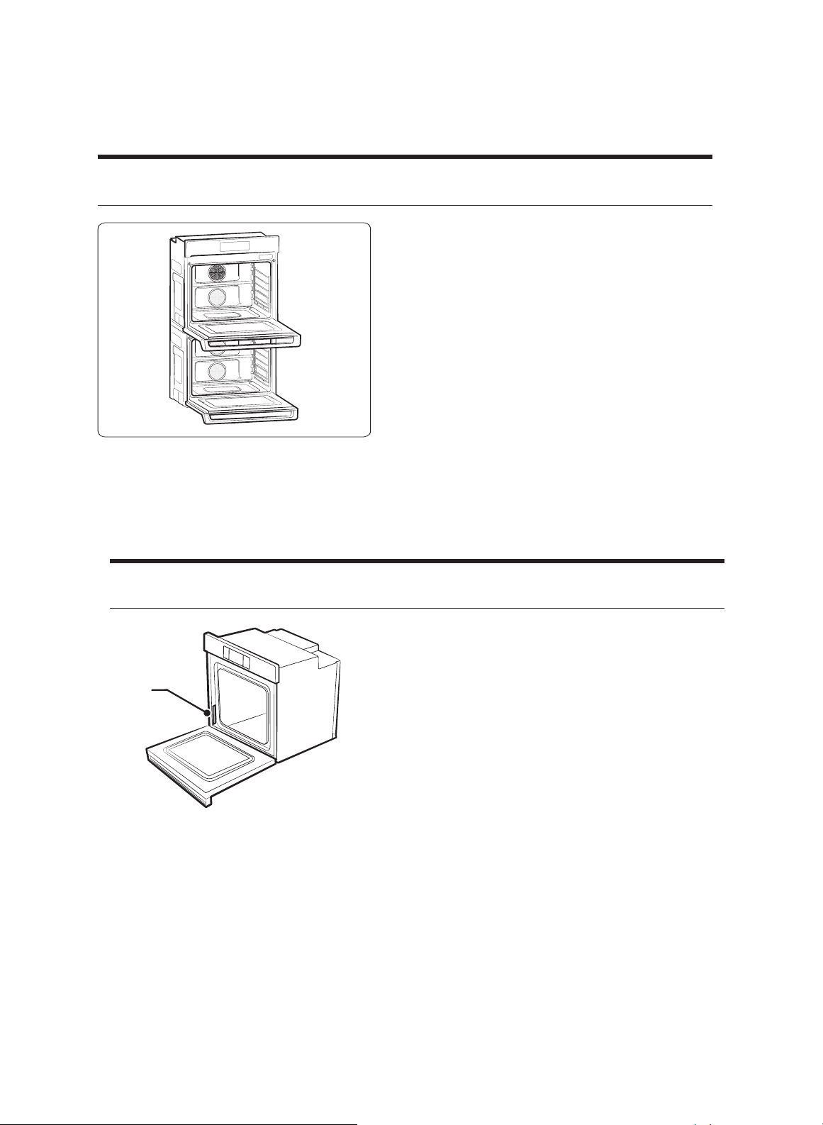
Have the oven model/serial numbers
Rating
Plate
Dacor Customer Assurance
(800) 793-0093 x2813 (USA, Canada)
Mon – Fri, 5:00 a.m. to 5:00 p.m. Pacific Time
Website: www.dacor.com/customer-care/contact-us
All specifications are subject to change without notice. Dacor assumes no liability for suchchanges.
© 2017 Dacor. All rights reserved.
when you call. This information is on the
rating plate on the lower-left door trim. (For
double ovens, the plate is on the lower oven.)
ready
English 3
Page 4
Important safety instructions
Related equipment safety
Remove all tape and packaging before using the oven, and dispose of the packaging.
Never let children play with packaging material.
Do not modify the oven (e.g., do not remove panels, wire covers, or screws).
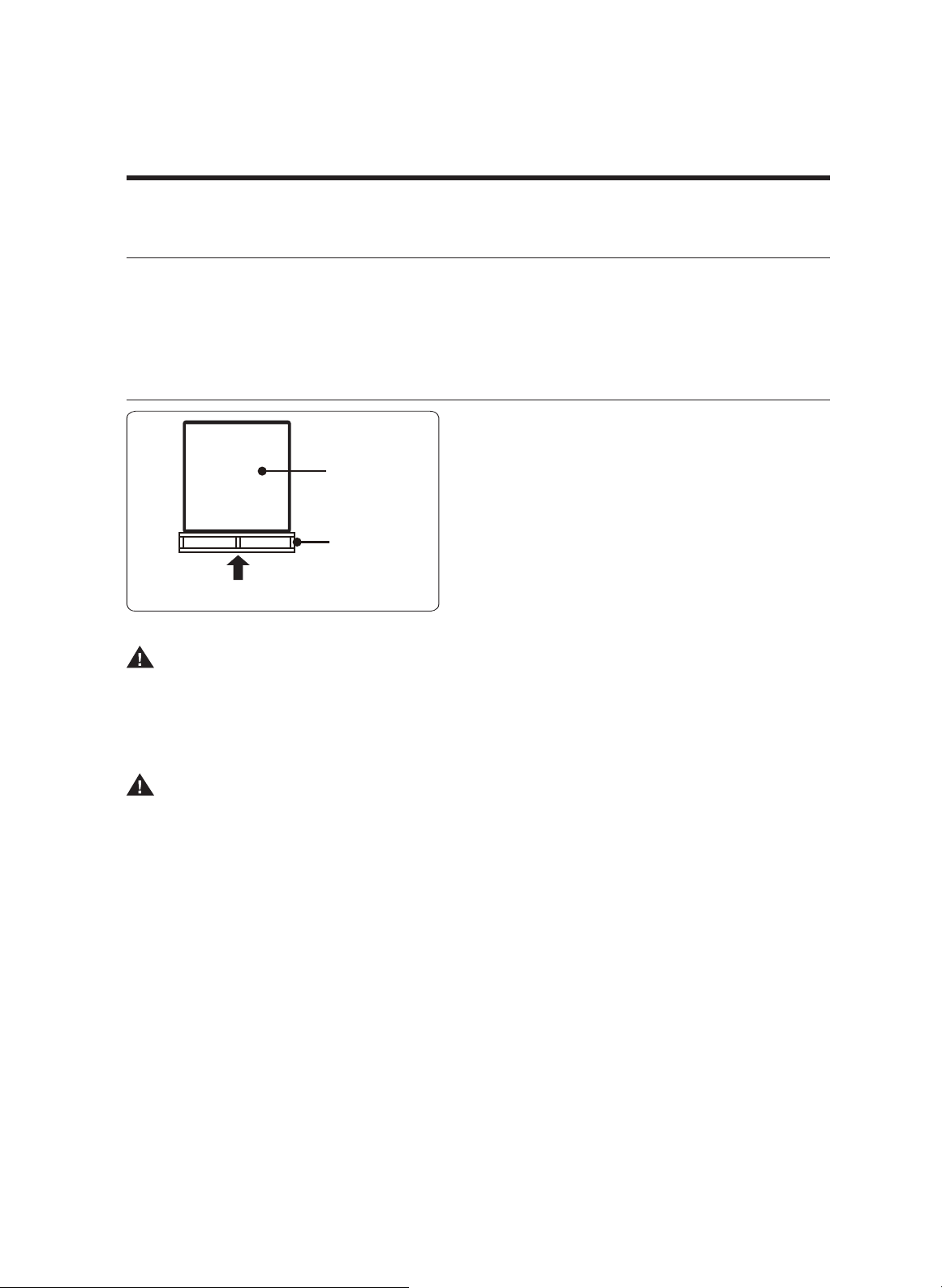
Transport
To avoid damaging the oven vent, use
the transport method shown at left.
Oven (side)
Lift/support the oven bottom from
either side, and move it to the
installation site.
Pallet
Leave the oven attached to the pallet
until it is ready to be lifted into place.
Pallet jack here
DANGER
ELECTRICAL SHOCK HAZARD
To avoid electrical shock, personal injury, or death, verify your appliance is grounded
according to local codes or, in their absence, with the National Electrical Code (NEC).
ANSI/NFPA 70-latest edition.
WARNING
MOVING HAZARD
To avoid severe personal injury, handle/move the oven with two or more people. Using
an appliance-moving device is recommended.
English4
Page 5
Important safety instructions
WARNING
• Follow the information in this manual precisely to avoid fire or electrical shock that
may cause property damage, personal injury, or death.
• Ensure
• New branch-circuit installations (1996 NEC), mobile homes, RVs, or installations
where local codes prohibit grounding through the neutral conductor, require 4-wire
branch-circuit connection.
• Improper connection of aluminum house wiring to copper leads can cause an
electrical/fire hazard. Use only connectors designed for joining copper to aluminum,
and follow the manufacturer’s recommended procedure.
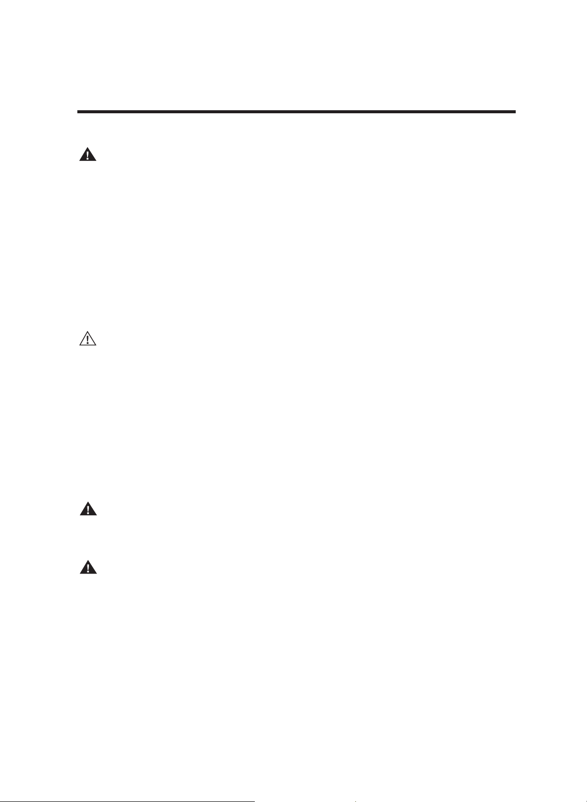
• Mounting screws must be used to secure the oven so it cannot be shifted/dislodged.
CAUTION
• The cabinets and wall coverings around the oven must be able to withstand the heat
[up to 194 °F (90 °C)] generated by the oven.
• Do NOT remove the spacers from the oven's left/right sides. The spacers center the
oven in the cabinet cutout so heat does not build up in one area and damage the
cabinetry or cause a fire hazard.
the oven is properly installed and grounded by a qualified technician.
IMPORTANT NOTE
The installer shall ensure proper installation. The warranty does NOT cover product
failure due to improper installation.
WARNING
Do NOT put weight on the oven door or let anyone climb, sit, stand, or hang on it. The
door could break free, causing personal injury and property damage.
WARNING
The electricity must be off while the electrical connections are made. If not, severe
personal injury or death may occur.
IMPORTANT NOTE
• Observe all governing ordinances.
• Properly ground the oven.
• Do not block oven vents (bottom-front of the oven) or leave combustible or
heat-sensitive items in front of them.
English 5
Page 6

Installation requirements
Location requirements
IMPORTANT: Observe all governing ordinances.
• Specified c
• The cabinet recess must completely enclose all but the face of the oven.
• A grounded electrical supply is required. (See Electrical Requirements.)
• Put the electrical-supply junction box at most 3” (7.6 cm) below the support platform.
• Drill a 1” (2.5 cm) min. diameter hole in the right-/left-rear corner of the support
platform for conduit access to the junction box.
NOTE
For under-counter installation, the junction box should be in the adjacent right/left
cabinet. For rear-wall installation, the junction box should be recessed in the upperright corner of the cutout.
• The support platform must be solid, level, and flush with bottom of cabinet cutout.
• Single oven: The floor must support 221 lb (100 Kg).
• Install the oven at least 12” (30 cm) from other appliances.
utout dimensions are minimums and must be used.
IMPORTANT: Verify with your builder or cabinet supplier that the materials used will not
discolor, delaminate, or
sustain other damage. This oven complies with UL and CSA
International requirements, and the max. allowable wood-cabinet temp. of 194 °F (90 °C).
English6
Page 7
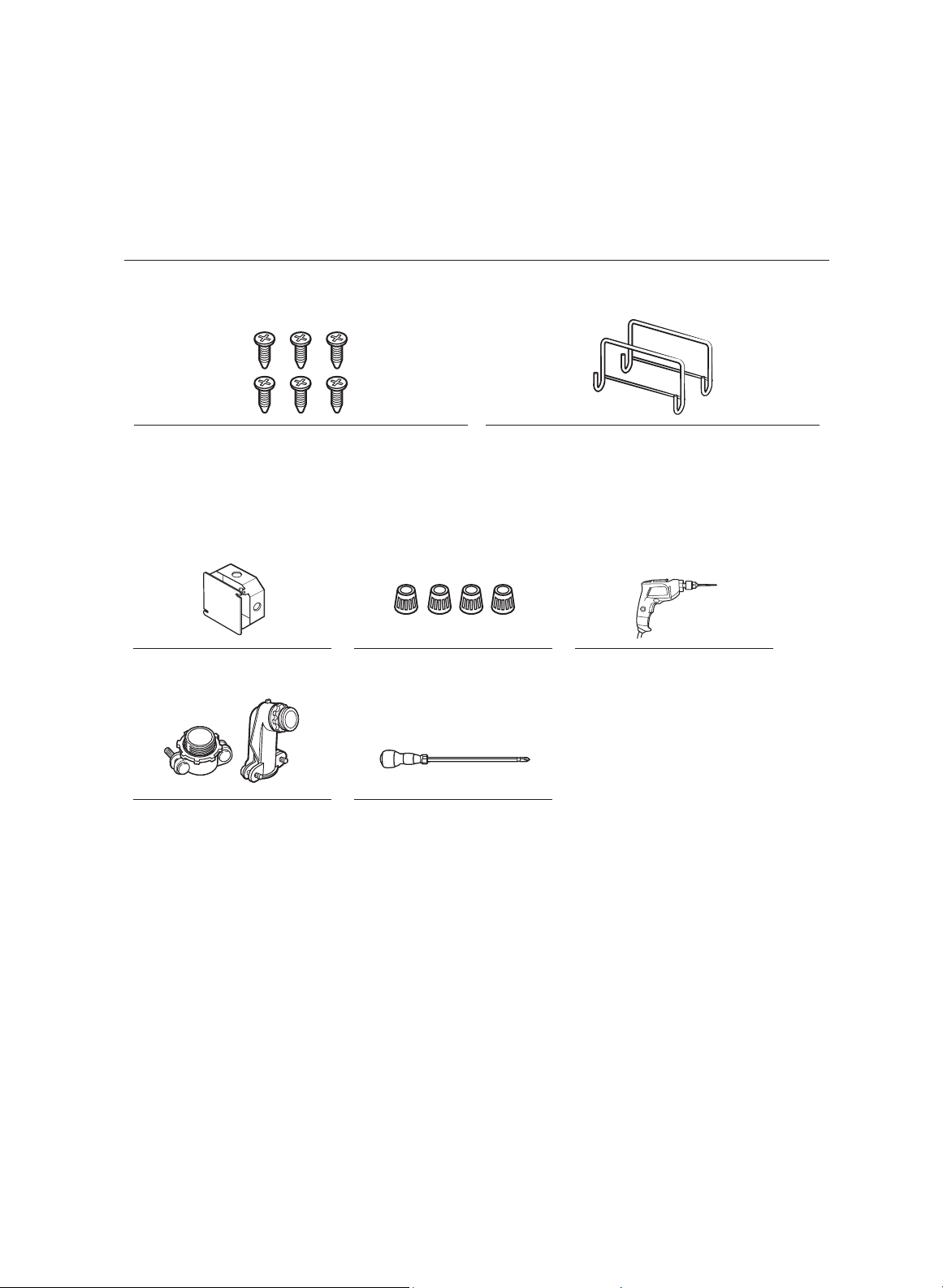
Installation Materials
Provided items
6 screws (M4 L16)
(4 needed for installation, 2 extra)
Needed Items
Junction Box Wire Nuts
3
/4” Conduit Connector
Install Handle (only for double oven)
Drill
Phillips Screwdriver
English 7
Page 8
Installation requirements
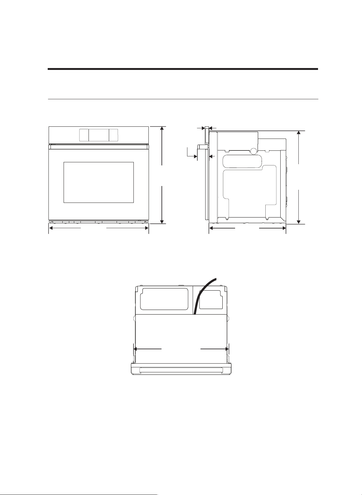
Single ovens—Product Dimensions
31⁄2”
(89 mm)
13⁄8” (33 mm)
287⁄8”
(731 mm)
297⁄8”
(757 mm)
Front Side
281/2”
(724 mm)
(587 mm)
471⁄
4
” (1200 mm)
Conduit length
271⁄4”
(691 mm)
231⁄8”
Top
English8
Page 9

Standard cabinet dimensions
• Dimensions are minimums (except electrical supply location E)
• Allow at least 22” between the open oven door and opposing cabinetry, walls, etc.
• Leave at least 1” clearance under
oven and 1-3/8 in. from cutout opening to
cabinet above or countertop.
• (Flush-mount only)
Leave at least 2 1/2” unobstructed space below oven.
231⁄2”
mm)(597
Top
271/4”
(692 mm)
13/8” (34.9 mm)
Max. 91⁄2" (241
283/4”
(730.25 mm)
FrontSide
mm
)
Min. 22”
(559 mm)
English 9
Page 10

Installation requirements
Flush-cabinet dimensions
• Dimensions are minimums (except electrical supply location E)
• Allow at least 22” between the open oven door and opposing cabinetry, walls, etc.
• Leave at least 1” clearance under oven and 1-3/8 in. from cutout opening to
cabinet above or countertop.
• (Flush-mount only) Leave at least 2 1/2” unobstructed space below oven.
7
24
231⁄2”
mm)
(
597
13⁄8” (33 mm)
(630 mm)
⁄8”
Tasseau
291/8”
(739.77 mm)
1 1/8”
(29 mm)
Top
Max. 91⁄2”
(241 mm)
301⁄4” (767 mm)
283/4” (730.25 mm)
3/4” (19.05 mm) Tasseau
FrontSide
Min. 22”
(559 mm)
English10
Page 11

Double ovens—Product dimensions
13⁄8” (33 mm)
511⁄2”
(1307 mm)
297⁄8” (757 mm) 231⁄8” (587 mm)
Front Side
31⁄2”
(89 mm)
67” (1700 mm)
Conduit length
50”
(1267 mm)
281/2”
(724 mm)
Top
English 11
Page 12

Standard cabinet dimensions
• Dimensions are minimums (except electrical supply location E)
• Allow at least 22” between th
• Leave at least 1” clearance under oven and 1-3/8 in. from cutout opening to
cabinet above or countertop.
• (Flush-mount only) Leave at least 2 1/2” unobstructed space below oven.
e open oven door and opposing cabinetry, walls, etc.
231⁄2”
(597 mm)
11/4” (31.75 mm)
Top
12 English
501/4”
(1276 mm)
12”
(305 mm)
Max. 91⁄2”
(241 mm)
283/4”
(730.3 mm)
FrontSide
Min. 47”
(1194 mm)
Page 13

Installation requirements
Flush-cabinet dimensions
• Dimensions are minimums (except electrical supply location E)
• Allow at least 22” between th
• Leave at least 1” clearance under oven and 1-3/8 in. from cutout opening to
cabinet above or countertop.
• (Flush-mount only) Leave at least 2 1/2” unobstructed space below ove
e open oven door and opposing cabinetry, walls, etc.
n.
Cleat
231⁄
mm)
(
597
13⁄8” (33 mm)
51 3/4”
(1314.5 mm)
2”
247⁄8”
mm)(630
Max. 91⁄2”
(241 mm)
301⁄4” (767 mm)
283/4” (730.25 mm)
Top
Min. 47”
(1194 mm)
3/4” (19.05 mm) Cleat
13⁄8” (33 mm)
3
mm)
⁄4” (1.9
notch
Side Front
12”
(305 mm)
3
⁄
4” (1.9
mm)
notch
English 13
Page 14

If codes permit and a separate ground wire is used, a qualified electrician should verify
that the ground path and wire gauge comply with local codes. Check with a qualified
electrician if you are unsure of the oven's grounding status. This oven must connect to
a grounded-metal, permanent wiring system.
Verify that the electrical connection and wire size are adequate and comply with the
Nat'l Electrical Code, ANSI/NFPA 70-latest edition or CSA Standards C22.1-94, Canadian
Electrical Code, Part 1 and C22.2 No. O-M91-latest edition, and all local regulations.
A copy of these standards can be obtained from:
National Fire Protection
Association 1 Batterymarch
Park Quincy, MA 02169-7471
Electrical Connection
OR
CSA International
85
01 E Pleasant Valley Rd
Cleveland, OH 44131-5575
To properly install the oven, determine the type of electrical connection you will use,
and follow the directions in this manual.
• The oven must connect to the
proper voltage and frequency per
the rating plate. (See pg. 4 for the
plate's location.)
••A circuit breaker is recommended.
Use the chart at right to decide
the minimum recommended
dedicated circuit protection:
KW Rating
(240 V)
≤4.8 KW ≤4.1 KW 20 Amp
4.9 KW - 7.5 KW 4.3 KW - 6.2 KW 30 Amp
7.3 KW - 9.6 KW 6.3 KW - 8.3 KW 40 Amp
9.7 KW - 12.0 KW 8.4 KW - 10.4 KW 50 Amp
KW Rating
(208 V)
Circuit Size
(Dedicated)
• Connect directly to the circuit-breaker box (or fused disconnect) via flexible, armored,
or non-metallic, sheathed, copper cable with ground wire.
• Connect the oven's flexible conduit directly to the junction box.
• Fuse both sides of the line.
• The conduit length must so the oven can be serviced without detaching
the conduit.
• A UL-listed or CSA-approved conduit connector must be provided.
• If the house has aluminum wiring:
– Connect a section of solid copper wire to the ends of the flexible conduit leads.
– Connect the aluminum wiring to the added section of copper wire using special
connectors and/or tools designed and UL listed for joining copper to aluminum.
Follow the electrical-connector manufacturer’s recommended procedure. Copper/
aluminum connecti
Power requirements for
models DOB30M977S
and DOB30M977D:
*and associated models.
14 English
on must comply with local codes and accepted wiring practices.
Model
DOB30M977S
DOB30M977D
11.2 kW 50 Amp 8.4 kW 50 Amp
240 VAC 208 VAC
Power Circuit size Power Circuit size
5.6 kW 30 Amp 4.2 kW 30 Amp
Page 15

Installation instructions
Preparing to install the oven
WA
RNING
Excessive Weight Hazard
To avoid pe
1. Decide the oven's final location. Avoid drilling/cutting household wiring/plumbing.
2. To avoid floor damage, set the oven on a cardboard sheet. (Do not lift by the door
handle or any part of the front frame.)
3. Reduce the oven's weight to ease installation:
a. Remove packing material and tape from the oven.
b. Remove racks and other accessories from the oven chamber.
c. Remove the oven door(s) (see below).
4. Keep any packing material (e.g., corner posts) that may aid the installation.
5. Remove the hardware from the literature pack.
6. Slide the oven (with cardboard beneath) to its installation site.
rson
al in
jury an
d property damage, use two or more people to move the oven.
Removing and replacing the oven door(s)
Removing the oven door(s) before lifting the ov
and will lessen the risk of damaging th
• Remove the door(s) with both hands.
• Before removing a door, arrange a blanket (or the corner posts from the packing
material) on a flat, stable surface on which you will lay the door(s).
Disconnecting the LED wire harness
Find the harness, and disconnect it before removing the door.
Single Double
e door(s) or injuring personnel.
Wire Harness
en into its cutout will make lifting easier
English 15
Page 16

Removing the oven door(s)
Unlocked
Locked
1. Carefully pull out the wire to reveal
the connector.
2. Uncouple the connector.
Open the oven door fully flat.
1.
2.
Find the door hinge locks in both
corners of the door, and flip them
down to the unlocked position (see
left) so the door can be removed.
16 English
3. Partially close the door to engage the
door hinge locks. (The door stops at
this point.)
4. Grasp each side of the door, and
pull it away from the oven. (You
may need to wiggle the door sideto-side as you pull.)
5. Rest the door(s), handle-down, on
the prepared surface.
Page 17

Installation instructions
Replacing the oven door(s)
CAUTION
If needed, get help lifting the door into the hinge slots. Do not lift the door by the handle.
1. Grasping each side at the midpoint, lift
the door, and face the oven.
Slot
2. With the door at a 45° angle, align the
hinges with the slots in the lower front
of the oven.
3. Slowly insert the hinges into the slots.
(You will know the hinges are engaged
when you feel the door drop slightly.)
4. Open the oven door fully flat.
(If the door does not open a full 90°,
repeat Steps 1 – 3.)
5. Flip the hinge locks up to the locked
position. (See pg. 22.)
6. Close the oven door.
(If the gap between the door and
control panel is wider on one side, the
hinge on that side is improperly set.)
7. Connect the wire harness.
English 17
Page 18

Electrical connection
WARNING
Electrical Shock Hazard
• Disconnect power before servicing.
• Use 8-gauge solid copper wire.
• Ground the oven.
• Failure to follow these instructions can result in fire, electrical shock, or death.
This oven is manufactured with a neutral (white) power-supply wire and a cabinetconnected ground (green or bare) wire twisted together.
1. Disconnect power.
2. Feed the oven's conduit through the
UL-listed or
CSA-
approved
conduit
connector
opening in the cabinet.
3. Remove the junction-box cover.
4. Install a UL-listed or CSA-approved
conduit connector on the junction box.
5. Route the oven conduit through the
connector into the junction box.
6. Tighten the conduit connector screws.
7. See the Electrical Connection Options
Chart to complete installation for your
type of electrical connection.
Electrical Connection Options Chart
If your home has: Go to section:
4-wire
3-wire
18 English
4-Wire Cable from Home Power Supply
1/2"
1.3 cm
3-Wire Cable from Home Power Supply
1/2"
1.3 cm
Page 19

Installation instructions
4-Wire Cable from Home Power Supply
IMPORTANT: Use the 4-wire cable from home power supply in:
• the US where local codes do not allow grounding through neutral
• New Branch circuit installations (1996 NEC)
• mobile homes and recreational vehicles
• new construction
• Canada.
A
B
C
D
A. Cable from home power supply
B. Black wires (normally L1)
C. Red wires (normally L2)
D. 4-wire flexible conduit from oven
E. Junction box
F. White wires (normally N-neutral)
G. UL-listed wire connectors
H. Green wires (normally G-ground)
I. UL listed or CSA approved conduit connector
E
F
G
H
I
NOTE: Connect all wires with UL-listed wire
connectors (G).
1.
Con nect the 2 black wires (B).
2.
Connect the 2 red wires (C).
3.
Untwist the white wire from the green
(or bare) ground wire from the oven.
4.
Connect the 2 white wires (F).
5.
Connect the green (bare) ground wire
(H)
from the oven cable to the green
(bare) ground wire (in the junction box).
6.
Install the junction-box cover.
English
1
9
Page 20

3-Wire Cable from Home Power Supply - U.S. Only
IMPORTANT: Use the 3-wire cable from home power supply where local codes permit a
3-wire connection.
A
B
C
D
E
F
A. Cable from home power supply
B. Junction box
C. Black wires (normally L1)
D. White wires (normally N-neutral)
E. Green wires (normally G-ground)
F. 4-wire flexible conduit from oven
G. Red wires (normally L2)
H. UL-listed wire connectors
I. UL-listed or CSA approved conduit connector
G
H
I
NOTE: Connect all wires with UL-listed
wire connectors (H).
1.
Connect the 2 black wires (C).
2.
Connect the 2 white wires (D) and
the oven's green (bare) ground wire.
Connect the 2 red wires (G).
3.
4. Install the junction box cover.
20 English
Page 21

Installing the oven
1. Using 2 or more people, lift the oven
partially into the cabinet cutout. Hang
the install handle on the side of the
oven. (See left.)
NOTE
Barrier
Install
Handle
Before the next step, remove the install
handle; keep it for future use.
2. Push against the oven's front frame
until the back of the frame contacts
the cabinet face or cleat*.
*Flush installation
WARNING
When inserting the oven, take care not to
damage the barrier beneath the oven.
3. Center the oven side to side.
4.
Remove the tape from the front trims.
5.
Through the holes in the trim aligned
with the holes in the oven frame,
s
ecurely fasten the oven
to the
cabinetry with the supplied screws.
English 21
Page 22

Self-diagnosis
1. After connecting the power, verify that the display works properly.
2. Remove all accessories from the oven chamber.
3. You cannot proceed with self-diagnosis if the oven cavity is hot or the door is
open.(In this case, Hot or door appears on the display.)
4. To start self-diagnosis, press-hold both "hidden keys" for 5 seconds.
• See the table below for each model's hidden keys.
• Self-diagnosis
Model DOB30M977D
takes 4-5 minutes.
Control panel
Hidden Key
UPPER OVEN
OFF
TIMER
SETTINGS
UPPER OVEN + LOWER OVEN
LOWER OVEN
OFF
LIGHT
OPEN/CLOSE
RESERVOIR
Model DOB30M977S
Control panel
Hidden Key
TIMER
SETTINGS
LOCK
SETTINGS + OPEN/CLOSE RESERVOIR
OFF
LIGHT
OPEN/CLOSE
RESERVOIR
5. If there is no error, PASS appears on the display with an alert sound.
6. If there is an error, one of these codes appears on the display with an alert sound.
Model
Error code Remark
Upper Broil H-2
Upper Bake H-1
Feature
Lower Broil H-4
Lower Bake H-3
DOB30M977**
ouble/Single Oven
D
Double Oven Only
7. Should an error occur, contact Dacor Customer Assurance: (800) 793-0093 x2813.
22 English
Page 23

Notes
English 23
Page 24

Dacor ∙ 14425 Clark Avenue, City of Industry, CA 91745 ∙ Phone: (800) 793-0093 ∙ Fax: (626) 403-3130 ∙ www.dacor.com
DG68-00923A-00
 Loading...