

Page 1

Installation Instructions
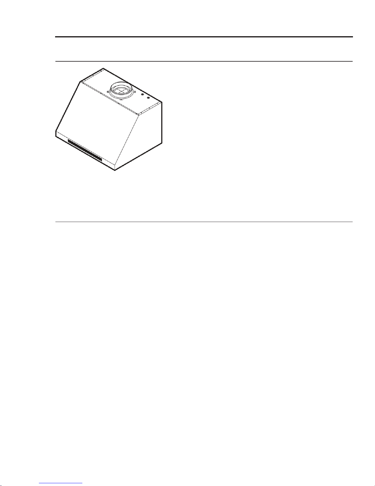
Modernist Range Hood
DHD30M967/DHD36M987/DHD48M987
Part No. 110452 Rev E
Page 2

Contents
Before You Begin
Important Notes
Customer-Assurance Information
Important Safety Instructions
Related Equipment Safety
Installation Safety
Installation Requirements
Checklist
Preparing to Install the Hood
Installation Planning
Hood Specifications
Electrical/Ductwork Connections
Overall Hood Dimensions
Cabinet Layout Dimensions
Installation Instructions
Meeting Electrical Codes
Preparation and Setup
Installing the Electrical Source
Meeting Installation Requirements
Planning th
Planning the Mounting Location
Marking the Exhaust-Duct Centerlines
Installing the Support Brackets
Rotating the Blowers for Rear Exhaust
Assembling the Filters
Using the Optional Dual-to-Single Transition Kit #AHT10
Hanging the Hood
Hardwiring the Hood
Inserting Light Bulbs
Verifying Proper Function
Wiring Diagram
e Ductwork
3
3
3
4
4
4
6
6
6
7
8
9
10
11
12
12
12
13
13
14
16
17
18
19
22
22
23
24
26
26
27
2 English
Page 3
Before You Begin
Important Notes
Installer
• In the interest of safety and to minimize
problems, read this manual thoroughly before
starting the installation.
• Leave this manual with the customer.
• Show the owner how to shut off power to the
hood.
Customer
Keep this manual for personal and professional
reference.
Customer-Assurance Information
To resolve questions and installation issues, contact your Dacor® dealer or Dacor Customer
Assurance. Before calling, have the hood’s model and serial numbers available. (See the data label
inside the hood above the filters on the chassis' rear wall).
Phone: (800) 793-0093 x2813 (US, Canada)
Hours of Operation: Mon – Fri 5:00 a.m. to 5:00 p.m. Pacific Time
Website: www.dacor.com/customer-care/contact-us
All specifications are subject to change without notice. Dacor assumes no liability for such changes.
© 2017 Dacor, all rights reserved.
English 3
Page 4
Important Safety Instructions
Related Equipment Safety
Remove and dispose of all packaging before using the hood. Do not let children play with the
packaging.
Never modify the construction of the hood (e.g., do not remove panels, wire covers, or screws).
DANGER
ELECTRICAL SHOCK HAZARD
To avoid risk of electrical shock, personal injury, or death; ensure the hood is properly grounded
according to local codes or in their absence, with the National Electrical Code (NEC). ANSI/NFPA 70latest edition.
WARNING
MOVING HAZARD
To avoid personal injury, use at least two people to handle the hood. Use an appliance dolly if
possible.
Installation Safety
The Important Safety Instructions and warnings in this manual cannot cover all possible issues.
Use common sense and caution when installing, maintaining, and operating the hood.
Contact Dacor Customer Assurance (Pg. 3) about issues and conditions you do not understand.
WARNING
To reduce risk of property damage, fire, personal injury, and death:
• Do not store or use combustible material (e.g., gas, alcohol, paint thinner, aerosol cans) on
nearby countertops or in adjacent cabinetry.
• Follow the directions in this manual exactly
• Use the hood only as intended by the manufacturer. If you have questions, contact Dacor (Pg. 3).
• Installation and wiring must be done by qualified person(s) according to applicable codes and
standards, including fire-rated construction.
• Sufficient air is needed for proper expulsion of cooktop gases to prevent backdraft; follow the
cooktop manufacturer’s guidelines and safety standards such as those published by the National
Fire Protection Assn (NFPA), and the American Society for Heating, Refrigeration and Air
Conditioning Engineers (ASHRAE), and the local code authorities.
• When cutting or drilling into a wall or ceiling, take care not to damage wiring and other utilities.
• Ducted fans must always be vented to the outdoors.
• Do not use the hood to vent hazardous/explosive materials or vapors. If you have questions,
contact Dacor (Pg. 3).
4 English
Page 5

Important Safety Instructions
Installation Safety, cont.
WARNING
To reduce risk of property damage, fire, personal injury, and death:
• If you receive a damaged product, immediately contact the dealer/builder. Do not install/use a
damaged hood.
•
Install the hood as instructed in this manual and as specified by the cooktop/range manufacturer.
Improper installation, adjustment, alteration can cause serious personal injury or property
damage.
• Do not install/repair/replace any part of the range hood unless specifically instructed in this
manual. A qualified service technician should perform all other service.
• Do not use an extension cord or adapter plug with the hood.
• Do not tamper with the controls.
• Never let the filters become blocked/clogged, or foreign objects (e.g., cigarettes, napkins) be
sucked into the hood.
• Do not use window coverings that could blow over the cooking surface and hood.
• Use only metal ducting.
• The minimum vertical distance between the cooking surface and the lowest part of the hood
must be 30” (76.2 cm). See the instructions in this manual for this distance in your specific case.
• Do not try to operate the hood during a power outage.
• Always turn the hood ON if cooking at high heat or when flaming food.
• Clean ventilating fans frequently so grease does not collect on the filter or other hood parts.
English 5
Page 6

Installation Requirements
Installation Checklist
The installer should review this checklist to verify the thoroughness/accuracy of the installation.
The owner is ultimately responsible for the unit's proper installation.
WARNING
The hood is properly attached to the wall as instructed (Pg. XX).
Ducting is fully installed; joints are secured with sheet-metal screws and wrapped with foil tape
(Pg. 21-23).
The hood is wired/grounded as instructed and per all applicable electric codes (Pgs. 18-19).
Filters are assembled as instructed (Pg. 30).
The setup was verified.
Any problems were noted on the warranty card or during the online warranty activation.
The warranty card was
Preparing to Install the Hood
completed and mailed, or the warranty was activated online.
Have these tools and hardware available before starting the installation.
Hood Installation
• Phillips screwdriver
• Flat-head screwdriver
• Pencil/marking tool
• Wire connector caps
• Wire stripper
• Drill, bits
• Level
• Junction box
• Jigsaw
• 8" ducting
• Foil tape
• Sheet-metal screws
Dual-to-Single Vent Transition Kit (option)
• Dacor Kit #AHT10 (DHD48 only)
• 10" ducts, ducting material
• Drill, bits
• Sheet-metal screws
• Foil tape
Blower Rotation (option)
• Phillips screwdriver
• 5/16" nutdriver
6 English
Page 7

Installation Requirements
Preparing to Install the Hood, cont.
Parts List
Hood (1)
(models vary in size)
Holding brackets, Hardware (2) Dimmable LED light bulbs
Product literature** (2) Dacor cleaning cream (1)
Grease channel (1)
48” (4), 36” (3), 30” (2)
Stainless-steel units only
Baffle-style filter* 48” (4),
36” (3), 30” (2)
Light-replacement tool (1)
* Ready-to-assemble kit
** Installation Instructions, User Manual
Installation Planning
• The owner shall ensure that the hood is installed by qualified personnel.
• The hood should be placed for convenient access. Ensure that electrical power can be provided
to the selected location and that the outlet is easily accessible for service/emergency shutoff
• All minimum clearances must be met. Dimensions shown provide minimum clearances unless
otherwise noted.
• The specified minimum cabinet depth and width must be provided.
• Ensure that you have all tools/materials needed for proper installation before starting.
.
English 7
Page 8
Installation Requirements
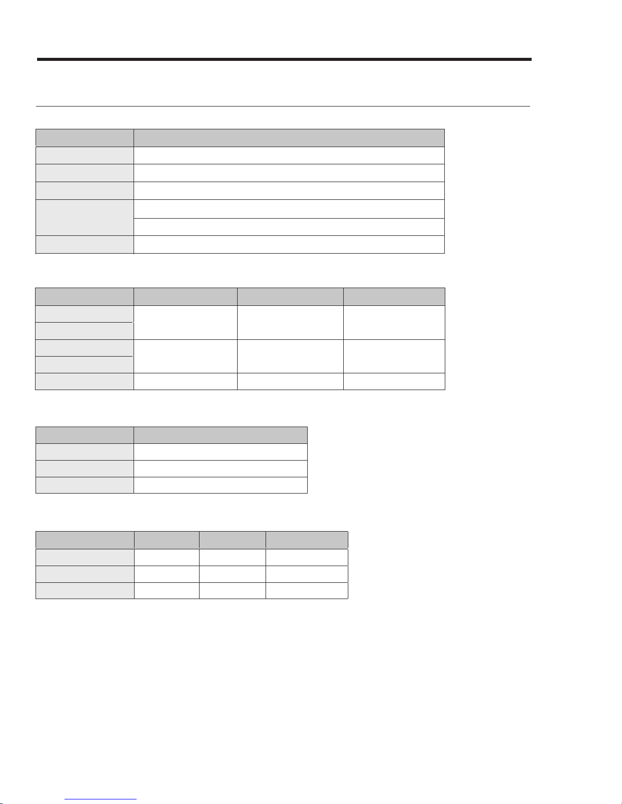
Hood Specifications
General: All Models (DHD30/36/48)
Features Description
Blower Speeds
Filters
Exhaust(s)
Total Connect Load
Lights
Four (4)
Baffle style, dishwasher safe
8” duct diameter
30”, 36”: 120V, 60 Hz, 15 Amp (actual load 3.3 Amp, 6 Amp initial surge)
48”: 120V, 60 Hz, 15 Amp (actual load 6.1 Amp, 12 Amp initial surge)
Dimmable LED: PAR16 E26/27; 120V, 7.5W (75W Max. other bulbs)
General: Individual Models (DHD30/36/48)
Components
Lights
Filters
Blowers
Exhaust Vents
Blower Rating
48” 36” 30”
4 3 2
2 1 1
1200 CFM 600 CFM 600 CFM
Weight: Individual Models (DHD30/36/48)
Model Weight
30
36
48
53 lbs (24 kg)
57 lbs (26 kg)
77 lbs (35 kg)
External Features: Individual Models (DHD30/36/48)
Model Top Vent Rear Vent
30
36
48
x x x
x x x
x x x
8 English
Rotatable Fan
Page 9
Installation Requirements
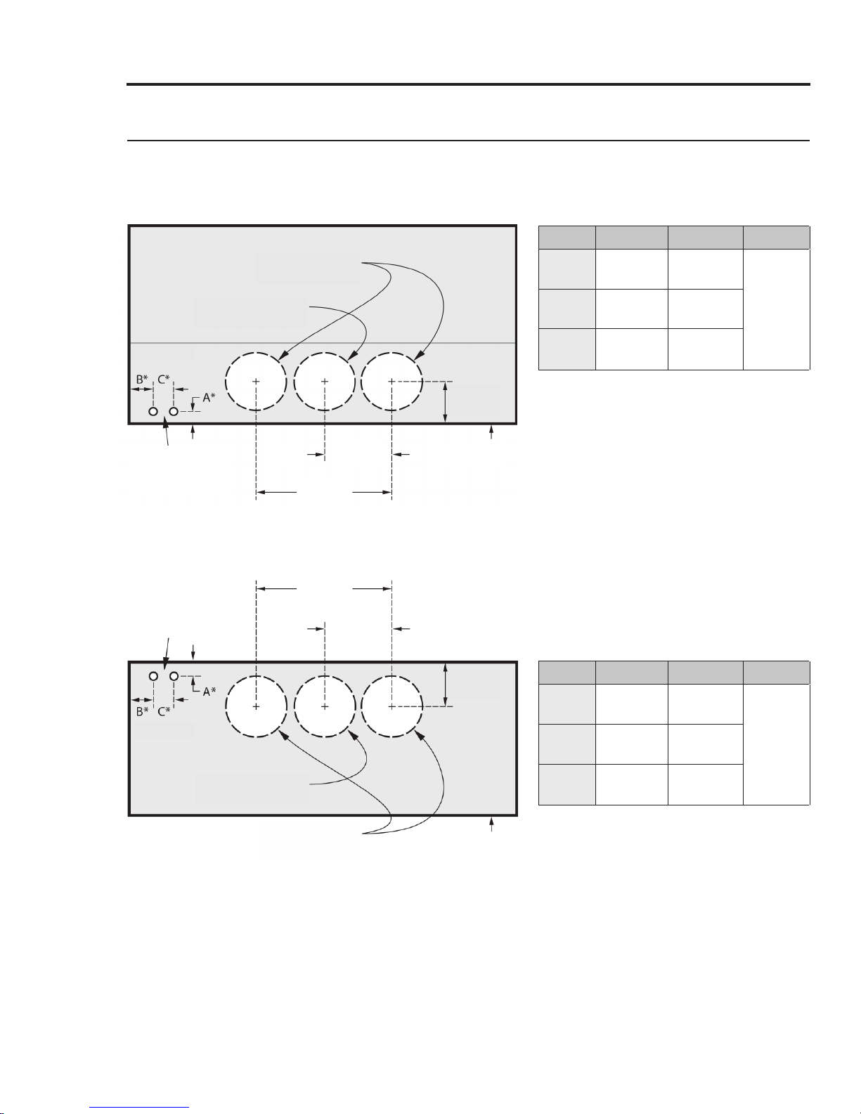
Electrical/Ductwork Connections
Connect wires and ductwork through the top or rear of the hood. Before installing the hood, mark
the access holes according to the diagrams below. (Tolerances: +1/16” -0”, unless otherwise stated.)
Top Connections: All models
Dual-Exhaust
Standard 8" duct
Single-Exhaust
Standard 8" duct
*
See table
7/8 in. (5.1 cm) dia.
Electrical-access
holes (2)
Hood
C/L
19 3/4 in.
(50.2 cm)
Rear Connections: All models
19 3/4 in.
7/8 in. (5.1 cm) dia.
Electrical-access
holes (2)
(50.2 cm)
Hood
C/L
9 7/8 in.
(25.1 cm)
9 7/8 in.
(25.1 cm)
5 3/4 in.
(14.6 cm)
Hood back
(against wall)
Model
48
36
30
A
B C
1 1/2”
(3.81 cm)5”(12.7 cm)
1 1/2”
(3.81 cm)
1 1/2”
(3.81 cm)
4 1/2”
(11.43 cm)
5 1/2”
(14. cm)
3”
(7.62 cm)
*
See table
Single-Exhaust
Standard 8" duct
Dual-Exhaust
Dual-Exhaust
Standard 8" duct
Standard 8" duct
5 3/4 in.
(14.6 cm)
Hood bottom
Model
48
36
30
A
B C
1”
(2.54 cm)5”(12.7 cm)
1”
(2.54 cm)
1”
(2.54 cm)
4 1/2”
(11.43 cm)
5 1/2”
(14. cm)
3”
(7.62 cm)
English 9
Page 10

Installation Requirements
Overall Hood Dimensions
Tolerances: +1/16” -0” unless otherwise stated.
Single Blower DHD30/36 Series
Model
30
36
48
29 7/8” (75.9 cm)
35 7/8” (91.1 cm)
47 7/8” (121.6 cm)
A B C D
Dual Blower DHD48 Series
24”
(61 cm)
18”
(45.7 cm)
12”
(30.5 cm)
10 English
Page 11

Installation Requirements
Cabinet Layout Dimensions
Tolerances: +1/16” -0” unless otherwise stated.
Electrical access
(top and back of
hood)
30" min.
(76.2 cm)
* hood
bottom to
cooking
surface
Min. Width of E (Upper-Cabinet Cutout, Appliance Width)
Model DHD
30
36
48
E
30” (76.2 cm)
36” (91.5 cm)
48” (121.9 cm)
English 11
Page 12

Installation Instructions
Meeting Electrical Codes
• The owner shall verify that all electrical requirements are met by the installer.
• The electrical installation (incl. minimum supply-wire size and grounding) must comply with the
National Electric code ANSI/NFPA (or latest revision), and local codes. Obtain a copy of the
ANSI/NFPA standard from:
National Fire Protection Association
1 Batterymarch Park
Quincy, Massachusetts 02269-9101
• The hood's ground terminal must be connected to a grounded, metallic, permanent wiring
system, or to a grounding conductor installed by a licensed electrician.
• Do not ground the unit or its wiring to a gas pipeline or to the neutral (white) power supply wire.
• Do not install a fuse in the neutral or ground circuit.
• Connect the hood directly to an electrical junction box. Hard-wire the hood per local code
directly to a dedicated, 3-wire, grounded, single-phase circuit rated at 120 Vac 60 Hz, 15 Amp.
WARNING
Electrical Shock Hazard
Ensure a licensed electrician installs the electrical service to the range hood.
Preparation and Setup
This diagram shows the top and rear locations for wire access into the hood.
Top Access
Rear Access
See Wiring Diagrams at the end of this document.
12 English
Page 13

Installation Instructions
Installing the Electrical Source
In compliance with local codes, install an electrical junction box near the hood’s wiring access holes.
Suggested Junction
ox Area
B
Hood
1. In the cabinet or wall, drill 7/8” holes through
which to pass the electrical wiring.
2. See the wiring diagram on the last page of this
manual.
Meeting Installation Requirements
• The hood must be at least as wide as the cooktop.
• All dimensions must fall within specified minimums.
mensions given are minimum clearances unless otherwise noted.
• Di
• All contact points between the hood and cabinetry/walls must be
angles.
• Install th
ood so it can be removed for service.
e h
sturdy, solid, and at righ
t
WARNING
Follow local codes during planning/installation. Contact the local building department for details.
Use only code-approved ductwork.
IMPORTANT: See the diagram on pg. 17 for the minimum installed distance from hood to cooktop
surface. This distance depends on the range or cooktop in use. Check the manufacturer's
specifications for the cooktop or range.
English 13
Page 14

Installation Instructions
Planning the Ductwork
WARNING
• To prevent combustion by-products, smoke, or odors from entering the home, and to improve
efficiency, tape all duct joints securely.
• Range hoods may impede proper flow of smoke and combustion gases from furnaces, gas water
heaters, and fireplaces. To avoid drawing lethal gases into the home, follow the manufacturer’s
directions for these devices and NFPA/ASHRAE recommendations.
• Failure to install a remote blower or proper ductwork may cause a backdraft and insufficient
venting of smoke/fumes.
• DO NOT add an in-line or external blower to lengthen the duct. Even small differences between
blower air-flow rates can greatly reduce the hood’s air draw.
CAUTION
To reduce risk of fire and to properly exhaust air, never duct air into interior spaces.
WARNING
During duct installation, ensure the damper flaps on top of the hood can open freely.
• Building codes may require makeup air systems
A B
to be used with ventilation systems that move air
at greater than the specified rate (CFM), which
rate depends on locale. In designing the system,
consult an HVAC specialist for local requirements
and to ensure best performance.
• All ductwork material (incl. screws and foil tape)
shall be provided by the customer.
• Ductwork must not interfere with floor joists or wall studs.
• On dual-exhaust models, the two 8” exhausts may be merged into one 10” duct using Dacor
Transition Kit AHT10.
• Fasten all joints with sheet-metal screws, and seal with certified duct/foil tape.
• Typically, the blower vents through the hood top (A, above); however, the blower can be rotated
to vent through the rear (B, above). When planning ductwork, always find the shortest, most
direct route to the outside.
Duct-Length Calculation Table
The type of duct determines the hood’s maximum straight duct length. To determine your
maximum length, start with the duct run’s total max. length, then subtract all of the ductwork
equivalent lengths. (See the chart.)
Duct Type Max. Duct Run
8-in. Round
10-in. Round
3 1/4-in x 10-in Rectangular
14 English
60 feet
50 feet
Page 15

Installation Instructions
Planning the Ductwork, cont.
Ductwork Equivalent Lengths
For each new elbow and transition, you must subtract “equivalent lengths” from your total
maximum duct run length to compensate for wind resistance.
Piece Subtract
8” 90° Elbow
8” 45° Elbow
10” 90° Elbow
10” 45° Elbow
3” x 10” to Round 90° Transition
3 1/4” x 10” to 8”/10” Round Transition
Wall Cap w/Damper
Roof Cap
Equivalent lengths of roof and wall caps
vary with model and configuration.
Ductwork Tips
• Try to minimize transitions/turns/sharp angles (e.g., two staggered 45° angles are better than
one sharp 90° angle).
• Keep turns as far from the hood exhaust as possible with as much space between bends as
possible.
• Use round instead of rectangular ducting, especially when elbows are needed.
• If multiple elbows are used, try to keep at least 24 in. of straight duct between each elbow.
• Avoid using “S” or back-to-back adjacent elbows.
• In extremely cold-weather regions, use thermal breaks (i.e., short sections of non-metallic duct)
to avoid indoor heat loss. Put the break as close to the outside pass-through point as possible.
• Do not use flexible metal ducting, or ductwork smaller than what the tables advise.
• The hood exhaust connects to an 8” round duct. You can increase the duct size over the duct run.
• To prevent backdraft, never decrease the duct size over the run. If existing ductwork is under 8"
in diameter, replace it with 8” ductwork.
• Join ducting with sheet-metal screws, then seal with certified duct/foil tape. Never join ducting
with tape only.
• Support the weight of the ducting with sheet-metal screws as needed.
• To avoid backdraft, a damper at the duct outlet may be required.
7 feet
3 feet
5 feet
2 feet
25 feet
4 feet
WARNING
• Electricity to the range hood should be installed only by a licensed electrician.
• Observe all local codes during installation. Consult the local building department as needed.
• Anchor the hood to the wall as instructed to avoid an injury hazard.
• To avoid electric-shock and property damage, do not drill/cut near in-wall plumbing and wiring.
• Use the temporary support brackets only until the hood is permanently anchored.
English 15
Page 16

Installation Instructions
Planning the Mounting Location
Holding brackets and hardware are provided to support the hood so you can permanently anchor it
to the wall.
The illustrations below show the purpose of the holding brackets and the support behind the wall.
• (If mounting the hood to brick or
Adjacent
cabinetry
Bracket
slot (on
hood
back)
Bracket
attached to
wall
Adjacent
cabinetry
masonry) Select anchors rated for the
hood’s weight.
• Properly reinforce the mounting surface
to support the hood’s full weight.
DHD Models Weight
30 53 lbs (24 kg)
36 57 lbs (26 kg)
48 77 lbs (35 kg)
Studs
Mounting
Block
• If mounting the unit to drywall or a
plastered surface, install a reinforced
mounting block between the studs.
• Attach screws directly to the studs and
cabinets if they align with the mounting
holes in the hood back/top.
16 English
Page 17

Installation Instructions
Marking the Exhaust-Duct Centerlines
These measurements/marks help center and level the hood, and mark the duct cutouts. Have a
marking tool, tape measure,
and level ready.
Top-Exhaust
Centerline
Cooktop
1.
Position the hood as it will be when installed (e.g., for a top-vent installation, set the hood with
Rear-Exhaust
Centerline
the vents on top).
2.
Measure the distance from the edge of the hood to the center of the exhaust port.
3.
Transfer that measurement to the wall (for a rear vent), or overhead (for top vent). Measure the
X and Y axes to find the centerline.
4.
Extend the line down 10 inches (25.4 cm).
5.
Cut a hole 1 inch larger than the duct. (Dual-exhaust models require two holes.)
Measurement Location Measurement: in. (cm)
A 9 7/8 in. (25.08 cm)
B 14 1/8 in. (35.88 cm)
C 48 in. (121.92 cm)
D 24 in. (60.96)
E 5 3/4 in. (14.6 cm)
IMPORTANT: For dual-exhaust, you need to install the AHT10 Dual-to-Single Transition Kit. (See the
section Using the Dual-to-Single Transition Kit #AHT10)
English 17
Page 18

Installation Instructions
Installing the Support Brackets
CRITICAL: To avoid alignment issues during final installation, the brackets must not be over/under/
off the centerline.
S
tep 4
Bracket
placement
Hood Area
2 1/8"
Line
indicates
hood top
Mounting bracket
(through wall board) to
mounting block
Mounting block
(attached to studs
inside wall behind
hood)
Stud
1 Marking the Centerlines and Brackets 2 Attaching the Brackets to the Wall
Holding-Bracket Centerline Distance
DHD Models A
30 12 1/2 in (31.8 cm)
36 7 1/8 in (18.1 cm)
48 17 in (43.2 cm)
1. Mark the holding bracket's horizontal centerline 2 1/8" (5.4 cm) below the top of the hood (Image 1). NOTE:
Minimum distance, bottom of cabinets to cooktop: 30" (76.2 cm).
2. Measure and mark the centerline (Image 1) halfway between the cabinets. (If there are no cabinets above
the cooktop, measure and mark the cooktop centerline.)
3. Referring to Image 1 and the above table, measure the "A" distance left and right from the centerline
between the cabinets (or the cooktop centerline), and mark the holding brackets' centerlines.
4. Lay the bracket against the wall, and align the screw holes with the horizontal centerline. (Use anchors/
screws that can support the hood; be sure to properly reinforce the drywall.)
5. Mark the two holes in the bracket.
6. Drill those two holes for screws and anchors.
7. Attach the brackets securely to the wall.
18 English
Page 19

Installation Instructions
Rotating the Blowers for Rear Exhaust
IMPORTANT: Perform this procedure before hang the hood.
WARNING
• Ensure the electrical service meets the hood’s specifications.
• Observe all local codes during installation. Consult the local building department if needed.
• The hood must be installed by a qualified technician with sufficient personnel to assist.
• The owner is ultimately responsible for the hood's proper installation.
Top
Exhaust
Rear
B
Exhaust
The hood comes from the factory in the top-exhaust
configuration (Fig. 1); if you intend to use that
configuration, you do not need to alter the blower’s
position. If, however, the hood will be installed for
rear exhaust, the blowers can be rotated so exhaust
vents out the back (Fig. 2).
Tools Needed
5/16” nut driver
Cable ties
• AHT10 Transition kit (option), metal screws, foil tape
• 10” ducts, ducting material
8” duct and ducting materials
Phillips screwdriver
NOTE: The hood images in this section were chosen to illustrate procedures and may not depict the
hood being installed.
Removing Components
1. Unhook and remove the grease channel.
2. (Taking care not to scratch the hood) Place the
hood assembly on a large, flat surface.
Duct Collar (top of hood)
Back of Hood
3. Remove the duct collar from the hood top.
(Save the collar and screws.)
English 19
Page 20

Installation Instructions
Rotating the Blowers for Rear Exhaust, cont.
Removing Components, cont.
4. Carefully set the hood on its back to access the
bottom.
5. Find the end of the cable assembly plugged into
the bottom left of the blower, then squeeze and
L-Bracket
Blower
Plate
Configuring the Vent L-Brackets
unplug the connector. (To avoid damaging the
cable-assembly contacts and wires, always pull by
the connector.)
6. Unscrew the cable clamp(s), and remove th
hardware that holds the blower and L-bracket.
7. Detach the blower and plate, and set them aside.
e
Back of Hood
Blower/Vent
L-Bracket
Default Blower
Configuration:
Top vent open;
no rear v
ent
Back of Hood
Blower/Vent
L-Bracket
Rotated Blower
Configuration:
Open rear ventNo top vent
1. Unscrew, and remove the L-bracket that is in the default top-venting configuration (left).
2. Turn and align the L-bracket so the hole is in back of the hood (right).
20 English
Page 21

Installation Instructions
Rotating the Blowers for Rear Exhaust, cont.
Re-orienting the Blower(s)
The blower(s) must be correctly positioned.
Left Side
Rear
Blower edge
covers exit
vent
Right Side
Bottom
Blower I/O port
(on right for
rear exhaust)
Hood resting
on its top
Finalizing the Rear-Vent Setup
Front
1.
2.
Standing at the rear of the hood and looking
down at the blower, insert the blower so its I/O
port faces right, and its exhaust port is against the
L-bracket at the rear of the hood.
Set the hood on its top.
Top
Duct collar
1. Refasten the cable clamps and assembly to the
hood.
2. Connect the cable assembly to the blower’s I/O
RightRear
port.
3. Attach the duct collars to the back of the hood.
4. Carefully turn the hood upright.
English 21
Page 22

Installation Instructions
Assembling the Filters
Filters are boxed separately with provided hardware and must be assembled during installation.
B
Knob
Using the Optional Dual-to-Single Transition Kit #AHT10
eveled
p
li
Screw M8
DHD Baffle-Style Filter
Loc
washer
#10
1. Remove the plastic coating, and turn the beveled
lip upward.
2. Align the screw, lock washer, and knob with the
filter. The knob should be on the ridge, and the
screw and lock washer in the trough.
3. Twist-tighten the knob onto each washer/screw.
k
4. Install the filters after hanging the hood.
Replacement Part # Description
702579 Baffle Filter Kit (1 pc + hardware)
702580
Baffle Filter Kit (2 pc + hardware)
2" (5.1 cm)
13 3/4"
(34.9 cm)
3/4"
(1.9 cm)
32"
(81.3 cm)
9" (22.9 cm)
P
reparing the AHT10
Create a lip arou
nd the transition kit by bending the bottom edges outward at right angles, creating
a 3/4” flange around the base.
Bending the Flanges On the Transition Duct
Top/rear vent: Models DHD30/36/48
All four
corners bent
out 90°
On dual-exhaust models, the two 8” duct exhausts
can be transitioned into one 10” duct.
Assemble the Dacor transition kit #AHT10 (sold
separately) before you hang the hood. This
transition kit fits over the top/rear ventilation exits.
22 English
Page 23

Installation Instructions
Using the Optional Dual-to-Single Transition Kit #AHT10, cont.
Installing the AHT10 Transition Kit (top-/rear-vent configuration)
NOTE
The transition kit does not include the sheet-metal screws needed to install the hood.
Top-Vent
Rear-Vent
1. Center the transition kit over the duct collars.
2. Drill screwholes in the flanges, being sure to pierce the hood top.
3. With sheet-metal screws, fasten the AHT10 unit to the hood.
4. With foil tape/duct tape, seal the AHT10 unit’s base.
Hanging the Hood
WARNING
Hanging the range hood requires two people. Do not lift the hood unassisted.
IMPORTANT: Take care not to scratch/damage the hood. Hanging slots in the hood back engage
the holding brackets to support the hood temporarily during installation.
1. Remove the plastic film from the hood.
Adjacent
inetry
cab
2. Lift, and slip the hood onto the holding brackets
through the hanging slots in the hood back.
Bracket
slot (on
hood
back)
Bracket
attached to
wall
Adjacent
cabinetry
3. Adjust the hood into its final posi
4. Mark the spot by drawing in a mounting hole in
the back of the hood. (This is where a screw will
hold the hood to the wall stud or concrete
anchor.)
tion.
English 23
Page 24

Installation Instructions
Hanging the Hood, cont.
Hanging
slots
5. (If needed) Mark the top of the hood if the
configuration calls for the hood to be secured at
the top.
Mounting holes
6. Remove the hood from the wall.
7. Drill the pilot or anchor holes. (If using anchors,
insert them into the anchor holes.)
8. Reset the hood on the holding brackets.
9. Adjust as needed, then anchor the hood.
Hardwiring the Hood
Power may be suppled to the hood through an electrical junction box or a dedicated 15-Amp. circuit
breaker.
WARNING
• Before connecting the wiring, turn OFF power to the hood at the fuse box or circuit breaker.
• Miswiring the hood creates an electric shock or fire hazard and
• Do not ground the wires to the neutral (white) wire. Connect the ground wire to a separate,
properly grounded wire installed by a licensed electrician.
• Use proper-gauge wiring that meets all codes and can accommodate the total connected loads.
may harm its electrical system.
Top Access
Rear Access
24 English
1. Shut power OFF at the circuit breaker or fuse box.
2. Feed the cable assembly through the hood.
Page 25

Installation Instructions
Hardwiring the Hood, cont.
Neutral (white)
Hot (black)
To junction
Box
Grease
Channel
Ground
Screw
Power
Terminals
in Hood
Main Power
Switch Detail
Filter
Wing Nut
Main Power
Switch
N1
L1
Back
Filter
3. With the provided green screw, attach the ground
wire to the ground screw (next to the main power
switch inside the hood above the filters).
IMPORTANT: Use a #10 O-ring at the end of the
ground wire.
4. Remove the wing nut on the main-power-switch
plate, then remove the plate to access the
terminal block and connect the power wires.
5. Insert the white wire and black wire through the
plastic hole protector, and tighten the wires to
their corresponding terminals.
To house circuit
breaker or fusebox
GREEN
GREEN
WHITE
WH
ITE
BLAC
BLAC
Junction box
K
K
Wire nut
(3 places)
Bottom
To range hood
UL/C
SA-approved
NEMA strain relief
6. Connect the hood wiring to an electrical
junction box or circuit breaker.
WARNING
• Do not ground the circuit to a gas line or hot-water pipe.
• Insulated water lines must be jumped to assure continuity to the ground. (See the diagram.)
English 25
Page 26

Installation Instructions
Inserting Light Bulbs
Use only dimmable bulbs. Using non-dimmable bulbs causes damage and faulty operation. If needed,
clean the lens surface so the suction cup will stick to it. Perform this procedure for each hood light.
1. (To avoid a possible short and significant property
Fixture
Dimmable
ulb
B
Suction
Cup
Verifying Proper Function
damage) Shut the main circuit breaker OFF.
2. Attach the suction cup to the bulb lens (both
supplied; see the graphic).
3. Screw the bulb into the light fixture, and remove
the suction cup.
4. Switch the main circuit power ON.
Replacement Part # Description
702666
Dimmable LED Bulb Replacement Kit
(1 bulb + 1 suction-cup tool)
1. Turn OFF the main power switch.
ONOFF
2. Turn power ON at the circuit-breaker panel or
fusebox.
Grease
Channel
Filter
Main Power
Switch Detail/
Hood Bottom
3. Turn ON the main power switch. (The button
panel flashes several times during startup.)
4. (Without scratching the grease channel or other
surfaces) Insert the filters:
a. Set the front edge against the clip, and press.
Main Power
Switch
Front Filter
Clip
Back
Grease
Channel
Filter
b. Lift the rear edge above the grease channel.
c. Set the filter rear edge on the grease channel.
5. On the control panel, press Lights to verify that
all lights turn on.
6. Press Lights to turn the lights to Low, then press
again to turn the lights off.
7. Press POWER to verify that one fan-speed
indicator turns on and the fan is on Low.
Bottom
Lights
8. Press Low/Med/High/Boost to verify that the fan
speed increases each time.
9. Press POWER to turn the fan OFF.
If the Hood Fails to Function Correctly
1. Verify that the hood receives power.
2. Remove the right-most filter to access the main power switch, and confirm the hood is ON.
3. Verify that the electrical connections are correct.
4. Re-run Verifying the Setup.
If the hood still does not work, contact Dacor Customer Assurance (see Pg. 3). Do not make your
own repairs. Dacor will will not pay for serv
ice needed to correct unauthorized repairs.
26 English
Page 27

Installation Instructions
Wiring Diagram
DHD30/36/48
English 27
Page 28

Dacor ∙ 14425 Clark Avenue, City of Industry, CA 91745 ∙ Phone: (800) 793-0093 ∙ Fax: (626) 403-3130 ∙ www.dacor.com
 Loading...