


1 |
Engine and lower engine |
assembly |
10A
11A
12A
13A
14A
16A
17A
17B
19A
19B
19C
ENGINE AND LOWER ENGINE ASSEMBLY TOP AND FRONT OF ENGINE
FUEL MIXTURE
FUEL SUPPLY
ANTIPOLLUTION
STARTING - LOAD
IGNITION
PETROL INJECTION
COOLING SYSTEM
EXHAUST
RESERVOIR
X90
APRIL 2004 |
Edition Anglaise |
"The repair methods given by the manufacturer in this document are based on the technical specifications current when it was prepared.
The methods may be modified as a result of changes introduced by the manufacturer in the
production of the various component units and accessories from which his vehicles are constructed."
All copyrights reserved by Renault.
The reproduction or translation in part of whole of the present document, as well as the use of the spare parts reference numbering system, are prohibited without the prior written consent of Renault.
© Renault s.a.s. 2004

19D ENGINE MOUNTING
X90
APRIL 2004 |
Edition Anglaise |
"The repair methods given by the manufacturer in this document are based on the technical specifications current when it was prepared.
The methods may be modified as a result of changes introduced by the manufacturer in the
production of the various component units and accessories from which his vehicles are constructed."
All copyrights reserved by Renault.
The reproduction or translation in part of whole of the present document, as well as the use of the spare parts reference numbering system, are prohibited without the prior written consent of Renault.
© Renault s.a.s. 2004

L90 - Section 1
Contents
10A ENGINE AND LOWER ENGINE ASSEMBLY
Engine identification |
|
Oil filter |
10A-1 |
Oil consumption |
10A-3 |
Oil pressure |
10A-4 |
Engine/gearbox assembly |
10A-5 |
Sump |
10A-31 |
Oil pump |
10A-41 |
Multifunction support |
10A-43 |
11A |
TOP AND FRONT OF ENGINE |
|
|
Accessories belt |
11A-1 |
|
||
|
Timing belt |
11A-19 |
|
Cylinder head gasket |
11A-29 |
12A |
FUEL MIXTURE |
|
|
Specifications |
12A-1 |
|
||
|
Air inlet |
12A-7 |
|
Air filter: Replacement |
12A-9 |
|
Air filter unit |
12A-11 |
|
Inlet manifold |
12A-13 |
|
Exhaust manifold |
12A-19 |
|
Throttle valve |
12A-23 |
|
Throttle body: Connection |
12A-25 |
13A |
FUEL SUPPLY |
|
|
Petrol supply circuit |
13A-1 |
|
||
|
Injector rail - Injectors |
13A-2 |
|
Fuel pressure |
13A-6 |
|
regulator:Checking |
|
|
Electric fuel: Checking |
13A-7 |
14A |
ANTIPOLLUTION |
|
|
Petrol vapour rebreathing: |
14A-1 |
|
||
|
Operation |
|
|
Fuel vapour rebreathing: |
14A-2 |
|
Checking |
|
|
Fuel vapour canister |
14A-3 |
|
Fuel vapour |
14A-4 |
|
canister:Checking |
16A |
STARTING - LOAD |
|
|
Alternator: General |
16A-1 |
|
||
|
information |
|
|
Alternator |
16A-2 |
|
Starter: Identification |
16A-12 |
|
Starter motor |
16A-13 |
17A |
IGNITION |
|
|
coils |
17A-1 |
|
||
|
Spark plugs |
17A-5 |
Contents
17B |
PETROL INJECTION |
|
|
Location of components |
17B-1 |
|
||
|
Oxygen sensors |
17B-7 |
|
Position and speed sensor |
17B-11 |
|
Fuel supply computer |
17B-13 |
|
Computer: Connection |
17B-19 |
|
Special notes |
17B-21 |
|
Injection warning light |
17B-23 |
|
Immobiliser function |
17B-24 |
|
Injection - air conditioning |
17B-25 |
|
programming |
|
|
Throttle body potentiometer |
17B-26 |
|
Idle speed correction |
17B-28 |
|
Richness regulation |
17B-29 |
|
Central coolant temperature |
17B-30 |
|
management |
|
|
Special notes on the system |
17B-31 |
|
(when driving) |
|
|
Conditions for carrying out |
17B-32 |
|
fault finding (when driving) |
|
|
Combustion misfire fault |
17B-33 |
|
finding |
|
|
Catalytic converter fault |
17B-34 |
|
finding |
|
|
Oxygen sensor fault finding |
17B-35 |
19A |
COOLING SYSTEM |
|
|
General information |
19A-1 |
|
||
|
Specifications |
19A-2 |
|
Checking |
19A-3 |
|
Diagram |
19A-4 |
|
Bleeding and filling the |
19A-6 |
|
cooling circuit. |
|
|
Bleeding the cooling circuit |
19A-8 |
|
Cooling radiator |
19A-9 |
19A |
COOLING SYSTEM |
|
|
Water pump |
19A-14 |
|
||
|
Thermostat |
19A-18 |
|
Engine cooling fan assembly |
19A-19 |
19B |
EXHAUST |
|
|
General information |
19B-1 |
|
||
|
Pipe assembly |
19B-3 |
|
Catalytic converter |
19B-5 |
|
Expansion chamber |
19B-9 |
|
Silencer |
19B-10 |
19C |
RESERVOIR |
|
|
Draining the fuel tank |
19C-1 |
|
||
|
Fuel tank |
19C-3 |
|
Pump / sender unit / filter |
19C-7 |
|
Fuel level sensor: Distinctive |
19C-10 |
19D ENGINE MOUNTING
Suspended engine mounting |
19D-1 |

|
|
ENGINE AND LOWER ENGINE ASSEMBLY |
10A |
|
|
|
Oil filter |
||
|
|
|
|
|
|
|
|
|
|
|
L90, and K7J, and 710 |
|
||
|
|
|
|
|
|
|
Essential special tooling |
|
|
|
|
|
|
|
|
Mot. 1329 |
Oil filter cover - 76 mm |
|
|
|
|
diameter |
|
|
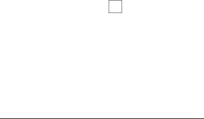
REPLACING THE OIL FILTER |
|
|||
|
|
|
|
|
|
|
|
|
|
109223
Remove the oil filter using tool (Mot. 1329).
Coat the sealing ring of the new oil filter with engine oil.
Tighten the oil filter by hand.
10A-1
|
|
ENGINE AND LOWER ENGINE ASSEMBLY |
10A |
|
|
|
Oil filter |
||
|
|
|
|
|
|
|
|
|
|
|
L90, and K7M, and 710 |
|
||
|
|
|
|
|
|
|
Essential special tooling |
|
|
|
|
|
|
|
|
Mot. 1329 |
Oil filter cover - 76 mm |
|
|
|
|
diameter |
|
|
REPLACING THE OIL FILTER |
|
|||
|
|
|
|
|
|
|
|
|
|
109223
Remove the oil filter using tool (Mot. 1329).
Coat the sealing ring of the new oil filter with engine oil.
Tighten the oil filter by hand.
10A-2
ENGINE AND LOWER ENGINE ASSEMBLY |
10A |
Oil consumption |
L90, and K7J or K7M
PROCEDURE FOR MEASURING OIL
CONSUMPTION
1 - Filling to the maximum level
Note:
The operation should be carried out with the engine warm after the fan assembly has cut in once.
Turn the engine off.
Wait 2 minutes for all the oil to flow into the oil sump.
Carry out a visual inspection using the dipstick.
Top up to the "MAX" mark.
Make a paint mark on both the filler plug and the sump drain plug in order to be able to check later that it has not been removed.
2 - Customer driving
Ask the customer to drive approximately 1240 miles (2000 km) in the vehicle without letting the oil level reach the "MIN" mark.
3 - Topping up
Note:
The operation should be carried out with the engine warm after the fan assembly has cut in once.
Turn the engine off.
Wait 2 minutes for all the oil to flow into the oil sump.
Carry out a visual inspection using the dipstick.
Top up to the "MAX" mark.
Note the quantity of oil added and the mileage covered since the last top-up to maximum level.
4 - Measurement of the oil consumption
Oil consumption = Quantity of topping up oil (in litres) / number of kilometres (in thousands).
10A-3

ENGINE AND LOWER ENGINE ASSEMBLY |
10A |
Oil pressure |
L90, and K7J or K7M
I -CHECKING
Special tooling required
Mot. 36-05 |
Oil pressure gauge kit |
|
|
Ensure that the engine oil level is between the "MIN" and "MAX" marks.
 F
F

 A
A
 B
B


 E
E

 C
C
 D
D

G |
H |
|
87363
Use the tool (Mot. 836-05) and a long dowel of 22 mm.
The oil pressure check must be carried out with the engine warm (approximately 80˚C).
II - USE
K7J |
K7M |
engine |
engine |
|
|
C + E + F
Connect the pressure gauge in place of the oil pressure switch.
III - ENGINE MANAGEMENT
K7J/K7M engine:
- Idling |
: 1 bar |
- 3000 rpm: 3 bar
Torque tighten the oil switch (3.5 daNm).
10A-4
|
ENGINE AND LOWER ENGINE ASSEMBLY |
|
10A |
|||||||||
|
|
Engine/gearbox assembly |
|
|||||||||
|
|
|
|
|
|
|
|
|
|
|
|
|
|
|
|
|
|
|
|
|
|
|
|
|
|
|
L90, and K7J, and 710 |
|
|
|
|
|
|
|
|
|
|
|
|
|
|
|
|
|
|
|
|||||
|
Essential special tooling |
|
|
|
|
|
Tightening torquesm |
|||||
|
|
|
|
|
|
|
|
|||||
|
Mot. 1202-01 |
Clip pliers for cooling |
|
|
shock absorber base |
10,5 daNm |
||||||
|
|
system |
hose |
clips |
|
|
bolts |
|
||||
|
|
(large model) |
|
|
|
|
|
|
|
|||
|
|
|
|
|
brake calliper mounting |
10.5 daNm |
||||||
|
Mot. 1202-02 |
Clip |
pliers |
for cooling |
|
|
||||||
|
|
|
bolts |
|
||||||||
|
|
system |
hose |
clips |
|
|
|
|
|
|
||
|
|
|
|
track rod end nuts |
3.7 daNm |
|||||||
|
|
(small model) |
|
|
|
|||||||
|
|
|
|
|
|
|
|
|
engine tie-bar mounting |
10.5 daNm |
||
|
Mot. 1448 |
Remote |
|
operation |
|
|
||||||
|
|
pliers for cooling sys- |
|
|
bolts |
|
||||||
|
|
tem hose clips |
|
|
|
|
|
|
|
|||
|
|
|
|
|
wheel bolts |
10.5 daNm |
||||||
|
|
|
|
|
|
|
|
|
||||
|
Mot. 1453 |
Multiple-adjusting |
|
|
|
|
|
|
|
|||
|
|
|
|
|
|
|
|
|||||
|
|
engine mounting sup- |
|
|
REMOVAL |
|
||||||
|
|
port |
with |
retaining |
|
|
|
|||||
|
|
straps |
|
|
|
|
|
|
|
|
|
|
|
|
|
|
|
|
|
|
|
||||
|
Mot. 1159-03 |
Engine |
mounting on |
|
|
|
Note: |
|
||||
|
|
right-hand side mem- |
|
|
|
The « engine and gearbox » assembly can be |
||||||
|
|
ber for operations not |
|
|
|
|||||||
|
|
|
|
|
removed by removing the « engine and gearbox/ |
|||||||
|
|
requiring removal of |
|
|
|
|||||||
|
|
|
|
|
driveshafts/half-axles/sub-frame » assembly. |
|||||||
|
|
the engine |
|
|
|
|
|
|||||
|
|
|
|
|
|
|
|
|
|
|||
|
|
|
|
|
|
|
|
|
Place the vehicle on a two-post lift. |
|
||
|
Mot. 1390 |
Support |
for removing |
|
||||||||
|
|
and refitting the engine |
|
|
|
|
|
|
||||
|
|
and gearbox assembly |
|
|
|
IMPORTANT |
|
|||||
|
Tav. 1747 |
Threaded |
rods |
for |
|
|
|
During this operation, use a strap to secure the |
||||
|
|
removing |
the |
sub- |
|
|
|
vehicle to the lift to prevent it from becoming |
||||
|
|
frame |
|
|
|
|
|
|
unbalanced. |
|
||
|
|
|
|
|
|
|
|
|
|
For the strap fitting procedure, (see 02A, Lifting |
||
|
|
|
|
|
|
|
||||||
|
Essential equipment |
|
|
|
|
|
|
equipment, Underbody lift). |
|
|||
|
|
|
|
|
|
|
|
|
|
|
|
|
|
filling station |
|
|
|
|
|
|
|
|
|
|
|
|
|
|
|
|
|
|
|
|
|
|
||
|
|
|
|
|
|
|
|
|
|
|
||
|
Tightening torquesm |
|
|
|
|
|
|
|
|
|
||
|
|
|
|
|
|
|
|
|
|
|
|
|
|
gearbox rubber moun- |
|
|
|
10.5 daNm |
|
|
|
|
|
|
|
|
ting mounting bolts |
|
|
|
|
|
|
|
|
|
|
|
|
gearbox cover moun- |
|
|
|
6.2 daNm |
|
|
|
|
|
|
|
|
ting nut on the gearbox |
|
|
|
|
|
|
|
|
|
|
|
|
rubber mounting |
|
|
|
|
|
|
|
|
|
|
|
|
sub-frame mounting |
|
|
|
10.5 daNm |
|
|
|
|
|
|
|
|
bolts |
|
|
|
|
|
|
|
|
|
|
|
|
|
|
|
|
|
|
|
|
|
|
|
|
|
sub-frame tie-rod upper |
|
|
|
2.1 daNm |
|
|
|
|
|
|
|
|
mounting bolts |
|
|
|
|
|
|
|
|
|
|
|
|
sub-frame tie-rod lower |
|
|
|
6.2 daNm |
|
|
|
|
|
|
|
|
mounting bolts |
|
|
|
|
|
|
|
|
|
|
|
|
steering rack mounting |
|
|
|
10.5 daNm |
|
|
|
|
|
|
|
|
bolts |
|
|
|
|
|
|
|
|
|
|
|
|
|
|
|
|
|
|
|
|
|
|
|
|
|
|
|
|
|
|
|
|
|
|
|
|
|
|
|
|
|
|
|
|
|
|
|
|
|
|
10A-5

ENGINE AND LOWER ENGINE ASSEMBLY |
10A |
Engine/gearbox assembly |
L90, and K7J, and 710
 1
1

 3
3

107846 |
109184 |
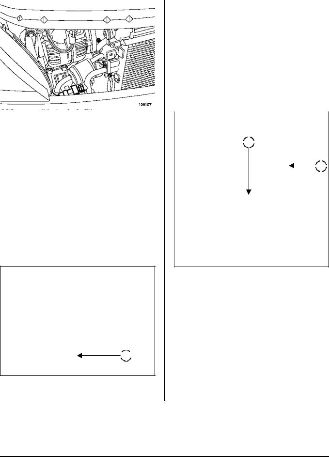
Disconnect the battery, starting with the negative terminal.
Remove:
- fuse and relay cover (1),
- the fuse holders and relays from their supports (2), - battery mounting clamp (3),
- the battery.
2 |
107845
10A-6
ENGINE AND LOWER ENGINE ASSEMBLY |
10A |
Engine/gearbox assembly |
L90, and K7J, and 710
Drain:
- the engine oil if necessary,
- the gearbox oil if necessary,
- the cooling circuit via the bottom hose, using tool (Mot. 1202-01), tool (Mot. 1202-02) or tool (Mot. 1448).
DIRECTION MANUELLE, and BASIC HEATING
 4
4

108564
 7
7 
5 |
 6
6 
109398
Disconnect fan assembly connector (6).
Unclip the electrical harness from fan assembly (7).
108562
Remove:
-the injection computer protector in (4),
-the injection computer in (5),
-the fuse and relay supports,
-the electrolyte recovery tray under the battery,
-the air suction sleeve on the body,
-the front wheels,
-the engine undertray,
-the bumper mounting bolts under the sub-frame.
10A-7
ENGINE AND LOWER ENGINE ASSEMBLY |
10A |
Engine/gearbox assembly |
L90, and K7J, and 710
DIRECTION ASSISTEE, and BASIC HEATING
 9
9 
 8
8

109398
Disconnect fan assembly connector (8).
Unhook the electrical harness from fan assembly (9).
 10
10
 11
11
107924
Remove the power assisted steering pipe mounting bolts:
-from the top of sub-frame (11),
-on the multifunction support,
-on the rear of the cylinder block. Disconnect:
-the low pressure hose on the power assisted steering pump and drain the circuit,
-the high-pressure pipe from the power assisted steering pump,
-the high-pressure pipe from the steering rack.
Remove the power assisted steering high-pressure pipe.
109397
Disconnect connector (10) of the power assisted steering pressure switch.
10A-8

ENGINE AND LOWER ENGINE ASSEMBLY |
10A |
Engine/gearbox assembly |
L90, and K7J, and 710
DIRECTION MANUELLE, and AIR CONDITIONING
12 |
109396
Disconnect fan assembly connectors (12).
 13
13
108107
Disconnect connector (13) from the refrigerant pressure sensor.
Drain the air conditioning circuit using filling station.
Disconnect the air conditioning pipe unions on the air conditioning compressor.
WARNING
Protective plugs must be inserted into the pipe and air conditioning compressor openings to prevent moisture from getting into the circuit.
DIRECTION ASSISTEE, and AIR CONDITIONING
14 |
109396
Disconnect connectors (14) of the fan assembly.
 15
15
109397
Disconnect connector (15) of the power assisted steering pressure switch.
10A-9
|
ENGINE AND LOWER ENGINE ASSEMBLY |
10A |
|||||||||||||||||||||||
|
Engine/gearbox assembly |
||||||||||||||||||||||||
|
|
|
|
|
|
|
|
|
|
|
|
|
|
|
|
|
|
|
|
|
|
|
|
|
|
|
|
|
|
|
|
|
|
|
|
|
|
|
|
|
|
|
|
|
|
|
|
|
|
|
|
|
L90, and K7J, and 710 |
|
|
|
|
|
|
|
|
|
|
|
|
|
|
|
|||||||||
|
|
|
|
|
|
|
|
|
|
|
Drain the air conditioning circuit using the filling sta- |
||||||||||||||
|
|
|
|
|
|
|
|
|
|
|
tion. |
|
|
|
|
|
|
|
|||||||
|
|
|
|
|
|
|
|
|
|
|
Disconnect the air conditioning pipe unions on the air |
||||||||||||||
|
|
|
|
|
|
|
|
|
|
|
conditioning compressor. |
|
|
|
|
|
|
|
|||||||
|
|
|
|
|
|
|
|
|
|
|
|
|
|
|
|
|
|
|
|
|
|
|
|
|
|
|
|
|
|
|
|
|
|
|
|
|
|
WARNING |
|
|
|
|
|
|
|
||||||
|
|
|
|
|
|
|
|
|
|
|
|
Protective plugs must be inserted into the pipe |
|||||||||||||
|
|
|
|
|
|
|
|
|
|
|
|
and air conditioning compressor openings to pre- |
|||||||||||||
|
|
|
|
|
|
|
|
|
|
|
|
vent moisture from getting into the circuit. |
|||||||||||||
|
|
|
|
|
|
|
|
|
|
|
|||||||||||||||
|
|
|
|
|
|
|
|
|
|
|
|
|
|
|
|
|
|
|
|
|
|
|
|
|
|
|
|
|
1 |
|
6 |
|
|
|
|
|
|
|
|
|
|
|
|
|
|
|
|
|
|
||
|
|
|
|
|
|
|
|
|
|
|
|
|
|
|
|
|
|
|
|
|
|||||
|
|
|
|
|
|
|
|
|
|
|
|
|
|
|
|
|
|
|
|
|
|
|
|
|
|
|
|
|
|
|
|
|
|
|
|
|
|
|
|
|
|
|
|
|
|
|
|
|
|
|
|
|
107924 |
|
|
|
|
|
|
|
|
|
|
|
|
|
|
|
|
||||||||
|
Remove the power assisted steering pipe mounting |
|
|
|
|
|
|
|
|
|
|
|
|
|
|
|
|||||||||
|
bolts: |
|
|
|
|
|
|
|
|
|
|
|
|
|
|
|
|||||||||
|
|
|
|
19 |
|
|
|
|
|
|
|
|
|
||||||||||||
|
- from the top of sub-frame (16), |
|
|
|
|
|
|
|
|
|
|
|
|||||||||||||
|
|
|
|
|
|
|
|
|
|
|
|||||||||||||||
|
|
|
|
|
|
|
|
|
|
|
|
|
|
|
|
||||||||||
|
|
|
|
|
|
|
|
|
|
|
|
|
|
|
|
||||||||||
|
- on the multifunction support, |
|
|
|
|
|
|
|
|
|
|
|
|
|
|
|
|||||||||
|
|
|
|
|
|
|
|
|
|
|
|
18 |
|
||||||||||||
|
- on the rear of the cylinder block. |
|
|
|
|
|
|
|
|
|
|
|
|
||||||||||||
|
|
|
|
|
|
|
|
|
|
|
|
||||||||||||||
|
|
|
|
|
|
|
|
|
|
|
|
|
|
|
|
||||||||||
|
|
|
|
|
|
|
|
|
|
|
|
|
|
|
|
||||||||||
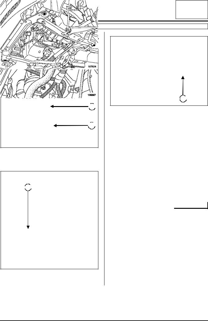
Disconnect:
- the low pressure hose on the power assisted steering pump and drain the circuit,
-the high-pressure pipe from the power assisted steering pump,
-the high-pressure pipe from the steering rack.
Remove the power assisted steering high-pressure pipe.
107356
Disconnect:
- ball joint (18) of the throttle valve control cable,
- cable sleeve stop (19) of the throttle valve control cable.
 17
17
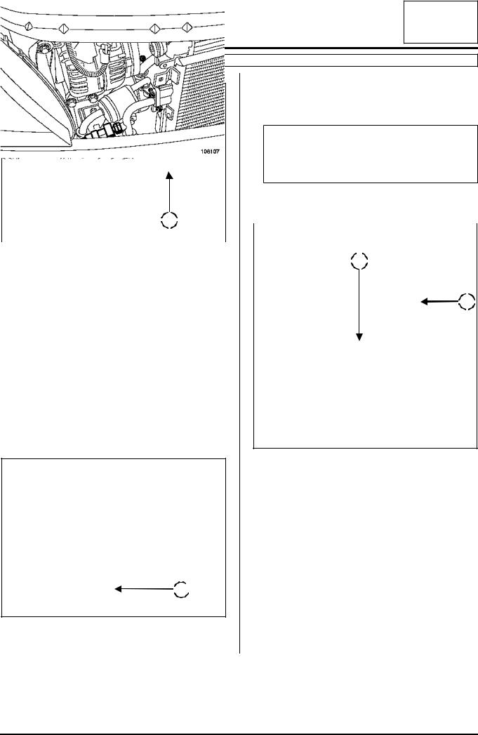
108107
Disconnect connector (17) of the refrigerant pressure sensor.
10A-10
ENGINE AND LOWER ENGINE ASSEMBLY |
10A |
Engine/gearbox assembly |
L90, and K7J, and 710
 20
20
 21
21
107357
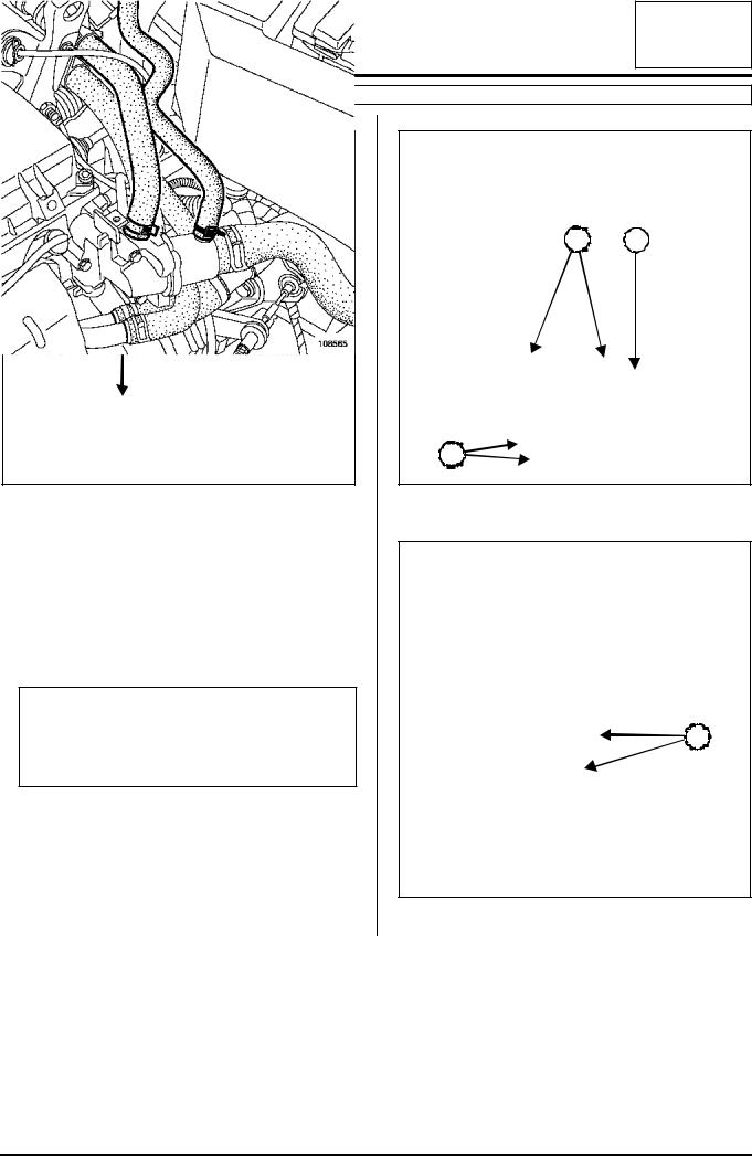
Disconnect:
-the petrol vapour absorber bleeding solenoid valve connector,
-the brake servo pipe from the inlet manifold,
-petrol vapour rebreather pipe (20) from the inlet manifold.
-the fuel supply pipe (21) from the injection rail.
IMPORTANT
Be careful of petrol splashing out when disconnecting the fuel supply union.
Wear gloves during the operation.
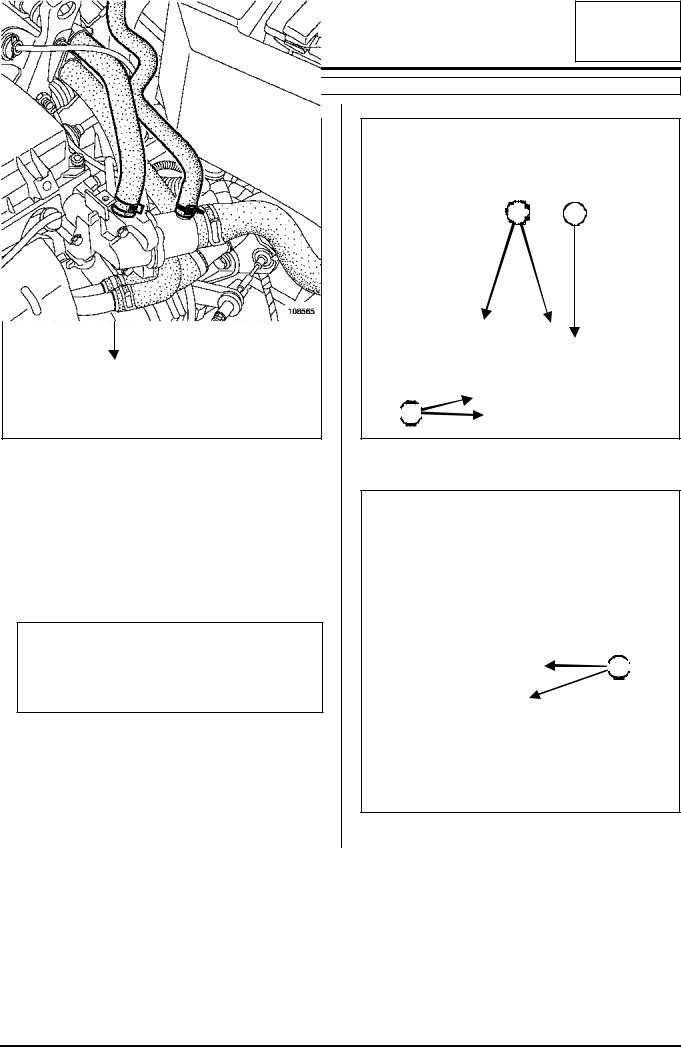
22 |
22 |
22 |
108565
Disconnect cooling hoses (22).
23 |
109493
Remove cooling hoses (23) from their support.
10A-11

ENGINE AND LOWER ENGINE ASSEMBLY |
10A |
Engine/gearbox assembly |
L90, and K7J, and 710
 24
24
107934
Remove mounting bolt (24) from the earth strap on the gearbox.
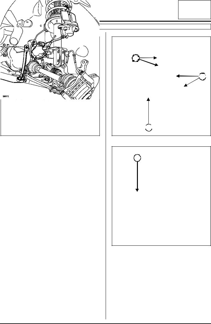
27 |
25 |
|
 26
26
107935
 28
28
99070
Remove:
-brake callipers (25) and attach them to the shock absorbers,
-track rod ends (26),
-bolts (27) from the shock absorber bases,
-upper mounting bolts (28) of the sub-frame tie rods,
-the two mounting bolts from the steering rack. Attach the steering rack to the body.
10A-12
ENGINE AND LOWER ENGINE ASSEMBLY |
10A |
Engine/gearbox assembly |
L90, and K7J, and 710
 29
29
 30
30
109494
Remove:
-the clutch control cable from clutch fork (29),
-the clutch control cable from sleeve stop (30).
 31
31
109213
Remove rubber protection (31) from the gear lever.
 32
32
109214
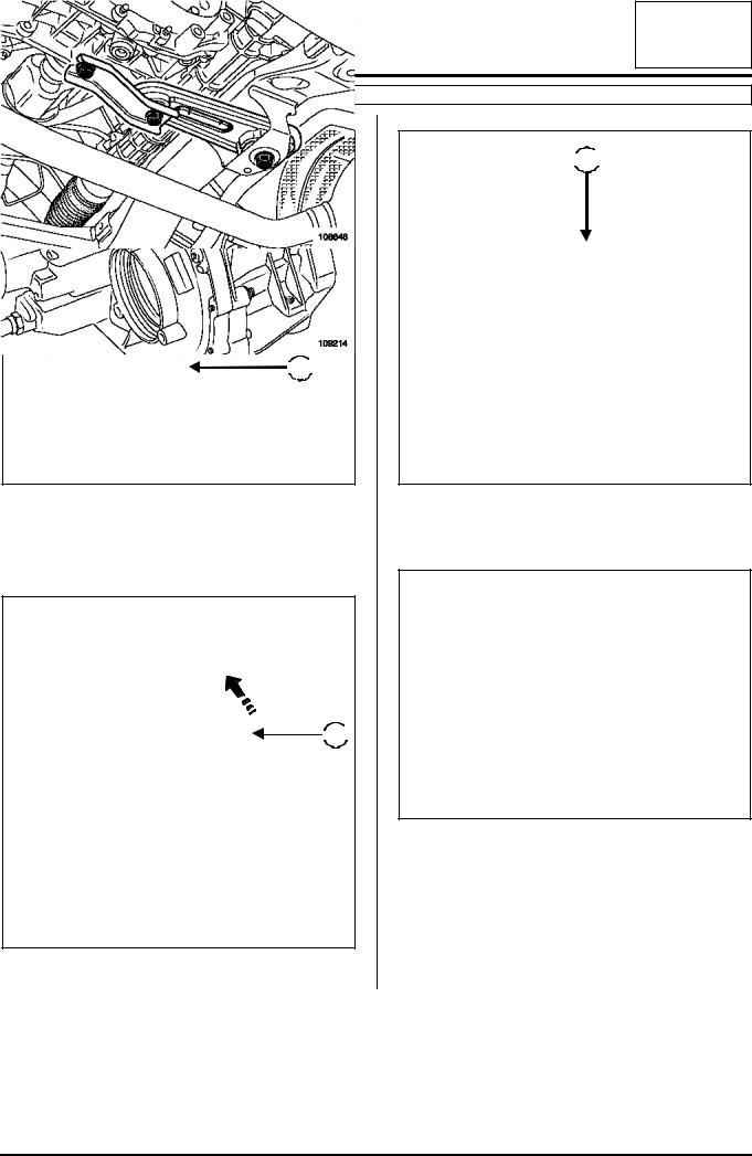
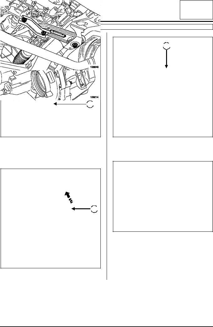
Remove mounting bolt (32) from the gear lever fork. Attach the gearbox control linkage to the body.
108648
Remove the engine tie-bar.
Remove the catalytic converter (see 19B, Exhaust, Catalytic converter).
10A-13
ENGINE AND LOWER ENGINE ASSEMBLY |
10A |
Engine/gearbox assembly |
L90, and K7J, and 710
109495
Fit engine support tool (Mot. 1453) with the retaining belt, by taking the timing end lifting eye as an anchoring point.
33 |
108649
Remove:
-the suspended engine mounting cover mounting bolts,
-the suspended mounting from engine (33).
|
|
|
|
|
|
|
|
|
|
|
|
35 |
|
|
|
|
34 |
||||
|
|
|
|
|
|
|
|
|
|
|
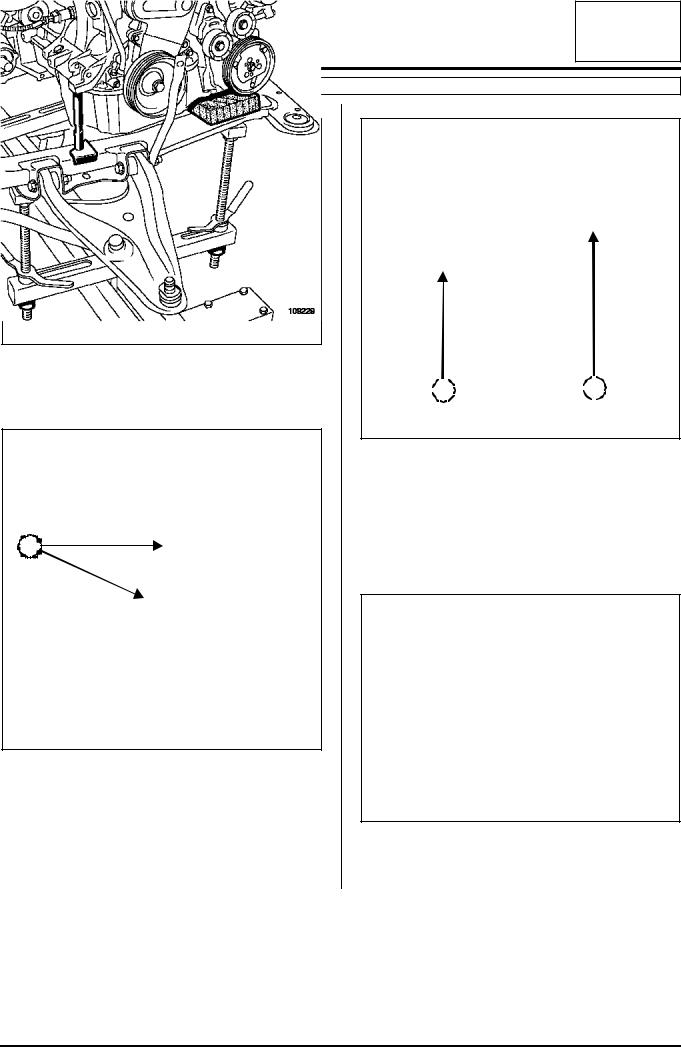
109229
Put a shim under the engine on the right-hand side of the sub-frame:
-put a rubber shim under multifunction support (34),
-fit tool (Mot. 1159-03) to the rear of engine (35),
-lower the engine to fix it in place on the right-hand side of the sub-frame.
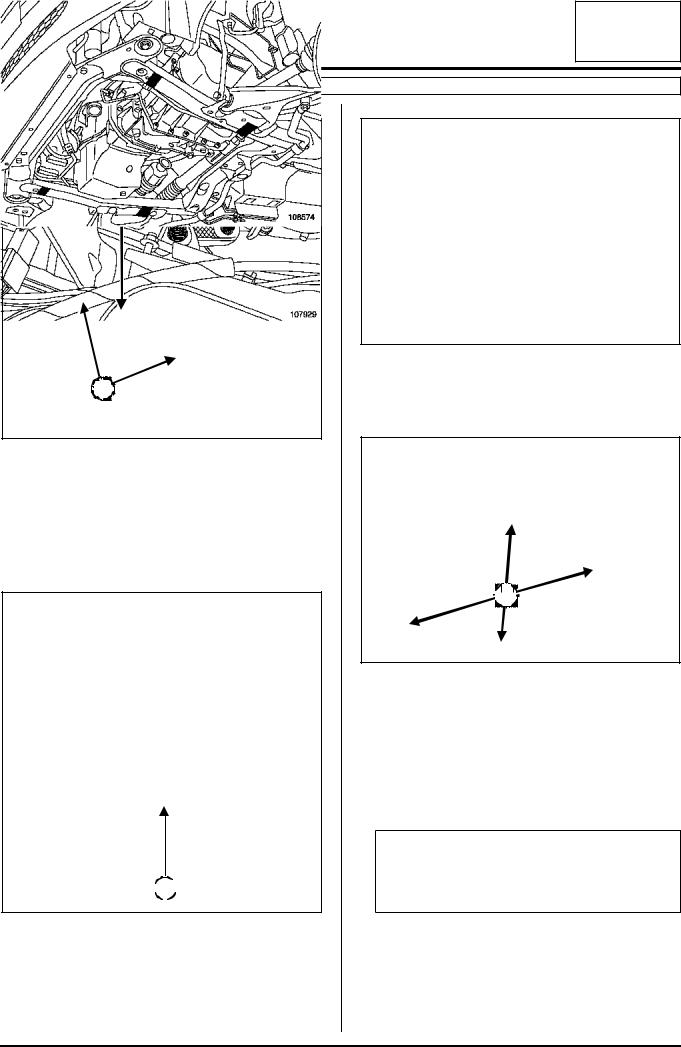
107930
Fit engine support tool (Mot. 1453) with the retaining belt, by taking the flywheel end lifting eye as an anchoring point.
10A-14
ENGINE AND LOWER ENGINE ASSEMBLY |
10A |
Engine/gearbox assembly |
L90, and K7J, and 710
 36
36
37 |
107929
Remove mounting nut (36) of the gearbox cover on the gearbox rubber mounting.
Strike the gearbox mounting stud with a copper hammer to uncouple « engine and gearbox » assembly from the body.
Remove gearbox rubber mounting (37).
 38
38
109230
Put a shim under the gearbox on the left-hand side of the sub-frame:
-put a rubber shim under gearbox (38),
-lower the gearbox to fix it in place on the left-hand side of the sub-frame.
17765
Place tool (Mot. 1390) under the sub-frame.
Lower the vehicle down onto the four pads of tool (Mot. 1390).
39 |
108574
Adjust the pad position to ensure the sub-frame is stable on tool (Mot. 1390).
Bring the pads into contact with the underside of the sub-frame in (39).
Lift the vehicle to separate « engine and gearbox/dri- veshafts/half-axle/sub-frame» assembly from the body.
WARNING
Ensure that no component obstructs the movement of the body around the « engine and gearbox » assembly.
10A-15
|
ENGINE AND LOWER ENGINE ASSEMBLY |
|
10A |
||
|
Engine/gearbox assembly |
|
|||
|
|
|
|
|
|
|
|
|
|
|
|
|
L90, and K7J, and 710 |
|
|
|
|
REFITTING |
Torque tighten: |
|
|||
|
|
|
- the gearbox rubber mounting mounting bolts |
||
|
|
|
|||
|
|
|
(10.5 daNm), |
|
|
|
|
|
- the gearbox cover mounting nut on the gearbox |
||
|
|
|
rubber mounting (6.2 daNm), |
|
|
|
|
|
- the sub-frame mounting bolts (10.5 daNm), |
||
|
|
|
- the sub-frame tie-rod upper mounting bolts (2.1 |
||
|
|
|
daNm), |
|
|
|
|
|
- the sub-frame tie-rod lower mounting bolts (6.2 |
||
|
|
|
daNm), |
|
|
|
|
|
- the steering rack mounting bolts (10.5 daNm) |
||
|
107927 |
|
- the shock absorber base bolts (10,5 daNm), |
||
|
Use two threaded rods of tool (Tav. 1747) on the |
||||
|
sub-frame front mountings to guide the sub-frame |
- the brake calliper mounting bolts (10.5 daNm), |
|||
|
when fitting the « engine and gearbox » assembly. |
||||
|
|
|
|
||
|
|
|
- the track rod end nuts (3.7 daNm), |
||
|
|
|
|||
|
|
|
- the engine tie-bar mounting bolts (10.5 daNm), |
||
|
|
|
- the wheel bolts (10.5 daNm). |
|
|
|
|
|
Refit the catalytic converter (see 19B, Exhaust, Ca- |
||
|
|
|
talytic converter). |
|
|
|
|
|
Perform the following operations: |
|
|
|
|
|
- top up the engine oil if necessary, |
|
|
|
|
|
- top up the gearbox oil if necessary, |
||
|
|
|
- fill up and bleed the cooling circuit (see 19A, Coo- |
||
|
109495 |
|
|||
|
|
|
ling, Draining - Filling the cooling circuit). |
||
|
|
|
|
||
|
|
|
DIRECTION ASSISTEE, and BASIC HEATING |
||
|
|
|
Fill up the power assisted steering circuit. |
||
|
|
|
Bleed the power assisted steering circuit by turning |
||
|
|
|
the steering wheel fully in one direction then the |
||
|
|
|
other with the engine running. |
|
|
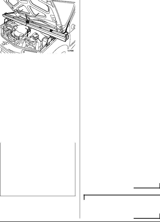
107930 DIRECTION MANUELLE, and AIR CONDITIONING
Use tool (Mot. 1453) to fit the suspended engine
Fill up the air conditioning circuit with filling station.
mounting of the « engine and gearbox » assembly.
Coat the brake calliper mounting bolts with LOCTITE
FRENBLOC.
10A-16
ENGINE AND LOWER ENGINE ASSEMBLY |
10A |
Engine/gearbox assembly |
L90, and K7J, and 710
DIRECTION ASSISTEE, and AIR CONDITIONING
Fill up the power assisted steering circuit.
Bleed the power assisted steering circuit by turning the steering wheel fully in one direction then the other with the engine running.
Fill up the air conditioning circuit with filling station.
Proceed in the reverse order to removal.
WARNING
Connect the battery, starting with the positive terminal; carry out the necessary programming (see
80A, Battery: Remove and Refit).
10A-17
|
ENGINE AND LOWER ENGINE ASSEMBLY |
|
10A |
|||||||||
|
|
Engine/gearbox assembly |
|
|||||||||
|
|
|
|
|
|
|
|
|
|
|
|
|
|
|
|
|
|
|
|
|
|
|
|
|
|
|
L90, and K7M, and 710 |
|
|
|
|
|
|
|
|
|
|
|
|
|
|
|
|
|
|
|
|||||
|
Essential special tooling |
|
|
|
|
|
Tightening torquesm |
|||||
|
|
|
|
|
|
|
|
|||||
|
Mot. 1202-01 |
Clip pliers for cooling |
|
|
shock absorber base |
10.5 daNm |
||||||
|
|
system |
hose |
clips |
|
|
bolts |
|
||||
|
|
(large model) |
|
|
|
|
|
|
|
|||
|
|
|
|
|
brake calliper mounting |
10.5 daNm |
||||||
|
Mot. 1202-02 |
Clip |
pliers |
for cooling |
|
|
||||||
|
|
|
bolts |
|
||||||||
|
|
system |
hose |
clips |
|
|
|
|
|
|
||
|
|
|
|
track rod end nuts |
3.7 daNm |
|||||||
|
|
(small model) |
|
|
|
|||||||
|
|
|
|
|
|
|
|
|
engine tie-bar mounting |
10.5 daNm |
||
|
Mot. 1448 |
Remote |
|
operation |
|
|
||||||
|
|
pliers for cooling sys- |
|
|
bolts |
|
||||||
|
|
tem hose clips |
|
|
|
|
|
|
|
|||
|
|
|
|
|
wheel bolts |
10.5 daNm |
||||||
|
|
|
|
|
|
|
|
|
||||
|
Mot. 1453 |
Multiple-adjusting |
|
|
|
|
|
|
|
|||
|
|
|
|
|
|
|
|
|||||
|
|
engine mounting sup- |
|
|
REMOVAL |
|
||||||
|
|
port |
with |
retaining |
|
|
|
|||||
|
|
straps |
|
|
|
|
|
|
|
|
|
|
|
|
|
|
|
|
|
|
|
||||
|
Mot. 1159-03 |
Engine |
mounting on |
|
|
|
Note: |
|
||||
|
|
right-hand side mem- |
|
|
|
The « engine and gearbox » assembly can be |
||||||
|
|
ber for operations not |
|
|
|
|||||||
|
|
|
|
|
removed by removing the « engine and gearbox/ |
|||||||
|
|
requiring removal of |
|
|
|
|||||||
|
|
|
|
|
driveshafts/half-axle/sub-frame » assembly. |
|||||||
|
|
the engine |
|
|
|
|
|
|||||
|
|
|
|
|
|
|
|
|
|
|||
|
|
|
|
|
|
|
|
|
Place the vehicle on a two-post lift. |
|
||
|
Mot. 1390 |
Support |
for removing |
|
||||||||
|
|
and refitting the engine |
|
|
|
|
|
|
||||
|
|
and gearbox assembly |
|
|
|
IMPORTANT |
|
|||||
|
Tav. 1747 |
Threaded |
rods |
for |
|
|
|
During this operation, secure the vehicle onto the |
||||
|
|
removing |
the |
sub- |
|
|
|
lift with a strap to prevent it from becoming unba- |
||||
|
|
frame |
|
|
|
|
|
|
lanced. |
|
||
|
|
|
|
|
|
|
|
|
|
For the strap fitting procedure, (see 02A, Lifting |
||
|
|
|
|
|
|
|
||||||
|
Essential equipment |
|
|
|
|
|
|
equipment, Underbody lift). |
|
|||
|
|
|
|
|
|
|
|
|
|
|
|
|
|
filling station |
|
|
|
|
|
|
|
|
|
|
|
|
|
|
|
|
|
|
|
|
|
|
||
|
|
|
|
|
|
|
|
|
|
|
||
|
Tightening torquesm |
|
|
|
|
|
|
|
|
|
||
|
|
|
|
|
|
|
|
|
|
|
|
|
|
gearbox rubber moun- |
|
|
|
10.5 daNm |
|
|
|
|
|
|
|
|
ting mounting bolts |
|
|
|
|
|
|
|
|
|
|
|
|
gearbox cover moun- |
|
|
|
6.2 daNm |
|
|
|
|
|
|
|
|
ting nut on the gearbox |
|
|
|
|
|
|
|
|
|
|
|
|
rubber mounting |
|
|
|
|
|
|
|
|
|
|
|
|
sub-frame mounting |
|
|
|
10.5 daNm |
|
|
|
|
|
|
|
|
bolts |
|
|
|
|
|
|
|
|
|
|
|
|
|
|
|
|
|
|
|
|
|
|
|
|
|
sub-frame tie-rod upper |
|
|
|
2.1 daNm |
|
|
|
|
|
|
|
|
mounting bolts |
|
|
|
|
|
|
|
|
|
|
|
|
sub-frame tie-rod lower |
|
|
|
6.2 daNm |
|
|
|
|
|
|
|
|
mounting bolts |
|
|
|
|
|
|
|
|
|
|
|
|
steering rack mounting |
|
|
|
10.5 daNm |
|
|
|
|
|
|
|
|
bolts |
|
|
|
|
|
|
|
|
|
|
|
|
|
|
|
|
|
|
|
|
|
|
|
|
|
|
|
|
|
|
|
|
|
|
|
|
|
|
|
|
|
|
|
|
|
|
|
|
|
|
10A-18
ENGINE AND LOWER ENGINE ASSEMBLY |
10A |
Engine/gearbox assembly |
L90, and K7M, and 710
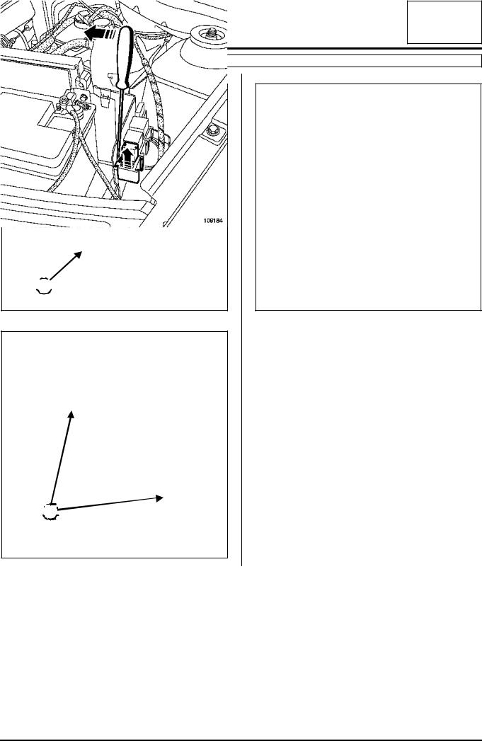
 1
1 
 3
3

107846 |
109184 |
Disconnect the battery, starting with the negative terminal.
Remove:
- fuse and relay cover (1),
- the fuse holders and relays from their supports (2), - battery mounting clamp (3),
- the battery.
 2
2


107845
10A-19
ENGINE AND LOWER ENGINE ASSEMBLY |
10A |
Engine/gearbox assembly |
L90, and K7M, and 710
Drain:
- the engine oil if necessary,
- the gearbox oil if necessary,
- the cooling circuit via the bottom hose, using tool (Mot. 1202-01), tool (Mot. 1202-02) or tool (Mot. 1448).
DIRECTION MANUELLE, and BASIC HEATING
4 |
108564
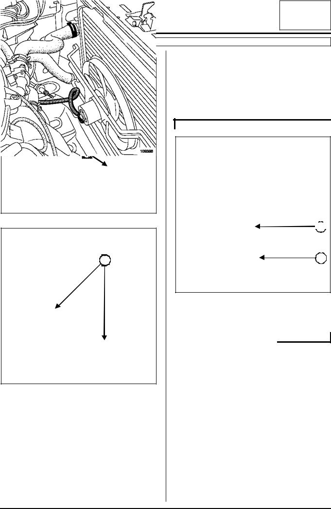
 7
7

5 |
6 |
109398
Disconnect fan assembly connector (6).
Unclip the electrical harness from fan assembly (7).
108562
Remove:
-the injection computer protector in (4),
-the injection computer in (5),
-the fuse and relay supports,
-the electrolyte recovery tray under the battery,
-the air suction sleeve on the body,
-the front wheels,
-the engine undertray,
-the bumper mounting bolts under the sub-frame.
10A-20
ENGINE AND LOWER ENGINE ASSEMBLY |
10A |
Engine/gearbox assembly |
L90, and K7M, and 710
DIRECTION ASSISTEE, and BASIC HEATING
 9
9

 8
8

109398
Disconnect fan assembly connector (8).
Unhook the electrical harness from fan assembly (9).
 10
10
11
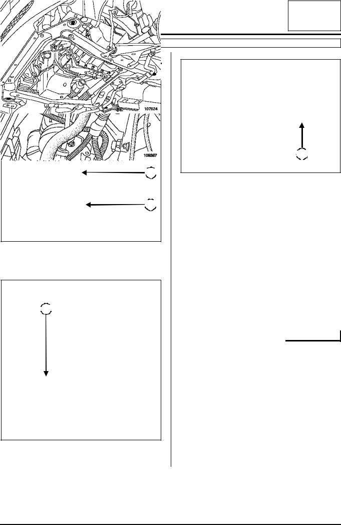
107924
Remove the power assisted steering pipe mounting bolts:
-from the top of sub-frame (11),
-on the multifunction support,
-on the rear of the cylinder block. Disconnect:
-the low pressure hose on the power assisted steering pump and drain the circuit,
-the high-pressure pipe from the power assisted steering pump,
-the high-pressure pipe from the steering rack.
Remove the power assisted steering high-pressure pipe.
109397
Disconnect connector (10) of the power assisted steering pressure switch.
10A-21

ENGINE AND LOWER ENGINE ASSEMBLY |
10A |
Engine/gearbox assembly |
L90, and K7M, and 710
DIRECTION MANUELLE, and AIR CONDITIONING
12 |
109396
Disconnect fan assembly connectors (12).
 13
13
108107
Disconnect connector (13) from the refrigerant pressure sensor.
Drain the air conditioning circuit using filling station.
Disconnect the air conditioning pipe unions on the air conditioning compressor.
WARNING
Protective plugs must be inserted into the pipe and air conditioning compressor openings to prevent moisture from getting into the circuit.
DIRECTION ASSISTEE, and AIR CONDITIONING
14 |
109396
Disconnect fan assembly connectors (14).
 15
15
109397
Disconnect connector (15) of the power assisted steering pressure switch.
10A-22
ENGINE AND LOWER ENGINE ASSEMBLY |
10A |
Engine/gearbox assembly |
L90, and K7M, and 710
Drain the air conditioning circuit using filling station.
Disconnect the air conditioning pipe unions on the air conditioning compressor.
WARNING
Protective plugs must be inserted into the pipe and air conditioning compressor openings to prevent moisture from getting into the circuit.
|
|
|
|
|
|
|
|
|
|
|
|
|
|
|
|
|
|
|
|
|
|
|
|
|
|
|
|
|
|
|
|
|
|
|
|
|
|
|
|
|
|
16 |
|
|
|
|
|
|
|
|
|
|
|
|
|
|
|
||
|
|
|
|
|
|
|
|
|
|
|
|
|
|
|
|
||||
|
|
|
|
|
|
|
|
|
|
|
|
|
|
|
|
|
|
|
|
|
|
|
|
|
|
|
|
|
|
|
|
|
|
|
|||||
107924 |
|
|
|
|
|
|
|
|
|
|
|
|
|||||||
Remove the power assisted steering pipe mounting |
|
19 |
|
|
|
|
|
|
|
|
|||||||||
|
|
|
|
|
|
|
|
|
|||||||||||
bolts: |
|
|
|
|
|
|
|
|
|
|
|
|
|||||||
|
|
|
|
|
|
|
|
|
|
|
|
||||||||
- from the top of sub-frame (16), |
|
|
|
|
|
|
|
|
|
|
|
|
|||||||
- on the multifunction support, |
|
|
18 |
|
|
||||||||||||||
|
|
|
|||||||||||||||||
|
|
|
|
|
|
|
|
|
|
|
|
||||||||
- on the rear of the cylinder block.
Disconnect:
-the low pressure hose on the power assisted steering pump and drain the circuit,
-the high-pressure pipe from the power assisted steering pump,
-the high-pressure pipe from the steering rack.
Remove the power assisted steering high-pressure pipe.
107356
Disconnect:
- ball joint (18) of the throttle valve control cable,
- cable sleeve stop (19) of the throttle valve control cable.
 17
17
108107
Disconnect connector (17) of the refrigerant pressure sensor.
10A-23
ENGINE AND LOWER ENGINE ASSEMBLY |
10A |
Engine/gearbox assembly |
L90, and K7M, and 710
 20
20
 21
21
107357
Disconnect:
-the petrol vapour absorber bleeding solenoid valve connector,
-the brake servo pipe from the inlet manifold,
-petrol vapour rebreather pipe (20) from the inlet manifold,
-fuel supply pipe (21) from the injection rail.
IMPORTANT
Be careful of petrol splashing out when disconnecting the fuel supply union.
Wear gloves during the operation.
22 |
22 |
 22
22


108565
Disconnect the cooling hoses (22).
 23
23

109493
Remove cooling hoses (23) from their support.
10A-24
ENGINE AND LOWER ENGINE ASSEMBLY |
10A |
Engine/gearbox assembly |
L90, and K7M, and 710
 24
24
107934
Remove mounting bolt (24) from the earth strap on the gearbox.
27 |
 25
25

 26
26
107935
28 |
99070
Remove:
-brake callipers (25) and attach them to the shock absorbers,
-track rod ends (26),
-bolts (27) of the shock absorber bases,
-upper mounting bolts (28) of the sub-frame tie rods,
-the two mounting bolts from the steering rack. Attach the steering rack to the body.
10A-25
ENGINE AND LOWER ENGINE ASSEMBLY |
10A |
Engine/gearbox assembly |
L90, and K7M, and 710
 29
29
 30
30
109494
Remove:
-the clutch control cable from clutch fork (29),
-the clutch control cable from sleeve stop (30).
 31
31
109213
Remove rubber protection (31) from the gear lever.
 32
32
109214
Remove mounting bolt (32) from the gear lever fork. Attach the gearbox control linkage to the body.
108648
Remove the engine tie-bar.
Remove the catalytic converter (see 19B, Exhaust, Catalytic converter).
10A-26
 Loading...