


1304 2004
Table of contents
 Loading...
REPAIR MANUAL
vnx.su
DACIA COMMERCIAL
RM 503-1 MECHANICS
ENGINE: F8Q
GERBOX: NG1; NG7
TAPV: U75D; U75E; U75G
Ref: 6001 999 462 NOVEMBER 2004 English version
The reparation methods prescribed by the manufacturer in the present document are established subject to
technical specifications in force at the document issuing date.
These are subject to modifications brought by the manufacturer at the fabrication of different assemblies,
subassemblies or accessories of its vehicles.
All rights reserved to SC Automobile Dacia SA.
Reproduction or translating even partially of this present document is forbidden without the written
authorisation of AUTOMOBILE DACIA S.A.
General poinds vehicle
vnx.su
0
01 SPECIFICATIONS
Engine - Clutch - Gearbox ........................... 01-1
Vehicle identification ................................. 01-2
02 LIFTING
Mobile jack Protection routes ....................... 02-1
Elevator to be attached under the carriage
body .............................................................. 02-2
03 TOWING
All types ........................................................ 03-1
04 LUBRICANTS CONSUMABLES
Conditions ..................................................... 04-1
05 DRAINING AND FILLING
Engine ............................................................ 05-1
Gearbox ......................................................... 05-2
Rear axle differential ..................................... 05-3
07 VALUES AND SETTINGS
Dimensions .................................................... 07-1
Capacity - Qualities .......................................07-10
Wheels and tires............................................ 07-11
Brakes ........................................................... 07-12
Heights under carriage body ......................... 07-13
Control values of the front axle angles ..........07-14
Control values of the rear axle angles ...........07-18
1
Engine and peripherics
10 ENGINE AND LOWER ENGINE UNITS
Ingredients .................................................... 10-1
Idetification ................................................... 10-2
Oil consumption ............................................. 10-3
Oil pressure .................................................... 10-4
Dismounting - Remounting engine ............... 10-5
Engine fitting - unfitting ............................... 10-9
Tightening moments......................................10-10
Characteristics .............................................. 10-11
Necesary special tools .................................. 10-16
Dismounting - Remounting............................ 10-17
Lower crankcase............................................ 10-37
Oil pump........................................................ 10-38
Crankshaft sealing gasket towards
distribution ................................................... 10-39
Crankshaft sealing towards flyweel............... 10-40
Engine set replacing ......................................10-41
11 UPPER AND FRONT ENGINE UNITS
Distribution belt ............................................ 11-1
Cylinder head gasket..................................... 11-4
12 FUEL MIXTURE
Intake manifold............................................. 12-1
Exhaust manifold .......................................... 12-2
13 PUMP SUPPLY
Fuel stop in case of collision....................... 13-1
Characteristics .............................................. 13-2
Particularities................................................ 13-4
Cleanliness rules ......................................... 13-6
Elements location.......................................... 13-8
Operation ................................................... 13-10
Injection indicator operation ........................ 13-12
Anti-starting function.................................... 13-13
Idle running rotation correction.................... 13-14
Pre / Post –heating control........................... 13-15
Injectors ....................................................... 13-17
Decreased flow electric valve and stop
electric valve................................................. 13-18
Increased flow electric valve and advance
electric valve................................................. 13-20
Injection pump connector.............................. 13-22
Injection pump.............................................. 13-24
Injection pump pressing on........................... 13-27
Diesel oil filter.............................................. 13-29
Water temperature centralised control
(G.C.T.A.)..................................................... 13-30
Acceleration potentiometer........................... 13-31
Diagnosis - Generalities................................ 13-32
Diagnosis - damages interpretation .............. 13-34
Diagnosis – Help........................................... 13-66
Diagnosis - Conformity checking................. 13-67
Breakdown localizing algorithm ................. 13-70
14 ANTIPOLLUTION
Oil vapors re-aspiration................................ 14-1
Exhaust gases recycling (E.G.R.) ................. 14-2
16 STARTING AND CHARGING
Alternator ..................................................... 16-1
Starter ........................................................... 16-6
19 COOLING - EXHAUST - FUEL TANK
Characteristics .............................................. 19-1
Draining – Filling – Purging ........................ 19-2
Checking....................................................... 19-3
Cooling system diagram................................ 19-4
Water pump................................................... 19-5
Radiator......................................................... 19-6
Exhaust assembly.......................................... 19-7
Tank draining................................................. 19-9
Dismounting – Remounting tank................... 19-10
Fuel level transmitter..................................... 19-11
Tightening moments (da Nm)........................ 19-12
2
vnx.su
Transmission
20 CLUTCH
Identification................................................. 20-1
Diagnostic .................................................... 20-2
Mechanism - Disk ........................................ 20-5
Engine flywheel............................................ 20-6
Clutch shaft bearing...................................... 20-7
21 MANUAL GEARBOX
Characteristics.............................................. 21-1
Tightening moments in daNm...................... .21-2
Ingredients ................................................... 21-3
Manual gearbox : Dismounting -
Remounting................................................... 21-4
Repair............................................................ 21-8
Backcap......................................................... 21-37
Control shaftannular oil seal replacement.... 21-38
Speedometer endless screw pinion
replacement .................................................. 21-39
Ve l ocity step synchrontzer replacement ..... 21-40
Clutch shaft annular oil seal replacement... 21-41
Propeller shaft annular oil replacement........ 21-42
main elements ............................................... 31-30
Suspension - Tightening moments ............... 31-31
Front shock absorber .................................. 31-32
Front suspension spring .............................. 31-36
Front stabilizer rod ...................................... 31-37
33 REAR BEARING ELEMEN TS
Plate drive rear axle ..................................... 33-1
Brake drum................................................... 33-4
Brake cylinder.............................................. 33-6
Brake shoes.................................................. 33-8
Bearing (39 x 68 x 37)................................ 33-10
Plate drive rear axle differential .................. 33-11
Non drive plate rear axle ............................. 33-20
Non drive pipe rear axle ............................. 33-22
Shock absorber ............................................ 33-24
Spring .......................................................... 33-25
Rear antiroll rod .......................................... 33-26
35 WHEELS AND TYRES
Characteristics ............................................. 35-1
Wheels balancing ........................................ 35-4
29 DRIVE SHAFTS
Front cross transmission ............................... 29-1
Bellows towards to the gearbox ................... 29-5
Bellows towards the wheel .......................... 29-7
Longitudinal transmission (cardanic) .......... 29-8
3
30 GENERAL
31 FRONT BEARING ELEMENTS
Chassis
General principle schedule
of a brake circuit in parallel with
by-pass circuit .............................................. 30-1
Tightening moments (daN) .......................... 30-2
The dimensions of the main
braking elements .......................................... 30-7
Brake connections and sewerage ................. 30-8
Brake fluid ................................................... 30-9
Braking circuit purging ................................ 30-10
Diagnostic .................................................... 30-11
Front axle checking-adjustment ................... 31-1
Diagnostic .................................................... 31-4
Upper arm ..................................................... 31-5
Elastic bushings, upper arm ball joint .......... 31-8
Lower arm .................................................... 31-10
Elastic bushings, lower arm ball joint .......... 31-13
Brake gaskets................................................ 31-15
Brake caliper................................................. 31-17
Brake disk..................................................... 31-21
Brake caliper support ................................... 31-24
Steering knuckle............................................ 31-25
Steering knuckle bearing............................... 31-28
Characteristics of front suspension
36 STEERING ASSEMBLY
Characteristics, tightening couplers ............ 36-1
Setting the steering gear central point ......... 36-3
Noise absorber bearing ................................ 36-5
Pusher adjustment ........................................ 36-7
Adjustable steering auxiliary
connecting rod ............................................ 36-12
Steering wheel shaft bushing ........................ 36-14
Steering gear shaft ....................................... 36-16
37 MECHANICAL ELEMENTS CONTROLS
Brake pump.................................................. 37-1
Servobrake................................................... 37-5
Vacuum pump ............................................... 37-8
Air filter – servobrake retainer valve........... 37-9
Handbrake ................................................... 37-10
Handbrake control level .............................. 37-11
Handbrake primary and secondary cable .... 37-12
Brake limiter ............................................... 37-14
Brake pedal and clutch ................................ 37-16
Clutch cable - Clutch stroke adjustment ..... 37-17
The steering column support assy
and fire wall ................................................. 37-18
Throttle pedal .............................................. 37-19
Gear box control mechanism ....................... 37-20
38 VACUUM-ELECTRIC CONTROL
SYSTEM 4 X 4 COUPLING
Presentation.................................................. 38-1
Electric-vacuumating control adjustment .... 38-2
Vacuum capsule............................................ 38-3
Electric valve................................................ 38-4

SPECIFICATIONS
vnx.su
Engine – Clutch – Gearbox
01
TYPE
Pick Up P
Pick Up 4x4
Drop Side P
Drop Side 4x4
Pick Up T
Drop Side T
VEHICLE ENGINE
CODE
VIN
D 2611*
D 4616*
D 2711*
D 4716*
D 1611*
D 1711*
DRIVE
rear
4x4
rear
4x4
front
front
TYPE
F8Q-636
F8Q-636
F8Q-636
F8Q-636
CAPAC I T Y
1870
1870
1870
1870
(cm3)
CLUTCH
200CPOV
3700
200CPOV
3700
200CPOV
3700
200 CPOV
3700
GEARBOX
NG1-103
(50C-31)
NG7-101
(51C-02)
NG1-103
(50C-31)
NG7-101
(51C-02)
(NG1-104)
365-18
(NG1-104)
365-18
Double Cab P
Double Cab T
Double Cab 4x4
D 2F71*
D 1F11*
D 4F76*
rear
front
4x4
F8Q-636
1870
200 CPOV
3700
(NG1-103)
50C-31
(NG1-104)
365-18
(NG7-101)
51C-02
* (x or 7 or T) – this sign is showing : engine type, engine pollution norm and driving
post location
01 - 1
SPECIFICATIONS
vnx.su
01
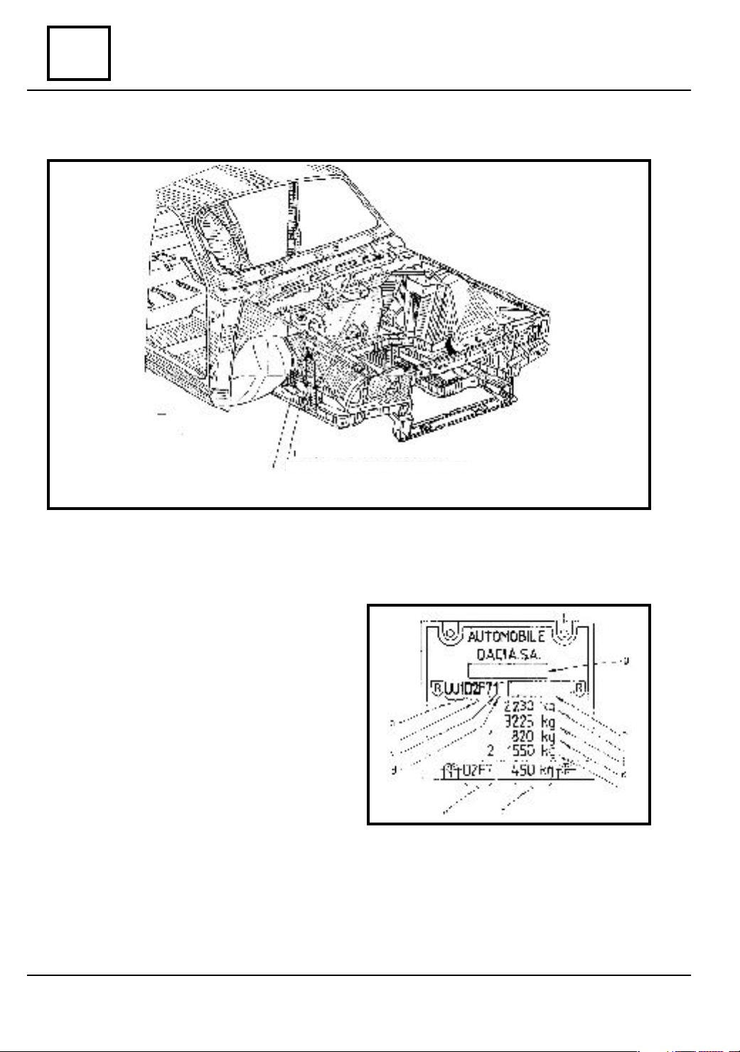
Vehicle identification
UNITL THE DATE OF 26.06.2003
Manufacturer plate
VIN identification number
MANUFACTURER PLATE
a. Manufacturer identification code;
b. Code of the vehicle;
c. Gearbox type code;
d. Engine type code and driving location
(according to VIN code structure);
e. Vehicle code;
f. Trailer maximum authorized weight with-
out braking system;
g. Homologation number for the importer
country
code + 7 characters for the chassis
manufacturing number;
the loaded car
with braking system
on front axle;
rear axle.
;
h. VIS sign; one character for year model
i. Maximum technical admissible weight of
;
j. Maximum admissible weight with trailer
;
k. Maximum technical admissible weight
l. Maximum technical admissible weight on
7
01 - 2

SPECIFICATIONS
vnx.su
01
Vehicle identification
UNITL THE DATE OF 26.06.2003
VEHICLE IDENTIFICATION
VIN IDENTIFICATION NUMBER
Position 1 2 3 4 5 6 7 8 9 10 11 12 13 14 15 16 17
CODE U U 1 D
CODE U U 1 D
CODE U U 1 D
CODE U U 1 D
CODE U U 1 D
CODE U U 1 D
CODE U U 1 D
CODE U U 1 D
CODE U U 1 D
POSITION CHARACTERS EXPLANATION
1 - 3 - manufacturer identification
4 - vehicle type
5 - engine-gearbox unit location
6 - carriage body type
7 - payload location
8 - gearbox type
9 - engine code and vehicle driving location
10 - year model code - 2 - 2002
11 - 17 - chassis manufacturing number
1 6 1 1 * * * * * * * * *
1 7 1 1 * * * * * * * * *
2 6 1 1 * * * * * * * * *
2 7 1 1 * * * * * * * * *
4 6 1 6 * * * * * * * * *
4 7 1 6 * * * * * * * * *
1 F 7 1 * * * * * * * * *
2 F 7 1 * * * * * * * * *
4 F 7 6 * * * * * * * * *
UU1 - AUTOMOBILE DACIA S.A. ROMÂNIA
D - vehicle for goods transportation
1 - longitudinal front engine and front drive
2 - longitudinal front engine and rear drive
4 - longitudinal front engine and four wheel drive (front drive coupling
optional
6 - PICK UP
7 - DROP SIDE
F - PICK UP, DOUBLE CAB
1 - two front seats + bed body
7 - five places : 2 front places + 3 places rear bench + bed body
1 - gearbox with 5 + 1 steps
6 - gearbox with 5 + 1 steps and 4x4 coupling
3
X - motor 1870 cm
type EURO 2, left hand drive
7 - engine 1870 cm
type EURO 3, left hand drive
T - engine 1870 cm
type 1504, left hand drive
with ignition by compression, combustibil (Diesel oil),
3
with ignition by compression, combustibil (Diesel oil),
3
with ignition by compression, combustibil (Diesel oil),
01 - 3

SPECIFICATIONS
vnx.su
01
STARTING WITH THE DATE OF 26.06.2003
MANUFACTURER’S PLATE DISPOSAL TYPE SELF-ADHESIVE
Vehicle identification
Fig.2.1
01 - 4

SPECIFICATIONS
vnx.su
01
Vehicle identification
STARTING WITH THE DATE OF 26.06.2003
The MANUFACTURER PLATE, self-adhesive type, has the bellow presented con-
figuration, with two distinctive areas, presenting :manufacturer’s identification data
and APV type identification data.
A
B
C
D
E
F
G
H
I
J
MANUFACTURER’S IDENTIFICA-
TION DATA
A. Manufacturer’s name
B. Community reception number or
homologation number.
C. Identification number.
D. Total authorized weight of the
loaded vehicle.
E. Total authorized running weight
F. Total weight on front axle.
G. Total weight on rear axle.
H. Additional inscription.
I. Manufacturing date inscription
J. Consignment number.
APV IDENTIFICATION DATA
1.1Code type auto APV
1.2Manufacturing number
2.1 Equipping level code
2.2 Additional code for limited serial
definition
2.3 Additional code for special serial
definition
3.1 Carriage body color code
3.2 Seats upholstery code
3.3 Interior matching code.
4.1 Technical definition code
4.2 Optional equipping code.
01 - 5
LIFTING
vnx.su
Mobile jack – Protection routes
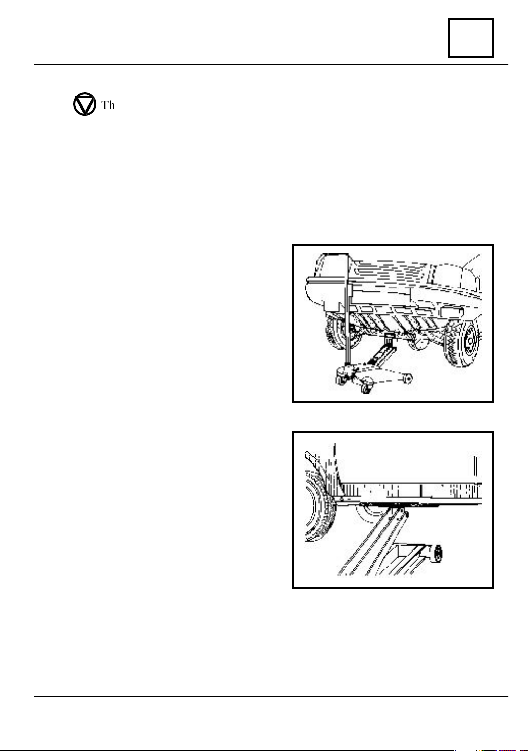
The use of a mobile jack implies the using of protection intermediary routes.
It absolutely forbidden the vehicle lifting using the front or rear suspension arms as
supporting points.
The mobile jack is not to be used for vehicle lifting in order to perform works under the
carriage body (the two columns elevator is to be used).
LIFTING THE FRONT PART
OF THE VEHICLE
In order to lift the front of the vehicle, use
the mobile jack and the protection
intermediary route Cha 280 ( for protection
of the body and mechanical elements) which
are placed on the front longitudinal girders in
the suspension arms axle.
02
LATERAL LIFTING
OF THE VEHICLE
For lateral lifting of the vehicle use the mobile jack and the protection intermediary route
CHA 280; place it under the threshold at the
front door level.
The threshold edge shall be correctly
positioned in the channel of the protection
intermediary route.
02 - 1
LIFTING
vnx.su
02
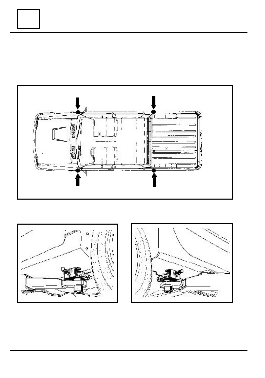
Elevator to be attached under the carriage body
For lifting, place the intermediary routes of the elevator arms in the supporting point of
the vehicle inbuilt used by jack. The threshold edges shall be correctly positioned in the
routes channels.
FRONT
REAR
02 - 2

TOWING
vnx.su
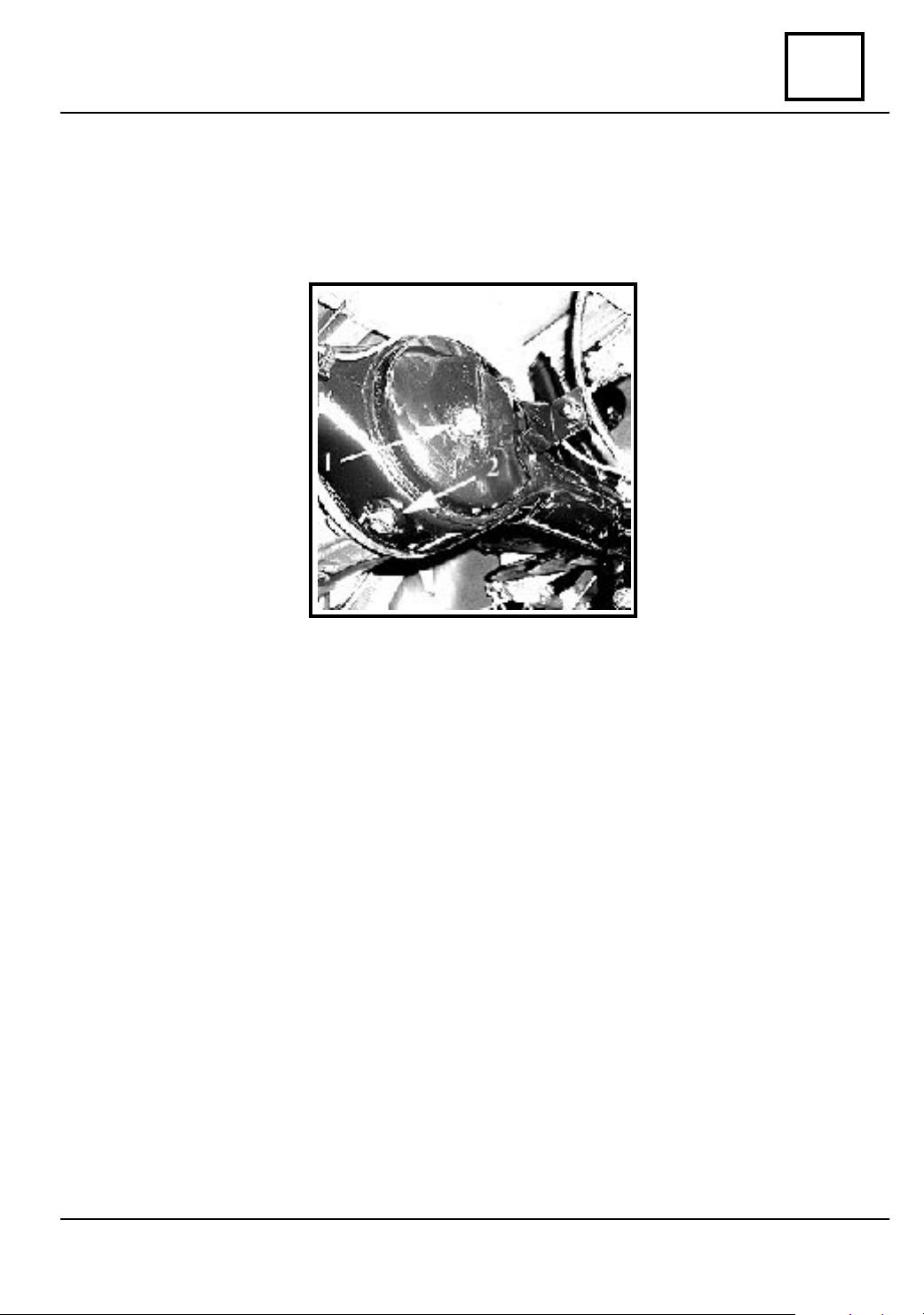
Alltypes
NEVER USE AS TOWING POINTS, THE TRANSMISSION AXLES (PLAN-
ETARY SHAFTS)
The towing points, front (1) or rear (2) are to be used only for vehicles hauling on
wheels, by towing. These points cannot be anyhow used for drawing out the damaged
vehicle from a trench (hole), or for direct or indirect vehicle lifting on a transport platform.
.
03
FRONT (right)
1
REAR (left)
2
03 - 1

LUBRICANTS CONSUMABLES
vnx.su
Condition
PRODUCT PLACE WHERE IT IS USED
LUBRICATION (GREASING )
Front transmission pinion grooves
Grease
UM 170 Li Ca Pb 2M
Gear box control shaft
Cardan flange annular oil seal
04
ELF CARDREXA RNT2 or
UM 185 Li 2M
Grease
UM 185 Li 2M
Grease U 95 Ca 2
Grease
Li Ca Pb tip II cu MoS2
(or 20 UM Li III)
Grease 22
Planetary transmissions
Front wheel steering knuckle grooves
Cardan transmission
Planetary transmission
Front wheel bearing
Suspension ball joints
Rear axle differential
Wheels bolts
Pressure bearing guide
Steering box (gear-rack, bearings)
Clutch shaft grooves
Pressure bearing
Clutch mechanism diaphragm
Steering box rubber gaskets
Grease U100 Ca 4-5
Auxiliary steering connecting rod
04 - 1

LUBRICANTS CONSUMABLES
vnx.su
04
PRODUCT
RHODORSEAL
5661
LOCTITE 518
KIT DURCISSEUR
LOCTITE 577
Condition
PLACE WHERE IT IS USED
SEALING
Camshaft bearing cap no.1 and 5
Crankshaft no.1 bearing cap
Planetary transmission pins
Gearbox half crankcase
Clutch casing
Rear axle
Crankshaft no.1 bearing cap
Rear driving contact thread
Plug M 16- gearbox
Rear axle
Sealant material 503 ( mastic)
LOCTITE FRENETANCH
DECAPJOINT
Rear axle differential
SOLDERING
Flywheel attachment screws
CLEANING
Cylinder head gasket surface
04 - 2
DRAINING AND FILLING
vnx.su
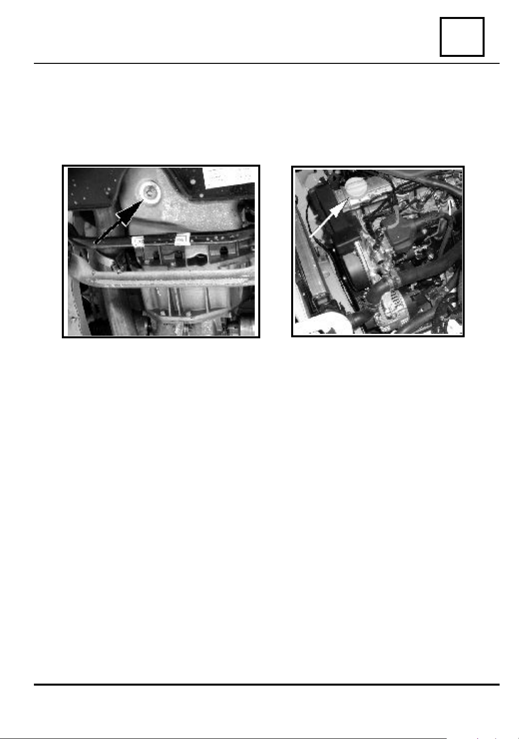
Engine
ENGINE
Necessary special tools - wrench for draining plug : MOT 1018
Draining : plug (2) Filling : plug (1)
05
2
1
05 - 1
05
vnx.su
DRAINING AND FILLING
Gearbox
GEARBOX
Drain : plug (2)
Fill : plug (1)
05 - 2
DRAINING AND FILLING
vnx.su
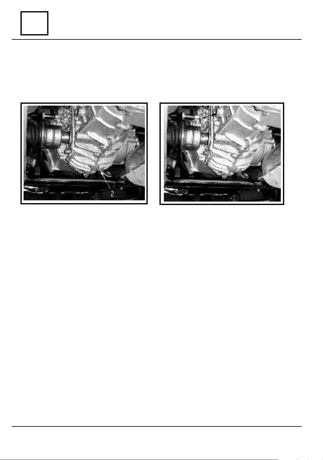
Rear axle differential
REAR AXLE DIFFERENTIAL
Draining: plug (2) Filling: plug (1)
05
05 - 3
VALUES AND SETTINGS
vnx.su
Dimensions
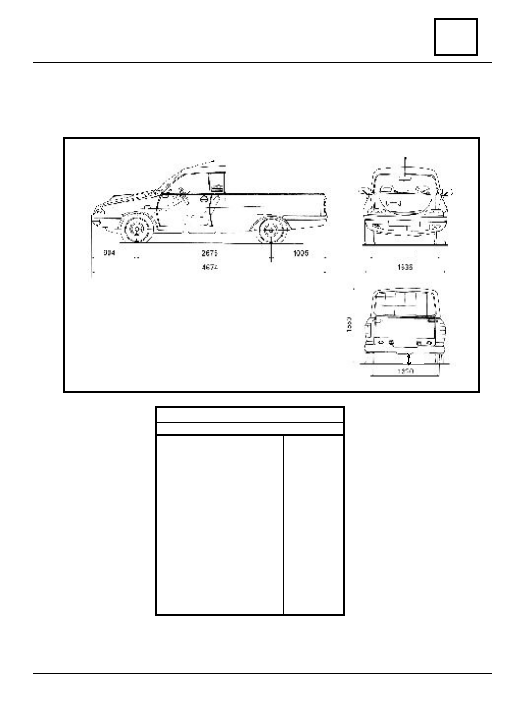
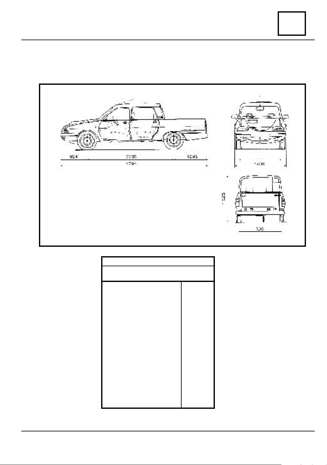
DIMENSIONS
DACIA Pick Up P, 4x4 and T
07
1334
DACIA Pick Up P, 4x4 end T
DIMENSIONS (mm)
Total length
Total width
Total height:
- Empty
- Loaded
Axle base
Front wheel track width
Rear wheel track width
Ground clearance(k):
- Loaded
Turn radius:
- Between footways
- Between walls
k
4674
1636
1550
2675
1334
1320
>140
5600
5800
07 - 1

07
vnx.su
VALUES AND SETTINGS
Dimensions
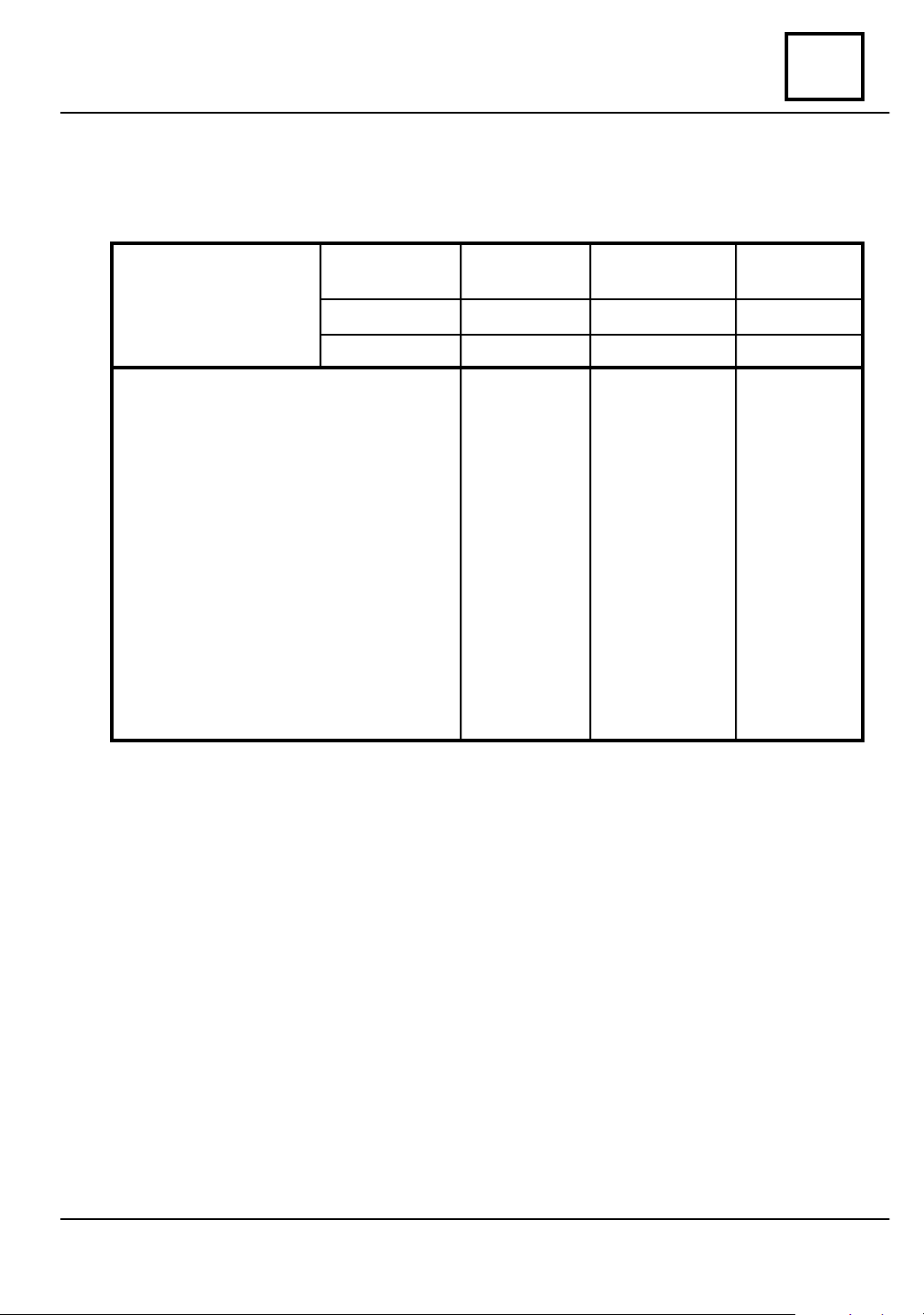
WEIGHTS
DACIA Pick Up P, 4x4 and T
VEHICLE
VEHICLES
WEIGHTS
1. Unloaded vehicle weight
( with 75 Kg. driver)
- on the front axle,
- on the rear axle,
- total.
2. Deadweight
(unloaded vehicle weight):
- on the front axle,
- on the rear axle,
- total.
3. Technical admissible maximal weight
of the loaded vehicle:
- on the front axle,
- on the rear axle,
- total.
DENOMINATION
DRIVE
VIN CODE
:
DACIA
Pick Up P
REAR
D 2611*
635
520
1155
590
490
1080
720
1510
2230
DACIA
Pick Up 4x4
INTEGRAL
D4616*
645
530
1175
600
500
1100
740
1510
2250
DACIA
Pick Up T
FRONT
D 1611*
645
480
1125
600
450
1050
640
1260
1900
4. Technical admissible maximal weight
on each axle:
- on the front axle,
- on the rear axle.
5. Payload:
- on seats,
- on bed body,
- total.
07 - 2
760
1550
150
1000
1150
760
1550
150
1000
1150
760
1300
150
700
850

VALUES AND SETTINGS
vnx.su
Dimensions
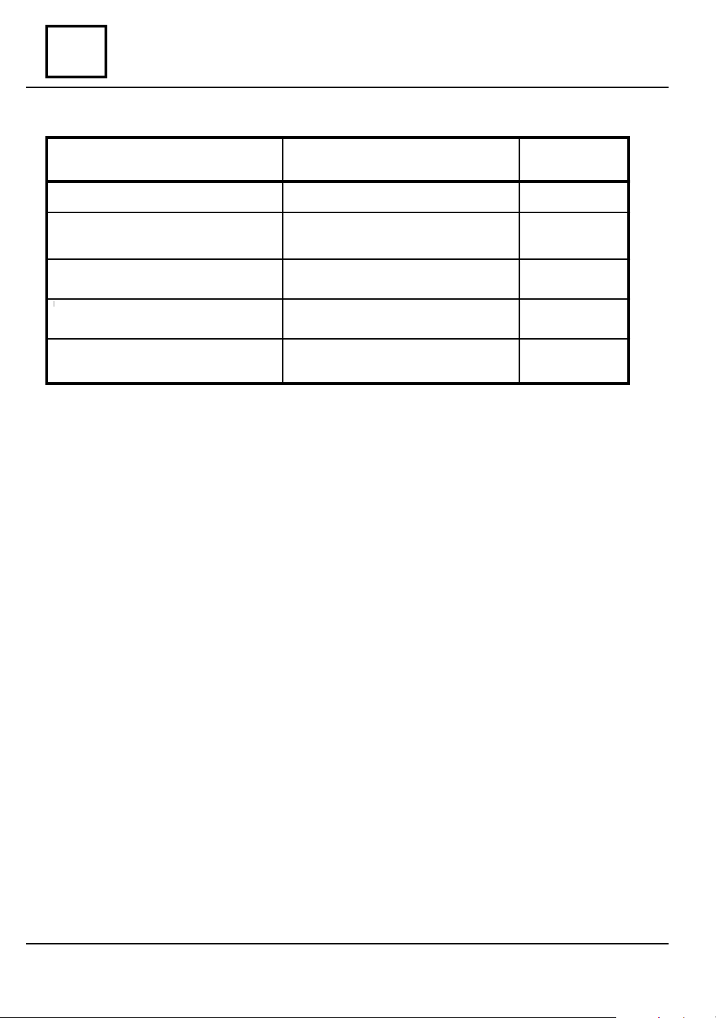
TOWING WEIGHTS
DACIA Pick Up P, 4x4 and T
VEHICLE
TOWING
WEIGHTS
1. Te c hnical admissible maximal weight for
towing (trailer with braking system)
2. Admissible maximal weight of the assembly
3. The vehicle is capable / is not capable for
trailer towing
4. To w ing maximal weight without braking
system.
DENOMINATION
DRIVE
VIN CODE
DACIA
Pick Up P
REAR
D 2611*
1095
3225**
capable
450*
DACIA
Pick Up 4x4
INTEGRAL
D 4616*
1075
3225**
capable
450*
07
DACIA
Pick Up T
FRONT
D 1611*
0
not applicable
not capable
0
5. Te c hnical admissible maximal weight on
towing coupling point
** By reducing the bed payload with 100 Kg.
50
50
-
07 - 3
VALUES AND SETTINGS
vnx.su
07
Dimensions
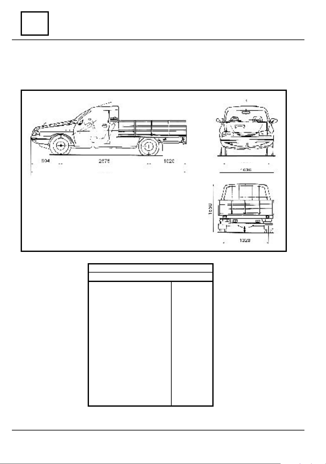
DIMENSIONS
DACIA Drop Side P, 4x4 and T
1334
4599
DACIA Drop Side P, T ºi 4x4
DIMENSIONS (mm)
Total length
Total width
Total height:
- Empty
- Loaded
Axle base
Front wheel track width
Rear wheel track width
Ground clearance (k):
- Loaded
Turn radius:
- Between footways
- Between walls
k
4599
1636
1550
-
2675
1334
1320
> 140
5600
5800
07 - 4

VALUES AND SETTINGS
vnx.su
VEHICLE
VEHICLES
WEIGHTS
1. Unloaded vehicle weight
(with 75 Kg. driver)
- on the front axle,
- on the rear axle,
- total.
DENOMINATION
DRIVE
VIN CODE
:
Dimensions
WEIGHTS
DACIA Drop Side P, 4x4 and T
DACIA
Drop Side P
REAR
D 2711*
635
555
1190
DACIA
Drop Side 4x4
INTEGRAL
D 4716*
1210
645
565
07
DACIA
Drop Side T
FRONT
D 1711*
645
510
1155
2. Deadweight
(unloaded vehicle weight):
- on the front axle,
- on the rear axle,
- total.
3. Technical admissible maximal
weight of the loaded vehicle:
- on the front axle,
- on the rear axle,
- total.
4. Technical admissible maximal
weight on each axle:
- on the front axle,
- on the rear axle.
5. Payload:
- on seats,
- on bed body,
- total.
590
525
1115
690
1540
2230
760
1550
150
965
1115
600
535
1135
690
1540
2230
760
1550
150
945
1095
600
480
1080
690
1240
1930
760
1300
150
150
700
07 - 5
VALUES AND SETTINGS
vnx.su
07
DACIA Drop Side P, 4x4 and T
TOWING
WEIGHTS
1. Te c hnical admissible maximal weight for
towing (trailer with braking system)
2. Admissible maximal weight of the assembly
3. The vehicle is capable / is not capable for
trailer towing
DENOMINATION
VIN CODE
Dimensions
TOWING WEIGHTS
VEHICLE
DRIVE
DACIA
Drop Side P
REAR
D 2711*
1060
3225**
capable
DACIA
Drop Side 4x4
INTEGRAL
D 4716*
1040
3225**
capable
DACIA
Drop SideT
FRONT
D 1711*
0
not
applicable
not capable
4. To w ing maximal weight without braking
system
5. Te c hnical admissible maximal weight on
towing coupling point
** By reducing the bed payload with 100 Kg.
450*
50
450*
50
0
-
07 - 6
VALUES AND SETTINGS
vnx.su
Dimensions
DIMENSIONS
DACIA Double Cab P, 4x4 and T
07
1334
DACIA Double Cab P, 4x4 ºi T
DIMENSIONS (mm)
Total length
Total width
Total height:
- Empty
- Loaded
Axle base
Front wheel track width
Rear wheel track width
Ground clearance (k):
- Loaded
Turn radius:
- Between footways
- Between walls
k
4794
1636
1525
-
2795
1334/1312
1320
>140
5600
5800
07 - 7

VALUES AND SETTINGS
vnx.su
07
DACIA Double Cab P, 4x4 and T
VEHICLE
VEHICLES
WEIGHTS
1. Unloaded vehicle weight
(with 75 Kg. driver)
- on the front axle,
- on the rear axle,
- total.
2. Deadweight
(unloaded vehicle weight):
- on the front axle,
- on the rear axle,
- total.
DENOMINATION
VIN CODE
:
DRIVE
Dimensions
WEIGHTS
DACIA
Double Cab P
REAR
D 2F71*
680
570
1250
635
540
1175
DACIA
Double Cab 4x4
INTEGRAL
D 4F76*
690
580
1270
645
550
1195
DACIA
Double Cab T
FRONT
D 1F71*
690
530
1120
645
500
1145
3. Technical admissible maximal
weight of the loaded vehicle:
- on the front axle,
- on the rear axle,
- total.
4. Technical admissible maximal
weight on each axle:
- on the front axle,
- on the rear axle.
5. Payload:
- on seats,
- on bed body,
- total.
710
1520
2230
820
1550
375
680
1055
730
1520
2250
820
1550
375
680
1055
710
1260
1970
820
1300
375
450
825
07 - 8
VALUES AND SETTINGS
vnx.su
Dimensions
TOWING WEIGHTS
DACIA Double Cab P, 4x4 and T
VEHICLE
TOWING
WEIGHTS
1. Te c hnical admissible maximal weight
for towing (trailer with braking system)
2. Admissible maximal weight of the assembly
3. The vehicle is capable / is not capable
for trailer towing
DENOMINATION
DRIVE
VIN CODE
DACIA
Double Cab P
REAR
D 2F71*
1095
3225**
capable
DACIA
Double Cab 4x4
INTEGRAL
D 4F76*
1075
3225**
capable
07
DACIA
Double Cab T
FRONT
D 1F71*
0
not
applicable
not
applicable
4. To w ing maximal weight without braking system
5. Te c hnical admissible maximal weight
on towing coupling point
** By reducing the bed payload with 100 Kg.
450**
50
450**
50
0
-
07 - 9
07
vnx.su
VALUES AND SETTINGS
Capacity - Qualities
DENOMINATION
Engine oil Dacia Oil Diesel
Gearbox oil DACIA OIL
SUPERGEAR
The rear axle group oil DACIA
OIL SUPERGEAR
Brake fluid
Cooling fluid
* To be ajusted at dipstick
** Mixture : 50% concentrated anti-freeze + 50% distilled water.
**
SAE API 10W40 ACEA B3 CF
SAE 80 W 90/GL5
SAE 80 W 90 / GL5
SAE J 1703 DOT 4
Typ e D - GLACEOL RX
QUALITY
CAPACITY
(liters)
4,6*
2,3
2
0,450
6
07 - 10

VALUES AND SETTINGS
vnx.su
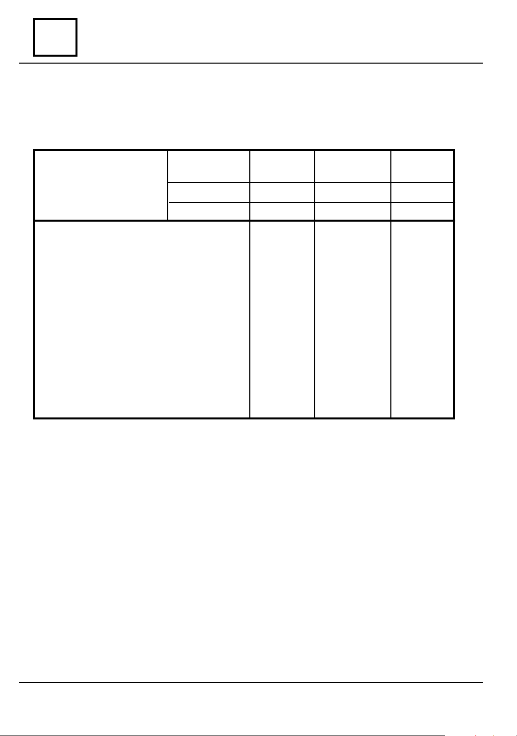
Wheels and tires
VEHICLE
TYPE
DACIA Pic k Up T, P ºi 4x4
DACIA Drop Si de T, P ºi 4x4
DACIA Doub le Cab T, P ºi 4x4
(1) Using maximum loading, wheels on ground.
• Tightening moment of the wheels screws: 9 daNm.
• Rim axial run out: maxim 1,2 mm.
• Rim radial run out: maxim 1,2 mm.
RIMS TIRES
5 J 14
175 R 14
PR 8
ROLLING
CIRCUMFERENCE
1920 ± 25
07
PRESSURE
(bari) (1)
(mm)
FRONT REAR
2,0 4,5
ATT EN TI ON!
The increase of tire temperature during running implies a growth of the tire pres-
sure with 0.2 – 0.3 bars compared with the prescribed values.
In case of checking the tires pressure immediately after vehicle driving, consider
this growth of pressure.
07 - 11
07
vnx.su
VALUES AND SETTINGS
Brakes
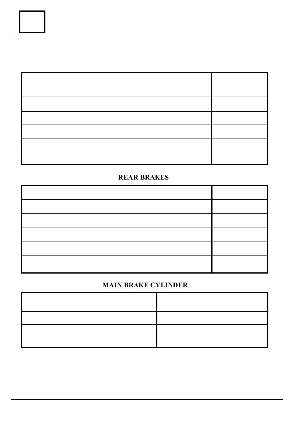
FRONT BRAKES
Brake caliper bore diameter (for aerated brake disk)
Disk thickness aerated
Minimal disk thickness aerated
Brake pad thickness ( the support included)
Minimal brake pad thickness (the support included)
Disk axial run out, measured at → 215 mm
REAR BRAKES
Wheel braking cylinder diameter
New drum diamete
Maximum drum diameter after grinding
Braking lining width
Braking lining thickness
Φ 54 mm
20 mm
19 mm
14 mm
7 mm
0,1 mm
Φ 25,4 mm
Φ 254 mm
Φ 255 mm
50 mm
5 mm
Minimal accepted braking lining height above rivets
MAIN BRAKE CYLINDER
Tandem master cylinder with ICP by
Type of main brake cylinder
nner diameter
Stroke - primary piston
- secondary piston
• Brake fluid reservoir - double without level warning.
• Pressure reducing valve - for parallel circuit.
• Brake fluid - norm SAE J 1703 DOT4.
• Servobrake - master vac 8" 224 mm
07 - 12
pass included
Φ 22,2 mm
min. 19 mm
min. 13 mm
0,5 mm
VALUES AND SETTINGS
vnx.su
Heights under carriage body
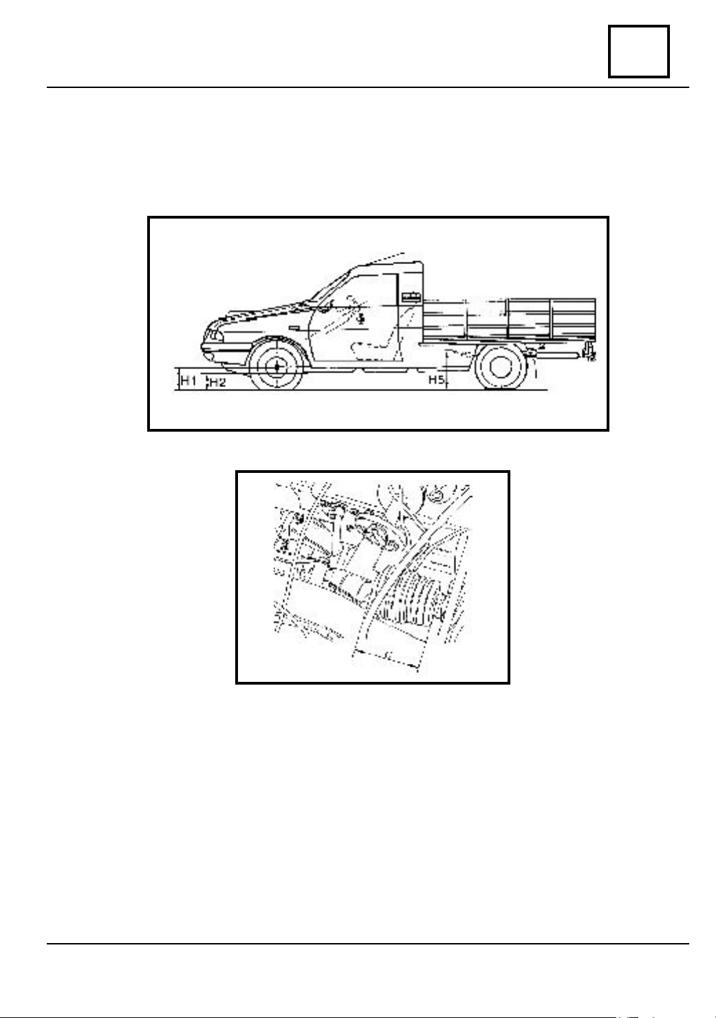
VA LUES UNDER CARRIAGE BODY CONDITIONING THE ADJUSTMENT
OPERATIONS OF THE STEERING ANGLES.
07
H1 – the distance measured from the wheels center to the ground
H2 – the distance measured from the longitudinal girder lower part to the ground
H5 – the distance measured from the joint axis of the front leaf spring to the ground,
measured in the area of the lower arm attachment.
C – this value is showing the position where the rack must reach in order to obtain
the middle point for the steering rack.
07 - 13
07
vnx.su
VALUES AND SETTINGS
Control values of front the axle angles
COMMERCIAL U 75 DRIVE (1304, 1307)
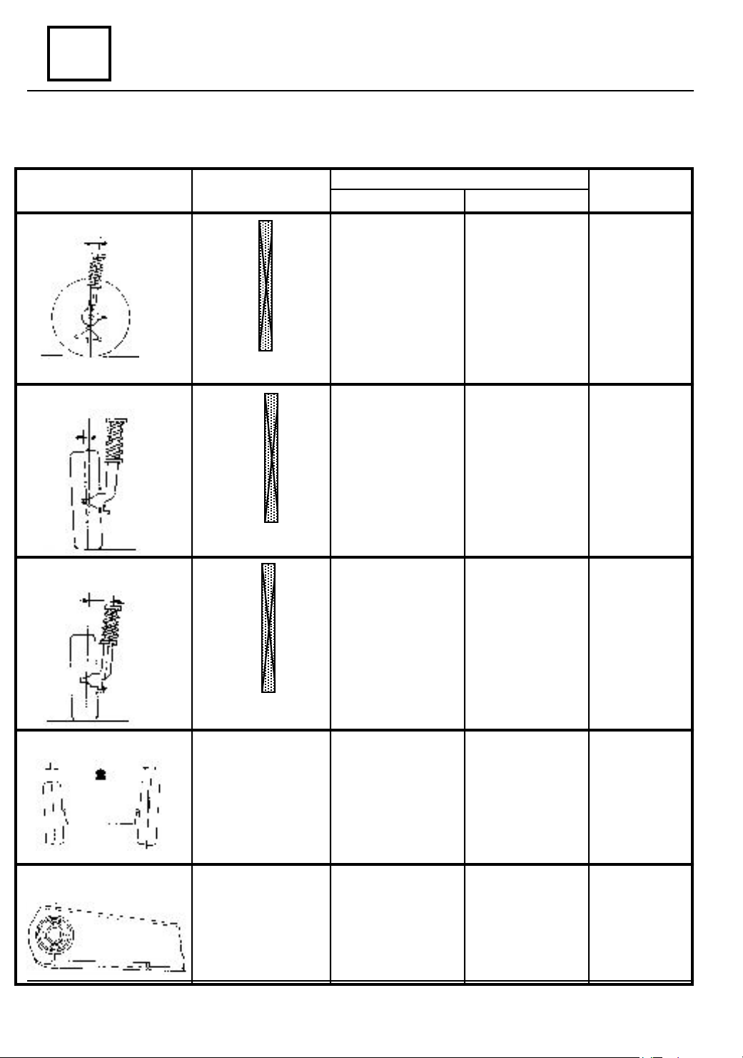
ANGLES
CASTER
CAMBER
BALL JOINT
TOTAL PARALLELISM
VA L U ES
0
11'
1
0
28'
1
0
45' ± 30'
1
0
02'
2
0
19'
2
0
0
36'
52'
2
2
Maximum Left /
Right difference = 1
10 22'
0
1
21'
0
20'
1
0
18' ± 30'
1
0
17'
1
0
15'
1
0
14'
1
Maximum Left /
Right difference = 1
80 01'
0
02'
8
0
03'
8
0
04' ±30'
8
0
05'
8
0
07'
8
0
08'
8
Maximum Left /
Right difference = 1
POSITION OF THE VEHICLE
1304
H5 - H2 = 260
H5 - H2 = 250
H5 - H2 = 240
H5 - H2 = 230
H5 - H2 = 220
H5 - H2 = 210
H5 - H2 = 200
0
H1 - H2 = 66
H1 - H2 = 62
H1 - H2 = 58
H1 - H2 = 54
H1 - H2 = 51
H1 - H2 = 47
H1 - H2 = 43
0
H1 - H2 = 66
H1 - H2 = 62
H1 - H2 = 58
H1 - H2 = 54
H1 - H2 = 51
H1 - H2 = 47
H1 - H2 = 43
0
H5 - H2 = 265
H5 - H2 = 255
H5 - H2 = 245
H5 - H2 = 235
H5 - H2 = 225
H5 - H2 = 215
H5 - H2 = 205
H1 - H2 = 66
H1 - H2 = 62
H1 - H2 = 58
H1 - H2 = 54
H1 - H2 = 51
H1 - H2 = 47
H1 - H2 = 43
H1 - H2 = 66
H1 - H2 = 62
H1 - H2 = 58
H1 - H2 = 54
H1 - H2 = 51
H1 - H2 = 47
H1 - H2 = 43
ADJUSTMENTS
1307
Adjustable by
modification of
the tie-rod
length from
previous
mounting
Not adjustable
Not adjustable
ELASTIC JOINTS BLOCKING
Opening (toe-in)
0
10’ ± 10’
0
(for one wheel
0
05’ ± 05”)
0
-
Empty
Empty
07 - 11
Empty
Adjustable by
means of the
tie rods rota-
tion
Empty
-
Loading...