

Page 1

DUSTER
DRIVER’S HANDBOOK
Page 2
RENAULT recommends ELF
ELF has developed a complete range of lubricants for RENAULT:
f engine oils
f manual and automatic gearbox oils
Warning: to ensure the engine operates optimally, the use
of a lubricant may be restricted to certain vehicles. Please
refer to your maintenance document.
Benefiting from the research applied to Formula 1,
lubricants are very high-tech products.
Updated with the help of RENAULT’s technical
teams, this range is perfectly compatible with the
specific features of the brand’s vehicles.
f ELF lubricants enhance
your vehicle’s performance significantly.
RENAULT recommends approved ELF lubricants for oil changes and top-ups.
Contact your RENAULT Dealer or visit www.lubrifiants.elf.com
Photo credit: Total/DPPI Imacom group
Une marque de
Page 3
Welcome aboard your vehicle
This Driver’s Handbook contains the information necessary:
– for you to familiarise yourself with your vehicle, to use it to its best advantage and to benefit fully from the all the functions and
the technical developments it incorporates.
– to ensure that it always gives the best performance by following the simple, but comprehensive advice concerning regular main-
tenance.
– to enable you to deal quickly with minor faults not requiring specialist attention.
It is well worth taking a few minutes to read this handbook to familiarise yourself with the information and guidelines it contains
about the vehicle and its functions and new features. If certain points are still unclear, our Network technicians will be only too
pleased to provide you with any additional information.
The following symbol will help you when reading this handbook:
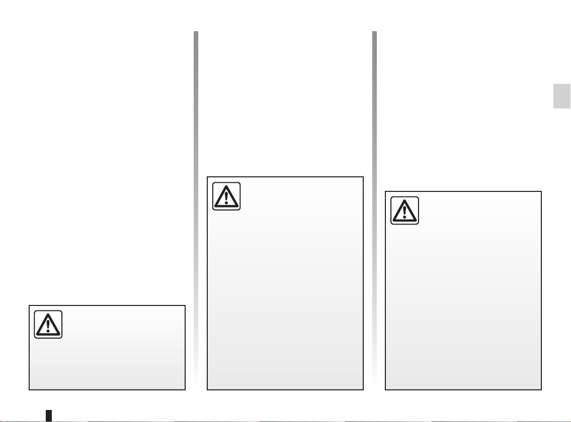
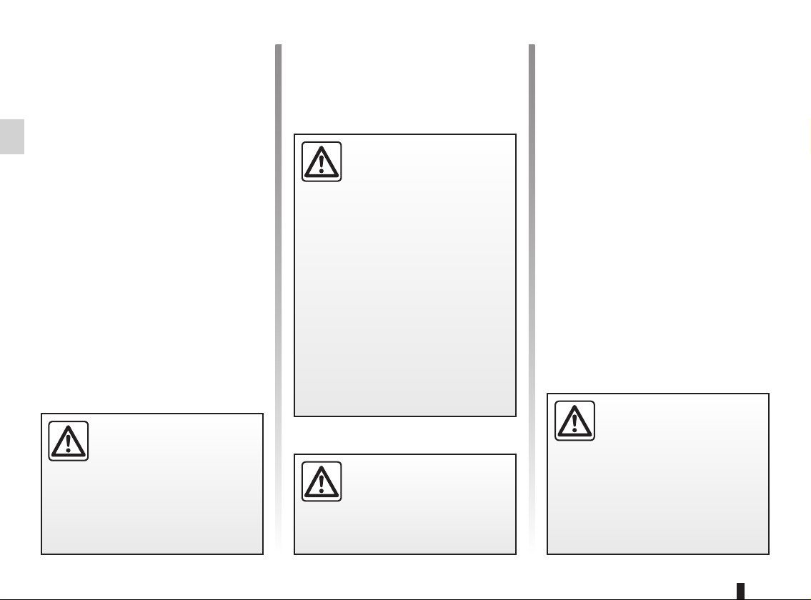
To indicate a hazard, danger or safety recommendation.
The descriptions of the models given in this handbook are based on the technical specifications at the time of writing. This handbook covers all items of equipment (both standard and optional) available for these models, but whether or not these are
fitted to the vehicle depends on the version, options selected and the country where the vehicle is sold.
This handbook may also contain information about items of equipment to be introduced later in the model year.
Throughout the manual, the “approved dealer” is your DACIA dealer.
Enjoy driving your new vehicle.
Translated from French. Copying or translation, in part or in full, is forbidden unless prior written permission has been obtained from the vehicle manufac-
turer.
0.1
Page 4

0.2
Page 5

C O N T E N T S
Sections
Getting to know your vehicle ...............................
Driving ...................................................................
Your comfort .........................................................
Maintenance .........................................................
Practical advice ....................................................
Technical specifications ......................................
Alphabetical index ...............................................
1
2
3
4
5
6
7
0.3
Page 6

0.4
Page 7

Section 1: Getting to know your vehicle
Keys/Radio frequency remote control . . . . . . . . . . . . . . . . . . . . . . . . . . . . . . . . . . . . . . . . . . . . . . . . 1.2
Locking and unlocking the doors . . . . . . . . . . . . . . . . . . . . . . . . . . . . . . . . . . . . . . . . . . . . . . . . . . . . 1.5
Opening and closing the doors . . . . . . . . . . . . . . . . . . . . . . . . . . . . . . . . . . . . . . . . . . . . . . . . . . . . . 1.7
Engine immobiliser system . . . . . . . . . . . . . . . . . . . . . . . . . . . . . . . . . . . . . . . . . . . . . . . . . . . . . . . . 1.8
Headrests . . . . . . . . . . . . . . . . . . . . . . . . . . . . . . . . . . . . . . . . . . . . . . . . . . . . . . . . . . . . . . . . . . . . . 1.9
Front seats. . . . . . . . . . . . . . . . . . . . . . . . . . . . . . . . . . . . . . . . . . . . . . . . . . . . . . . . . . . . . . . . . . . . . 1.11
Seat belts. . . . . . . . . . . . . . . . . . . . . . . . . . . . . . . . . . . . . . . . . . . . . . . . . . . . . . . . . . . . . . . . . . . . . . 1.12
Methods of restraint in addition to the front seat belts . . . . . . . . . . . . . . . . . . . . . . . . . . . . . . . . . . . . 1.16
Side protection devices . . . . . . . . . . . . . . . . . . . . . . . . . . . . . . . . . . . . . . . . . . . . . . . . . . . . . . . . . . . 1.19
Additional methods of restraint . . . . . . . . . . . . . . . . . . . . . . . . . . . . . . . . . . . . . . . . . . . . . . . . . . . . . 1.20
Child safety: general information . . . . . . . . . . . . . . . . . . . . . . . . . . . . . . . . . . . . . . . . . . . . . . . . . . . . 1.21
mounting a child seat . . . . . . . . . . . . . . . . . . . . . . . . . . . . . . . . . . . . . . . . . . . . . . . . . . . . . . . 1.24
fitting a child seat . . . . . . . . . . . . . . . . . . . . . . . . . . . . . . . . . . . . . . . . . . . . . . . . . . . . . . . . . . 1.26
deactivating/activating the front passenger airbag . . . . . . . . . . . . . . . . . . . . . . . . . . . . . . . . . 1.32
Rear-view mirrors . . . . . . . . . . . . . . . . . . . . . . . . . . . . . . . . . . . . . . . . . . . . . . . . . . . . . . . . . . . . . . . 1.35
Driving position . . . . . . . . . . . . . . . . . . . . . . . . . . . . . . . . . . . . . . . . . . . . . . . . . . . . . . . . . . . . . . . . . 1.36
Instrument panel: warning lights . . . . . . . . . . . . . . . . . . . . . . . . . . . . . . . . . . . . . . . . . . . . . . . . . . . . 1.40
Display and indicators . . . . . . . . . . . . . . . . . . . . . . . . . . . . . . . . . . . . . . . . . . . . . . . . . . . . . . . . . . . . 1.44
On-board computer . . . . . . . . . . . . . . . . . . . . . . . . . . . . . . . . . . . . . . . . . . . . . . . . . . . . . . . . . . . . . . 1.46
Steering wheel, Power-assisted steering . . . . . . . . . . . . . . . . . . . . . . . . . . . . . . . . . . . . . . . . . . . . . 1.50
Clock . . . . . . . . . . . . . . . . . . . . . . . . . . . . . . . . . . . . . . . . . . . . . . . . . . . . . . . . . . . . . . . . . . . . . . . . . 1.51
Audible and visual signals . . . . . . . . . . . . . . . . . . . . . . . . . . . . . . . . . . . . . . . . . . . . . . . . . . . . . . . . . 1.52
Exterior lighting and signals. . . . . . . . . . . . . . . . . . . . . . . . . . . . . . . . . . . . . . . . . . . . . . . . . . . . . . . . 1.54
Adjusting the headlight beam height . . . . . . . . . . . . . . . . . . . . . . . . . . . . . . . . . . . . . . . . . . . . . . . . . 1.56
Windscreen washer/wiper, De-icing . . . . . . . . . . . . . . . . . . . . . . . . . . . . . . . . . . . . . . . . . . . . . . . . . 1.57
Fuel tank (filling with fuel) . . . . . . . . . . . . . . . . . . . . . . . . . . . . . . . . . . . . . . . . . . . . . . . . . . . . . . . . . 1.60
1.1
Page 8
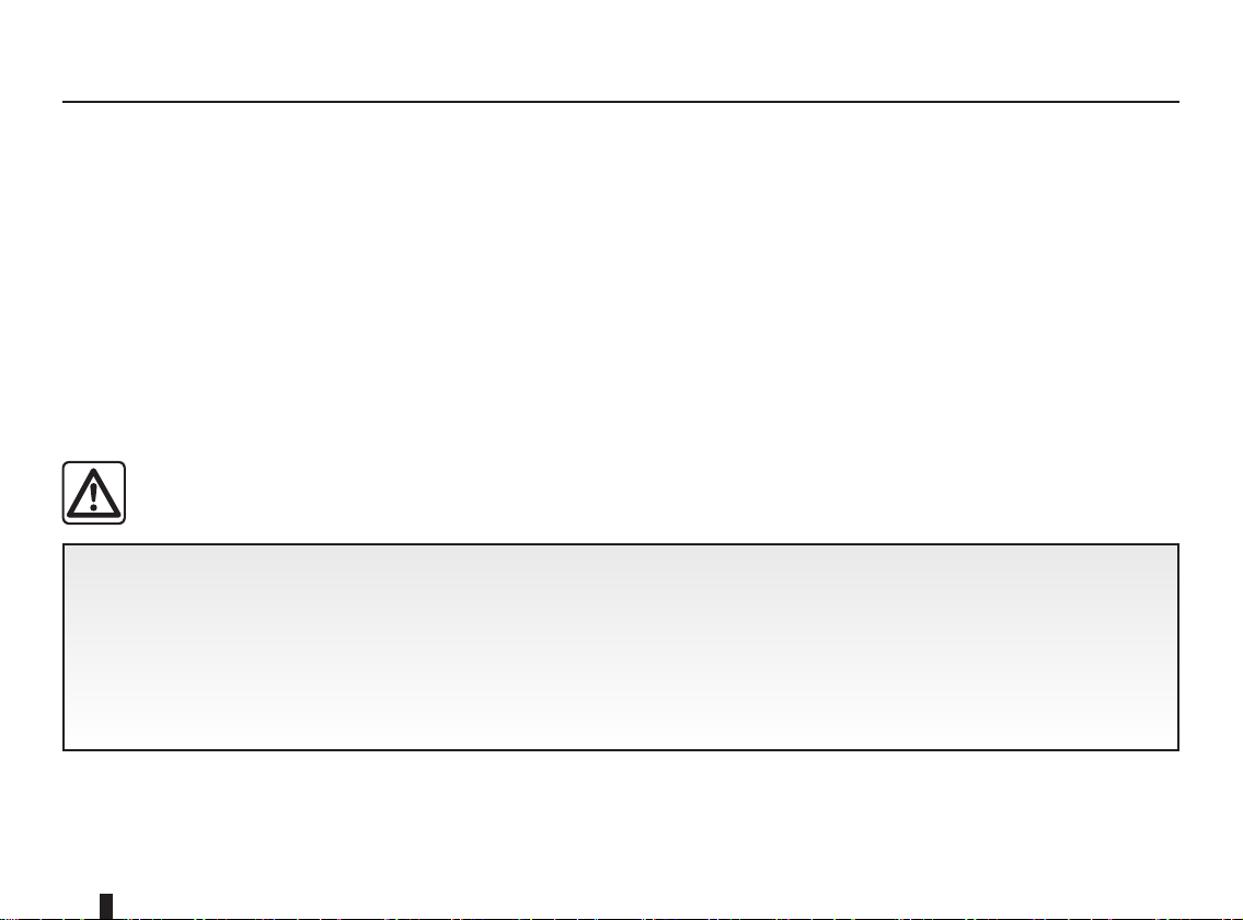
KEYS, RADIO FREQUENCY REMOTE CONTROL: general information (1/2)
A
1
Key A
1 Coded key for ignition switch,
doors and fuel filler cap.
The key must not be used for any
function other than those described
in the handbook (removing the cap
from a bottle, etc.).
B
2
3
4
Radio frequency remote
control B
2 Locking the doors and tailgate.
3 Unlocking the doors and tailgate.
4 Coded key for ignition switch, driv-
er’s door and fuel filler cap.
Advice
Avoid leaving the remote control in
hot, cold or humid areas.
Driver’s responsibility
Never leave your vehicle
with the key or remote con-
trol inside and never leave a
child (or a pet) unsupervised, even
for a short while.
The reason for this is that the child
may endanger himself or others by
starting the engine, activating equipment such as the window winders
for example, or locking the doors.
Risk of serious injury.
1.2
Page 9

KEYS, RADIO FREQUENCY REMOTE CONTROL: general information (2/2)
The remote control unit
operating range
This varies according to the environment. It is therefore important when
handling the remote control to ensure
that you do not lock or unlock the vehicle by inadvertently pressing the buttons.
Interference
The presence of certain objects (metal
objects, mobile telephones, or an area
with strong electromagnetic radiation,
etc.) close to the key may create interference and affect the operation of the
system.
Replacement and additional keys
or remote controls.
You must only contact an approved
Dealer:
– If you need to replace a key it will
be necessary to take the vehicle
and all of its keys to an approved
Dealer in order to initialise the
system.
– depending on the vehicle, you
have the option of using up to
four remote controls.
Remote control unit failure
Make sure that the correct battery
type is being used, and that the
battery is in good condition and inserted correctly. These batteries
should have a service life of approximately two years.
Refer to Section 5: “Radio frequency remote control: batteries”
for the battery changing procedure.
1.3
Page 10
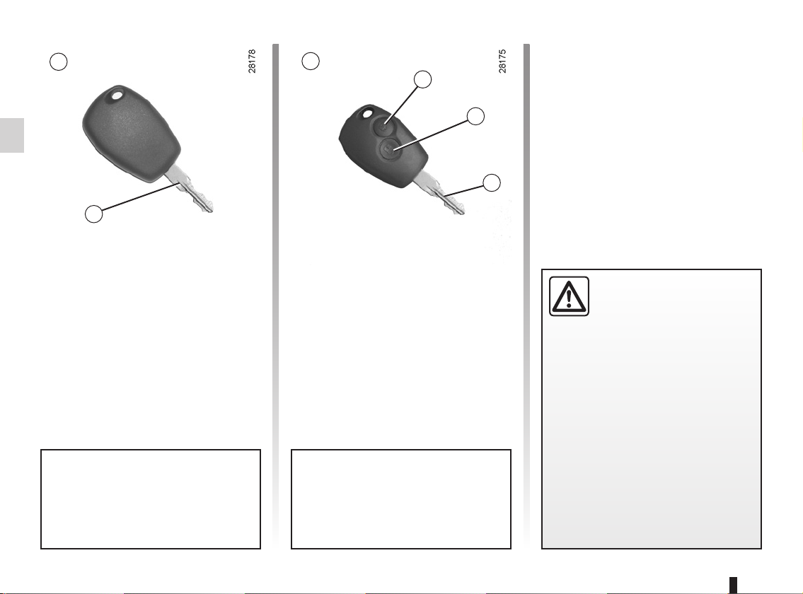
RADIO FREQUENCY REMOTE CONTROL: use
Doors are locked and unlocked using
remote control unit B.
It is powered by a battery which must
be replaced (refer to the information on
the “Radio frequency remote control:
batteries” in Section 5).
B B
1
2
1.4
Locking the doors
Press locking button 1.
The hazard warning lights and side in-
dicator lights flash twice to indicate
that the doors have locked.
If a door or the tailgate is open or not
properly shut, the doors and tailgate
lock then quickly unlock and the hazard
warning lights and side indicator lights
do not flash.
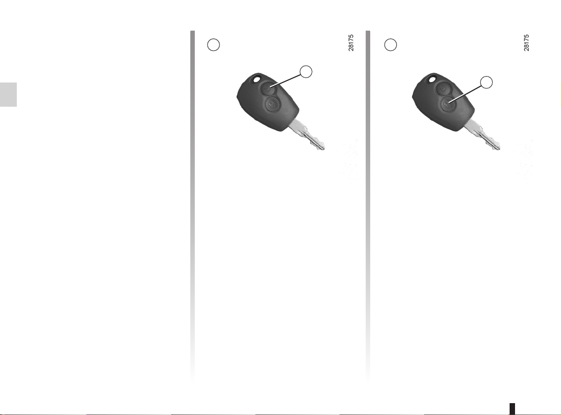
Unlocking the doors
Press unlocking button 2.
The hazard warning lights and side in-
dicator lights flash once to indicate that
the doors have unlocked.
Page 11
LOCKING AND UNLOCKING THE DOORS (1/2)
2
1
Manual locking
From the outside
Unlock the doors using the remote control (refer to information on the “Radio
frequency remote control: use” in
Section 1) or using the key in one of the
door locks.
Depending on the vehicle, the key locks
and unlocks the driver’s door or all four
doors.
From the inside
(depending on vehicle)
Push in button 1 to lock and lift button 1
to unlock.
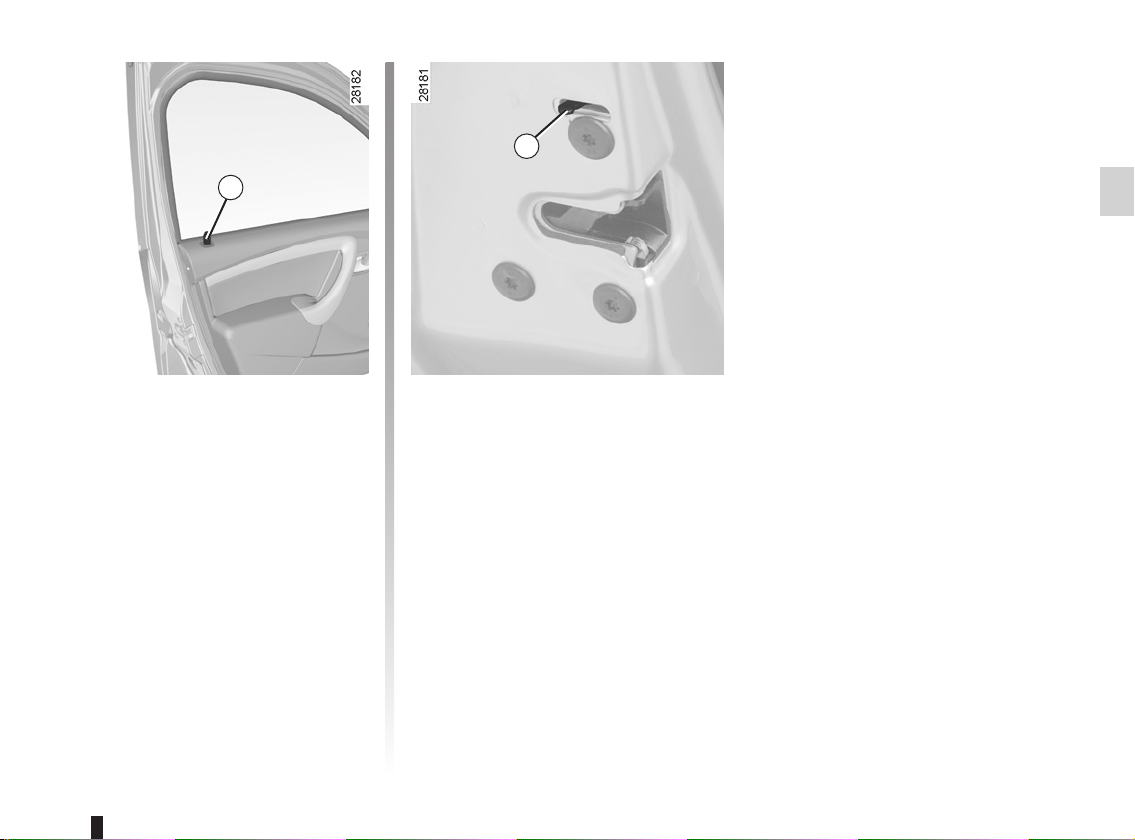
Child safety
To make it impossible for the rear doors
to be opened from the inside, move
lever 2 on each door and check from
the inside that the doors are securely
locked.
1.5
Page 12
LOCKING AND UNLOCKING THE DOORS (2/2)
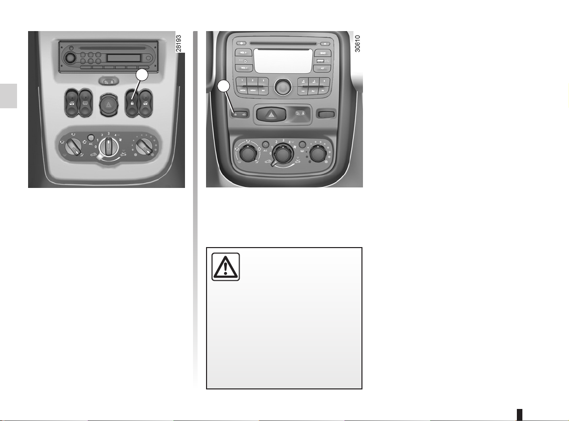
3
3
Electric central locking
Depending on the vehicle, it can be
used to simultaneously lock or unlock
the four doors and the boot. Lock or
unlock the doors by pressing switch 3.
The front door mechanism cannot be
locked if the door is open.
may be more difficult for those assisting you to gain access to the
passenger compartment in the
event of an emergency.
Driver’s responsibility
If you decide to keep the
doors locked when you are
driving, remember that it
1.6
Page 13
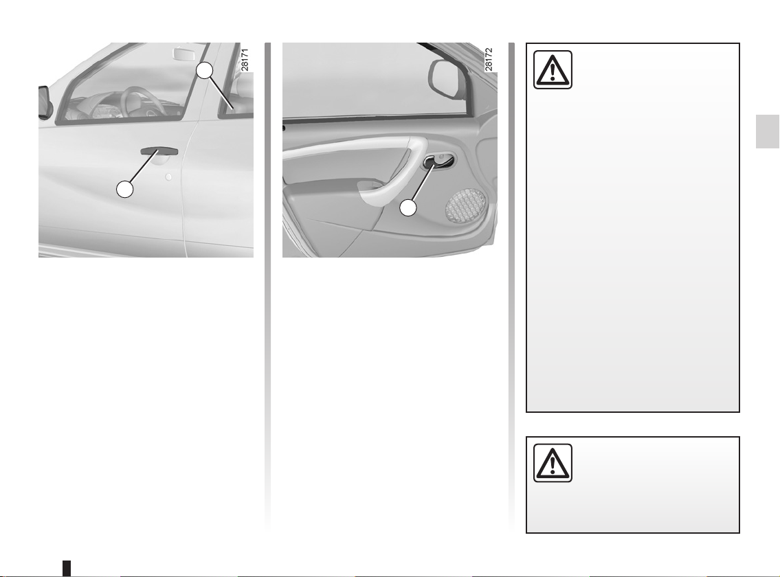
OPENING AND CLOSING THE DOORS
2
1
Opening from the outside
With the doors unlocked (refer to the
information on “Locking/unlocking the
doors” in Section 1).
Front: place your hand behind handle 1
and pull it towards you..
Rear (manual opening): lift unlocking
button 2 from the inside and move the
door handle.
Opening from the inside
Front: pull handle 3
Rear: from the inside, lift unlocking
button 2 and pull door handle 3.
Lights-on reminder buzzer
If you have left the lights on after switching off the ignition, a warning buzzer will
sound when a front door is opened (to
prevent the battery from discharging,
etc.).
Driver’s responsibility
when parking or stopping
the vehicle
child or adult who is not self-sufficient alone on your vehicle, even for
a short time.
They may pose a risk to themselves
or to others by starting the engine,
activating equipment such as the
3
electric windows or by locking the
doors.
Also, in hot and/or sunny weather,
please remember that the temperature inside the passenger compartment increases very quickly.
RISK OF DEATH OR SERIOUS
INJURY.
Never leave an animal,
As a safety precaution,
the doors should only be
opened or closed when the
vehicle is stationary.
1.7
Page 14
ENGINE IMMOBILISER
This prevents the vehicle being
driven by anyone not in possession
of the vehicle’s coded ignition key.
Operating principle
The vehicle is automatically protected
a few seconds after the ignition is
switched off.
If the vehicle does not recognise the
coded ignition key, tell-tale light 1 will
flash continuously and the engine
cannot be started.
Any unauthorised work
carried out on the engine
immobiliser (computers,
wiring, etc.) could be dangerous. Work must be carried out
by qualified personnel.
1
System operation
When the ignition is switched on, telltale 1 lights up continuously for approximately three seconds and then goes
out. The vehicle has recognised the
code. You can then start the engine.
Vehicle protection
A few seconds after the ignition has
been switched off, tell-tale light 1 will
flash constantly.
The vehicle will only be protected after
the ignition has been switched off.
Operating faults
After the ignition has been switched
on, if warning light 1 continues to flash
or remains continuously lit, there is a
system operating fault.
In all cases, it is essential to contact
an approved dealer as only they are
qualified to repair the engine immobiliser.
If the coded ignition key is faulty,
use the second key (supplied with
the vehicle).
1.8
Page 15
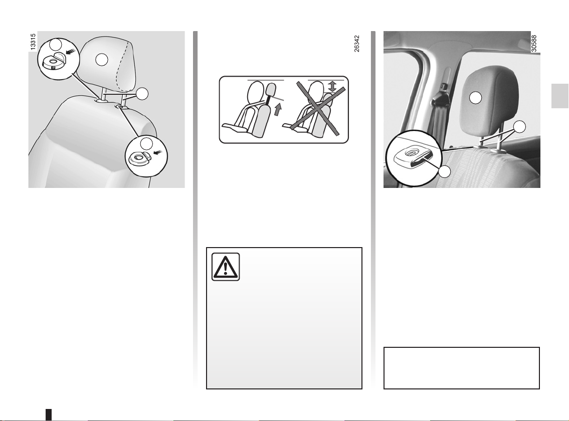
FRONT HEADRESTS
1
A
2
3
Adjusting the height of headrest A
Press tab 1 and simultaneously slide
the headrest to the required position.
To raise the headrests A or B
Depending on the vehicle, press tabs 1
and 2 on the head restraint guides or
on button 3 or 4 and lift the headrest to
release it (tilt the seatback backwards if
necessary).
B
2
4
To refit headrests A or B
Insert headrest rods 2 into the holes (tilt
the seatback backwards if necessary).
Push the headrest in until it locks in position.
The headrest is a safety
component. Ensure that it is
fitted and in the correct po-
sition: the top of your head
should be in line with the top of the
headrest.
Headrest B is fixed and its height
cannot be adjusted.
1.9
Page 16
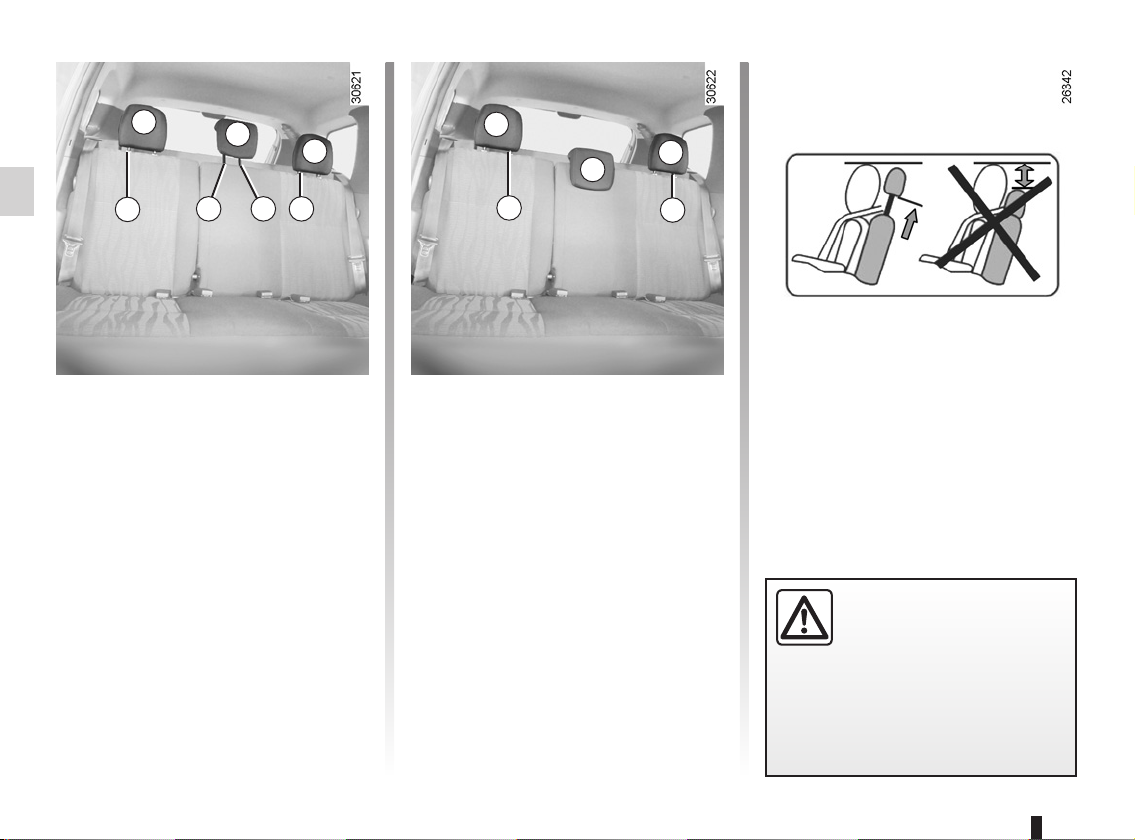
REAR HEADRESTS
A
B
A
1
Adjusting the height of the
headrests A
Press lock tab 1 and simultaneously
slide the headrest to the required position.
To remove the headrests A
Press the tabs on the catches 1 and 4
and remove the headrest.
To remove headrest B
(depending on vehicle)
Simultaneously press the tabs on
catches 2 and 3 on each of the headrest rods, then remove the headrest.
2 3 1
A
A
B
4
Position for using headrest B
(depending on vehicle)
Raise the headrest until it locks to use
it in the high position. Simultaneously
press the tabs on catches 2 and 3 and
lower the headrest completely.
Storage position for headrest B
(depending on vehicle)
When the headrest is set at the
lowest position, this is for storage
only. It should not be in this position
when a seat is occupied.
4
To reinstall headrests A
and B (depending on the
vehicle)
Insert the rods into the holes, press the
tabs on both rods and lower the headrest.
The headrest is a safety
component. Ensure that it is
fitted and in the correct po-
sition: the top of your head
should be in line with the top of the
headrest.
1.10
Page 17
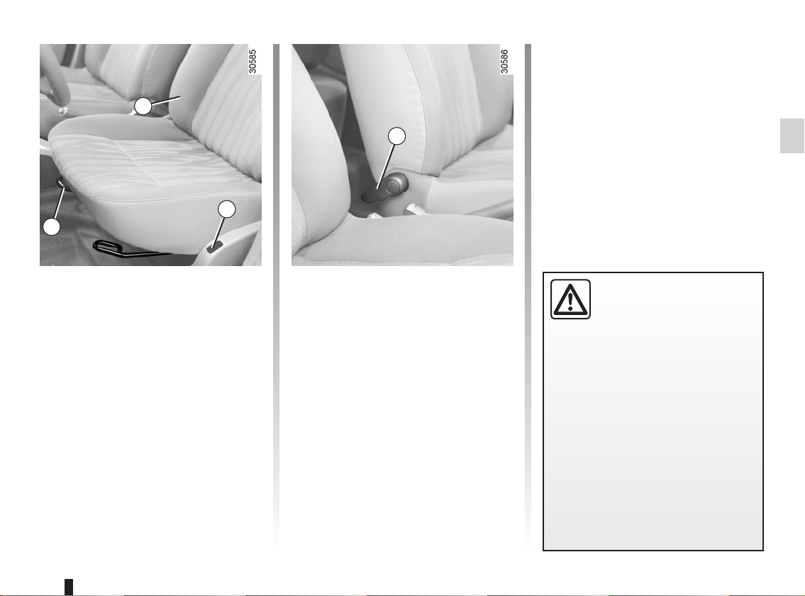
FRONT SEATS
2
1
4
3
To move forwards or
backwards
Lift bar 1 to release. Release the bar
once the seat is in the correct position
and ensure that the seat is fully locked
into position.
To raise or lower the driver’s
seat surface
Depending on the vehicle, lift lever 2,
adjust the seat base to the desired
height, then release the lever.
Heated seats
Depending on the vehicle, with the ignition on, press switch 3.
The system, which has a thermostat,
decides whether or not the heating is
needed.
To tilt the seatback
Depending on the vehicle, move the
handle or control knob 4 and tilt the
seatback to the desired position.
For safety reasons, carry
out any adjustments when
the vehicle is not being
driven.
We would advise you not to recline
the seatbacks too far to ensure that
the effectiveness of the seat belts is
not reduced.
Make sure that the seatbacks are
correctly locked in place.
Nothing should be placed on the
floor (area in front of driver) as such
objects may slide under the pedal
during braking manoeuvres, thus
obstructing its use.
1.11
Page 18
SEAT BELTS (1/4)
Always wear your seat belt when travelling in your vehicle. You must also
comply with the legislation of the particular country you are in.
Make sure that the rear bench seat
is locked in position correctly so that
the rear seat belts will operate efficiently. Refer to the information on
the “Rear bench seat: functions” in
Section 3.
Incorrectly adjusted or
twisted seat belts may
cause injuries in the event
of an accident.
The seatbelt is for the use of one
person only, whether adult or child.
Even pregnant women should wear
a seat belt. In this case, ensure that
the lap belt is not exerting too much
pressure on the abdomen, but do
not allow any slack.
Before starting, adjust your driving
position and then have each occupant adjust their seat belt to ensure
optimum protection.
Adjusting your driving position
(depending on the vehicle)
– Sit well back in your seat (having
removed your coat or jacket etc.).
This is essential to ensure your back
is positioned correctly;
– adjust the distance between the
seat and the pedals. Your seat
should be as far back as possible
while still allowing you to depress
the clutch pedal fully. The seatback
should be adjusted so that your arms
are slightly bent when you hold the
steering wheel;
– adjust the position of your head-
rest. For the maximum safety, your
head must be as close as possible to
the headrest;
– adjust the height of the seat. This
adjustment allows you to select the
seat position which offers you the
best possible view;
– adjust the position of the steering
wheel.
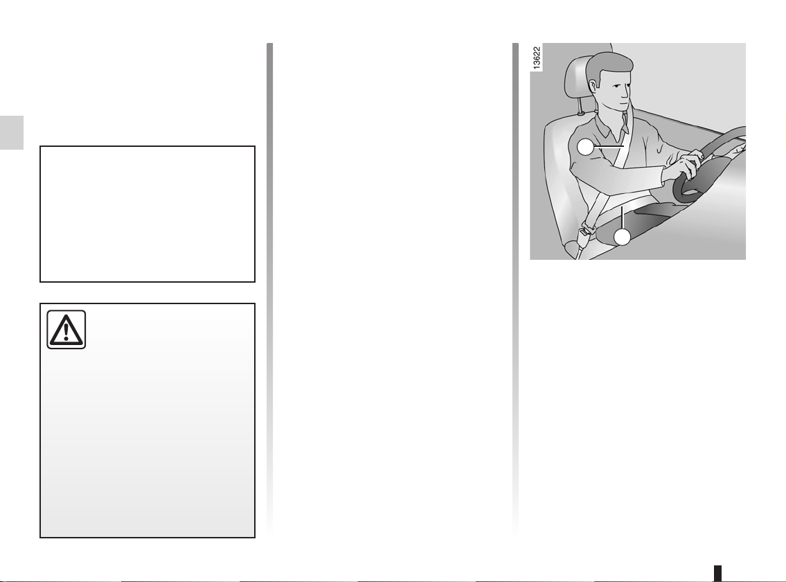
1
2
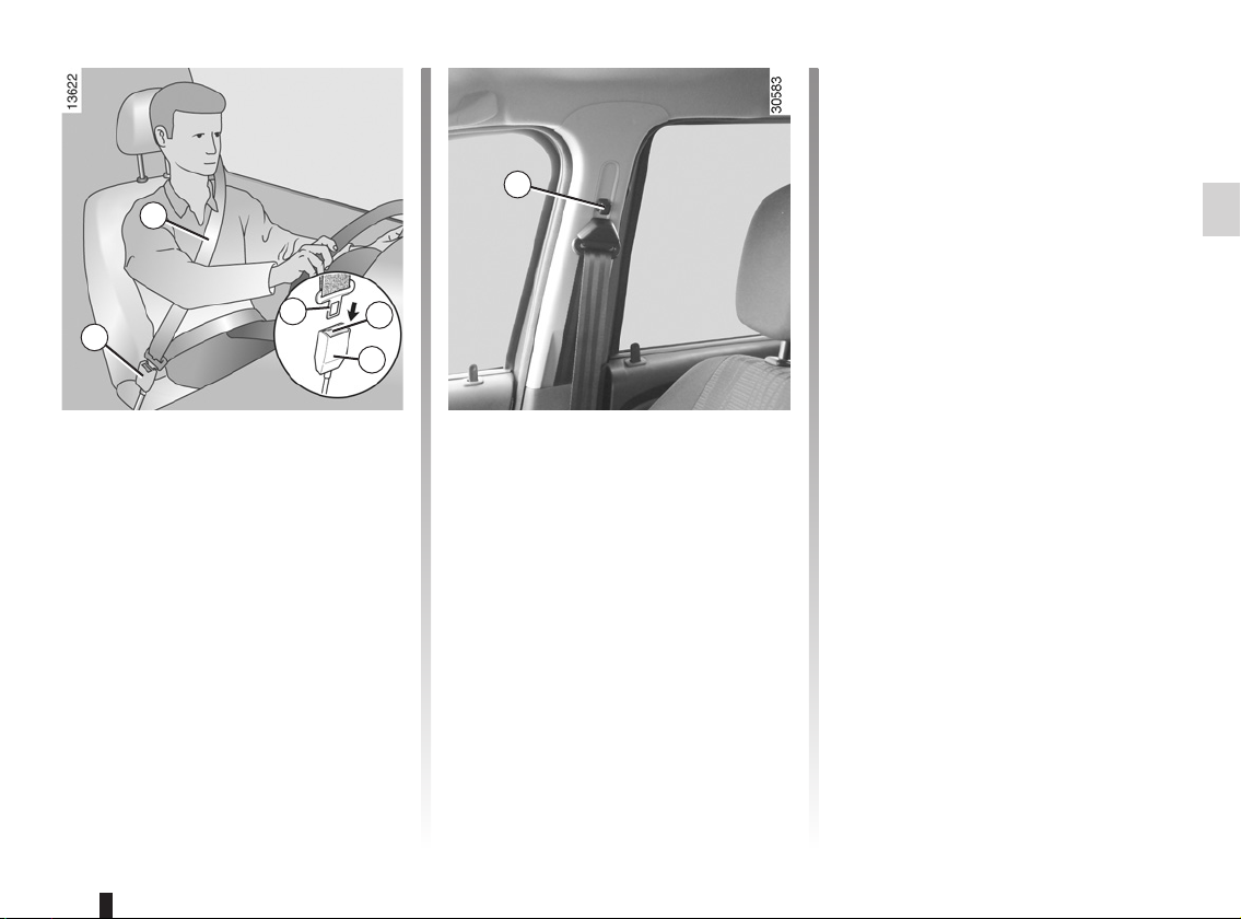
Adjusting the seat belts
Sit with your back firmly against the
seatback.
Shoulder strap 1 should be as close as
possible to the base of the neck but not
on it.
Lap belt 2 must be worn flat over the
thighs and against the pelvis. The seat
belt must be worn as close to the body
as possible. i.e.: avoid wearing heavy
clothing or keeping bulky objects under
the belts, etc.
1.12
Page 19
SEAT BELTS (2/4)
3
Seat belt reminder light
ß
Depending on the vehicle, it
comes on when the engine is started
if the driver’s seat belt is not fastened.
7
When the vehicle is being driven, it
comes on and a beep sounds for approximately 2 minutes until the driver’s
seat belt is fastened.
4
5
6
6
To fasten
Unwind the belt slowly and smoothly
and ensure that buckle 4 locks into
catch 6 (check that it is locked by pulling
on buckle 4). If it jams, allow it to return
before attempting to unwind it again. If
your seat belt is completely jammed,
pull slowly, but firmly so that just over
3 cm unwinds. Allow it to return slightly
before attempting to unwind it again.
If there is still a problem, contact an approved dealer.
Unlocking
Press button 5 on catch 6; the seat belt
is wound up by the inertia reel. Guide
the buckle to facilitate this manoeuvre.
Adjusting the front seat belt
height
(depending on the vehicle)
Move button 7 to select the position you
require so that chest strap 3 is worn as
described above.
Make sure that the seat belt is locked
in position correctly after you have adjusted it.
1.13
Page 20
SEAT BELTS (3/4)
A
A
9
8
10
10
9
8
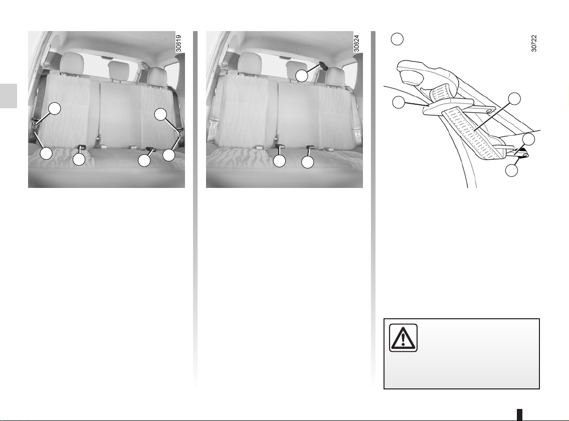
Rear side seat belts
Slowly unwind belt 8 and click buckle 9
into red catch 10.
11
12
Rear centre seat belt A
(depending on vehicle)
Remove buckle 15 from its housing 16.
Slowly unwind belt 14 and click
buckle 15 into black catch 12.
Fasten sliding buckle 13 into red
catch 11.
Insert buckle 15 into housing 16 when-
ever the seat belt is not in use.
13
Check that the rear seat
belts are positioned and operating correctly each time
the rear seats are moved.
14
15
16
1.14
Page 21
SEAT BELTS (4/4)
The following information applies to the vehicle’s front and rear seat belts.
– No modification may be made to the component parts of the restraint system (belts and seats and their mountings)
fitted originally. For special operations (e.g. fitting child seats) contact an approved Dealer.
– Do not use devices which allow any slack in the belts (e.g. clothes pegs, clips, etc.): a seat belt which is worn too
loosely may cause injury in the event of an accident.
– Never wear the shoulder strap under your arm or behind your back.
– Never use the same belt for more than one person and never hold a baby or child on your lap with your seat belt around
them.
– The belt should never be twisted.
– Following an accident, have the seat belts checked and replaced if necessary. Always replace your seat belts as soon as
they show any signs of wear.
– Make sure that the buckle is inserted into the appropriate catch.
– Ensure that no objects are placed in the area around the seat belt catch as they could prevent it from being properly se-
cured.
1.15
Page 22
METHODS OF RESTRAINT IN ADDITION TO THE FRONT SEAT BELTS (1/3)
Depending on the vehicle, they are
composed of:
– seat belt pretensioners;
– chest-level load limiters;
– air bags for the driver and front pas-
senger.
These systems are designed to act independently or together when the vehicle is subjected to a frontal impact.
Depending on the severity of the
impact, the system can trigger:
– seat belt locking;
– the seat belt pretensioner to hold the
occupant in the seat, and the force
limiter;
– the front air bag.
Pretensioner
With the ignition switched on, if the
vehicle is subject to a significant frontal impact the system may, depending
on the severity of the impact, trigger a
piston which instantly retracts the seat
belt.
The pretensioner holds the seat belt
against the body, holding the occupant
more securely against the seat, thus increasing the seat belt’s efficiency.
Load limiter
Above a certain level of impact force,
this mechanism is used to limit the force
of the belt against the body so that it is
at an acceptable level.
– Have the entire restraint
system checked following
an accident.
– No operation whatsoever
is permitted on any part of the
system (air bags, electronic control units, wiring) and the system
components must not be reused
on any other vehicle, even if identical.
– To avoid premature triggering
of the system which may cause
injury, only qualified Network personnel are authorisedto work on
the methods of restraint in addition to the front seat belt.
– The electric trigger system may
only be tested by a specially
trained technician using special
equipment.
– When the vehicle is scrapped,
contact an approved dealer for
disposal of the pretensioner and
airbag gas generators.
1.16
Page 23
METHODS OF RESTRAINT IN ADDITION TO THE FRONT SEAT BELTS (2/3)
Driver’s and passenger air
bags
These may be fitted to the front seats
on the driver and passenger side (location A).
Each air bag system consists of:
– an air bag and gas generator fitted
on the steering wheel for the driver
and in the dashboard for the front
passenger;
– an electronic unit for system monitor-
ing which controls the gas generator
electrical trigger system;
– a special warning light
– remote sensors.
å;
Operation
This system is only operational when
the ignition is switched on.
If a severe frontal impact occurs, the
air bag(s) inflate(s) rapidly, cushioning the impact of the driver’s head and
chest against the steering wheel and
the front passenger’s head against the
dashboard. The air bag then deflates
immediately so that the passengers are
not impeded in any way when they get
out of the vehicle.
A
The air bag system uses
pyrotechnic principles. This
explains why, when the air
bag inflates, it will gener-
ate heat, produce smoke (this does
not mean that a fire is about to start)
and make a noise upon detonation.
An air bag may inflate immediately,
causing some minor, superficial
grazing to the skin or other discomfort.
1.17
Page 24
METHODS OF RESTRAINT IN ADDITION TO THE FRONT SEAT BELTS (3/3)
All of the warnings below are given so that the air bag is not obstructed in any way when it is deployed and also to prevent the risk of serious injuries caused by items which may be dislodged when the air bag deploys.
Warnings concerning the driver’s air bag
– Do not modify the steering wheel or the steering wheel boss.
– Do not cover the steering wheel boss under any circumstances.
– You must not remove the steering wheel (such work must only be performed by trained personnel from our Network).
– When driving, do not sit too close to the steering wheel. Sit with your arms slightly bent (see the information on “Adjusting
Warnings concerning the passenger air bag
– Do not attach or glue any objects (badge, logo, clock, telephone holder, etc.) to the dashboard in the proximity of the air bag
– Do not place anything between the dashboard and the passenger (pet, umbrella, walking stick, parcels, etc.).
– The passenger must not put his or her feet on the dashboard or seat as there is a risk that serious injuries may occur. In
– You should reactivate the passenger air bag as soon as you remove the child seat to ensure the protection of the front pas-
– Do not attach any objects (badge, logo, clock, telephone holder, etc.) to the steering wheel boss.
your driving position” in Section 1). This will allow sufficient space for the air bag to inflate properly and be fully effective.
housing.
general, all parts of the body should be kept away from the dashboard (knees, hands, head etc.).
senger in the event of an impact.
A REAR-FACING CHILD SEAT MUST NOT BE FITTED TO THE FRONT PASSENGER SEAT UNLESS
THE RESTRAINT SYSTEMS IN ADDITION TO THE SEAT BELT, I.E. AIR BAG, ARE DEACTIVATED.
(refer to the information on “Child safety: deactivating/activating the front passenger air bag” in Section 1)
1.18
Page 25
SIDE PROTECTION DEVICES
Side air bags
These air bags may be fitted to the front
seats and are deployed at the sides of
the seats (door side) to protect the occupants in the event of a severe side
impact.
Warnings concerning the side air bag
– Fitting seat covers: seats equipped with an air bag require covers
specifically designed for your vehicle. Contact an approved dealer to find
out if such covers are available from our Network. The use of any covers
other than those designed for your vehicle (including those designed for another vehicle) may affect the operation of the air bags and reduce your protection.
– Do not place any accessories, objects, or even pets, between the seatback,
the door and the internal fittings. Do not cover the seatback with objects such
as clothes or accessories. This may prevent the air bag from operating correctly or cause injury when the air bag is deployed.
– No work or modification whatsoever may be carried out on the seat or internal
fittings, except by qualified personnel from our Network.
1.19
Page 26
ADDITIONAL METHODS OF RESTRAINT
All of the warnings below are given so that the air bag is not obstructed in any
way when it is inflated and also to prevent the risk of serious injuries caused
by items which may be dislodged when the air bag inflates.
The airbag is designed to complement the action of the seat belt. Both the
airbags and seat belts are integral parts of the same protection system.
It is therefore essential to wear the seat belt at all times. If seat belts are
not worn, the occupants are exposed to the risk of serious injury in the
event of an accident. It may also increase the risk of minor superficial injuries
occurring when the airbag is deployed, although such minor injuries are always
possible with airbags.
If the vehicle should overturn or suffer a rear impact, however severe, the pretensioners and air bags are not always triggered. Impacts to the underside of the
vehicle, e.g. from pavements, potholes or stones, can all trigger these systems.
– No work or modification whatsoever may be carried out on any part of the
driver or passenger air bag system (air bag, electronic unit, wiring, etc.), except
by qualified personnel from our Network.
– To ensure that the system is in good working order and to avoid accidental trig-
gering of the system which could cause injury, only qualified personnel from
our Network may work on the air bag system.
– As a safety precaution, have the air bag system checked if your vehicle has
been involved in an accident, or is stolen or broken into.
– When selling or lending the vehicle, inform the user of these points and hand
over this driver’s handbook with the vehicle.
– When scrapping your vehicle, contact your approved Dealer for disposal of the
gas generator(s).
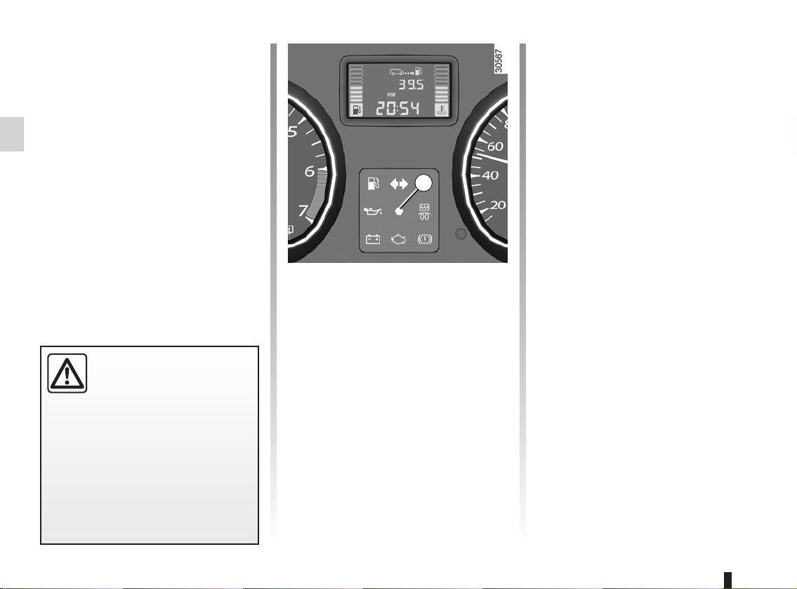
1
Operating faults
Indicator light 1, å, lights up when
the ignition is switched on and goes out
after a few seconds.
If it does not light up when the ignition
is switched on, or if it lights up when the
engine is running, it indicates a fault in
the system. In this case, fitting a child
seat in the front passenger seat is
PROHIBITED.
Contact an approved dealer as soon
as possible. Your protection will be reduced until this fault is rectified.
1.20
Page 27
CHILD SAFETY: General information (1/2)
Carrying children
Children, and adults, must be correctly
seated and strapped in for all journeys.
The children being carried in your vehicle are your responsibility.
A child is not a miniature adult. Children
are at risk of specific injuries as their
muscles and bones have not yet finished growing. The seat belt alone
would not provide suitable protection.
Use an approved child seat and ensure
you use it correctly.
A collision at 30 mph
(50 km/h) is the same as falling a distance of 10 metres.
Transporting a child without
To prevent the doors being
opened, use the childproof
locks (refer to the informa-
tion on “Locking/unlocking
the doors” in Section 1).
a restraint is the equivalent of allowing him or her to play on a fourthfloor balcony without railings.
Never travel with a child held in your
arms. In the event of an accident,
you will not be able to keep hold of
the child, even if you yourself are
wearing a seat belt.
If your vehicle has been involved in
a road accident, replace the child
seat and have the seat belts and
ISOFIX fittings checked.
Never leave a child unattended in the vehicle.
Check that your child is
always strapped in and that
the belt or safety harness used is
correctly set and adjusted. Avoid
wearing bulky clothing which could
cause the belts to slacken.
Never let your child put their head or
arms out of the window.
Check that the child is in the correct
position for the entire journey, especially if asleep.
1.21
Page 28
CHILD SAFETY: General information (2/2)
Using a child seat
The level of protection offered by the
child seat depends on its ability to restrain your child and on its installation.
Incorrect installation compromises the
protection it offers the child in the event
of harsh braking or an impact.
Before purchasing a child seat, check
that it complies with the regulations for
the country you are in and that it can
be fitted in your vehicle. Consult an approved dealer to find out which seats
are recommended for your vehicle.
Before fitting a child seat, read the
manual and respect its instructions. If
you experience any difficulties during
installation, contact the manufacturer
of the equipment. Keep the instructions
with the seat.
Set a good example by always fastening your seat belt and teaching
your child:
– to strap themselves in correctly;
– to always get in and out of the car
at the kerb, away from busy traffic.
Do not use a second-hand child
seat or one without an instruction
manual.
Check that there are no objects in
the vicinity of the child seat which
could impede its operation.
Never leave a child unattended in the vehicle.
Check that your child is
always strapped in and that
the belt or safety harness used is
correctly set and adjusted. Avoid
wearing bulky clothing which could
cause the belts to slacken.
Never let your child put their head or
arms out of the window.
Check that the child is in the correct
position for the entire journey, especially if asleep.
1.22
Page 29
CHILD SAFETY: choosing a child seat
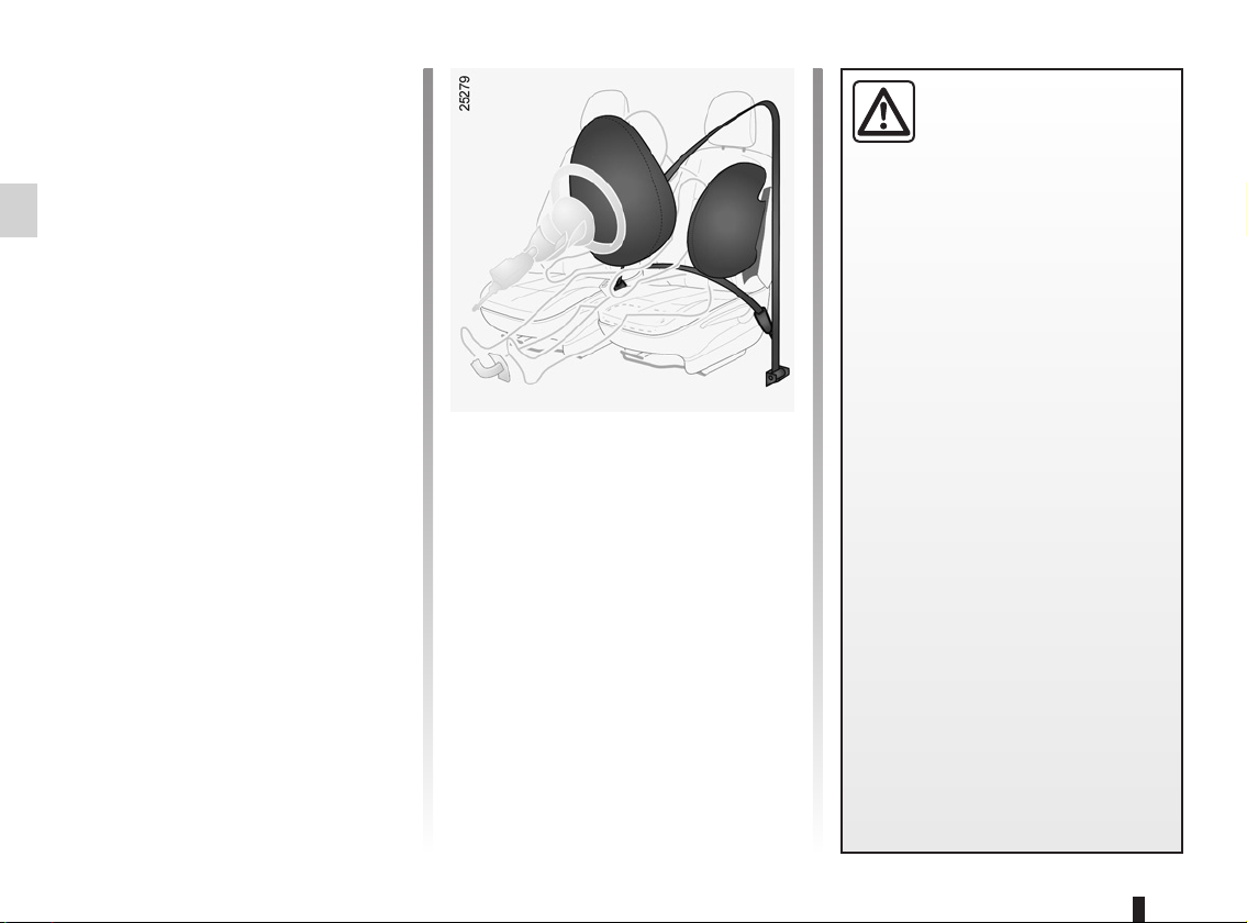
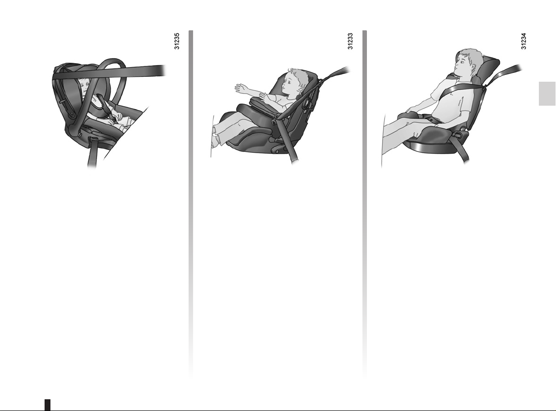
Rear-facing child seats
A baby’s head is, proportionally, heavier
than that of an adult and its neck is very
fragile. Transport the child in this position for as long as possible (until the
age of 2 at the very least). It supports
the head and neck. Choose a bucket
type seat for better side protection and
replace it as soon as the child’s head
extends past the seat shell.
Forward-facing child seats
The child’s head and abdomen need to
be protected as a priority. A forward-facing child seat which is firmly attached to
the vehicle will reduce the risk of impact
to the head. Transport your child in a
forward-facing seat with a safety harness or guard depending on the child’s
size. Choose a bucket type seat for
better side protection.
Booster cushions
From 15 kg or 4 years, the child can
travel using a booster seat, which will
enable the seat belt to be adapted
to suit his/her size and shape. The
booster seat cushion must be fitted with
guides to position the seat belt on the
child’s thighs rather than the stomach.
It is recommended that you use a seatback fitted with a belt strap guide which
can be adjusted in terms of height to
position the seat belt in the centre of
the shoulder. It should never rest on the
neck or over the arm. Choose a bucket
type seat for better side protection.
1.23
Page 30
CHILD SAFETY: mounting a child seat (1/2)
Attachment via the seat belt
The seat belt must be adjusted to
ensure that it is effective in the event of
harsh braking or an impact.
Ensure that the strap paths indicated
by the child seat manufacturer are respected.
Always check that the seat belt is correctly fastened by pulling it up, then
pulling it out fully whilst pressing on the
child seat.
Check that the seat is correctly held by
moving it from side to side and back
to front: the seat should remain firmly
fixed.
Check that the child seat has not been
installed at an angle and that it is not
resting against a window.
Do not use the child seat
if it may unfasten the seat
belt restraining it: the base
of the seat must not rest on
the buckle and/or catch of the seat
belt.
The seat belt must never
be twisted or the tension
relieved. Never pass the
shoulder strap under the
arm or behind the back.
Check that the seat belt has not
been damaged by sharp edges.
If the seat belt does not operate normally, it will not protect the child.
Consult an approved dealer. Do not
use this seat until the seat belt has
been repaired.
No modifications may be
made to the component
parts of the restraint system
(seat belts, ISOFIX, seats
and their mountings) originally fitted.
Attachment with the ISOFIX system
Authorised ISOFIX child seats are approved in accordance with regulation
ECE-R44 in one of the three following
cases:
– ISOFIX universal 3-point forward-
facing seat;
– ISOFIX semi-universal 2-point seat;
– specific.
For the latter two, check that your child
seat can be installed by consulting the
list of compatible vehicles.
Attach the child seat with the ISOFIX
locks, if these are provided. The ISOFIX
system allows quick, easy, safe fitting.
The ISOFIX system is composed of
2 rings for each rear side seat.
Before using an ISOFIX
child seat that you purchased for another vehicle,
check that its installation is
authorised. Consult the list of vehicles which can be fitted with the
seat from the equipment manufacturer.
1.24
Page 31

CHILD SAFETY: mounting a child seat (2/2)
1
2
The rings ISOFIX 1 are located between the seatback and the seat base
and are clearly visible.
To ensure your child seat can be easily
fitted and locked on rings 1, use access
guides 2 on the child seat.
The ISOFIX anchorage points have been exclusively designed for child
seats with the ISOFIX system. Never fit a different type of child seat, seat
belt or other objects to these anchorage points.
Check that nothing is obstructing the anchorage points.
If your vehicle has been involved in a road accident, have the ISOFIX anchorage
points checked and replace your child seat.
The third ring of each side seat is used
to attach the upper strap on some child
seats.
Pass the belt between the seatback
and the luggage compartment cover.
3
4
Attach the hook on the belt to one of the
rings 3 (4x2 version) or 4 (4x4 version).
Pull the belt so that the back of the child
seat comes into contact with the vehicle
seatback.
It is essential to use the lug-
gage compartment anchor-
age points 3 or 4 to attach
the upper belt of the child
seat.
It is forbidden to use other mounting
points to attach this strap.
1.25
Page 32

CHILD SAFETY: fitting a child seat (1/6)
Some seats are not suitable for fitting
child seats. The diagram on the following page shows you how to attach a
child seat.
The types of child seats indicated may
not be available. Before using a different child seat, check with the manufacturer that it can be fitted.
Fit the child seat in a rear
seat wherever possible.
Check that when installing
the child seat in the vehicle
it is not at risk of coming loose from
its base.
If you have to remove the headrest,
check that it is correctly stored so
that it does not come loose under
harsh braking or impact.
Always attach the child seat to the
vehicle even if it is not in use so that
it does not come loose under harsh
braking or impact.
In the front seat
The laws concerning children travelling in the front passenger seat differ in
every country. Consult the legislation in
force and follow the indications on the
diagram on the following page.
Before fitting a child seat in this seat (if
authorised):
– deactivate the front passenger air
bag;
– lower the seat belt as far as possible;
– move the seat as far back as possi-
ble;
– gently tilt the seatback away from
vertical (approximately 25°).
Do not change these settings after the
child seat is installed.
RISK O F DEATH OR
SERIOUS INJURY: before
fitting a child seat in this
seat, check that the air bag
has been deactivated (refer to the information on “Deactivating the front
passenger air bag” in Section 1).
1.26
Page 33

CHILD SAFETY: fitting a child seat (2/6)
In the rear side seat
A carrycot can be installed across the
vehicle and will take up at least two
seats. Position the child with his or her
feet nearest the door.
Before installing a child seat in the
ISOFIX anchoring points on a rear side
seat, check that the seat belt buckles
are not placed between the two ISOFIX
anchorage points in this seat. If necessary, move the buckle for the seat concerned towards the centre of the vehicle.
Move the front seat as far forward as
possible to install a rear-facing child
seat, then move back the seat in front
as far as it will go, although without allowing it to come into contact with the
child seat.
For the safety of the child in the forward-facing seat, do not move the seat
in front back past the middle of the
runner, do not tilt the seatback too far
(maximum of 25°) and raise the seat as
much as possible.
Check that the forward-facing child seat
is resting against the back of the vehicle seat and that the headrest of the vehicle is not obstructing its use.
Make sure that the child
seat or the child’s feet do
not prevent the front seat
from locking correctly.
Please refer to the information on
the “Front seat” in Section 1.
Rear centre seat
A child seat may only be fitted in this
seat if it is equipped with an inertia-reel
belt. For any additional information,
contact an approved dealer.
1.27
Page 34

CHILD SAFETY: fitting a child seat (3/6)
Vehicles without air bag OR with air bag deactivated
³ Check the status of the air bag
before fitting a child seat or allowing a
passenger to use the seat.
RISK O F DEATH OR
SERIOUS INJURY: before
installing a child/baby seat
on the front passenger seat,
check that the air bag has been deactivated (refer to “Deactivating the
front passenger air bag” at the end
of the paragraph).
² Seat not suitable for fitting child
seats.
¬ Seat which allows a child seat
with “Universal” approval to be attached
by a seat belt.
− Seat which only allows a rear-
facing seat with “Universal” approval
to be attached with a seat belt.
Only if the seat is equipped with an
1
inertia-reel belt.
Child seat attached using the ISOFIX
mounting
ü Seat which allows an ISOFIX
child seat to be fitted.
± The rear seats are fitted with
an anchorage point which allows a
forward-facing ISOFIX child seat with
universal approval to be fitted. The anchorage points are located under the
luggage compartment carpet and are
indicated by a marking.
The size of the ISOFIX child seat is indicated by a letter:
– A, B and B1: for forward-facing seats
in group 1 (9 to 18 kg);
– C: rear-facing seats in group 1 (9 to
18 kg);
– D and E: shell seat or rear-facing
seats in group 0 or 0+ (less than
13 kg);
– F and G: cots in group 0 (less than
10 kg).
Using a child safety system
which is not approved for
this vehicle will not correctly
protect the baby or child.
They risk serious or even fatal injury.
1.28
Page 35

CHILD SAFETY: fitting a child seat (4/6)
Vehicles with passenger air bag not deactivated
Child seat attached using the belt
² Seat not suitable for fitting child
seats.
RISK O F DEATH OR
SERIOUS INJURY: never
fit a child seat to this seat.
¬ Seat which allows a child seat
with “Universal” approval to be attached
by a seat belt.
Only if the seat is equipped with an
1
inertia-reel belt.
Child seat attached using the ISOFIX
mounting
ü Seat which allows an ISOFIX
child seat to be fitted.
± The rear seats are fitted with
an anchorage point which allows a
forward-facing ISOFIX child seat with
universal approval to be fitted. The anchorage points are located under the
luggage compartment carpet and are
indicated by a marking.
The size of the ISOFIX child seat is indicated by a letter:
– A, B and B1: for forward-facing seats
in group 1 (9 to 18 kg);
– C: rear-facing seats in group 1 (9 to
18 kg);
– D and E: shell seat or rear-facing
seats in group 0 or 0+ (less than
13 kg);
– F and G: cots in group 0 (less than
10 kg).
Using a child safety system
which is not approved for
this vehicle will not correctly
protect the baby or child.
They risk serious or even fatal injury.
1.29
Page 36

CHILD SAFETY: fitting a child seat (5/6)
The table below summarises the information already shown on the diagram on the previous pages, to ensure the regulations in force are respected.
Type of child seat
Carrycot fitted across the
vehicle
Approved for group 0
Front passenger
Weight of
the child
< 10 kg F - G X X
Seat
size
seat without air
bag or with air
bag deactivated
(1) (5)
Front passenger
seat with air bag
without deactivation
(1) (6)
Rear
side
seats
U-IL
(2)
Rear centre
seat
(7)
U
Rear-facing shell seat
Approved for group 0 or 0+
Rear-facing seat
Approved for group 0+ and 1
Forward-facing seat
Approved for group 1
Booster seat
Approved for group 2 and 3
(5) RISK OF DEATH OR SERIOUS INJURY: before fitting a child seat on the front passenger seat, check that the air
bag has been deactivated (refer to the information on “Deactivating the front passenger air bag” in Section 1).
(6) RISK OF DEATH OR SERIOUS INJURY: never fit a child seat to this seat.
1.30
< 13 kg
9 to 18 kg
9 to 18 kg C U X
9 to 18 kg
15 kg to 25
kg and
22 to 36 kg
D, E U X
A, B,
B1
– X X
X X
U-IL
(3)
U-IL
(3)
U - IUF
- IL
(4)
U
(4)
U
U
U
U
Page 37

CHILD SAFETY: fitting a child seat (6/6)
X = Seat not suitable for fitting child seats.
U = Seat which allows a child seat with “Universal” approval to be installed using a seat belt; check that it can be fitted.
IUF = Seat which, on equipped vehicles, allows forward-facing child seats with “Universal” approval to be attached by the ISOFIX
system: check that it can be fitted.
IL = On equipped vehicles, seat which allows an approved “semi-universal” or “vehicle specific” child seat to be attached using the
ISOFIX system; check that it can be fitted.
Refer to the brochure “Child safety equipment” available from the Network to choose the seat suited to your child and
recommended for your vehicle.
(1) Only a rear-facing child seat can be fitted in this seat: raise the seat to the maximum and position it as far back as possible,
tilting the seatback slightly (approximately 25°).
(2) A carrycot can be installed across the vehicle and will take up two seats. Position the child with his or her feet nearest the door.
(3) Move the front seat as far forward as possible to install a rear-facing child seat, then move back the seat in front as far as it will
go, although without allowing it to come into contact with the child seat.
(4) Forward-facing child seat; position the seatback of the child seat in contact with the seatback of the vehicle seat. Adjust the
headrest, or remove it if necessary. Do not push the seat in front of the child more than halfway back on its runners and do not
recline the seatback more than 25°.
(7) A child seat may only be fitted in this seat if it is equipped with an inertia-reel seat belt. For any additional information, please
contact an authorised dealer.
1.31
Page 38

CHILD SAFETY: deactivating/activating the front passenger air bag (1/3)
1
Deactivating the front
passenger air bag
(depending on vehicle)
To fit a rear-facing child seat on the
front passenger seat, you must deactivate the front passenger air bag if your
vehicle is fitted with air bag deactivation.
2
2
To deactivate the passenger airbag,
with the ignition off, press and turn
button 1 to the OFF position.
With the ignition switched back on, it is
essential to check that warning light 2,
], is lit up on the instrument panel.
This warning light remains continuously lit to let you know that you can
fit a child seat.
1.32
Page 39

CHILD SAFETY: deactivating/activating the front passenger air bag (2/3)
3
DANGER
Since front passenger air
The passenger air bag must
be activated or deactivated
with the ignition off.
If handled when the igni-
tion is on, the warning light
comes on.
Switch the ignition off then on again
to reset the air bag in accordance
with the lock position.
å
seat are incompatible, it is not permitted to fit such a seat in this position unless the vehicle is fitted with an
air bag deactivation device. The child
may suffer very serious injuries if the
air bag inflates.
The markings on the dashboard and
on each side of passenger sun visor 3
will remind you of these instructions.
bag triggering and the position of a rear-facing child
1.33
Page 40

CHILD SAFETY: deactivating/activating the front passenger air bag (3/3)
Activation of the front
passenger air bag
(depending on vehicle)
You should reactivate the airbag as
soon as you remove the child seat from
the front passenger seat to ensure the
protection of the front passenger in the
event of an impact.
To reactivate the airbag: with the vehicle at a standstill and with the ignition
switched off, press and turn button 1 to
the ON position.
With the ignition switched on, it is es-
sential to check that warning light 2,
], is off.
1.34
2
Operating faults
It is forbidden to fit a rear-facing child
seat to the front passenger seat if the
air bag activation/deactivation system
is faulty.
Allowing any other passenger to sit in
that seat is not recommended.
Contact your approved dealer as soon
as possible.
2
Page 41

REAR VIEW MIRRORS
0
B
2
A
1
Door mirrors with electrical
adjustment:
With the ignition on, move button 1:
– position A to adjust the left-hand
door mirror;
– position B to adjust the right-hand
door mirror;
0 is the neutral centre position.
Heated door mirrors
The mirror is de-iced when the rear
screen is de-iced/demisted; refer to
the information on the “Heated rear
screen”.
Door mirrors with manual
adjustment
To adjust the mirror, move lever 2.
Folding door mirrors
Manually fold the mirror in the direction
of the arrows.
3
Interior rear view mirror
Its position can be adjusted. When driving at night, to avoid being dazzled by
the headlights of the vehicle behind,
depress the little lever located behind
the rear view mirror 3.
1.35
Page 42

DRIVING POSITION, LEFT-HAND DRIVE (1/4)
The fittings described DEPEND ON THE VEHICLE VERSION AND COUNTRY
1
33
32
2
31
3
30
4
29
28
5
6
7
27
26
9
8
24
10
23
22
21
11
20
18
19
12
17
16
25
13
15
14
1.36
Page 43

DRIVING POSITION, LEFT-HAND DRIVE (2/4)
The fittings described DEPEND ON THE VEHICLE VERSION AND COUNTRY.
1 Side air vent.
2 Stalk for:
– direction indicator lights,
– exterior lights,
– front fog lights,
– rear fog light,
– horn.
3 Instrument panel.
4 Location for driver’s air bag.
5 Windscreen demister outlet.
6 Steering column stalk for wind-
screen and rear screen wash/wipe.
Information readout control.
7 Ignition switch.
8 Radio remote control.
9 Centre air vents.
10 Seat belt reminder light.
Front passenger airbag deactivation warning light.
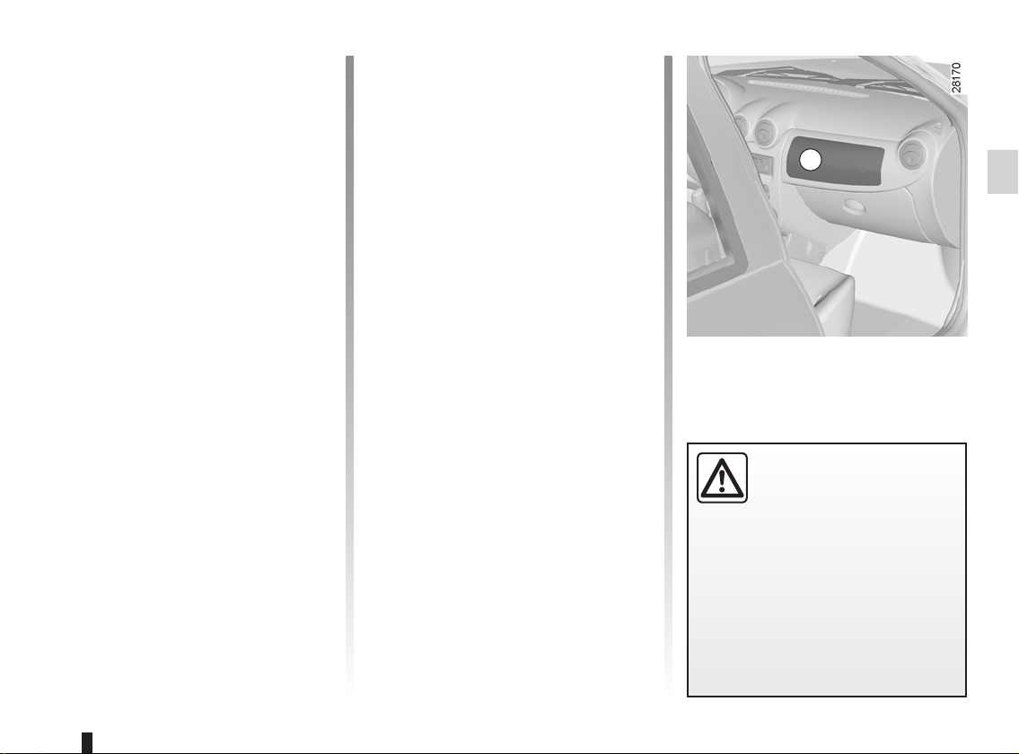
11 Location for passenger air bag or
storage compartment.
12 Side window demister.
13 Front passenger air bag activation/
deactivation lock.
14 Glove box.
15 Location for radio or storage com-
partment.
16 Electric front window control.
17 Central window electric locking
control.
18 Hazard warning lights switch.
19 Rear window electric locking con-
trol.
20 ESP control (4x4 version (4WD))
or blanking cover.
21 Cigar lighter or accessories socket.
22 Location for ashtray or cup holder.
23 4x2 (2WD) and 4x4 (4WD) mode
selector or storage compartment.
24 Handbrake.
25 Electric rear-view mirror control.
26 Electric rear window control.
27 Bottle holder
28 Gear lever.
29 Heating and ventilation controls.
30 Heated rear screen control.
31 Headlight beam height adjustment
control.
32 Bonnet release.
33 Fuse box.
1.37
Page 44

DRIVING POSITION, LEFT-HAND DRIVE (3/4)
The fittings described DEPEND ON THE VEHICLE VERSION AND COUNTRY
1
30 29
2
28
3
27
26
4
5
6
7
9
8
10
11
25
23
22
21
20
19
18
17
12
16
13
15
14
24
1.38
Page 45

DRIVING POSITION, LEFT-HAND DRIVE (4/4)
The fittings described DEPEND ON THE VEHICLE VERSION AND COUNTRY.
1 Side air vent.
2 Stalk for:
– direction indicator lights,
– exterior lights,
– front fog lights,
– rear fog light,
– horn.
3 Instrument panel.
4 Location for driver’s air bag.
5 Windscreen demister outlet.
6 Steering column stalk for wind-
screen and rear screen wash/wipe.
Information readout control.
7 Ignition switch.
8 Radio remote control.
9 Centre air vents.
10 Seat belt reminder light.
Front passenger airbag deactivation warning light.
11 Location for passenger air bag or
storage compartment.
12 Side window demister.
13 Front passenger air bag activation/
deactivation lock.
14 Glove box.
15 Location for radio or storage com-
partment.
16 Hazard warning lights switch.
17 Heated rear screen control.
18 Rear window electric locking con-
trol.
19 ESP control or blanking cover.
20 Cigarette lighter or accessories
socket.
21 Location for ashtray or cup holder.
22 Mode selector 4x2 (2WD), 4x4
(4WD) or storage compartment.
23 Handbrake.
24 Electric rear-view mirror control.
25 Gear lever.
26 Heating and ventilation controls.
27 Electric central locking switch.
28 Beam height adjustment control.
29 Bonnet release control.
30 Fuse box.
1.39
Page 46

WARNING LIGHTS (1/4)
The presence and operation of the warning lights DEPEND ON THE EQUIPMENT AND COUNTRY.
A
Warning lights on instrument
panel A
These warning lights require you to
stop immediately, for your own safety,
as soon as traffic conditions allow.
Switch off the engine and do not restart it. Contact an approved dealer.
Ú À Ô
D
+
x
#
This lights up on the instrument panel
when an oil change is required.
Change the oil or have it changed as
soon as possible.
Only the distance travelled between two
oil changes is taken into account; the
time interval between two oil changes
is not.
The oil should always be changed
when the first threshold is reached, i.e.
either the distance travelled or the interval specified in your vehicle’s maintenance document. This means you may
have to change the oil before the warning light comes on.
Refer to the information on the “Oil
change” in Section 4.
x
This light comes on when the ignition is
switched on and goes out within three
seconds. If it lights up when you are
driving, it indicates a fault in the antilock braking system.
Engine oil change warning
light
Anti-lock braking warning
light
Braking will then be as normal, without
the ABS.
Contact an approved dealer as soon as
possible.
k
á
å
engine is started and goes out after a
few seconds.
If it does not come on when the ignition is switched on, or comes on when
the engine is running, there is a fault in
the system.
Contact an approved dealer as soon as
possible.
Dipped beam headlight telltale light
Main beam headlight tell-tale
light
Air bag warning light
This comes on when the
If no lights or sounds are apparent, this indicates a fault
in the instrument panel. This
indicates that it is essential
to stop immediately (as soon as traffic conditions allow). Ensure that the
vehicle is correctly immobilised and
contact an approved Dealer.
1.40
Page 47

WARNING LIGHTS (2/4)
The presence and operation of the warning lights DEPEND ON THE EQUIPMENT AND COUNTRY.
’
Refer to the information on “4WD Lock
mode” in Section 2.
‘
Refer to the information on “2WD
mode” in Section 2.
V
L
neis started then goes out after three
seconds. If it stays on, fill up with fuel
assoon as possible.
d
Ô
This goes out as soon as the engine
starts. If it comes on when driving, it indicates an increase in the coolant temperature. Stop and let the engine idle
for a minute or two; the temperature
should fall.
4-wheel drive mode indicator light
2-wheel drive mode indicator light
Rear screen de-icing/demisting indicator light
Low fuel level warning light
It comes on when the engi-
Direction indicator tell-tale
light
Coolant temperature warning light
If not, switch off the engine and allow
it to cool before checking the coolant
level and the cleanliness of the radiator.
If the level is normal, this indicates another fault. Consult an approved dealer.
À
engine starts; if it lights up while driving, stop immediately and switch off the
ignition. Check the oil level.
If the level is normal, something else is
the cause. Contact an approved dealer.
ê
This light performs several functions.
Refer to the information on the “Engine
immobiliser” in Section 1.
6
this light comes on; it indicates that the
heater plugs are operating.
Oil pressure warning light
This goes out as soon as the
Engine immobiliser system
warning light
Electronic fault or diesel
preheating warning light
With the ignition switched on,
It goes out after preheating is sufficient
and the engine can be started.
If it remains lit or comes on when you
are driving, it indicates an electrical or
electronic fault. Contact an approved
dealer as soon as possible.
Ò
If it remains lit or comes on when you
are driving, it indicates an electrical or
electronic fault. Contact an approved
dealer as soon as possible.
Ú
engine starts.
If it comes on when you are driving, it
indicates that the circuit is overcharging
or has discharged. Stop and contact an
approved Dealer.
ù
“Electronic stability program (ESP) with
understeer control and traction control
(ASR)” in Section 2.
Electronic fault warn in g
light, petrol versions
Battery charge warning light
It should go out as soon as the
ESP warning light
Refer to the information on the
1.41
Page 48

WARNING LIGHTS (3/4)
The presence and operation of the warning lights DEPEND ON THE EQUIPMENT AND COUNTRY.
Ä
It comes on when the ignition is
switched on and then goes out.
– If it comes on continuously, consult
– If it flashes, reduce the engine speed
Refer to the information “Advice on
antipollution, fuel economy and driving”
in Section 2.
D
If it lights up, check that the hand brake
is fully released. If not, it indicates that
the fluid level is low in one of the circuits. It may be dangerous to continue
driving, contact an approved dealer.
Toxic Fume Filter System
Warning Light
an approved dealer as soon as possible.
until the light stops flashing. Contact
an approved dealer as soon as possible.
Handbrake on and brake circuit incident warning light
f
Æ
is switched on and goes out as soon as
the engine is started. It lights up at the
same time as other warning lights, and
is accompanied by a beep.
It requires you to stop immediately, for
your own safety, as soon as traffic conditions allow.
Switch off the engine and do not restart
it.
Consult an approved dealer.
g
^
If it remains lit or comes on while driving, it indicates that water is present in
the diesel filter. Contact an approved
dealer as soon as possible.
Å
This indicates the status of the doors
(or tailgate).
Rear fog light tell-tale
STOP light
This lights up when the ignition
Front fog light tell-tale
Water in the diesel filter
warning light
Door status warning light
Ü
î
Not used
Not used
1.42
Page 49

WARNING LIGHTS (4/4)
The presence and operation of the warning lights DEPEND ON THE EQUIPMENT AND COUNTRY.
B
Warning lights on console B
]
Refer to the information on “Child
Safety” in Section 1.
ß
This warning light comes on continuously on the centre console when the
engine is started. If one of the seat belts
affected is not fastened, the light stays
on then, when the vehicle reaches
a speed of approximately 6 mph
(10 km/h), it flashes and a beep sounds
for approximately 90 seconds.
Front passenger air bag deactivation warning light.
Front seat belt reminder
warning light
B
1.43
Page 50

DISPLAY AND INDICATORS (1/2)
1
2
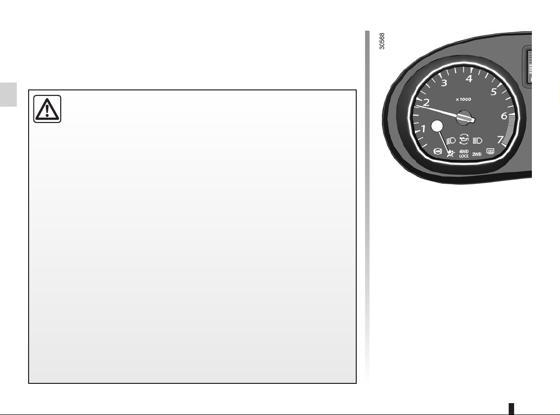
Rev counter 1 (rpm × 1 000) Speedometer 2 (km or miles
per hour)
Overspeed buzzer
Depending on the vehicle, a buzzer
sounds for approximately 10 seconds
every 30 seconds, as long as the vehicle is travelling in excess of 72 mph
(120 km/h).
3
Fuel gauge 3
The number of squares lit shows the
fuel level. When it is at minimum, the
squares disappear and the low fuel
level warning light comes on.
In 4x4 (4WD) mode on rough terrain, there is a risk that incorrect information on the fuel level may be
displayed. Wait until you are on flat
ground again for a stable reading of
the oil level squares.
1.44
Page 51

DISPLAY AND INDICATORS (2/2)
4
Multifunction key 5
A
5
– Display selection
By pressing the button you can shift
from the total mileage recorder, trip
mileometer and time or vice-versa.
– Resetting the trip mileage re-
corder
Once the trip mileage display is selected, press and hold the button.
– Resetting the clock
Refer to the information on the
“Clock” in Section 1.
Coolant temperature
indicator 4
The number of squares lit depends on
the engine coolant temperature. There
is no warning unless the last three
squares light up.
Multifunction display A
Total mileage recorder, distance travelled trip mileometer, clock.
OR
Trip computer and warning
system
Refer to the information on the “Trip
computer and warning system” in
Section 1.
1.45
Page 52

TRIP COMPUTER AND WARNING SYSTEM (1/4)
The information display DEPENDS ON THE VEHICLE EQUIPMENT AND COUNTRY.
1
3
2
Refer to the table on the following
pages showing display examples.
Display 1
General reset and trip
mileage recorder reset key 2
To reset the trip mileage recorder, the
display must show the Trip mileometer
function.
Press and hold button 2.
1.46
Display selection key 3
Keep pressing key 3 briefly to scroll
through the following information (depending on the vehicle) in sequence:
a) total mileage recorder,
b) trip mileage recorder,
c) fuel used,
d) average consumption,
e) estimated range,
f) distance travelled,
g) average speed.
Page 53

TRIP COMPUTER AND WARNING SYSTEM (2/4)
The information display DEPENDS ON THE VEHICLE EQUIPMENT AND COUNTRY.
Interpreting some of the
values displayed after
resetting
The values showing average fuel consumption, range and average speed
will become more stable and reliable
the further you travel after pressing the
reset button.
For the first few miles after pressing the
reset key you will notice that the range
increases as you travel. This range
takes into account the average fuel consumption since the last time the reset
button was pressed. Therefore, the fuel
consumption may decrease when:
– the vehicle stops accelerating,
– the engine reaches its operating
temperature (engine cold when
reset button pressed),
– when driving from a built-up area
onto the open road.
Therefore, if the average fuel con-
sumption decreases, the range
will increase.
– You may also notice that the aver-
age fuel consumption increases
when the vehicle is stationary and
the engine idling.
This is normal, since the computer
takes account of fuel used during
idling.
Manually resetting the journey parameters: with the display showing
one of the journey parameters, press
button 2 until the display is reset.
Automatically resetting the journey
parameters: the reset is automatic
when the capacity of one of the memories is exceeded.
1.47
Page 54

TRIP COMPUTER AND WARNING SYSTEM (3/4)
The information display DEPENDS ON THE VEHICLE EQUIPMENT AND COUNTRY.
Examples of display
selections by repeatedly
pressing 3
Interpreting the display
a) Total mileage recorder.
b) Trip mileage recorder.
c) Fuel used since the last time the reset button was pressed.
1.48
d) Average fuel consumption since the last time the reset button was pressed.
This value is displayed after driving 400 metres and takes into account the
distance travelled and the fuel used since the last time the reset button was
pressed.
Page 55

TRIP COMPUTER AND WARNING SYSTEM (4/4)
The information display DEPENDS ON THE VEHICLE EQUIPMENT AND COUNTRY.
Examples of display
selections by repeatedly
pressing 3
Interpreting the display
e) Estimated range with remaining fuel
This range takes into account the average fuel consumption since the last time
the reset button was pressed.
The value is displayed after driving around 400 metres.
f) Distance travelled since the last reset.
g) Average speed since the last reset.
The value is displayed after driving around 400 metres.
1.49
Page 56

STEERING WHEEL, POWER-ASSISTED STEERING
Power Assisted Steering
With the engine running, do not leave
the steering wheel at full lock while stationary as this may damage the power-
1
Adjusting the steering wheel
Depending on the vehicle, the steering
wheel position is adjustable.
Lift lever 1 and place the steering wheel
in the required position; raise the lever
to lock the steering wheel in place.
Make sure that the steering wheel is
correctly locked.
assisted steering pump.
With the engine switched off, or if there
is a system fault, it is still possible to
turn the steering wheel. The force required will be greater.
1.50
For safety reasons, only
adjust the steering wheel
when the vehicle is stationary.
Never switch off the ignition when travelling downhill, and avoid doing so in
normal driving (assistance
is not provided).
Page 57

CLOCK
1
2
Resetting the clock
With the ignition on, select display 1
showing total mileage and clock.
There are two ways to set the time:
– Pressing and holding button 2 allows
you to scroll through the hours and
minutes quickly;
– short presses on button 2 allow you
to set the time minute by minute.
If the electrical supply is cut (battery
disconnected, broken supply wire,
etc.), the clock will lose its time setting.
The clock must be reset.
For your safety, we recommend that you do not adjust
the clock while driving.
1.51
Page 58

AUDIBLE AND VISUAL SIGNALS (1/2)
1
2
Horn
Press the end of the stalk 1.
Depending on the vehicle, press on one
of areas 2.
Headlight flasher
Pull stalk 1 towards you to flash the
headlights.
1
Direction indicators
Move stalk 1 parallel to the steering
wheel and in the direction you are going
to turn it.
When driving on the motorway, the
steering wheel is not usually turned sufficiently to return the stalk automatically
to its starting position. There is an intermediate position in which the stalk may
be held when changing lanes.
When the stalk is released, it will automatically return to its starting position.
1.52
Page 59

AUDIBLE AND VISUAL SIGNALS (2/2)
3
Hazard warning lights
é
This switch activates all four direction
indicators and the side indicator lights
simultaneously.
It must only be used in an emergency to
warn drivers of other vehicles that you
have had to stop in an area where stopping is prohibited or unexpected, or that
you are obliged to drive under special
conditions.
Press switch 3.
3
1.53
Page 60

EXTERIOR LIGHTING AND SIGNALS (1/2)
1
u
symbol is opposite mark 2.
Side lights
Turn the end of stalk 1 until the
Before driving at night, check that the electrical equipment is operating
correctly and adjust the headlight beams (if your vehicle is not carrying
its normal load).
Check that the lights are not obscured (by dirt, mud, snow or objects
which could cover them).
1
k
Turn the end of stalk 1 until the symbol
is opposite mark 2.
An indicator light on the instrument
panel will come on.
Dipped beam
headlights
2
á
headlights position, move the stalk towards you.
When the main beam headlights are lit
up, an indicator light on the instrument
panel lights up.
To return to the dipped headlight position, pull the stalk towards you again.
e
initial position.
Lights-on warning buzzer
A warning buzzer will sound when a
front door is opened and the lights
are left on after the ignition has been
switched off (to prevent discharge of
the battery).
Main beam headlights
With stalk 1 in dipped beam
Switching off the lights
Return the end of stalk 1 to its
1.54
Page 61

EXTERIOR LIGHTING AND SIGNALS (2/2)
3
g
until the symbol is opposite mark 4.
The fog lights only light up if the exterior
lights have been switched on. An indicator light on the instrument panel then
lights up.
Do not forget to switch off the fog lights
when they are no longer needed, to
avoid inconveniencing other road
users.
Front fog lights
Turn the centre ring of stalk 3
3 4
h
stalk 3 until the symbol is opposite
mark 4.
The fog lights only light up if the exterior
lights have been switched on. An indicator light on the instrument panel then
lights up.
Remember to switch off the these
lights when they are no longer required
to avoid inconveniencing other road
users.
Rear fog lights
Turn the centre ring of
e
Turn centre ring 3 again until the symbol
for the fog light or for extinction position
is opposite mark 4.
The corresponding indicator light on the
instrument panel goes out.
The front and rear fog lights switch off
when the exterior lights are switched
off.
Turning off the fog
lights
1.55
Page 62

ADJUSTING THE BEAM HEIGHT
A
Examples of positions for adjusting control A according to the load
Driver alone or with front passenger 0
Control A is used to adjust the height
of the headlight beams according to the
load.
Turn control A anticlockwise to lower
the beams and clockwise to raise them.
1.56
Driver with one front passenger and
one rear passenger
Driver with one front passenger and
two rear passengers
Driver with one front passenger and
three rear passengers
Driver with one front passenger,
three rear passengers and luggage
Driver with one front passenger and
luggage
0
1
1
2
3
Page 63

WINDSCREEN WASHER/WIPER, DE-ICING (1/3)
1
D
n
stalk 1 around the steering wheel:
A Park.
B Intermittent wiping.
C Normal wiping speed.
D Fast wiping speed.
Windscreen wiper
With the ignition on, move
The wipers will pause for several
seconds between sweeps.
s
towards you.
A brief pull will trigger a single sweep
of the wipers, in addition to the wind-
A
B
C
screen washer.
A longer pull will trigger three sweeps
of the wipers, in addition to the windscreen washer.
Windscreen wiper
With the ignition on, pull stalk 1
When working in the engine
compartment, ensure that
the windscreen wiper stalk
is in position A (park). Risk
of injury.
In frosty weather, make sure that
the wiper blades are not stuck by ice
(risk of motor overheating).
Keep an eye on the condition of the
blades. They should be replaced as
soon as they become less efficient.
This will occur approximately once
a year. Clean your windscreen regularly.
If you switch off the ignition before
switching off the windscreen wiper
(position A) the blades will stop at
random on the windscreen.
After switching the ignition back on,
simply move stalk 1 to position A to
place them in the park position.
Before touching the wind-
screen (washing the vehi-
cle, de-icing, cleaning the
windscreen, etc.) move
stalk 1 to position A (park). Risk of
injury and/or damage.
1.57
Page 64

WINDSCREEN WASHER/WIPER, DE-ICING (2/3)
1
2
Y
end of stalk 1 to align the symbol with
mark 2.
Rear screen wiper
With the ignition on, turn the
p
With the ignition on, turn the end of
stalk 1 to align the symbol with mark 2.
When the stalk is released, it returns to
the rear wipe position.
Rear screen washer/
wiper
Before using the rear wiper, check
that no object is obstructing the
travel of the blade.
In frosty weather, make sure that
the wiper blades are not stuck by ice
(to avoid the risk of the motor overheating).
Keep an eye on the condition of the
blades. They should be replaced as
soon as they become less efficient.
This will occur approximately once
a year. Clean your windscreen regularly.
1.58
Page 65

WINDSCREEN WASHER/WIPER DE-ICING (3/3)
3
3
V
press button 3 (the indicator light on the
instrument panel lights up).
This function de-ices/demists the rear
screen and the electric de-icing rearview mirrors (depending on the vehicle).
Depending on the vehicle, the function
is stopped:
– automatically after it has been run-
– by pressing button 3 again (the indi-
With the engine running,
ning for 12 minutes (the indicator
light goes out);
cator light goes out).
Heated rear screen
Before touching the windscreen (washing the vehicle, de-icing, cleaning the
windscreen, etc.) move
stalk 1 to position A (park). Risk of
injury and/or damage.
1.59
Page 66

FUEL TANK (1/3)
A
1
2
B
C
Usable capacity of the fuel tank:
50 litres approximately.
1.60
To open fuel flap A, insert your finger in
recess B.
To close, push the fuel filler flap A by
hand as far as it will go. Depending
on the vehicle, the cap 1 is unlocked
using the ignition key. If not, it will be
connected to the vehicle by a strip of
plastic. For details on filling the fuel
tank, please refer to the information on
“Filling with fuel”.
There is a cap holder 2 on the fuel filler
flap for holding the cap when the tank is
being filled.
Fuel filler cap: this is specific to the vehicle type. If
you have to replace it, make
sure the new cap is of the
same type. Contact an approved
dealer.
Never place the cap near a source
of heat or flame.
Do not wash the filler area with a
high-pressure washer.
Page 67

FUEL TANK (2/3)
Fuel grade
Always use a high-grade fuel that
complies with the legislation in force
in each country. It must conform to the
specifications given on label C inside
the fuel filler flap.
Refer to the “Engine specifications”
table in Section 6.
Petrol version
It is essential to use unleaded petrol.
The octane rating (RON) must conform
to the specifications given on the label
inside fuel filler flap C.
Diesel versions
It is essential to use diesel fuel that conforms to the specifications given on the
label inside fuel flap C.
Vehicles running on ethanol-based
fuel
Always use unleaded petrol or fuel
containing a maximum of 85 percent
ethanol (E85).
In very cold conditions, it may be very
difficult or even impossible to start the
engine.
Note: you may notice an increase in
fuel consumption with this type of fuel.
When the fuel is changed the engine
must adjust, which may cause minor inconveniences for a few minutes (longer
starting times, cutting out, etc.).
Do not mix even small
amounts of petrol (unleaded or E85) with diesel.
Do not use ethanol-based
fuel if your vehicle is not compatible
with this fuel.
Do not add additive to the fuel otherwise you risk damaging the engine.
Filling with fuel
Insert the nozzle to open valve A and
insert it fully before turning it on to fill
the fuel tank (risk of splashing).
Keep the nozzle in this position
throughout the entire filling operation.
When the pump cuts out automatically
at the end of the filling procedure, a
maximum of two further filling attempts
may be made, as there must be sufficient space in the fuel tank to allow for
expansion.
Make sure that no water enters the fuel
tank during filling. The valve A and its
surround must remain clean.
Petrol versions
Using leaded petrol will damage the
antipollution system and may lead to a
loss of warranty.
To ensure that the fuel tank is not filled
with leaded petrol, the fuel tank filler
neck contains a restrictor fitted with a
foolproof system which only allows
the nozzle for unleaded petrol to be
used (at the pump).
1.61
Page 68

FUEL TANK (3/3)
Persistent smell of fuel
If you notice a persistent
smell of fuel you should:
– stop the vehicle as soon
as traffic conditions allow and
switch off the ignition;
– switch on the hazard warning
lights and ask your passengers to
leave the vehicle and stay clear
of the traffic;
– contact an approved Dealer.
No modifications what-
soever are permitted on
any part of the fuel supply
system (computers, wiring,
fuel circuit, injector, protection
covers, etc.) as this may be dangerous (such work must be undertaken
by qualified Network personnel).
1
2
Priming bulb
(diesel version)
After a breakdown caused by com-
pletely running out of fuel, the system
must be reprimed before the engine is
restarted:
Note: the bulb is always located on the
right-hand side of the engine compartment.
Work bulb 2 until the fuel runs into
pipe 1.
If the engine does not start after several
attempts, contact an approved dealer.
The engine may be hot
when working in close proximity. In addition, the engine
cooling fan may come on at
any moment.
Risk of injury.
1.62
Page 69

Section 2: Driving
(Advice on use relating to fuel economy and the environment)
Running in, Ignition switch . . . . . . . . . . . . . . . . . . . . . . . . . . . . . . . . . . . . . . . . . . . . . . . . . . . . . . . . . 2.2
Starting, stopping the engine . . . . . . . . . . . . . . . . . . . . . . . . . . . . . . . . . . . . . . . . . . . . . . . . . . . . . . . 2.3
Special features of petrol versions . . . . . . . . . . . . . . . . . . . . . . . . . . . . . . . . . . . . . . . . . . . . . . . . . . 2.4
Special features of diesel versions . . . . . . . . . . . . . . . . . . . . . . . . . . . . . . . . . . . . . . . . . . . . . . . . . . 2.5
Recommendations: emission control, fuel economy and driving. . . . . . . . . . . . . . . . . . . . . . . . . . . . 2.6
Environment . . . . . . . . . . . . . . . . . . . . . . . . . . . . . . . . . . . . . . . . . . . . . . . . . . . . . . . . . . . . . . . . . . . 2.9
Gear lever, Handbrake . . . . . . . . . . . . . . . . . . . . . . . . . . . . . . . . . . . . . . . . . . . . . . . . . . . . . . . . . . . 2.10
Transmission: 4-wheel drive (4WD) . . . . . . . . . . . . . . . . . . . . . . . . . . . . . . . . . . . . . . . . . . . . . . . . . 2.11
Driver correction devices and aids . . . . . . . . . . . . . . . . . . . . . . . . . . . . . . . . . . . . . . . . . . . . . . . . . . 2.15
Automatic gearbox. . . . . . . . . . . . . . . . . . . . . . . . . . . . . . . . . . . . . . . . . . . . . . . . . . . . . . . . . . . . . . . 2.19
2.1
Page 70

RUNNING IN, IGNITION SWITCH
Petrol version
For the first 600 miles (1,000 km), do
not exceed 78 mph (130 km/h) in the
highest gear, or 3,000 to 3,500 rpm.
You may only expect top performance
from your vehicle after approximately
1,800 miles (3,000 km).
Serv ice int ervals: refer to the
Maintenance Service Booklet for the
vehicle.
Diesel version
For the first 900 miles (1,500 km), do
not exceed 2,500 rpm. After completing this mileage you may drive faster,
although you may only expect top performance after approximately 3,600
miles (6,000 km).
Do not accelerate hard while the engine
is still cold and do not let the engine
over-rev.
Serv ice int ervals: refer to the
Maintenance Service Booklet for the
vehicle.
Stop and steering lock
position St
To lock: remove the key and turn the
steering wheel until the steering column
locks.
To unlock: turn the key and the steering
wheel slightly.
Accessories position A
When the ignition is switched off, any
accessories (radio, etc.) will continue to
function.
Ignition on position M
The ignition is switched on:
– petrol version: the engine may be
started.
– diesel version: the engine is pre-
heating.
Start position D
If the engine fails to start at the first
attempt, the key must be turned back
before the starter can be activated
again.
Release the key as soon as the engine
starts.
2.2
Page 71

STARTING/STOPPING THE ENGINE
Starting the engine
In very cold conditions (temperatures
below –20°C): so that it is easier to
start the engine, switch on the ignition
for several seconds before starting the
engine.
Make sure the engine immobiliser is not
activated. Refer to the information on
the “Engine immobiliser” in Section 1.
Petrol injection
Engine warm or cold
– Turn the key to the start position
without depressing the accelerator.
– Release the key as soon as the
engine starts.
É
Turn the ignition key to ignition “On” position M, and hold this position until the
preheating warning light goes out.
Turn the key to starter position D with-
out depressing the accelerator
pedal.
Release the key as soon as the engine
starts.
Diesel injection
Stopping the engine
With the engine idling, turn the key
back to “Stop” position St.
Never leave your vehicle with the key or remote control inside and never leave a child (or a pet) unsupervised, even
for a short while.
The reason for this is that the child may endanger himself or others by starting the engine, activating equipment such
as the window winders for example, or locking the doors.
Risk of serious injury.
Never switch off the ignition before the vehicle has stopped completely. Once the engine has stopped, the brake servo,
power assisted steering and passive safety equipment such as air bags will no longer operate.
The steering is locked when the key is removed.
2.3
Page 72

SPECIAL FEATURES OF PETROL VERSIONS
The following operating conditions:
– driving for long periods when the low
fuel level warning light is lit;
– using leaded petrol;
– using oil or fuel additives which are
not approved by the manufacturer.
Or operating faults such as:
– faulty ignition system, running out of
fuel or disconnected spark plugs re-
sulting in the engine misfiring or cut-
ting out when driving;
– loss of power,
may cause the catalytic converter to
overheat, reducing its efficiency which
may irreparably damage it and cause
heat damage to the vehicle.
If you notice any of the above operating
faults, have the necessary repairs carried out as soon as possible by an approved Dealer.
These faults may be avoided by regularly taking your vehicle to your approved dealer at the intervals specified in your Maintenance Service
Document.
Starting problems
To avoid damaging the catalytic converter, do not keep trying to start the
engine (using the start button, or by
pushing or towing the vehicle) without
having identified and corrected the
starting fault.
If the fault cannot be identified, do not
continue to try and start the engine, but
contact an approved dealer.
Do not park the vehicle or
run the engine in locations
where combustible sub-
stances or materials such
as grass or leaves can come into
contact with a hot exhaust system.
2.4
Page 73

SPECIAL FEATURES OF DIESEL VERSIONS
Diesel engine speed
Diesel engines are fitted with an injection pump which prevents the engine
speed being exceeded irrespective of
the gear selected.
If the
Ä and Ò warning lights
come on, consult an approved dealer
as soon as possible.
When driving, depending on the fuel
grade used, it is possible that white
smoke may be emitted.
This is due to the exhaust particle filter
being cleaned automatically, and does
not affect the way the vehicle runs.
Running out of fuel
If the tank has been completely
drained, the system must be reprimed
after the tank is refilled: see information
on the “Fuel tank” in Section 1 before
restarting the engine.
Precautions to be taken in
winter
To avoid any faults in icy weather:
– ensure that the battery is always fully
charged;
– always keep the diesel tank rela-
tively full to avoid water vapour condensing in it and accumulating at the
bottom of the tank.
Do not park the vehicle or
run the engine in locations
where combustible sub-
stances or materials such
as grass or leaves can come into
contact with a hot exhaust system.
2.5
Page 74

ADVICE: antipollution, fuel economy and driving (1/3)
By virtue of its design, moderate fuel
consumption and initial settings, your
vehicle conforms to current antipollution regulations. The manufacturer
is actively striving to reduce pollutant
exhaust gas emissions and to save
energy. But the fuel consumption of
your vehicle and the level of pollutant
exhaust gas emissions are also your
responsibility. Ensure that it is maintained and used correctly.
Maintenance
It should be noted that failure to respect
antipollution regulations may lead to
legal action being taken against the
vehicle owner. In addition, replacing
engine, fuel supply system and exhaust
components with parts other than those
originally recommended by the manufacturer may alter your vehicle so that
it no longer complies with antipollution
standards. Have your vehicle adjusted
and checked by an authorised dealer,
in accordance with the instructions
given in your maintenance schedule:
they will have all the equipment necessary for ensuring that your vehicle is
maintained to its original standard.
Engine adjustments
Air filter, diesel filter: a choked ele-
ment hinders performance. It must be
replaced.
Exhaust gas monitoring system
The exhaust gas monitoring system will
detect any operating faults in the vehicle’s antipollution system.
If this system malfunctions, toxic substances may be released into the atmosphere or damage may occur.
Ä
there are any faults in the system:
This lights up when the ignition is
switched on and goes out when the
engine is started.
– If it lights up continuously, consult an
– if it flashes, reduce the engine speed
This warning light on the instrument panel will indicate if
approved Dealer as soon as possible;
until the light stops flashing. Contact
your approved dealer as soon as
possible.
2.6
Page 75

ADVICE: antipollution, fuel economy and driving (2/3)
– Double declutching and accelerating
before switching off are unnecessary
in modern vehicles.
– Do not try to maintain the same
speed up a hill, accelerate no more
than you would on the level. Keep
your foot in the same position on the
accelerator pedal.
– Do not overrev the engine in the in-
termediate gears. Always use the
highest gear possible without labouring the engine.
On versions with an automatic gearbox, it is preferable to keep the gear
Driving
– Drive carefully for the first few miles
until the engine reaches its normal
operating temperature, rather than
let it warm up while the vehicle is sta-
tionary.
– Speed is expensive.
– Sporty driving uses a lot of fuel: drive
with a light right foot.
– Brake as little as possible. If you an-
ticipate an obstacle or bend in ad-
vance, you may then simply release
the accelerator pedal.
– Avoid sudden acceleration.
lever in position D.
Driving problems
On the driver’s side, only
use mats specially adapted
for the vehicle and attached
to prefitted devices. Check regularly
to make sure they are secure. Do
not overlay several mats.
Risk of pedals jamming.
Vehicles with 4x4 (4WD) transmission
On flat, level ground, with the vehicle unladen, you are recommended
to start in second gear.
Your vehicle has a greater
ground clearance than an
ordinary passenger vehicle.
This gives it a higher centre
of gravity, making it more susceptible to rolling during sudden or aggressive manoeuvres, or when cornering at high speeds.
Take extra care when the vehicle is
loaded (in particular when the load
is on the roof).
Ensure that all passengers are
wearing their seat belts.
A label affixed to the sun visor reminds you of this.
2.7
Page 76

ADVICE: antipollution, fuel economy and driving (3/3)
– In vehicles fitted with air condi-
tioning, it is normal to observe an
increase in fuel consumption (especially in urban conditions) when
it is used. For vehicles fitted with
manual air conditioning, switch off
the system when it is not required.
Advice for reducing consumption
and therefore helping to preserve
the environment:
If the vehicle has been parked in the
sun, open the doors for a few moments to let the hot air escape before
starting the engine.
Advice on use
– Electricity is fuel; switch off all the
electrical components which are
not really needed. However (safety
first), keep your lights on when the
visibility is bad (“see and be seen”).
– Use the air vents. Driving with the
windows open at 60 mph (100 km/h)
will increase fuel consumption by
4%.
– Never fill the fuel tank right to the
brim to avoid overflow.
– Do not leave an empty roof rack
fitted to the vehicle.
– It is better to fit a trailer for bulky ob-
jects.
– When towing a caravan, fit a wind
deflector and adjust it carefully.
– Avoid using the vehicle for door-to-
door journeys (short journeys, with
long stops in-between) because in
these conditions, the engine never
reaches its ideal temperature.
Tyres
Increased fuel consumption could be
the result of:
– insufficient pressure,
– using non-recommended tyres.
2.8
Page 77

ENVIRONMENT
Your vehicle has been designed with
respect for the environment in mind for
its entire service life: during production,
use and at the end of its life.
This commitment is illustrated by the
Dacia eco² group signature.
Manufacture
Your vehicle has been manufactured at
an industrial site which uses a progress
policy to reduce environmental impacts
on rivers and natural areas (reduction of water and energy consumption,
visual and noise pollution, atmospheric
emissions and waste water, sorting and
reusing waste).
Emissions
Your vehicle has been designed to
emit fewer greenhouse gases (CO2)
while in use, and therefore to consume
less fuel (e.g. 140 g/km, equivalent to
5.3 l/100 km for a diesel vehicle).
Our vehicles are also equipped with a
particle filter system including a catalytic converter, an oxygen sensor and
an active carbon filter (the latter prevents vapour from the fuel tank being
released into the open air).
For certain diesel vehicles, this system
also has a particle filter to reduce the
volume of soot particles emitted.
Please make your own
contribution towards
protecting the environment
too.
– Worn parts replaced in the course
of routine vehicle maintenance (battery, oil filter, air filter, batteries, etc.)
and oil containers (empty or filled
with used oil) must be disposed of
through specialist organisations.
– At the end of the vehicle’s service
life, it should be sent to approved
centres to ensure that it is recycled.
– In all cases, comply with local legis-
lation.
Recycling
Your vehicle is 85% recyclable and
95% recoverable.
To achieve these objectives, many of
the vehicle components have been designed to enable them to be recycled.
The materials and structures have
been carefully designed to allow these
components to be easily removed and
reprocessed by specialist companies.
In order to preserve raw material resources, this vehicle incorporates numerous parts made from recycled plastics or renewable materials (vegetable
or animal-derived materials such as
cotton or wool).
2.9
Page 78

GEAR LEVER, HANDBRAKE
To apply
Pull lever 2 upwards and make sure the
vehicle is immobilised.
1
To select reverse gear
(vehicle stationary)
Follow the grid shown on knob 1.
The reversing light will come on as
soon as reverse gear is selected (ignition on).
An impact to the underside of the vehicle (eg. striking a post, raised kerb
or other street furniture) may result in damage to the vehicle (eg. deformation of an axle).
To prevent any risk of accident, have your vehicle checked by an ap-
proved dealer.
3
2
Handbrake
To release
Pull lever 2 up slightly, press button 3
and then lower the lever to the floor.
When driving, make sure
the handbrake is com-
pletely released.
Risk of overheating.
Wh en the vehicle is
stopped, depending on the
gradient and/or the vehicle
apply the handbrake by at least two
further notches and engage a gear
(1
load, it may be necessary to
st
or reverse).
2.10
Page 79

TRANSMISSION: 4-wheel drive (4WD) (1/4)
1
“AUTO" mode
To activate this mode, turn selector 1 to
the “AUTO” position.
Operating principle
“AUTO” mode automatically distributes
the engine torque between the front and
rear axles according to the road conditions and the vehicle speed. This position optimises roadholding. Use this
mode on any type of road (dry, snowcovered, slippery, etc.) or when towing
(trailer or caravan). This mode is not indicated on the instrument panel.
Remember that driving a vehicle offroad is very different to driving it on
the road.
To make the most of your vehicle
in an off-road situation, we recommend that you are trained to drive a
4x4 (4WD) vehicle.
The safety of both you and your
passengers is your responsibility,
and depends on your skill and the
care you take when driving off-road.
4x2 (2WD) and 4x4 (4WD)
mode selector
Depending on the road conditions,
turning selector 1 enables the following
modes to be selected:
– 2WD ;
– AUTO ;
– 4WD Lock.
“2WD" mode
To activate this mode, turn selector 1 to
the “2WD" position. The
tor light will light up on the instrument
panel.
Operating principle
The “2WD” mode uses the front wheels
only. Use this mode on dry roads with
good grip.
‘ indica-
2.11
Page 80

TRANSMISSION: 4-wheel drive (4WD) (2/4)
To deactivate this mode, turn selector 1
to the “AUTO” position. The
cator light on the instrument panel goes
out.
‘ indi-
“4WD Lock" mode
To activate this mode, turn selector 1 to
the “4WD Lock” position. The selector
the returns to the “AUTO” position. The
’ indicator light will light up on the
instrument panel.
Operating principle
“4WD Lock” mode distributes the
engine torque between the front and
rear axles in order to optimise the performance capacity of the vehicle in offroad situations. This mode should only
be used in extreme driving conditions
(mud, steep slopes, sand).
To deactivate this mode, turn selector 1
to the “4WD Lock” position again. The
indicator light on the instrument panel
goes out. When the engine is switched
off, the system stays in “4WD Lock”
mode for one minute.
After one minute, the system switches
to “2WD” or “AUTO” mode depending
on the position of the selector.
Note: if the vehicle speed exceeds
36 mph (60 km/h) in 4WD Lock mode,
the system automatically switches back
to AUTO mode. The
light goes out.
’ indicator
Special features of the
4-wheel drive transmission
The vehicle may make more noise when
the “AUTO" or "4WD Lock" modes are
activated. This is normal. If the system
detects a difference in the dimensions
of the front and rear wheels (eg. underinflation, severe wear on an axle),
the system automatically switches to
"2WD" mode.
The
‘ and Ò warning lights on
the instrument panel come on. Drive as
soon as possible at a moderate speed
to an approved dealer.
This problem may be resolved by
changing the tyres. Always use four
identical tyres (same brand, profile,
etc.) and with similar wear.
In the event of excessive wheelspin,
the mechanical components may be
overheating.
If this happens:
– at first, the ’ warning light
flashes. “4WD Lock” mode is still
active, however we recommend that
you stop as soon as possible to allow
the system to cool down (until the
warning light stops flashing);
– if the wheels still spin, the system au-
tomatically switches to “2WD” mode
to protect the mechanical components.
The
‘ warning light flashes. The
mode cannot be changed while the
light is flashing.
2.12
Page 81

TRANSMISSION: 4-wheel drive (4WD) (3/4)
In this case, we recommend that you
stop as soon as possible to allow the
system to cool down (until the warning
light stops flashing).
Cooling may take up to five minutes.
If the system detects excessive wheelspin on the front wheels, it adapts the
engine to run in a way that reduces
wheelspin.
Anti-lock braking in “LOCK” mode
(vehicles equipped with ABS)
When “4WD Lock" mode is active, the
ABS switches to off-road mode. In this
case, the wheels may lock intermittently to achieve better grip, thus reducing braking distances on soft ground.
When this mode is active:
– the vehicle’s manoeuvrability is lim-
ited during braking. This operating
mode is therefore not recommended
in very low-grip conditions (eg. ice).
– there may be some noise. This is
normal, and does not indicate an operating fault.
Electronic stability program and
traction control when driving offroad
(vehicles equipped with ESP)
When driving on soft ground (sand,
mud, deep snow), we recommend that
you deactivate the ESP function by
pressing the “ESP” switch.
In this case, only individual wheel braking remains active. This function applies the brake to any wheel that is slipping, allowing the engine torque to be
transferred to the wheels with the most
grip. This is particularly useful when
crossing a bridge.
All the ESP functions will be reactivated
when the vehicle speed reaches approximately 30 mph (50 km/h), (36 mph
(60 km/h) in “4WD Lock” mode), or
when the engine is restarted, or when
the “ESP” button is pressed again.
Operating faults
If the system detects an operating
fault, it automatically switches to “2WD”
mode, and the ‘ and Ò warn-
ing lights come on.
Drive as soon as possible at a moder-
ate speed to an approved dealer.
For certain operating faults, the system
may not be able to switch to “2WD" or
"4WD Lock" mode. "AUTO" mode remains active.
Contact an approved dealer as soon as
possible.
2.13
Page 82

TRANSMISSION: 4-wheel drive (4WD) (4/4)
All-wheel drive system
– Irrespective of the mode selected, do not start the engine if one or more wheels are not in contact with the ground
(eg. when the vehicle is on a jack or roller bench).
– Do not turn the mode selector when cornering, reversing or if the wheels are spinning excessively. Only select the
“2WD”, “AUTO” or “4WD Lock” mode when the vehicle is being driven in a straight line.
– Only use tyres which meet the required specifications.
– “4WD Lock” mode is reserved solely for use off-road. The use of this mode in any other conditions may adversely affect the
vehicle’s manoeuvrability and damage its mechanical components.
– Always ensure tyres with identical specifications are fitted to all four wheels (brand, size, structure, wear etc.). Fitting tyres
of different sizes to the front and rear wheels and/or left and right wheels may have serious consequences for the tyres,
gearbox, transfer gearbox and the rear differential pinions.
2.14
Page 83

DRIVER CORRECTION DEVICES/AIDS (1/4)
Depending on the vehicle, this is composed of:
– th e A BS (an ti- lock bra kin g
system);
– the emergency brake assist;
– the ESP (electronic stability pro-
gram) with understeer control and
traction control ASR.
These functions are an additional aid in the event of
critical driving conditions,
enabling the vehicle behaviour to be adapted to suit the driving
conditions.
However, the functions do not take
the place of the driver. They do
not increase the vehicle’s limits
and should not encourage you
to drive more quickly. Therefore,
they can under no circumstances
replace the vigilance or responsibility of the driver when manoeuvring
the vehicle (the driver must always
be ready for sudden incidents which
may occur when driving).
ABS (anti-lock braking
system)
Under heavy braking, the ABS prevents
the wheels from locking, allowing the
stopping distance to be managed and
keeping control of the vehicle. Under
these circumstances, the vehicle can
be steered to avoid an obstacle whilst
braking. In addition, this system can
increase stopping distances, particularly on roads with low surface grip (wet
ground etc.).
You will feel a pulsation through the
brake pedal each time the system is
activated. The ABS does not in any way
improve the vehicle's physical performance relating to the road surface and
roadholding. It is still essential to follow
the rules of good driving practice (such
as driving at a safe distance from the
vehicle in front etc.).
In an emergency, apply firm and
continuous pressure to the brake
pedal. There is no need to pump
it repeatedly. The ABS will modulate the force applied in the braking
system.
Special feature of 4-wheel drive vehicles
In 4WD Lock mode, the system may
lock the wheels briefly to optimise the
braking distance on very wet ground
(snow, mud, sand, etc.).
2.15
Page 84

DRIVER CORRECTION DEVICES/AIDS (2/4)
Operating faults
– If the
– If the
In both cases, consult an approved
Dealer.
x warning light on the in-
strument panel comes on while you
are driving, the brakes will still
work normally without ABS;
x and D warning
lights on the instrument panel come
on while you are driving, there is a
fault in the braking system.
Your braking systems
are partially operational.
However, it is dangerous
to brake suddenly and
it is essential to stop immediately,
as soon as traffic conditions allow.
Contact an approved dealer.
Emergency brake assist with
electronic brake distribution
(depending on the vehicle)
This system supplements the ABS
and helps reduce vehicle stopping distances.
Operating principle
The system is for detecting an emergency braking situation. In this case,
the braking assistance immediately develops maximum power and may trigger ABS regulation.
ABS braking is maintained as long as
the brake pedal is applied.
2.16
Page 85

DRIVER CORRECTION DEVICES/AIDS (3/4)
1
Electronic stability program
ESP with understeer control
and traction control ASR
Electronic Stability Program ESP
(depending on the vehicle)
This system helps you to keep control
of the vehicle in critical driving conditions (avoiding an obstacle, loss of grip
on a bend, etc.).
Understeer control
This system optimises the action of the
ESP in the case of pronounced understeering (loss of front axle road holding).
Traction control ASR
This system helps to limit wheelspin of
the drive wheels and to control the vehicle when pulling away accelerating or
decelerating.
Deactivating the function
Deactivating the ASR traction control
function also deactivates the ESP function (refer to the following page).
Special feature of 4-wheel
drive and 2-wheel drive
vehicles (depending on the
vehicle)
Disabling the ESP function
In some situations (driving on very wet
ground: snow, mud, etc. or driving with
snow chains fitted), the system may
reduce the engine output to limit wheelspin. If this is not required, it is possible
to deactivate the function by pressing
switch 1.
The
ù warning light on the instru-
ment panel comes on to warn you of
this.
If you deactivate this function, the ASR
traction control function will also be deactivated.
As the ’ESP and ASR provide enhanced safety, it is not advisable to
drive with the function switched off.
Correct this as soon as possible by
pressing switch 1 again.
2.17
Page 86

DRIVER CORRECTION DEVICES/AIDS (4/4)
Note: the function is automatically re-
activated when the ignition is switched
on, or when the speed exceeds 30 mph
(50 km/h) in AUTO and 2WD modes,
and approximately 36 mph (60 km/h) in
4WD Lock mode.
Operating principle
A sensor in the steering wheel detects
the direction selected by the driver.
Other sensors throughout the vehicle
measure the actual direction.
The system compares driver input to
the actual trajectory of the vehicle and
corrects the trajectory if necessary by
controlling the braking of certain wheels
and/or engine power. In the event that
the system is engaged, indicator light
ù flashes on the instrument panel.
Operating faults
When the system detects an operating
fault, warning lights
light up on the instrument panel. In this
case, the ESP and ASR are deactivated.
Please consult an authorised dealer if
these warning lights remain displayed
on the instrument panel after the ignition is switched off and on again.
Ò and ù
2.18
Page 87

AUTOMATIC TRANSMISSION (1/3)
1
2
Selector lever 1
Display 3 on the instrument panel
shows the mode and gear selected.
P: park
R: reverse
N: neutral
D: automatic mode
4: zone displaying gearbox mode or
gear engaged in manual mode.
Operation
With the gear lever in position P or N,
switch on the ignition.
With your foot on the brake pedal, move
the lever out of position P.
Only engage D or R when the vehicle is stopped, with your foot on the
brake and the accelerator pedal released.
You must apply the brake before
pressing the unlocking button 2 to
move out of position P.
Driving in automatic mode
3
4
Move lever 1 to position D.
In the majority of traffic conditions, you
will not have to touch the gear selector
lever again: the gear will be changed
automatically at the right time and at
the most suitable engine speed because the automatic system takes into
account the vehicle load and road contour and adjusts itself to the particular
driving style you have chosen.
Economical driving
When driving, leave the lever in position D, keeping the accelerator pedal
lightly depressed to ensure automatic
gear changes at comparatively low
engine speeds.
Accelerating and overtaking
Depress the accelerator pedal firmly
and fully (so that it goes beyond the
kickdown point).
This will enable you to change down
to the optimum gear within the
engine range.
For safety reasons, do not
switch off the ignition before
the vehicle has come to a
complete standstill.
2.19
Page 88

AUTOMATIC TRANSMISSION (2/3)
Special cases
1
5
In certain driving conditions (e.g.: to
protect the engine) the “automated
system” may change the gear automatically.
Likewise, to prevent incorrect manoeuvres, a gear change may be refused by
the automatic system: in this case the
gear display flashes for a few seconds
as a warning.
6
Driving in manual mode
With selector lever 1 in position D,
move the lever to the left.
Shifting the lever repeatedly allows you
to change gears manually:
– To move down through the gears,
push the lever backwards;
– to move up through the gears, push
the lever forwards.
The gear selected is displayed on the
instrument panel.
2.20
Special circumstances
– Snow position: if you are driving
on ground where there is a risk of
skidding (snow, mud, etc.), press
switch 5 and warning light 6 will
come on.
Once these special driving conditions no longer apply, exit this
function by pressing switch 5
again. Warning light 6 goes out.
Page 89

AUTOMATIC TRANSMISSION (3/3)
– If the road contour and bends in
the road do not allow you to stay in
automatic mode (e.g.: in mountainous areas), it is recommended that
you switch to manual mode.
This will prevent the automatic gearbox from changing gears repeatedly
when climbing, and permit engine
braking on long descents.
– In cold weather, start the engine
and wait a few seconds before
moving the selector lever from position P or N and engaging it in D or R
to prevent the engine stalling.
– Vehicles not fitted with traction
control: on a slippery surface or
surface with a low level of adhesion,
change to manual mode and select
second gear (or even third) before
starting the engine to avoid wheelspin when accelerating.
In very cold weather, the system
may prevent the gears from being
shifted in manual mode until the
gearbox reaches the right temperature.
Parking the vehicle
When the vehicle is stopped, move the
lever to position P while keeping your
foot on the brake pedal: the gearbox is
in neutral and the drive wheels are mechanically locked by the driveshaft.
Apply the handbrake.
For safety reasons, do not
switch off the ignition before
the vehicle has come to a
complete standstill.
An impact to the underside of the vehicle while
manoeuvring (e.g.: strik-
ing a post, raised kerb or
other street furniture) may result in
damage to the vehicle (e.g.: deformation of an axle).
To avoid any risk of accident, have
your vehicle checked by an approved Dealer.
2
7
Operating faults
If a vehicle with an automatic gearbox breaks down, please refer to the
information on “Towing” in Section 5.
When setting off, if the lever is locked
in position P when you are pressing the
brake pedal, the lever can be released
manually. To do this, unclip the base of
the lever, and press recess 7 and the
unlocking button 2 simultaneously.
2.21
Page 90

2.22
Page 91

Section 3: Your comfort
Air vents, air outlets . . . . . . . . . . . . . . . . . . . . . . . . . . . . . . . . . . . . . . . . . . . . . . . . . . . . . . . . . . . . . . 3.2
Air conditioning: information and advice on use . . . . . . . . . . . . . . . . . . . . . . . . . . . . . . . . . . . . . . . . 3.8
Windows . . . . . . . . . . . . . . . . . . . . . . . . . . . . . . . . . . . . . . . . . . . . . . . . . . . . . . . . . . . . . . . . . . . . . . 3.9
Interior lighting . . . . . . . . . . . . . . . . . . . . . . . . . . . . . . . . . . . . . . . . . . . . . . . . . . . . . . . . . . . . . . . . . . 3.12
Sun visor, Grab handle . . . . . . . . . . . . . . . . . . . . . . . . . . . . . . . . . . . . . . . . . . . . . . . . . . . . . . . . . . . 3.13
Ashtrays, Cigarette lighter, Accessories socket . . . . . . . . . . . . . . . . . . . . . . . . . . . . . . . . . . . . . . . . . 3.14
Passenger compartment storage space and fittings . . . . . . . . . . . . . . . . . . . . . . . . . . . . . . . . . . . . . 3.15
Rear bench seat . . . . . . . . . . . . . . . . . . . . . . . . . . . . . . . . . . . . . . . . . . . . . . . . . . . . . . . . . . . . . . . . 3.19
Boot . . . . . . . . . . . . . . . . . . . . . . . . . . . . . . . . . . . . . . . . . . . . . . . . . . . . . . . . . . . . . . . . . . . . . . . . . . 3.20
Transporting objects in the boot . . . . . . . . . . . . . . . . . . . . . . . . . . . . . . . . . . . . . . . . . . . . . . . . . . . . 3.21
Luggage cover . . . . . . . . . . . . . . . . . . . . . . . . . . . . . . . . . . . . . . . . . . . . . . . . . . . . . . . . . . . . . . . . . . 3.22
Roof bars . . . . . . . . . . . . . . . . . . . . . . . . . . . . . . . . . . . . . . . . . . . . . . . . . . . . . . . . . . . . . . . . . . . . . . 3.24
3.1
Page 92

AIR VENTS, air outlets (1/2)
1
1 Left-hand side air vent
2 Left-hand side window demister
vent
3 Windscreen demisting vents
4 Centre air vents
5 Control panel
2 3
4
8
8
9 9
5
6 Right-hand side window demister
vent
7 Right-hand side air vent
8 Front passenger footwell heater
outlets
9 Rear passenger footwell heater
outlets (depending on the vehicle)
6
7
3.2
Page 93

AIR VENTS, air outlets (2/2)
To remove bad odours from your vehicles, only use the systems designed
3
2
for this purpose. Consult an approved
Dealer.
1
2
1
Centre and side air vents
Air flow
To open air vent 1 or 3, press on the air
vent (point 2) until it is open as far as
required.
Direction
To direct the air flow, swivel air vent 1
or 3.
Do not add anything to the
vehicle’s ventilation circuit
(for example, to remove
bad odours).
There is a risk of damage or of
fire.
3.3
Page 94

HEATING, VENTILATION, AIR CONDITIONING (1/4)
A B
C D
Controls
(depending on vehicle)
A Air distribution.
B Switching the air conditioning on
and off.
C Ventilation speed adjustment.
D Switching passenger compartment
isolation mode/air recirculation
mode on.
E Rear screen de-icing/demisting.
F Air temperature adjuster.
Information and advice for use:
Refer to information on “Air conditioning: information and advice on use”.
E F
Distribution of air in the
passenger compartment
Turn control A to position the pointer
opposite the marked positions.
J
G
footwells.
F
board vents.
All the air flow is directed to the
dashboard vents.
The air flow is directed towards
the dashboard vents and the
The air flow is directed towards
the footwells and the dash-
Close the dashboard vents to direct all
the air to the foot wells.
i
front side window demister outlets, the
windscreen demisting vents and the
footwells.
W
dashboard and ensure that you are
set to external air (control D to the
right).
All the air flow is then directed to the
windscreen demisting vents and the
front side windows.
For maximum efficiency, set control C
to 4.
Using the air conditioning increases the
speed of demisting.
Recommended demisting option:
Turn controls A, C and D to the
position.
This is the quickest option for de-icing
and demisting the side windows and
the windscreen.
The air flow is distributed between all the air vents, the
For more efficient demisting, close the vents in the
W
3.4
Page 95

HEATING, VENTILATION, AIR CONDITIONING (2/4)
B
Switching air conditioning on
or off
(depending on vehicle)
Button B starts or stops the air conditioning system.
The system cannot be switched on if
control C is set to 0.
The air conditioning system is used
for:
– lower the temperature inside the
passenger compartment;
– eliminate condensation more quickly.
C
Fuel consumption increases when
the air conditioning is being used
(switch it off when it is not required).
Note: the air conditioning may be used
in all conditions but does not operate
when the external temperature is low.
– Button B not activated (indicator
light off)
The air conditioning is not operating.
The settings are the same as a vehi-
cle without air conditioning.
– Button B activated (indicator light
on)
The air conditioning is operational
3.5
Page 96

HEATING, VENTILATION, AIR CONDITIONING (3/4)
D
Prolonged use of this position
can lead to condensation forming
on the side windows and windscreen and problems due to the
use of non-renewed air in the
passenger compartment.
It is therefore advisable to return to
normal operation (external air) by
moving control D to the right once
you are out of the polluted area.
Switching passenger
compartment isolation mode/
air recirculation mode on
Push control D to the left.
Under these conditions, air is taken
from the passenger compartment and
is recirculated, with no air being taken
from outside the vehicle.
3.6
Air recirculation is used to:
– isolate the passenger compartment
from the external atmosphere (eg.:
driving in polluted areas, etc.);
– bring the passenger compartment to
the desired temperature more effectively.
To return to the external air position,
push control D to the right.
Page 97

HEATING, VENTILATION, AIR CONDITIONING (4/4)
y
Turn control C from 0 to 4. The further
to the right it is positioned, the more air
is blown into the passenger compartment. If you want to shut off the flow of
air completely and stop the system, set
control C to 0.
The system is deactivated: the ventilation speed for the passenger compartment air is zero (vehicle stationary),
you can however still feel a slight flow
of air when the vehicle is moving.
ventilation speed
Adjusting the
C
E
F
V
With the engine running, press
button E (the warning light on the instrument panel comes on).
This function de-ices/demists the rear
screen and the electric de-icing rearview mirrors (depending on the vehicle).
Depending on the vehicle, the function
is stopped:
– automatically after it has been run-
– by pressing button E again (the
Adjusting the air temperature
Turn control F.
To the right: maximum possible temperature.
To the left: minimum possible temperature.
Before using the rear wiper, check that no object is obstructing the travel of the
blade.
In frosty weather, make sure that the wiper blades are not stuck by ice (to avoid
the risk of the motor overheating).
Keep an eye on the condition of the blades. Replace the wiper blades as soon as
they begin to lose efficiency (approximately once a year).
Regularly clean your rear screen.
Heated rear screen
(depending on vehicle)
ning for 12 minutes (the indicator
light goes out);
warning light goes out).
3.7
Page 98

AIR CONDITIONING: information and advice on use
Fuel consumption
You will normally notice an increase
in fuel consumption (especially
when driving in town) when the air
conditioning is operating.
For vehicles fitted with air conditioning with no automatic mode, switch
off the system when it is not required.
Advice for reducing consumption
and helping to preserve the environment
Drive with the air vents open and
the windows closed.
If the vehicle has been parked in
the sun, open the doors for a few
moments to let the hot air escape
before starting the engine.
Maintenance
Refer to the Maintenance Service
Booklet for your vehicle for the inspection frequency.
Operating faults
As a general rule, contact your approved dealer in the event of an operating fault.
– Reduction in de-icing, demist-
ing or air conditioning performance.
This may be caused by the passenger compartment filter cartridge becoming clogged.
– No cold air is being produced.
Check that the controls are set
correctly and that the fuses are
sound. Otherwise, switch off the
system.
Presence of water under the vehicle. After prolonged use of the air
conditioning system, it is normal for
water to be present under the vehicle. This is caused by condensation.
Do not open the refrigerant fluid circuit. The fluid
may damage eyes or skin.
3.8
Page 99

ELECTRIC WINDOWS (1/3)
A B
1
2
Electric front windows
If fitted on the vehicle, the switches will
be placed in A or B.
Switches in A
With the ignition on, press the bottom
of switch 1 or 2 to open the window or
press the top of switch 1 or 2 to close it
to the desired level.
Avoid resting any objects against a
half-open window: there is a risk that
the electric window winder could be
damaged.
3
4
Switches in B
With the ignition on, press switch 3
or 4 to lower the window to the required
level.
Lift switch 3 or 4 to raise the window to
the desired height.
5
From the front passenger
seat
Operate switch 5.
Closing windows can cause
serious injury.
3.9
Page 100

ELECTRIC WINDOWS (2/3)
7
6
Electric rear windows
(depending on the vehicle)
With the ignition on, press switch 6
or 7 to open the window or lift switch 6
or 7 to raise it to the desired height.
8
9
From the driver’s seat
With the ignition on, press switch 8 or 9
to lower the window to the required
level.
Lift switch 8 or 9 to raise the window to
the desired height.
10
From the rear seats
Operate switch 10.
3.10
 Loading...