

Page 1
REPAIR MANUAL
vnx.su
DACIA COMMERCIAL
RM 502-1 MECHANICS
ENGINE: C3L
GERBOX: NG1; NG7
TAPV: U75B; U75F
Ref: 6001999452 NOVEMBER 2004 English version
The reparation methods prescribed by the manufacturer in the present document are established subject to
technical specifications in force at the document issuing date.
These are subject to modifications brought by the manufacturer at the fabrication of different assemblies,
subassemblies or accessories of its vehicles.
All rights reserved to SC Automobile Dacia SA.
Reproduction or translating even partially of this present document is forbidden without the written
authorisation of AUTOMOBILE DACIA S.A.
Page 2
General poinds vehicle
vnx.su
0
01 SPECIFICATIONS
Engine – Clutch - Gearbox ........................... 01-1
Vehicle identification ................................. 01-2
02 LIFTING
Mobile jack and protection route .................. 02-1
Elevator positioned under the carriage body... 02-2
03 TOWING
All types ........................................................ 03-1
12 FUEL MIXTURE
Characteristics .............................................. 12-1
Injector valve body ....................................... 12-2
Inlet exhaust manifold .................................. 12-3
13 PUMP SUPPLY
Fuel filter (injection engine) ........................ 13-1
14 ANTIPOLLUTION
Gasoline vapours reaspiration ...................... 14-1
Carbon can ................................................... 14-2
Carbon can valve ......................................... 14-3
04 LUBRICANTS CONSUMABLES
Conditions ..................................................... 04-1
05 DRAINING AND FILLING
Engine ............................................................ 05-1
Gearbox ......................................................... 05-2
Rear axle differential ..................................... 05-3
07 VALUES AND SETTINGS
Dimensions .................................................... 07-1
Capacity - Qualities ....................................... 07-4
Driving belts tightening and tightening
checking ........................................................ 07-5
Cylinder head tightening and retightening .... 07-7
Wheeles and tyres ......................................... 07-8
Brakes ........................................................... 07-9
Heights under carriage body ......................... 07-10
Control values of the front axle angles ..........07-11
Control values of the rear axle angles ........... 07-15
1
10 ENGINE AND LOWER ENGINE UNITS
Engine and peripherics
Ingredients .................................................... 10-1
Identification ................................................. 10-2
Measurement of oil consumption .................. 10-4
Oil pressure checking .................................... 10-6
Oil filter replacement .................................... 10-7
Engine Dismounting - Remounting ............... 10-8
Engine and gearbox
Dismounting - Remounting ........................... 10-11
Tightening by screwing up moments ............ 10-14
Characteristics .............................................. 10-15
Dismounting - Mounting ............................... 10-23
Replacement of the distribution annular
oil seal ........................................................... 10-55
Distribution cap ............................................ 10-56
Tightener and distribution chain ................... 10-59
Camshaft ....................................................... 10-61
Lower crankcase ........................................... 10-64
Oil pump ....................................................... 10-66
16 STARTING AND CHARGING
Alternator ..................................................... 16-1
Starter ........................................................... 16-20
17 IGNITION AND INJECTION
Spark plugs ................................................... 17-1
Operation principle .. .................................... 17-3
Description of the system ............................. 17-4
Diagnostic ..................................................... 17-23
Electronic Control Unit ................................ 17-30
Rotation sensor ............................................ 17-31
Engine temperature sensor ........................... 17-32
Oxygen sensor .............................................. 17-33
Induction coil ................................................ 17-34
Spark plugs set ............................................. 17-35
19 COOLING - EXHAUST - FUEL TANK
Characteristics .............................................. 19-1
Filling and aeration of the cooling system ... 19-2
Control ......................................................... 19-3
Cooling radiator ........................................... 19-7
Cooling G.M.V. ............................................ 19-8
Cooling G.M.V. thermocouple checking
(for Pick-Up with C.A.) ............................... 19-9
Water pump .................................................. 19-10
Water pump cover ........................................ 19-11
Thermostat ... ................................................ 19-12
Exhaust assemby .......................................... 19-13
Fuel tank assembly ....................................... 19-15
Electric fuel pump ........................................ 19-16
Fuel level sensor .......................................... 19-18
2
20 CLUTCH
Transmission
Characteristics .............................................. 20-1
Identification ................................................ 20-2
Clutch disk-mechanism ................................ 20-3
Clutch fork replacement ............................... 20-5
Page 3
21 MANUAL GEARBOX
vnx.su
Identification................................................. 21-1
Sections ........................................................ 21-2
Diagnostics ................................................. 21-6
Characteristics .............................................. 21-9
Tightening moments ..................................... 21-10
Ingredients.. .................................................. 21-11
Dismounting - Remounting .......................... 21-12
Repair ........................................................... 21-16
Back cap ....................................................... 21-45
Control shaft annular oil seal replacement ... 21-46
Speedometer endless screw pinion
replacement .................................................. 21-47
Ve l ocity step V syncroniser replacement ..... 21-48
Clutch shaft annular oil seal replacement .... 21-49
Propeller shaft annular oil replacement ....... 21-50
29 DRIVE SHAFTS
Front cross transmission ............................... 29-1
Bellows towards to the gearbox ................... 29-5
Bellows towards the wheel .......................... 29-7
Longitudinal transmission (cardanic) .......... 29-8
3
30 GENERAL
31 FRONT BEARING ELEMENTS
Chassis
General principle schedule of a brake circuit
in parallel with by-pass circuit ..................... 30-1
Tightening moments (daN) .......................... 30-2
The dimensions of main braking elements ... 30-7
Brake connections and sewerage ................. 30-8
Brake fluid ................................................... 30-9
Braking circuit purging ................................ 30-10
Diagnostic .................................................... 30-11
The influence of angles ................................ 30-16
Steering preliminary checkings and
adjustment possibilities ................................ 30-18
Front axle checking-adjustment ................... 30-19
Diagnostic .................................................... 30-22
Upper arm .................................................... 31-1
Elastic bushing, upper arm ball joint ........... 31-4
Lower arm .................................................... 31-6
Elastic bushing, lower arm ball joint ........... 31-9
Brake gaskets................................................ 31-11
Brake caliper................................................. 31-13
Brake disk..................................................... 31-17
Brake caliper support ................................... 31-20
Steering knuckle............................................ 31-21
Steering knuckle bearing............................... 31-24
Characteristics of front suspension
main elements ............................................... 31-26
Suspension - Tightening moments ............... 31-27
Front shock absorber .................................. 31-28
Front suspension spring .............................. 31-32
Front stabilizer rod ...................................... 31-33
33 REAR BEARING ELEMEN TS
Plate drive rear axle ..................................... 33-1
Brake drum................................................... 33-4
Brake cylinder.............................................. 33-6
Brake shoes.................................................. 33-8
Bearing (39 x 68 x 37)................................ 33-10
Plate drive rear axle differential .................. 33-11
Non drive plate rear axle ............................. 33-20
Non drive pipe rear axle ............................. 33-22
Cast iron rear drive axle .............................. 33-24
Cast iron rear drive axle differential ........... 33-27
Shock absorber ............................................ 33-34
Spring .......................................................... 33-35
Rear antiroll rod .......................................... 33-36
35 WHEELS AND TYRES
Characteristics ............................................. 35-1
Wheels balancing ........................................ 35-4
36 STEERING ASSEMBLY
Characteristics, tightening couplers ............ 36-1
Setting the steering gear central point ......... 36-3
Noise absorber bearing ................................ 36-5
Pusher adjustment ........................................ 36-7
Adjustable steering auxiliary
connecting rod ............................................ 36-12
Steering wheel shaft bushing ....................... 36-14
Steering gear shaft ....................................... 36-16
37 MECHANICAL ELEMENTS CONTROLS
Brake pump.................................................. 37-1
Servobrake................................................... 37-5
Air filter – servobrake retainer valve........... 37-8
Handbrake ................................................... 37-9
Handbrake control lever .............................. 37-10
Handbrake primary and secondary cable .... 37-11
Brake limiter ............................................... 37-13
Brake pedal and clutch ................................ 37-15
Clutch cable - Clutch stroke adjustment ..... 37-16
The steering column support assy
and fire wall ... .............................................. 37-17
Throttle pedal .............................................. 37-18
Gearbox control mechanism ........................ 37-19
38 ELECTROVACUUMATIC CONTROL SYSTEM
4X4 COUPLING
Presentation ................................................. 38-1
Electrovacuumatic control adjustment ........ 38-3
Vacuum capsule ........................................... 38-5
Electrovalve ................................................ 38-6
Page 4
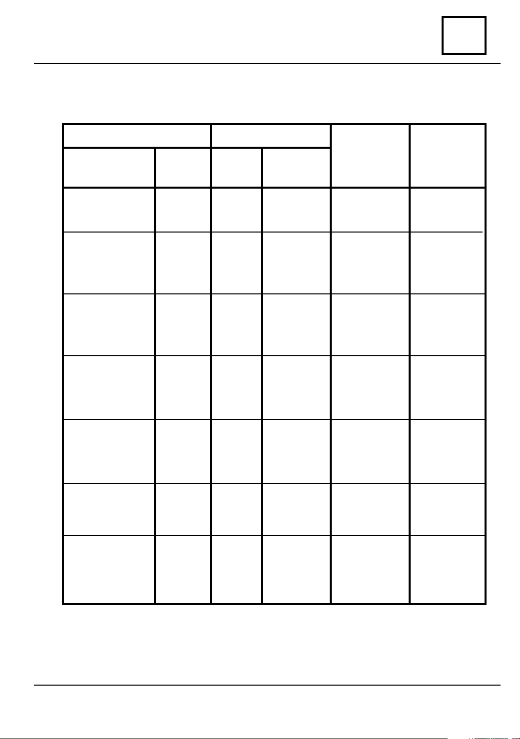
SPECIFICAT I ONS
vnx.su
ENGINE - CLUTCH - GEARBOX
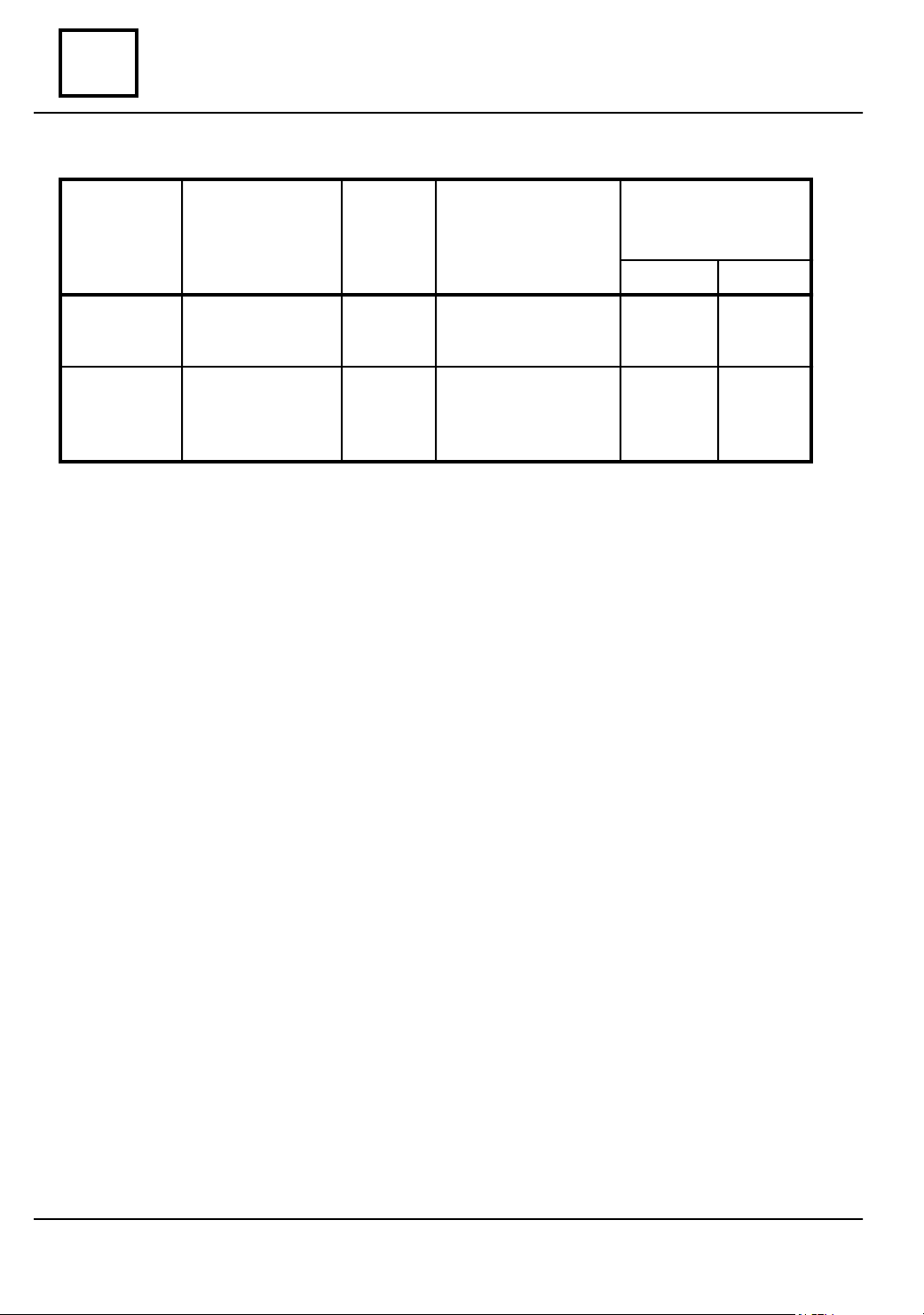
VEHICLE ENGINE
TYPE CODE
TYPE
CYLINDER
CAPACITY
(cmc)
01
CLUTCH GEARBOX
1304 Pick-Up
1304 Drop-Side
1304 King-Cab
1305 Pick-Up
1305 Drop-Side
D 26119
D 46169
D 27119
D 47169
D 2S119
D 4S169
D 16119
D 17119
106 -02
106 -10
106 -02
106 -10
106 -02
106 -10
106 -02
106 -10
102 -14
106 -02
106 -10
1557
1557
1557
1557
1557
1557
1557
1557
1397
1557
1557
200 GR
200 DBR
200 GR
200 DBR
200 GR
200 DBR
200 GR
200 DBR
200 GR
200 DBR
50 C
51 C
50 C
51 C
50 C
51 C
365
365
1305 King-Cab
1307
D 1S119
D 2F719
D 1F119
D 4F769
106 -02
106 -10
106 -02
106 -10
1557
1557
1557
1557
01 - 1
200 GR
200 DBR
200 GR
200 DBR
365
50 C
365
51 C
Page 5
SPECIFICAT I ONS
vnx.su
01
VEHICLE IDENTIFICATION
UNITL THE DATE OF 26.06.2003
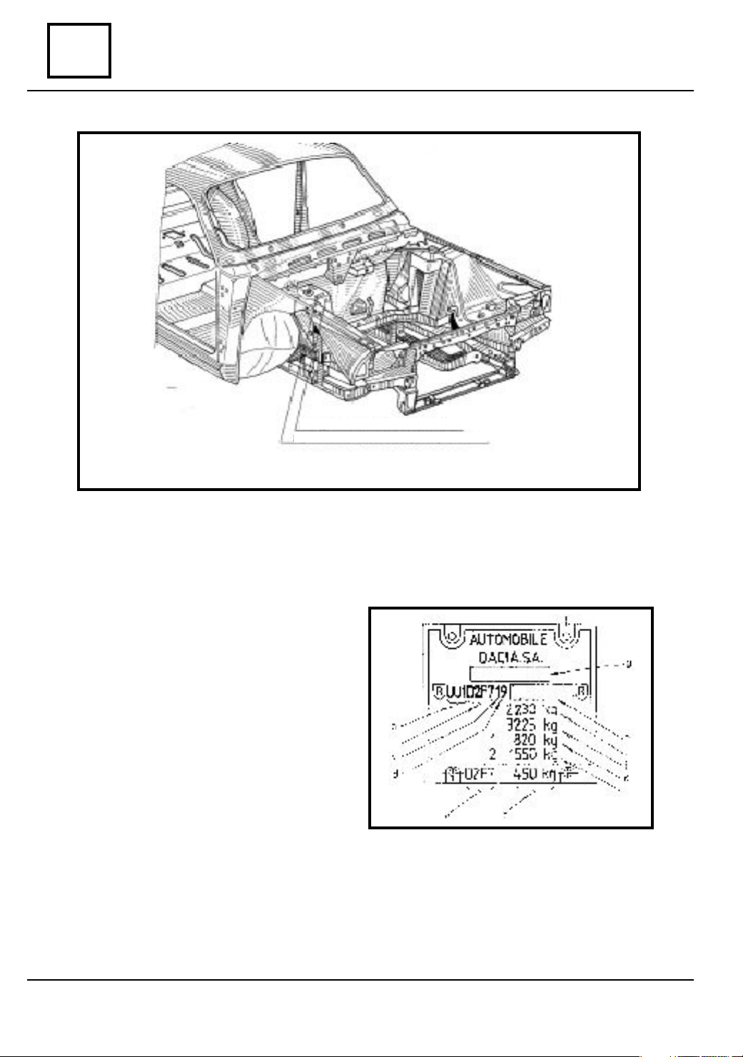
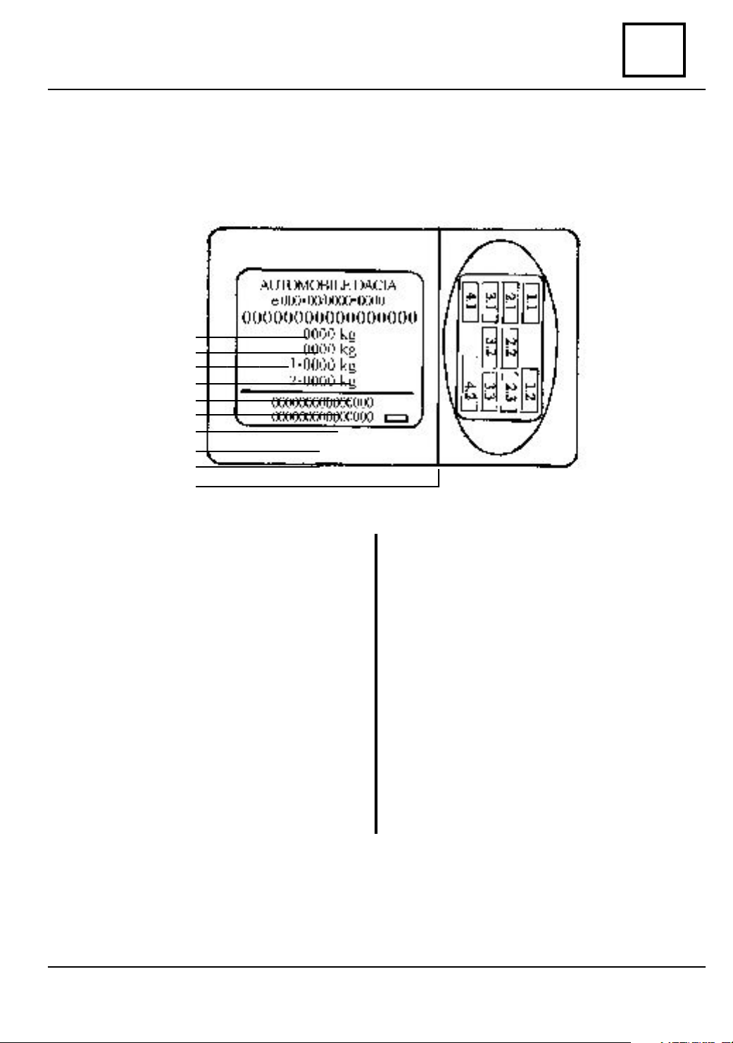
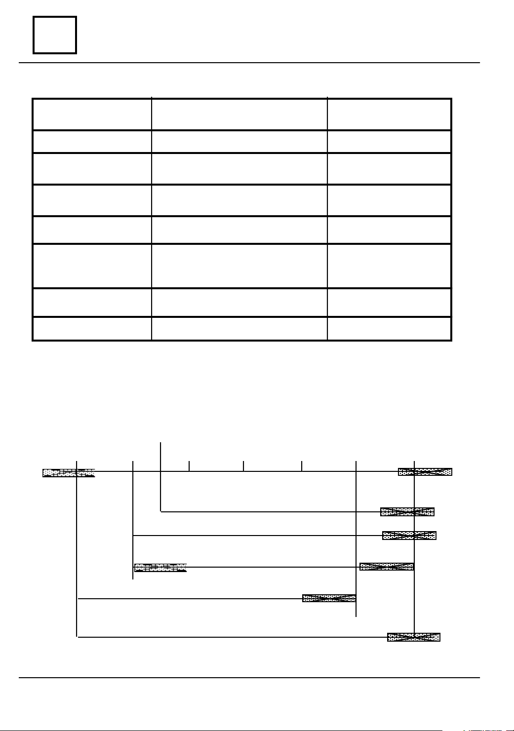
Manufacturer plate
Identification number VIN
MANUFACTURER PLATE
a. Manufacturer identification code;
b. Code of the vehicle;
c. Gear box type code;
d. Engine type code and driving device
location ( according to VIN code structure);
e.Vehicle code;
Maximum authorized weight without braking
f.
system;
g. Location place of the homologation number
for the importer country;
h. Location place of VIS sign ; one character
for the year model + 7 characters for the chassis
manufacture series ;
i. Maximum technical admissible weight of
the loaded car;
j. Maximum admissible weight with trailer
with braking system;
k.
Maximum technical admissible weight on
front axle
l.Maximum technical admissible weight on
rear axle.
;
01 - 2
Page 6
SPECIFICAT I ONS
vnx.su
VEHICLE IDENTIFICATION
UNITL THE DATE OF 26.06.2003
IDENTIFICATION NUMBER VIN
01
POSITION
COD U U 1 D
COD U U 1 D
COD U U 1 D
COD U U 1 D
COD U U 1 D
COD U U 1 D
COD U U 1 D
COD U U 1 D
COD U U 1 D
COD U U 1 D
COD U U 1 D
COD U U 1 D
POSITION CHARACTERS EXPLANATION
- chassis type
1 2 3 4 5 6 7 8 9 10 11 12 13 14 15 16 17
1 6 1 * * * * * * * * * *
1 7 1 * * * * * * * * * *
1
S 1 * * * * * * * * * *
2 6 1 * * * * * * * * * *
2 7 1 * * * * * * * * * *
2 S 1 * * * * * * * * * *
4 6 1 * * * * * * * * * *
4 7 1 * * * * * * * * * *
4 S 1 * * * * * * * * * *
1 F 7 * * * * * * * * * *
2 F 7 * * * * * * * * * *
4 F 7 * * * * * * * * * *
1 - 3 - manufacturer identification
UU1 - AUTOMOBILE DACIA S.A. ROMANIA
4 - vehicle type
D - merchandise transportation vehicle
5 - engine-gearbox unit location
1 - longitudinal front engine and front drive
2 - longitudinal front engine and rear drive
4 - longitudinal front engine and integral drive ( optional front coupling)
6 - type carosserie
6 - PICK-UP
7 - DROP - SIDE
S - KING CAB
F - PICK-UP, doble cabine
7 - payload location
1 - two front places + bed body
7 - 5 front places: 2 fixed rear bench for 3 places + bed body
8 - gearbox type
1 - gearbox with 5 + 1 steps
6 - gearbox with 5 + 1 steps and 4x4 coupling
9 - engine code and car driving location
9 - 1600 cmc engine, spark ignition, left hand drive
10 - year model code - Y - 2000; 1 - 2001; 2 - 2002
11 - 17 - chassis manufacturing series
01 - 3
Page 7
SPECIFICAT I ONS
vnx.su
01
VEHICLE IDENTIFICATION
UNITL THE DATE OF 26.06.2003
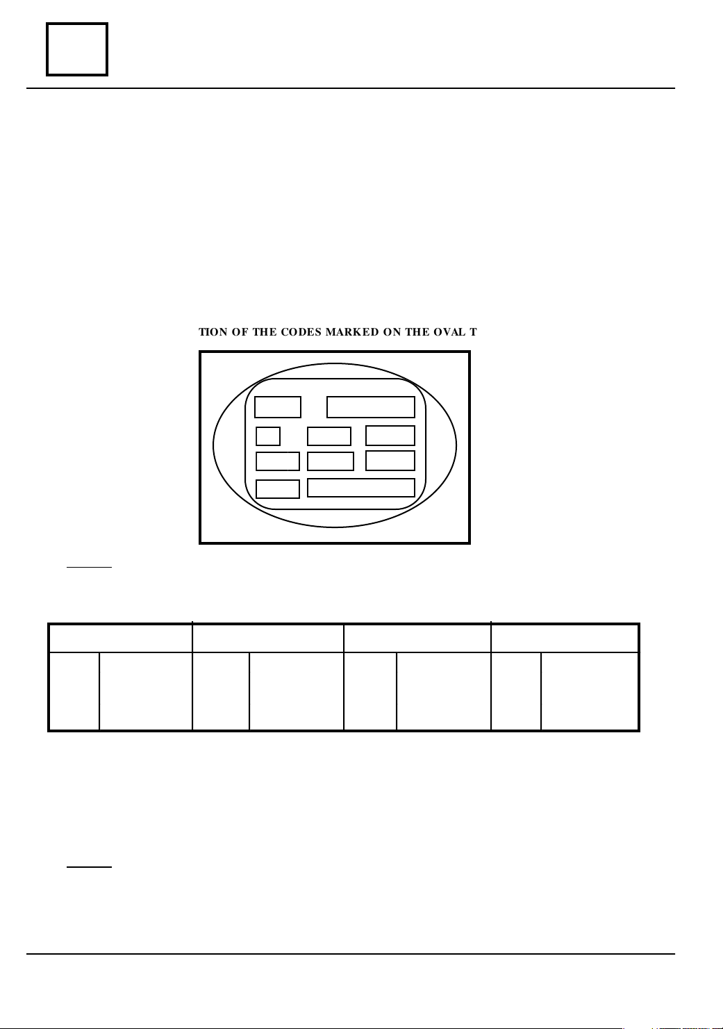
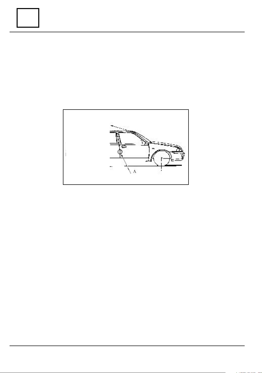
OVAL TYPE PLATE LABEL
The self-adhesive label is applied on the right part side surface of the dashboard. This
enable the identification of the vehicle type and its equipment, being used exclusively for
the after sale activity.
OVAL PLATE INSTRUCTIONS
HE INTERPRETATION OF THE CO DES MARK E D ON THE OVAL TYPE PLATE LABEL:
T
1,1
2,1
2,2
4,1
4,2
Line 1
1.1 Vehicle type code after sale:
Pick-Up Drop - Side King - Cab Double Cab
U 75 B
U 75 C
U 75 D
1305 Ri
1304 Ri
1304 4 WD Ri
E 75 B
E 75 C
E 75 D
1305 Ri
1304 Ri
1304 4 WD Ri
M 75 B
M 75 C
M 75 D
1305 Ri
1304 Ri
1304 4 WD Ri
Note: U,E, M, H = express the carriage body type
B,C,D = express the C type engine, 1557 cmc, front transmission type, rear and
consequently 4x4
75 = the code for R12 alternatives
Line 2
H 75 B
H 75 C
H 75 D
1307 FRi
1307 Ri
1307 4 WD Ri
2.1 Equipping level: E1,CA (air conditioning)
2.2 Country code: ROUM (Romania, with EU 96).
01 - 4
Page 8

SPECIFICAT I ONS
vnx.su
VEHICLE IDENTIFICATION
UNITL THE DATE OF 26.06.2003
OVAL TYPE PLATE LABEL
Line 4
4.1 Tehnical definition code, driving post:
S2: Left hand drive
4.2 Optional equipping code:
A: Normal suspension
C: Temperate climate
E: Warm climate
F: Normal heating
G: Air conditioning
K: Without pre-filter
M: Mechanical steering system
R: Without adjustable shock absorber
T: Without plate corrector
V: Without wheels ABS ( anti-blocking )
01
ATTENTION!
Do not unstuck or damage the label of the right side part surface of the
dashboard.This label represents the only way of vehicle identification, needed by the
after-sale services, for a period of 8 ( eight ) years from the purchasing date.
01 - 5
Page 9
SPECIFICAT I ONS
vnx.su
01
Vehicle identification
STARTING WITH THE D ATE OF 26.06.2003
MANUFACTURER’S PLATE DISPOSAL TYPE SELF-ADHESIVE
Fig.2.1
01 - 6
Page 10
SPECIFICAT I ONS
vnx.su
Vehicle identification
STARTING WITH THE D ATE OF 26.06.2003
The MANUFACTURER PLATE, self-adhesive type, has the bellow presented configura-
tion, with two distinctive areas, presenting :manufacturer’s identification data and APV type
identification data.
A
B
C
D
E
F
G
H
I
J
01
MANUFA CTURER’S IDENTIFICA-
TION DATA
A. Manufacturer’s name
B. Community reception number or
homologation number.
C. Identification number.
D. Total authorized weight of the
loaded vehicle.
E. Total authorized running weight
F. Total weight on front axle.
G. Total weight on rear axle.
H. Additional inscription.
I. Manufacturing date inscription
J. Consignment number.
APV ID ENTIFICATION DATA
1.1Code type auto APV
1.2Manufacturing number
2.1 Equipping level code
2.2 Additional code for limited serial
definition
2.3 Additional code for special serial
definition
3.1 Carriage body color code
3.2 Seats upholstery code
3.3 Interior matching code.
4.1 Technical definition code
4.2 Optional equipping code.
01 - 7
Page 11
LIFTING
vnx.su
MOBILE JACK AND PROTECTION ROUTE
It absolutely forbidden the vehicle lifting using the front or rear suspension arms as
supporting points.
The mobile jack shall not be used to lift the car in order to perform certain operations
under the carriage body.
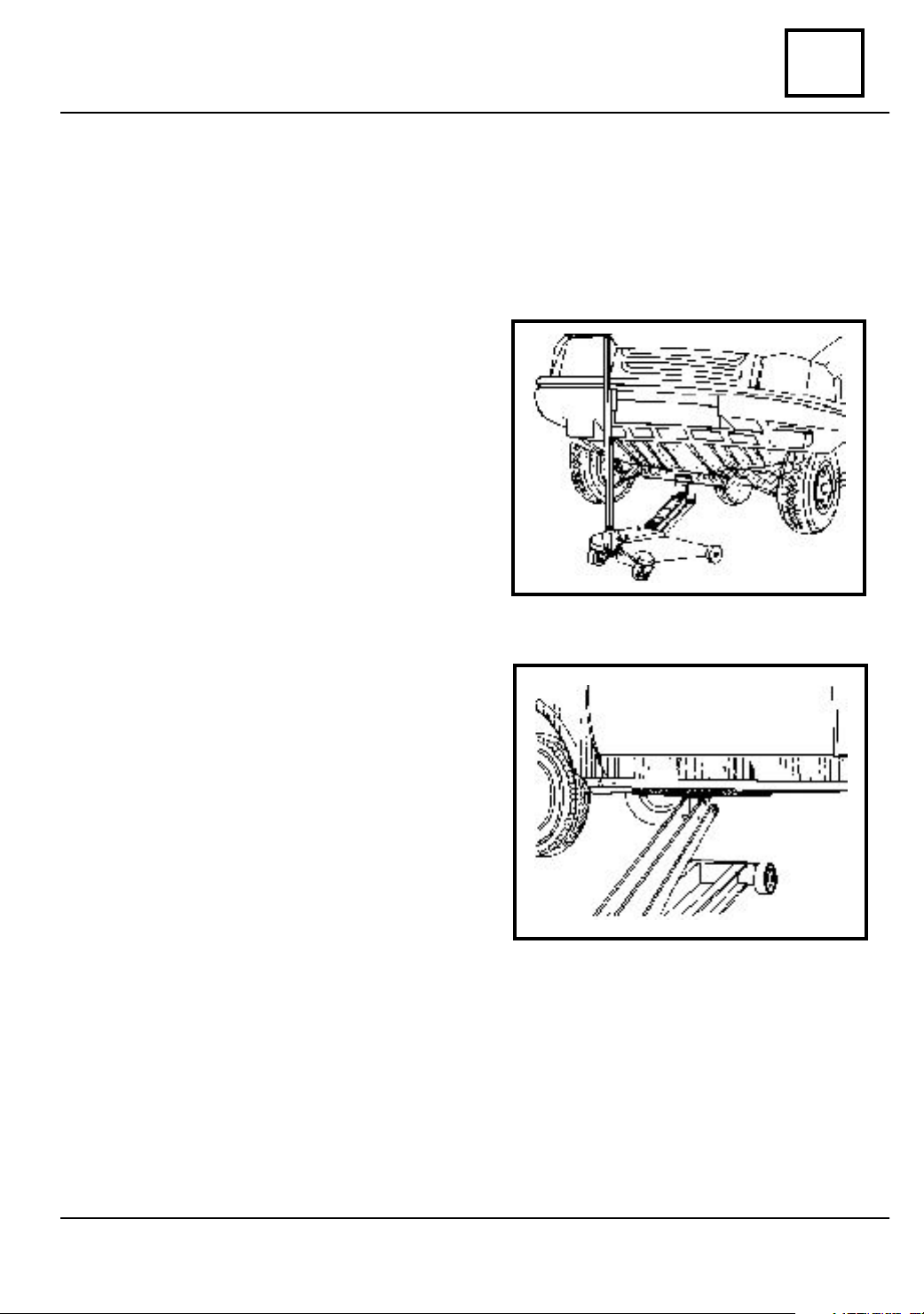
LIFTING THE FRONT PART OF THE
CAR
For lifting, the rolling jack and the
CHA 280 hold are used, in order to protect
the body and mechanical item of the car,
which are placed on longitudinal girders on
wheels axle.
02
LIFTING THE CAR FROM ONE SIDE
For lifting the car from one side, the
rolling jack and the CHA 280 hold shall be
used which are placed on the threshold on t he
front door.
The edge of the threshold shall be correctly
positioned in the channel of the hold.
02 - 1
Page 12
LIFTING
vnx.su
02
vehicle is usually placed.
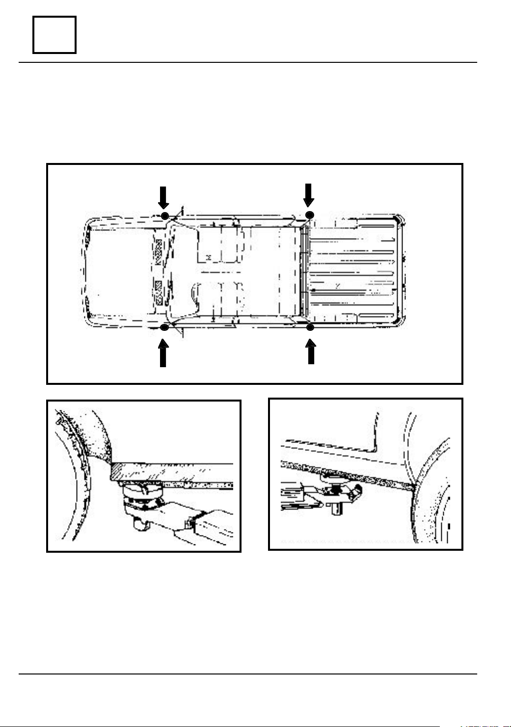
ELEVATOR POSITIONED UNDER THE CARRIAGE BODY
For lifting, place the elevator buffers on the same points where the car jack of the
The edge of the threshold shall be placed correctly in the buffer channel.
02 - 2
Page 13
TOWING
vnx.su
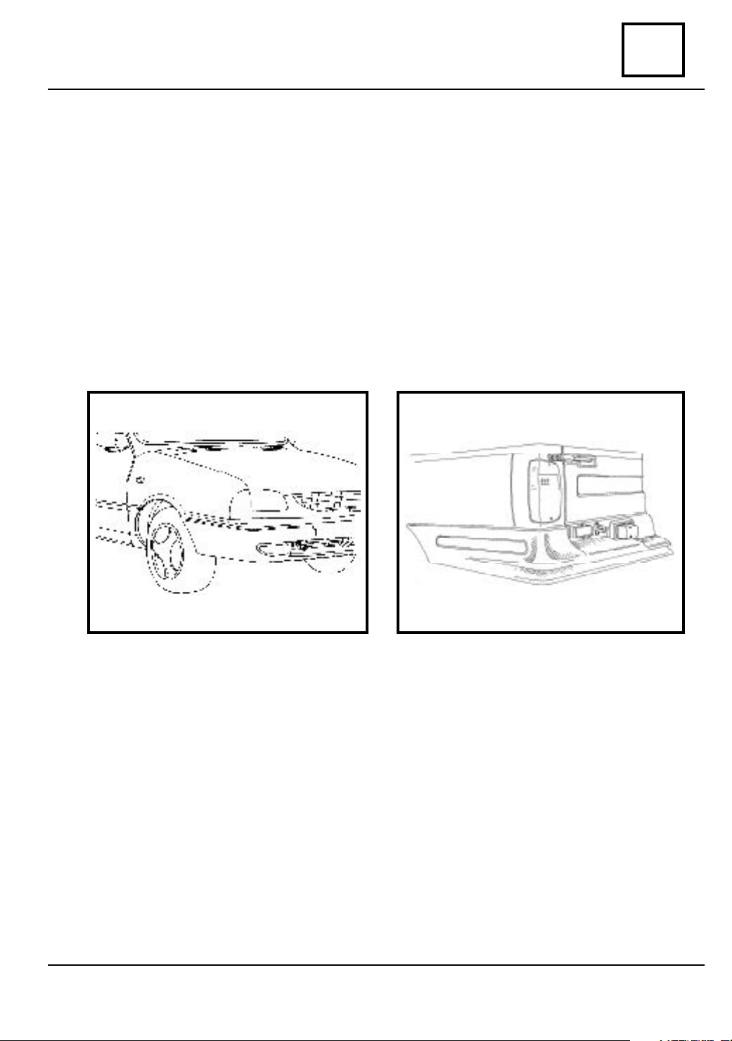
ALL TYPES
FOR TOWING OBSERVE THE LAW IN FORCE OF EACH COUNTRY
NEVER PERFORM TOWING USING FRONT TRANSMISSION
The towing of the cars on wheels must be obligatory done by means of the unique
towing points
These points cannot be anyhow used for drawing out the car from a trench ( hole ), for
a similar intervention or for direct or indirect lifting of the car.
RONT
F
REAR
03
03 - 1
Page 14
LUBRICANTS CONSUMABLES
vnx.su
CONDITIONS
04
PRODUCT
Grease
UM 170 Li Ca Pb 2M
ELF CARDREXA RNT2
UM 185 Li 2M
Grease
UM 185 Li 2M
Grease U 95 Ca 2
Grease
Li Ca Pb type II with MoS2
(or 20 UM Li III)
PLACE WHERE IT IS USED
GREASING
Clutch shaft groves
Pinions groves of front transmission
Gear box control lever
Pressure bearing
Cardan flange sealing ring
Front transmission
Front wheel steering stub groves
Cardanic transmission
Front transmission
Front wheel bearing
Suspension ball joints
Rear axle differential
Wheels screws
Steering gear (pinion – rack gear, bearings)
Grease 22
Grease U100 Ca 4-5
Rubber gaskets of the steering gear
Steering rod
04 - 1
Page 15
LUBRICANTS CONSUMABLES
vnx.su
04
PRODUCT
RHODORSEAL
5661
LOCTITE 518
LOCTITE 577
CONDITIONS
PLACE WHERE IT IS USED
SEALING
Inferior crankcase
Distribution cover
Propeller shaft pins
Half crankcase
Clutch crankcase
Fuel pump ( with membrane )
Cover palier 1
Rear axle
Thread of the reverse lamp contact.
Gear box plug M 16
Rear axle
Mastic 503
FIXAMED M28
DECAPJOINT
S.E. DERO 100
Differential rear axle
SOLDE RING
Screws of flywheel fixing
Screws of crank shaft pulley
CLEANING
The surface of cylinder head gasket
Wa shing of steel, cast iron, aluminum parts
04 - 2
Page 16
DRAINING AND FILLING
vnx.su
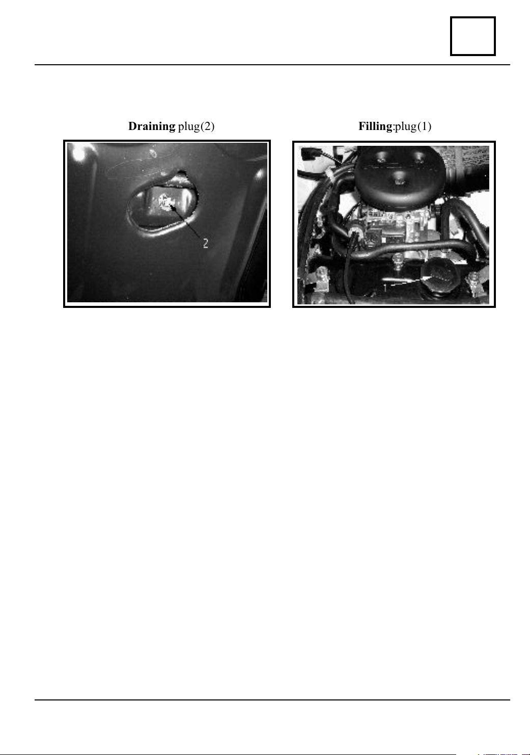
ENGINE
Necessary special tools - wrench for draining plug : CV 514
Draining: plug (2) Filling: plug (1)
05
05 - 1
Page 17
DRAINING AND FILLING
vnx.su
05
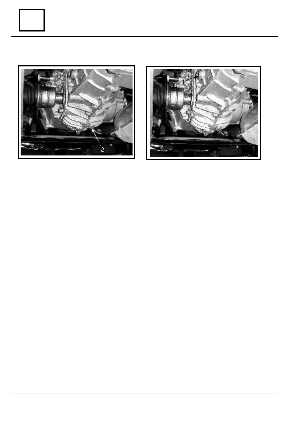
Draining: plug (2)
GEARBOX
Filling: plug (1)
05 - 2
Page 18
DRAINING AND FILLING
vnx.su
REAR AXLE DIFFERENTIAL
Draining: plug(2) Filling: plug (1)
05
05 - 3
Page 19
VALUES AND SETTINGS
vnx.su
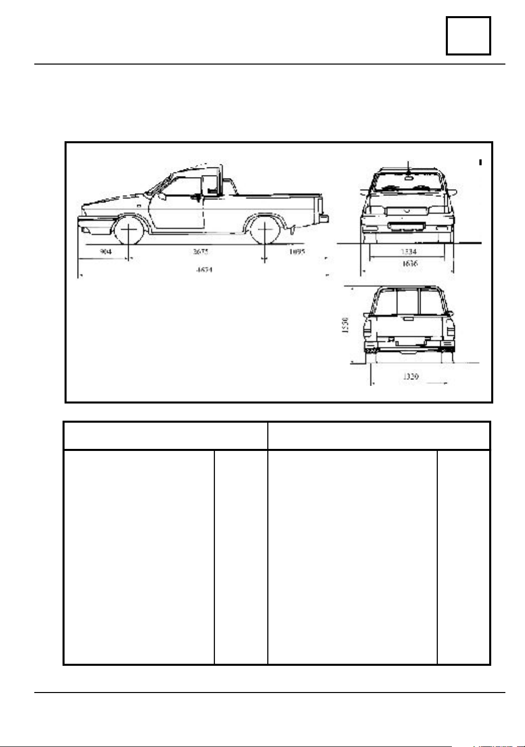
DIMENSIONS
DACIA 1304 PICK - UP
DACIA 1305 PICK - UP
07
DIME NSIONS ( mm ) WEIGHT ( kg )
Total length
Total width
Total height
Empty
Loaded
Axle base
Front wheel track width
Rear wheel track width
Ground clearance
Empty
Loaded
Turn radius
Between footways
Between walls
4674
1636
1550
1450
2675
1334
1320
-
165
5600
5800
Unloaded vehicle weight
On the front axle
On the rear axle
Total
Maximum authorized load
On the front axle
On the rear axle
Total
Authorized payload
Load with trailer with own brake
Load with trailer without own
brake
07 - 1
600
480
1080
760
1550
2250
1000
3225
2630
Page 20
VALUES AND SETTINGS
vnx.su
07
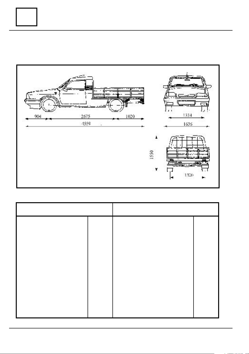
DIMENSIONS
DACIA 1304 PLATFORM
DACIA 1305 PLATFORM
DIME NSIONS( mm )
Total length
Total width
Total height
Empty
Loaded
Axle base
Front wheel track width
Rear wheel track width
Ground clearance
Empty
Loaded
Turn radius
Between footways
Between walls
4599
1615
1550
1450
2675
1334
1320
-
165
5600
5800
EIGHT ( kg )
W
Unloaded vehicle weight
On the front axle
On the rear axle
Total
Maximum authorized load
On the front axle
On the rear axle
Total
Authorized payload
Load with own brake trailer
Load without own brake trailer
07 - 2
595
520
1115
760
1550
2230
1000
3225
2630
Page 21
VALUES AND SETTINGS
vnx.su
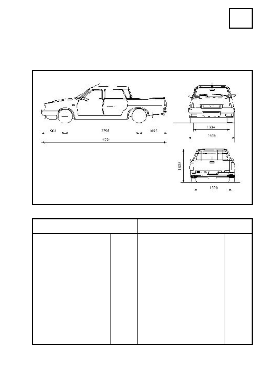
DIMENSIONS
DACIA 1307
07
DIME NSIONS ( mm )
Total length
Total width
Total height
Empty
Loaded
Axle base
Front wheel track width
Rear wheel track width
Ground clearance
Empty
Loaded
Turn radius
Between footways
Between walls
4794
2636
1525
2795
1310
1334
-
165
5600
5800
EIGHT ( kg )
W
Unloaded vehicle weight
On the front axle
On the rear axle
Total
Maximum authorized load
On the front axle
On the rear axle
Total
Authorized payload
We i ght on towing hook
07 - 3
635
540
1175
820
1550
2230
680
1055
max.50
Page 22
VALUES AND SETTINGS
vnx.su
07
DENOMINATIO CAPACITY (liters)
Engine oil
Gearbox oil
Differential oil
Breaking fluid
Cooling fluid *
Refrigerant A.C.
SAE 15 W 40 / API SJ/CF
CAPACITY - QUALITIES
CHARACTERISTICS
SAE 80 W 90 / API GL4/GL5
SAE 80 W 90 / API GL 5
SAE J 1703; DOT 4
Tip C
Tip D - GLACEOL RX **
(from 26.11.2001 )
HFC 134 a
PAG SP 10
3
2,3
2
0,3
6
0,700 kg,
Oil compresor
* Mixture: 50 % concentrate antifreeze + 50 % distilled water.
** On the expansion vessel a label is stacked specifying the use of this type
of cooling fluid.
Engine oil quality
-15°C
-30°C -20°C -10°C 0°C +10°C +20°C +30°C
15 W 40 - 15 W 50
10 W 40 - 10 W 50
10 W 30
5 W 30
265 cmc
5 W 40 - 5 W 50
07 - 4
Page 23
VALUES AND SETTINGS
vnx.su
DRIVING BELTS TIGHTENING AND TIGHTENING CHECKING
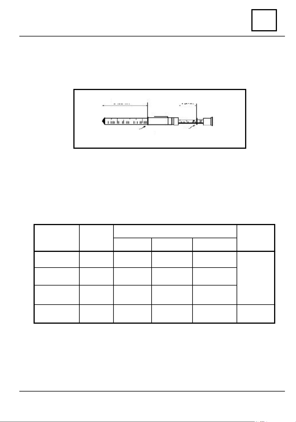
The checking of the belt tightening may be done by means of the MOT 557 device which
has two scales; one shows the arrow’s value ,and the other implicitly translates the value
of the tension ( force ).
07
Arrow
Ring 0 big Ring 0 small
Force
When checking and adjusting the belts tension, observe the following procedure:
∗ stretch the belt for which the tension is to be determined;
∗ place the big “O” ring on the scale at the arrow imposed value ( 2mm ; 4,5mm;
3,5 mm or 7,5 mm for the belts 1; 2 ; 3 or 4);
ORCE N (N)
BELT
between compressor
1
- alternator
ARROW f
(mm)
2
OUNTING AFTER 5 min.
M
14 +/- 15%
F
14 +/- 15%
A
FTER 500 km.
11 +/- 15%
VEHICLE
OPTIONALS
between crankshaft-
2
compressor
between crankshaft-
3
water pump
between crankshaft-
water pump -
4
alternator
4,5
3,5
7,5
17 +/- 15%
7.5 +/-15%
30 +/-15%
17 +/- 15%
7.5 +/- 15%
30 +/-15%
13 +/- 15%
5.5 +/- 15%
-
with AC
without AC
* place the small ”O” ring on the scale at zero value;
∗ place a metallic graduated rule on both pulleys;
* place the device at half- and vertical on the rule ( 1- distance between pulleys axles).
07 - 5
Page 24
VALUES AND SETTINGS
vnx.su
07
* press on the device until the big “O” ring passes over the rule;
∗ read the value of force N on the scale with small “O” ring;
∗ compare the read value with the imposed value :
adjustment of the distance between pulleys axles ( re tighten the belt ), until obtaining a
value within the imposed range.
∗ start the engine, run it for five minutes, check again the belt tension and compare it
with the imposed value and adjust it if necessary;
∗ check the tension and correct if necessary the belts tightening at 1000 km compulsory
checking.
DRIVING BELTS TIGHTENING AND TIGHTENING CHECKING
-if the N force value is within the imposed range, the belt tightening is good;
-if the read value is bigger or smaller than the imposed value, perform the
07 - 6
Page 25
VALUES AND SETTINGS
vnx.su
CYLIDER HEAD TIGHTENING A ND R ETI GHTENING
ATTENTION!
In order to obtain a correct tightening of the cylinder head screws, clean the attachment
holes of the cylinder head of oil or coolant liquid, by means a syringe.
Grease the thread of screws with engine oil.
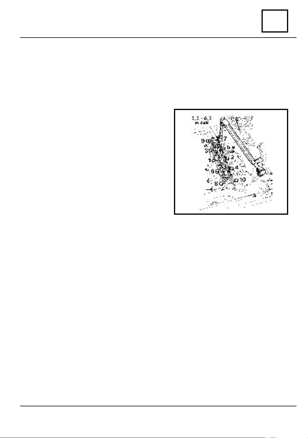
CYLINDER HEAD TIGHTENING
Tighten at the required moment (6,5 daNm)
observing the tightening sequence from the
drawing.
CYLINDER HEAD RE TIGHTENING
Retightening of the cylinder head is
performed as follows:
- for new vehicles at the 800 – 1000 km
check u;
- in case of engine repairing, which
implies the cylinder head dismounting, after
800 – 1000 km driving;
- every 10.000 km.
07
For retightening, loose the screw (1) with 1/4 rotation, after that retighten it to the
require moment:
- 6,5 daNm at warm (50 min. after engine shopping);
- 5,5-6,5 daNm at cold.
Repeat this operation also for the other screws, observing the sequence showed in the
drawing.
07 - 7
Page 26
VALUES AND SETTINGS
vnx.su
07
TYPE
VEHICLE
1304
1307
1307 - 4WD
1305
1304 - 4WD
* Tightening moment of the wheels nuts (screws) 9 daNm.
∗ Axial run out: max 1,2 mm.
∗ Radial run out: max 1,2 mm.
∗ Pressure in tires to be checked at cold. The increase of tire temperature during
running implies a growth of pressure with 0,2 – 0,3 bar.
In case of checking the tires pressure at warm, consider this growth of pressure.
∗ The tires are TUBELESS type ( without air tube ).
WHEELS TYRES
5 J 14 with deport
48 mm
5 J 14 with deport
48 mm
WHEELS AND TYRES
ROLLING
CIRCUMFERENCE
(mm)
175 R 14
PR 8
175 R 14
PR 8
1920 +/- 25
1920 +/- 25
P
RESSURE
(daN/cm )
FRONT REAR
1,9
2,0
2
4,2
4,5
07 - 8
Page 27
VALUES AND SETTINGS
vnx.su
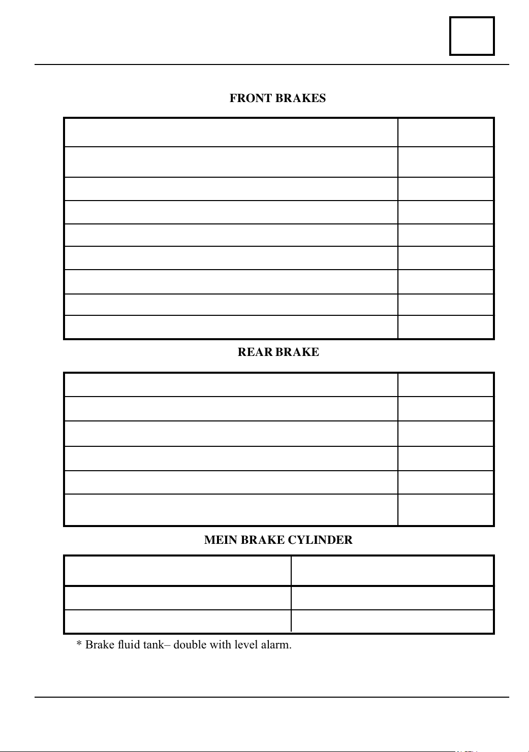
BRAKES
FRONT BRAKES
07
Brake caliper bore diameter (for brake disk non aerated)
Brake caliper bore diameter (for aerated brake disk)
Disk thickness non aerated
Disk thickness aerated
Minimal disk thickness non aerated
Minimal disk thickness aerated
Brake pad thickness ( the support included)
Minimal brake pad thickness (the support included)
Disk axial run out, measured at Φ215 mm
REAR BRAKE
Wheel braking cylinder diameter
New drum diameter
Φ 48 mm
Φ 54 mm
10 mm
20 mm
9 mm
19 mm
14 mm
7 mm
0,1 mm
Φ 25,4 mm
Φ 254 mm
Maximum drum diameter after grinding
Braking lining width
Braking lining thickness
Minimal accepted braking lining height above rivets
MEIN BRAKE CYLINDER
Type of main brake cylinder
Inner diameter
Max. pump stroke
* Brake fluid tank– double with level alarm.
∗ Pressure reducing valve for parallel circuit.
* Brake fluid as per norms SAE J 1703, DOT4.
07 - 9
Tandem master cylinder with ICP by
pass included
Φ 255 mm
50 mm
5 mm
0,5 mm
Φ 20,6 mm
32 mm
Page 28
VALUES AND SETTINGS
vnx.su
07
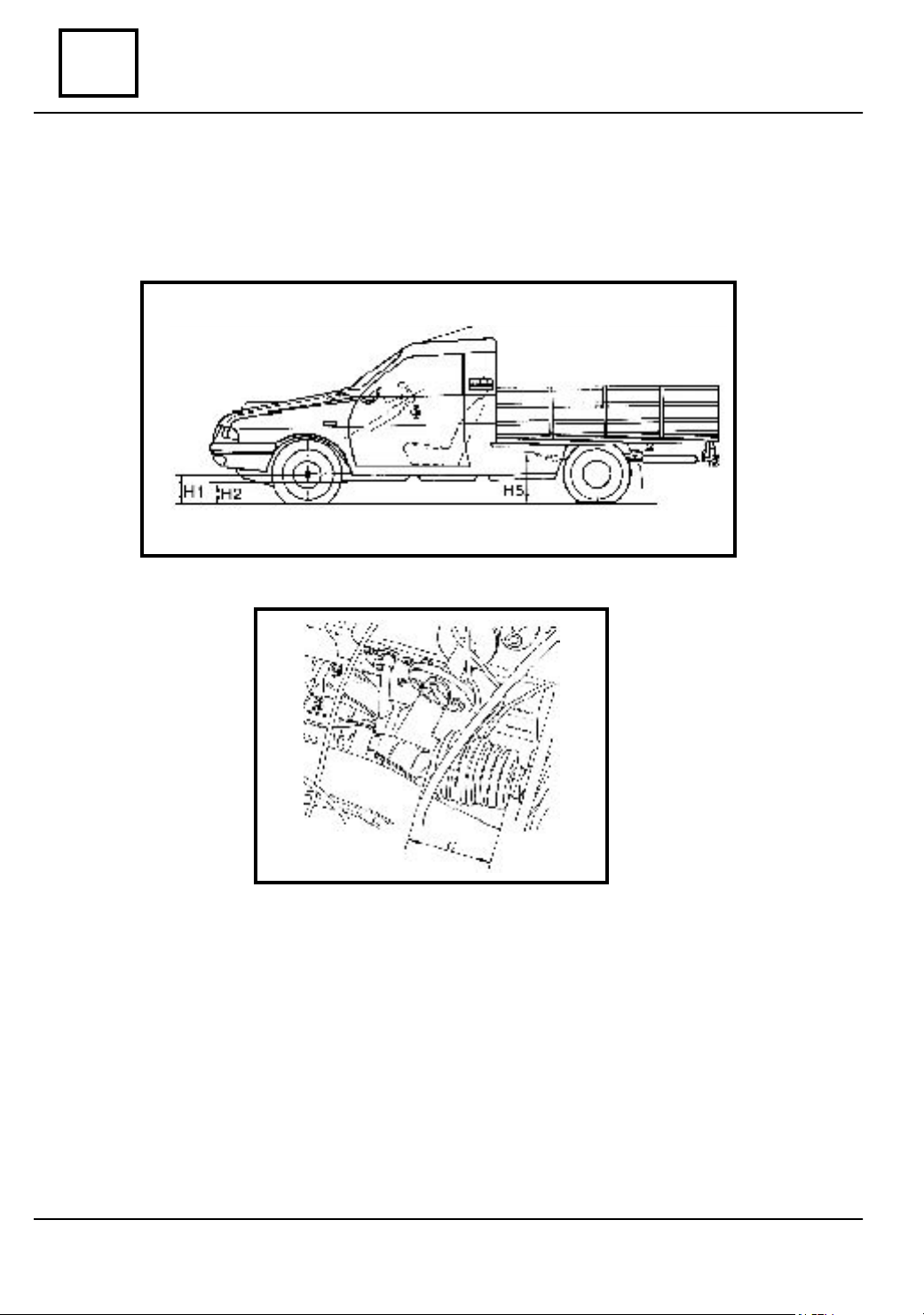
VA LUES UNDER CARRIAGE BODY CONDITIONING THE ADJUSTMENT OP-
HEIGHTS UNDER CARRIAGE BODY
ERATIONS OF THE STEERING ANGLES.
H1 – the distance measured from the wheels center to the ground
H2 – the distance measured from the longitudinal girder lower part to the ground
H5 – the distance measured from the joint axis of the front leaf spring to the ground,
measured in the area of the lower arm attachment.
C – this value is showing the position where the rack must reach in order to obtain the
middle point for the steering rack.
07 - 10
Page 29
VALUES AND SETTINGS
vnx.su
CONTROL VALUE OF FRONT AXLE ANGLES
COMMERCIAL U 75 DRIVE (1304, 1307)
07
ANGLES
CASTER
CAMBER
BALL JOINT
TOTAL PARALLELISM
VALUES
0
11'
1
0
28'
1
0
45' ± 30'
1
0
02'
2
0
19'
2
0
0
36'
52'
2
2
Maximum Left / Right
difference = 1
0
10 22'
0
1
21'
0
20'
1
0
18' ± 30'
1
0
17'
1
0
15'
1
0
14'
1
Maximum Left / Right
difference = 1
0
01'
8
0
02'
8
0
03'
8
0
04' ±30'
8
0
05'
8
0
07'
8
0
08'
8
0
Maximum Left / Right
difference = 1
0
POSITION OF THE VEHICLE
1304 1307
H5 - H2 = 260
H5 - H2 = 250
H5 - H2 = 240
H5 - H2 = 230
H5 - H2 = 220
H5 - H2 = 210
H5 - H2 = 200
H1 - H2 = 66
H1 - H2 = 62
H1 - H2 = 58
H1 - H2 = 54
H1 - H2 = 51
H1 - H2 = 47
H1 - H2 = 43
H1 - H2 = 66
H1 - H2 = 62
H1 - H2 = 58
H1 - H2 = 54
H1 - H2 = 51
H1 - H2 = 47
H1 - H2 = 43
H5 - H2 = 265
H5 - H2 = 255
H5 - H2 = 245
H5 - H2 = 235
H5 - H2 = 225
H5 - H2 = 215
H5 - H2 = 205
H1 - H2 = 66
H1 - H2 = 62
H1 - H2 = 58
H1 - H2 = 54
H1 - H2 = 51
H1 - H2 = 47
H1 - H2 = 43
H1 - H2 = 66
H1 - H2 = 62
H1 - H2 = 58
H1 - H2 = 54
H1 - H2 = 51
H1 - H2 = 47
H1 - H2 = 43
ADJUSTMENTS
Adjustable by
modification of
the tie-rod
length from
previous
mounting
Not adjustable
Not adjustable
ELASTIC JOINTS BLOCKING
Opening (toe-in)
0
10’ ± 10’
0
(for one wheel
0
0
05’ ± 05”)
-
Empty
Empty
07 - 11
Empty
Adjustable by
means of the
tie rods rotation
Empty
-
Page 30
VALUES AND SETTINGS
vnx.su
07
ANGLES
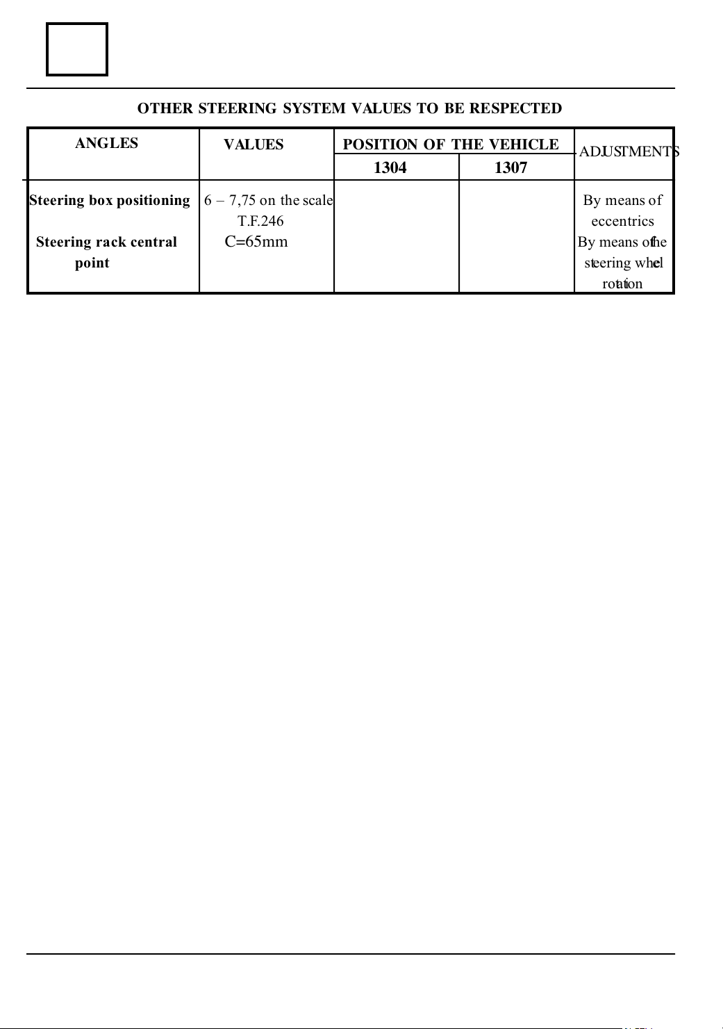
Steering box positioning 6 – 7,75 on the scale By means of
Steering rack central C=65mm By means of th e
point steering wheel
CONTROL VALUE OF FRONT AXLE ANGLES
OTHER STEERING SYSTEM VALUES TO BE RESPECTED
VALUES
T.F. 24 6 eccentrics
POSITION OF THE VEHICLE
1304 1307
ADJUSTMENTS
rotation
07 - 12
Page 31

VALUES AND SETTINGS
vnx.su
CONTROL VALUE OF FRONT AXLE ANGLES
COMMERCIAL U 75 / 4X4 DRIVE (1304, 1307)
07
ANGLES
CASTER
CAMBER
PIVOT
BALL JOINT
TOTAL PARALLELISM
VALUES
0
11'
1
0
1
29'
0
46' ± 30'
1
0
02'
2
0
19'
2
0
2
2
0
36'
53'
Maximum Left / Right
difference = 1
0
21'
1
0
20'
1
0
19'
1
0
18' ± 30'
1
0
16'
1
0
15'
1
0
13'
1
Maximum Left / Right
difference = 1
0
01'
8
0
02'
8
0
03'
8
0
04' ±30'
8
0
05'
8
0
07'
8
0
08'
8
0
0
Maximum Left / Right
difference = 1
0
Opening (toe-in)
0 160
-0
(for one wheel
0
08’± 05’)
-0
± 10
0
POSITION OF THE VEHICLE
1304
H5 - H2 = 260
H5 - H2 = 250
H5 - H2 = 240
H5 - H2 = 230
H5 - H2 = 220
H5 - H2 = 210
H5 - H2 = 200
H1 - H2 = 66
H1 - H2 = 62
H1 - H2 = 58
H1 - H2 = 54
H1 - H2 = 51
H1 - H2 = 47
H1 - H2 = 43
H1 - H2 = 66
H1 - H2 = 62
H1 - H2 = 58
H1 - H2 = 54
H1 - H2 = 51
H1 - H2 = 47
H1 - H2 = 43
Empty
1307
H5 - H2 = 265
H5 - H2 = 255
H5 - H2 = 245
H5 - H2 = 235
H5 - H2 = 22
H5 - H2 = 215
H5 - H2 = 205
H1 - H2 = 66
H1 - H2 = 62
H1 - H2 = 58
H1 - H2 = 54
H1 - H2 = 51
H1 - H2 = 47
H1 - H2 = 43
H1 - H2 = 66
H1 - H2 = 62
H1 - H2 = 58
H1 - H2 = 54
H1 - H2 = 51
H1 - H2 = 47
H1 - H2 = 43
Empty
ADJUSTMENTS
Adjustable by modifi-
cation of the tie-rod
length from previous
mounting
Not adjustable
Not adjustable
Adjustable by
means of the tie
rods rotation
ELASTIC JOINTS BLOCKING
-
Empty
Empty
-
07 - 13
Page 32

VALUES AND SETTINGS
vnx.su
07
ANGLES
Steering box positioning 6 – 7,75 on the scale By means of
Steering rack central C=65mm By means of th e
point steering wheel
CONTROL VALUE OF FRONT AXLE ANGLES
OTHER STEERING SYSTEM VALUES TO BE RESPECTED
VALUES
T.F. 24 6 eccentrics
POSITION OF THE VEHICLE
1304
1307
ADJUSTMENTS
rotation
07 - 14
Page 33

VALUES AND SETTINGS
vnx.su
CONTROL VALUE OF REAR AXLE ANGLES
COMMERCIAL U 75 DRIVE (1304, 1307)
07
ANG L E S
CAMBER
PARALLELISM
ELASTIC JOINTS BLOCKING
VALUES
00± 34'30''
(For two wheels)
To e out
00 ± 34'30''
VEHICLE
POSITION
Empty
Empty
Empty
Empty
ADJUSTMENTS
Not adjustable
Not adjustable
--
07 - 15
Page 34

VALUES AND SETTINGS
vnx.su
07
CONTROL VALUE OF REAR AXLE ANGLES
COMMERCIAL U 75 / 4 X 4 DRIVE (1304, 1307)
ANGLES
CAMBER
PARALLELISM
VALUES
0
0
± 19'59''
(For two wheels)
Toe out
0
± 19'59''
0
VEHICLE
POSITION
Empty
Empty
ADJUSTMENTS
Not adjustable
Not adjustable
ELASTIC JOINTS BLOCKING
Empty
* In order to check and adjust the front axle angles values, respectively the rear axle ones, the
following must be done:
- perform the tires checking concerning:
- dimensions
- inflating pressure
- degree of wear
- perform the joints checking:
- elastic joints condition
- ball joint clearance
- wheel bearing clearance
The vehicle must be obligatory:
- positioned with the wheels on bench rotating plates being in horizontal direction
- braked ensured
- suspension tested, for vehicle setting at its free height
- steering brought at central point and steering rack blocked in this position.
These operations are to be followed by optical device attachment on vehicle, observing the
prescriptions of the steering measurement bench manufacturer.
07 - 16
Page 35

ENGINE AND LOWER ENGINE UNITS
vnx.su
INGREDIENTS
YPE UTILISATION
T
RHODORSEAL 5661 Propeller shaft pins.
Oil sump and distribution cap.
LOCTITE 518 Petrol pump sealaing ( membrane type )
and cap of bearing no. 1.
OMNI - FIT RAPID ( FIXAMED M 28 ) Flywheel attachement screws,bearings
cap screws.
OIL SUPER 15 W 40 API SJ Engine lubrication,parts lubrication
when mounting.
S.E. DERO 100 Washing of steel,aluminium and cast
iron parts.
10
10 - 1
Page 36

ENGINE AND LOWER ENGINE UNITS
vnx.su
10
IDENTIFICATION
VEHICLE TYPE ENGINE GEAR BOX DISPLACEMENT BORE STROKE COMPRESS
3
)( mm ) ( mm )
( cm
1304 Pick-up 365
1304 Drop-side 106 - 10 50 C 1557 77 83,6 8,5:1
1304 King-cab 51 C
1305 Pick-up 365
1305 Drop-side 106 - 02 50 C 1557 77 83,6 8,5:1
1305 King-cab 51 C
1307 365 1397 76 77 8,5:1
102 - 14 50 C
ION RATIO
10 - 2
Page 37

ENGINE AND LOWER ENGINE UNITS
vnx.su
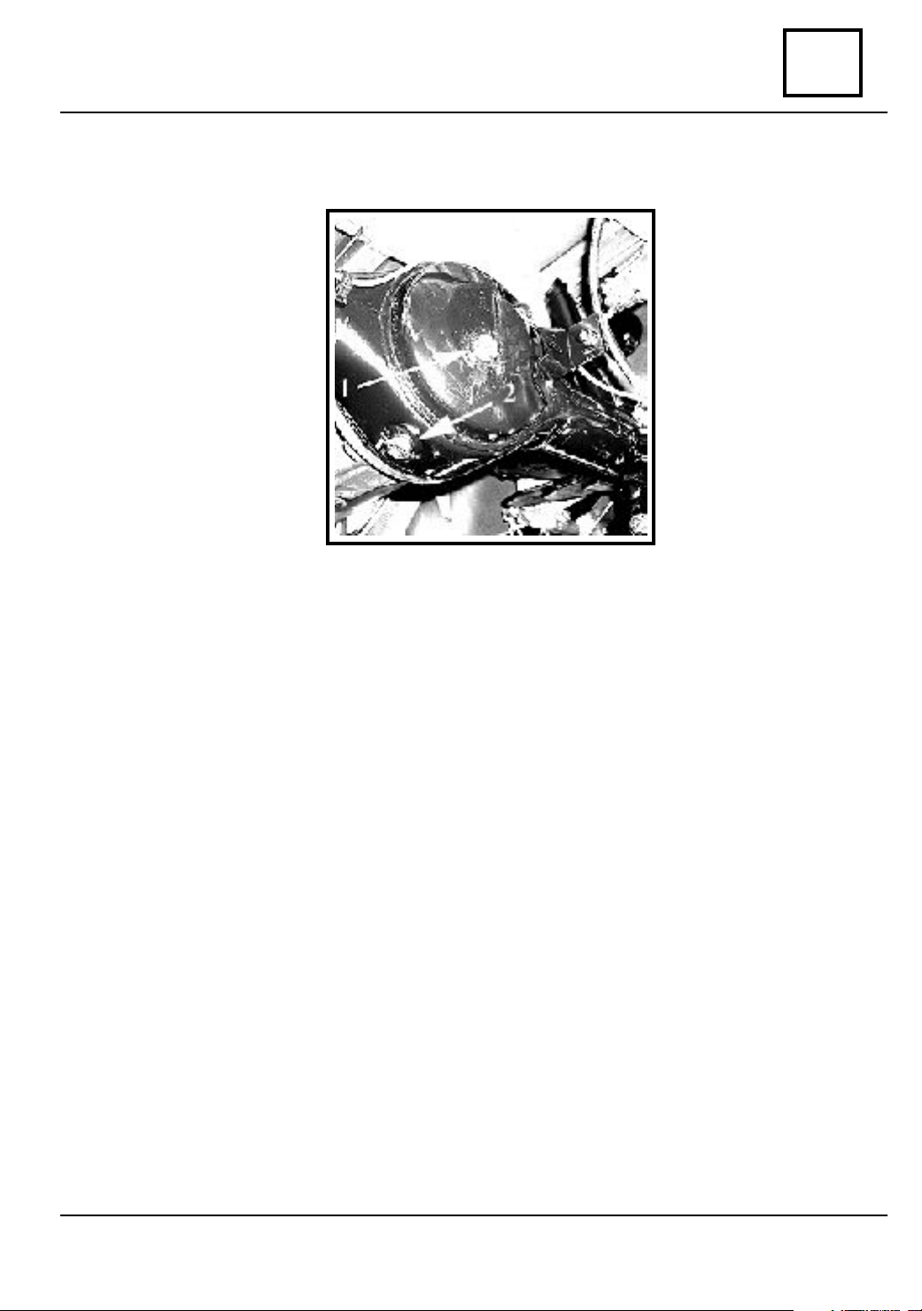
IDENTIFICATION
The engine identification is done by means of a plate attached to the cylinder block, above
the oil filter.
1. Type of engine.
2. Engine manufacture series.
10
10 - 3
Page 38

ENGINE AND LOWER ENGINE UNITS
vnx.su
10
Place the car on the elevator,dismount the engine shield,check the presence of oil leaks.
If there are any leaks,eliminate it and then check again.
Drain the oil from the engine.
Fill the engine w ith 2,750 l new oil 15 W 40, start the engine and let it run in force
( 1000 - 1200 rpm. ) during aprox. 10 minutes, then s top the engine.
Drain the oil previously filled,as per following procedures:
- emptying plug removed;
- piston of cylinder 1 at the upper dead point;
- draining time 20 min;
- the oil is collected in a special vessel which can be used both for filling and draining of the
oil.
Mount the emptying plug.
Weigh the vessel with the ollected oil by means of a s cale.Mark this value G1.
The oil is filled back in the engine,directelly from the special vesel.
Check the sealing of the emptying plug.
Keep the vessel with the oil traces remained after oil filling.
MEASUREMENT OF OIL CONSUMPTION
PREPARATION FOR TEST
CONSUMPTION TEST
ROAD TEST
Driving conditions to be constant as far as speed and charge are concerned, equivalent with
a 80 km/h speed on a horizontal road.
Do not force the acceleration.
Length of the route: 100 +/- 5 km.
OIL COLLECTING
Place the car on the elevator.
Drain the oil respecting the previous conditions.
The oil is collected in the same special vessel used for oil filling.
Weigh the vessel with the collected oil on the same scale and mark this value with G2.
10 - 4
Page 39

ENGINE AND LOWER ENGINE UNITS
vnx.su
MEASUREMENT OF OIL CONSUMPTION
CONSUMPTION CALCULATION
The oil consumption is given by the difference between the first weighing and the second
weighing.
Oil c onsumption G1 - G2.
ADMISSIBLE CONSUMPTION
The admissible consumption is determinated by:
- the wear general condition of the engine;
- the oil quality;
- driving style, rpm;
- engine tuning: carburattion.
The engines with a oil consumption greater of 100 grams at 100 km need to be adjusted.
For the cars within the warranty period,the maximum admissible oil consumption is 75 grams
at 100 km.
10
10 - 5
Page 40

ENGINE AND LOWER ENGINE UNITS
vnx.su
10
The oil pressure checking is done in the following conditions:oil to be up to the required level
and of a adequate quality; oil temperature to be 80 ºC.
To check the oil pressure use the following procedure :
- check the oil level and fill in until the required level is reached (if this is necessary); if the
oil is unsuitable (used) it shal be replaced.
- start the e ngine and let it run until the oil temperature reach 80 ºC.
- stop the engine and dismount the oil pressure transmitter;
- mount the MOT 73-01 manometer;
- connect a rotation meter;
- start the engine and check the pressure.
The recommended pressure is:
- 750-800 rpm - 0,7 bars
- 4000 rpm - 3,5 - 4 bars
- stop the engine,dismount the MOT 73-01 manometer and mount the oil pressure
transmitter;
- disonnect the rotation meter;
- chek the oil level and fill in up to the required level.
OIL PRESSURE CHECKING
10 - 6
Page 41

ENGINE AND LOWER ENGINE UNITS
vnx.su
OIL FILTER REPLACEMENT
DISMO UNT NG
Disconnect the battery.
Loosen the filter by means of the MOT 445.
Hand dismount the filter.
10
EMOUNTING
R
Lubricate the gasket of the new filter with oil.
Tighten the filter by hand untill the asket comes in the contact with the block.
Tighten 1/2 rotation more by means of the MOT 445 wrench.
Loosen the filter,bring the gasket into contact with the block and tighten 1/2 -3/4 more rotations.
Check and fill with oil up to the required level in the engine.
10 - 7
Page 42

ENGINE AND LOWER ENGINE UNITS
vnx.su
10
ENGINE DISMOUNTING - REMOUNTING
The engine may be independently dismounted by taking it out through the upper part
of theengine compartment.
ISMOUNT ING ( in the engine compartment )
D
Disconnect the battery.
Dismount the engine hood.
Dismount the plug of the cylinder head
cap,the plug of the oil casing and drain the oil
from the engine.
Drain the cooling circuit:
- dismount the radiator plug;
- dismount the cylinders block plug.
Dismount the watter and fuel ducts.
Dismount the radiator.
Dismount the fan,the belt and the fan pulley
of the watter pump.
Disconect the electric wires
(alternator,thermocouplings,oil pressure
transmitter,coil;breaker);
Dismount the cables:
- acceleration and shock;
Dismount the throttle valve spring.
Dismount the air filter.
Dismount the starter protection.
gearbox on the engine.
Dismount the starter cables.
Dismount the starter.
Unscrew the fixing screws of the
10 - 8
Page 43

ENGINE AND LOWER ENGINE UNITS
vnx.su
ENGINE DISMOUNTING - REMOUNTING
DISMO UNT ING (under the car )
Dismount the engine shield.
Dismount the beam between the
longitudinal girders.
Dismount the nuts that attach(fix) the bushings
the stabilizer rod.
Dismount the nuts that attach the gearbox to
the engine.
Dismount the protection plate of the clutch.
Dismount the pulley of the crakshaft.
Dismount the attachment ring of the
discharge tube.
Unscrew the nuts that attach the engine
supports to the buffers.
Deposer les ecrous de fixation des supports
moteur au tampon.
10
to
Place a jack under the gearbox.in order to
maintain it in the right position.
Mount the lifting device.
Displace the engine forward and lift it.
Place the engine on the support.
EMOUNTING
R
The dismounting operations are to be performed in reverse order.
10 - 9
Page 44

ENGINE AND LOWER ENGINE UNITS
vnx.su
10
Check the existance of the two bushings by means of which the clutch casing is centered on
the block.
Slightly grease ( thin coat) the clutch shaft grooves with Li Ca Pb type II grease.
Adjust the stroke of the acceleration pedal.
Perform:
- the filling with oil of the engine;
- the filling and aeration of the cooling circuit.
Adjust the engine running (ignition ,carburation).
Tighten the fixing nuts and screws according to the tightening moments given in the bellow
table:
ENGINE DISMOUNTING - REMOUNTING
PA RTICULARS ON REMOUNTING
NGINE MOUNTING - DISMOUNTING
E
FIXING TIGHTENING MOMENTS
(daN.m)
Caps to bearings 5,50 - 6,50
Caps to connecting rods
Flywheel 5
Cylinder head to casing ( at cold)
Cylinder head cap
Tilter shaft support
Camshaft pinion
Camshaft clip
Oil pump on casing
Lower casing
Clutch mechanism
Clutch mechanism φ 200 DBR/ φ 200 GR 1,50 - 2,00
Distribution cap
Oil emptying plug
Pump and water pump cap
Fan 2,00 - 2,50
Starter screen 2 - 3
Fuel pump 1,50 - 2,00
Thermocontact1,50 - 2,00
Oil pressure trasmitter 2
Carburettor 1,50 - 2,00
Crankshaft pulley 6,50
Alternator support 1,00 - 1,75
φ 180 DBR 1,00 - 1,20
0,70 - 1,00
4,00 - 4,50
5,50 - 6,50
0,15 - 0,45
1,50 - 1,75
2,70 - 3,20
0,80 - 1,00
0,70 - 1,00
1,20 +/- 0,40
max. 3,5
0,70
10 - 10
Page 45

ENGINE AND LOWER ENGINE UNITS
vnx.su
10
ENGINE AND GEARBOX DISMOUNTING - REMOUNTING
The engine-gearbox assembly may be dismounted from the car only by taking it out at the
uper part of the engine compartment.
ISMOUNT ING ( inside the engine compartment )
D
Perform the operations described for the sole engine dismounting,except the following
operations:
- dismounting of the starter protection;
- dismounting of starter;
- dismounting of the screws fixing the gearbox to the engine.
Perform additionally:
- dismounting of the clutch cable.
ISMO UNTING ( under the car )
D
- dismounting of clutch protection plate;
- dismounting the nuts of fixing the gearbox
to the engine.
Perform additionally:
- gearbox oil draining;
- disconnecting the wires of the baking
connector.
Dismount the speedometer cable;
Dismount the fixing bolt of the speeds
connecting rod.
Dismount the fixing nut of the exhaust pipe on
the cross bar of the gearbox.
Dismount the elastic pins of the transmission.
10 - 11
Page 46

ENGINE AND LOWER ENGINE UNITS
vnx.su
10
ENGINE AND GEARBOX DISMOUNTING - REMOUNTING
Place the cross bars supporting the front axle.
Dismount the front wheels.
Dismount the upper suspenssion ball joints and
the ball joints of the steering connecting rod.
Disconnect the transmissions.
.
Place a jack under the gearbox to maintain it
in the right position.
Dismount the back cross bar of the gearbox.
Dismount the fixing nuts of the engine supports.
10 - 12
Page 47

ENGINE AND LOWER ENGINE UNITS
vnx.su
ENGINE AND GEARBOX DISMOUNTING - REMOUNTING
10
Remove the jack from under the gearbox.
Mount the lifting device.
Move the engine-gearbox assembly
forward,bend it and lift it.
Place the engine on support.
Dismount the gearbox ( if necessary).
EMOUNTING
R
Perform in the reverse order the operations descibed at the dismounting.
PA RTICULARS UPON REMOUNTING
Slightly grease with grease Li Ca Pb type II the grooves of the front axles pinions.
Upon mounting the elastic pins,the notches shall be oriented towards the exterior (wheel).After
mounting ,a ball of sealer shall be placed at the ends of the pins,for sealing.
Adjust the cl utch stroke: 2,5 – 3 mm.
Perform :
- oil fill up of the gearbox and the engine;
- filling and aeration of the cooling system.
Adjust the engine running (ignition and carburation).
Adjust the speeds command (see chapter 37 “ Speeds command ”).
Tighten the fixing nuts and screws according to the moments mentioned in the bellow table:
FIXING TIG H TENING
MOMENTS ( daNm )
Gearbox control connecting rod 4
Steering connecting rod 3
Upper shaft ball joint 5
Gearbox filling and draining plug 2,50
Downlead tube clip for exhaust pipe 1,70
Engine support on block 1,70
Buffer on support 1,70
Gearbox cross bar on gearbox 1,20
Cross bar on lateral buffers 1,70
10 - 13
Page 48

10
vnx.su
ENGINE AND LOWER ENGINE UNITS
TIGHTENING BY S CREWING UP MOMENTS
10 - 14
Page 49

ENGINE AND LOWER ENGINE UNITS
vnx.su
CHARACTERISTICS
ENGINE TYPE 102 - 14 106 - 02 106 - 10
Cylinder (cmc)
Bore (mm)
Stroke (mm)
Compression ratio
Maximum power
Maximum torque
Idle running
Rocker arm clearance
(mm)
- inlet
- exhaust
Distance between the
breaker contacts (mm)
Cam angle
Dwell percent
Initial advance
Ignition succession *
Cylinders disposal
Max rpm
Fuel
DIN at 5000 rpm
cold / warm
1397
76
77
8,5:1
42,6 KW
10,2 daNm
at 3500 rpm
750 - 800rpm
0,15 / 0,18
0,20 / 0,25
0,4
57+/- 3
63+/- 3%
0+/- 1
1 - 3 - 4 - 2
5500 rpm
CO/R min 90
0
0
line
Petrol
1557
77
83,6
8,5:1
50 KW
DIN at 5000 rpm
11,9 daNm
at 2500 rpm
750 - 850rpm
cold / warm
0,15 / 0,18
0,20 / 0,25
0,4
57+/- 3
63+/- 3%
0+/- 1
1 - 3 - 4 - 2
5500 rpm
CO/R min 95/87
0
0
line
Petrol
1557
8,5:1
50 KW
DIN at 5000 rpm
11,5 daNm
at 2500 rpm
750 - 850rpm
cold / warm
0,15 / 0,18
0,20 / 0,25
1 - 3 - 4 - 2
5500 rpm
Leadfree petrol
CO/R min 95
10
77
83,6
-
-
-
-
line
* First cylinder towards the flywheel.
10 - 15
Page 50

ENGINE AND LOWER ENGINE UNITS
vnx.su
10
Aluminium alloy cast cylinder head
T
YPE DU MOTEUR
Couple for tightening the attachment
screws of the cylinder head (daNm)
- cold engine
- warm engine *
Cylinder head height (mm)
- normal
- for repairs (minimum)
Reprise maximum autorisee du plan de
joint
Maximum accepted grinding of the
support surface of the gasket
Iginition chamber volume (cmc)
CHARACTERISTICS
CYLINDER HEAD
102 - 14
5,5 - 6,5
6,5
74,40
73,90
0,50
0,05
41,80+/-0,5
106 - 10
5,5 - 6,5
6,5
74,20
73,70
0,50
0,05
46,6+/-0,5
106 - 02
5,5 - 6,5
6,5
74,20
73,70
0,50
0,05
46,6+/-0,5
Cylinder head identification (stamp on
the cylinder head)
1400 / 8,5
1557 / 8,5
1557 / 8,5
* 50 minutes after the engine is stopped.
The difference between the ignition chambers volumes of the same cylinder head , max. 0,5
cmc.
VA LV E S PRINGS
The valve springs are identical for the inlet and for the outlet.
Upon assembling, the tight coils shall be towards the cylinder head The end with tight coils is
grene paint marked.
ENGINE TYPE ALL TYPES
Wire diameter ( mm ) 3,4
Exterior diameter ( mm ) 21,6
Length of spring ( mm ) 42
Length of spring under load of 36 daN ( mm ) 25
Coiling direction rightwise
10 - 16
Page 51

ENGINE AND LOWER ENGINE UNITS
vnx.su
CHARACTERISTICS
VA LVES
YPE OF ENGINE
T
Diameter of shaft (mm)
Angle o f the support side
- inlet
- outlet
Diameter of the head (mm)
- inlet
- outlet
Max. clearance between the valve
shaft and the valve guide (mm)
- inlet
- outlet
102 - 14
7
90
0
90
33,5
30,3
0,03
0,08
10
106 - 02
106 - 10
7
0
90
0
90
34,6
30,3
0,03
0,08
0
VA LVES SEATS
The special cast iron valves, warm pressed, not to be replaced.
TYPE OF ENGINE
102 - 14
106 - 02
106 - 10
Angle of the seat:
- inlet
- outlet
Width of support side (mm):
- inlet
- outlet
Outside diameter (mm)
- inlet
- outlet
0
90
0
90
1,1 - 1,4
1,4 - 1,7
34,5
31,3
0
90
0
90
1,1 - 1,4
1,4 - 1,7
35,7
31,3
10 - 17
Page 52

ENGINE AND LOWER ENGINE UNITS
vnx.su
10
The cast iron guides ,w arm pressed ,may be replaced.
CHARACTERISTICS
VA LVES GUIDES
TYPE DU MOTEUR
Inner diameter (mm)
Outside diameter (mm):
- normal
- 1 st repair (1 channel)
- 2-nd repair (2 channels)*
Gu i d e s inclination (inlet,outlet) as per the
surface of the gasket
Guide position as per seat (mm)
- inlet
- outlet
* Done only upon speial request.
T YPE OF THE ENGINE ALL TYPES
CAMSHAFT
102 - 14
7
11
11.10
11,25
0
17
26,5
26,2
106 - 02
106 - 10
7
11
11.10
11,25
0
17
27,4
26,1
Nomber of bearings 4
Axial clearance (mm) measured at the adjustment strap 0,06 - 0,11
Distribution diagram:
- inlet opening lead 22
- inlet closing delay 62
- outlet opening lead 60
- outlet closing delayay 20
0
0
0
0
ROCKER ACTUATORS S TEMS
TYPE OF THE ENGINE ALL TYPES
Length ( mm ) 176
Diameter ( mm ) 5
10 - 18
Page 53

ENGINE AND LOWER ENGINE UNITS
vnx.su
CHARACTERISTICS
TYPE OF THE ENGINE ALL TYPES
Outside diameter (mm)
- normal 19
- reparation * 19,2
Alesage du trou d’embase (mm) 19
- normal
- reparation 19
* Done only upon special request.
CYLINDER JACKETS
10
PUSHERS
+ 0,21
0
+ 0,210
TYPE OF THE ENGINE
Jackets marking / ø jackets (mm)
green
blue
red
yellow
Diametre for centering in the block ( mm )
Jackets heights over the level of the gasket
(mm)
Thikness of the sealing gaskets on the block
(mm)
102 - 14
76 ,000 - 76,010
76 ,010 - 76,020
76 ,020 - 76,030
76 ,030 - 76,040
80, 6
0 ,02 - 0,09
Without ring gasket “0”
0 ,05 - 0,13
With Cu gasket
Rubber
φ 1,25 - 1,45
Copper
0, 1
106 - 02
106 - 10
77 ,000 - 77,010
77 ,010 - 77,020
77 ,020 - 77,030
77 ,030 - 77,040
80, 6
0 ,02 - 0,09
Without ring gasket “ 0“
0 ,05 - 0,13
With Cu gasket
Ruibber
φ 1,25 - 1,45
Copper
0, 1
10 - 19
Page 54

ENGINE AND LOWER ENGINE UNITS
vnx.su
10
CHARACTERISTICS
* The adimisible clearance between the piston and the cylinder jacket is
J = 0,045 - 0,065 mm and is done by corresponding matching as per table :
ISTO N MARK CYLINDER
P
JACKET MARK
A Green
B Bl ue
C Red
D Yellow
CRANKSHAFT
YPE OF THE ENGINE
T
Number of bearings
Type of bushings
Tightening by screwing up moment of the
bushing caps (daNm)
Axial clearance ( mm )
Thickness of washers thrust for axial
clearance adjustment (mm) (half bushings )
Sliding block bearings:
Nominal diameter (mm)
Repair diameter (mm)
Grinding tolerance (mm)
Conicité et ovalité de l’axe (mm)
Sliding block device:
Normal diameter (mm)
Repair diameter (mm)
Grinding tolerance (mm)
Coussinets de paliers:
-Normal diameter
-Repair diameter
ALL TYPES
5
aluminium - stanium
5,5 - 6,5
0,05 - 0,23
2,28
2,38
2,43
54,795
54,575
- 0,00
- 0,02
max. 0,005
43,98
43,75
- 0,00
- 0,02
46,0
45,75
* The bushings for bearings 1 and 3 on the one hand and the bushings for bearings 2,4 and 5
on the other hand,are identical.
10 - 20
Page 55

ENGINE AND LOWER ENGINE UNITS
vnx.su
CHARACTERISTICS
CONNECTING RODS
TYPE OF ENGINE
Tightening by screwing up moment of the bushing caps (daNm)
Type of bushings
Axial clearance of the connecting rod head
(mm)
Diametre alesage du pied de bielle (mm)
Diametre alesage de la tete de bielle (mm)
Torsion ou courbement (mm)
Distance entre les axes de bielle (mm)
Coussinets de bielle:
- côte normale
- côte de reparation
ALL TYPES
4,5
aluminium - stanium
0,31- 0,57
0,029
20 -
- 0,041
47, 614 + 0,011
0
max. 0,03 mm
128 +/- 0,15 mm
44 mm
43,75 mm
10
PISTONS, PISTON SHAFTS, RINGS
TYPE DU MOTEUR
Piston diameter ( mm ) / A
Piston marking ( mm ) B
Piston axle bore (inside) diameter /
Piston marking
Piston shaft outside diameter (mm)/
Piston marking
Piston axle length (mm)
Piston axle assembling
Piston assembling in the block
Rings thickness (slot) (mm):
- compression ring
- sealing ring
- lubricating ring
Mounting position of the rings
102 - 14
75,945 - 75,955
75,955 - 75,965
C
D
75,965 - 75,975
75,975 - 75,985
( 20,000 - 20,003 ) / X ; ( 20,003 - 20,006 ) / Y
( 20,006 - 20,009 ) / Z
( 19,991 - 19,994 ) / Red ;( 19,994 - 19,997 ) / Ye l ow
(19,997 - 20,000 ) / Blue
62
Pressed in the connecting rod,free in the piston
Arrow oriented towards the flywheel
1,75 ( 0,25 - 0,40 )
2 ( 0,25 - 0,40 )
4 ( 0,20 - 0,35 )
décalés a 120
106 - 02
106 - 10
76,945 - 76,955
76,955 - 76,965
76,965 - 76,975
76,975 - 76,985
0
10 - 21
Page 56

ENGINE AND LOWER ENGINE UNITS
vnx.su
10
CHARACTERISTICS
* Matching of the piston with the piston shaft is done as per following table:
PISTON MARKING PISTON SH AFT MARK ING
X Red
Y Yellow
ZBlue
OIL PUMP
TYPE OF THE ENGINE ALL TYPES
Oil pressure a 80 0 C ( bars )
- for iddle running ( 750 - 800 rpm ) minimum 0,7
- for 4000 rpm minimum 3,5 - 4
FUEL PUMP
Diaphragm pump ( for engines with carburettor )
Static pressure (pump does not work) (bars)
- minimum - 0,170
- maximum - 0,265
Electric pump ( for engine with injection )
Admissible minimum flow – 65 l /h
Pression > 1 bar at 12 V
10 - 22
Page 57

ENGINE AND LOWER ENGINE UNITS
vnx.su
DISMOUNTING - MOUNTING
Dismount from erngine:
- the alternator and the fixinf clip;
- the distributor and the ignintion cable;
- the fuel pump;
- the oil filter;
- the oil dip stick;
- the oil pressuire transmitter;
- the engine left side support and the elastic buffer.
Mounts the bolts of MOT 460 on the
engine block.
10
Place the engine on the MOT 460 support.
Dismount:
- the rubber hoses;
- the inlet-outlet colector;
- the colector gasket;
- the pressure plate and the clutch disk.
10 - 23
Page 58

ENGINE AND LOWER ENGINE UNITS
vnx.su
10
Dismount the cylineder head and take out the
cylinder head gasket.
In order to do that,unscrew the the fixing bolts
of the cylinder head,except the central screw,on
the side of the breaker-distributor.
Because of the thightening, always when
dismounting,the cylinder head gasket is stuck to
the casing or the cylinder head the latter shall
not be lifted in order to avoid the shifting of the
jackets and breaking of the sealing gaskets at
their bottom.
In order to remove the gasket,use a rubber
or plastic hammer to slightly hit the cylinder head
extremities,then easy turn the cylinder head
around the undismounted screw.
Mount the jackets clamping device
MOT 484.
Take out the tilters shafts and the pushers and
put them in order.
Dismount the pinion of the breaker distributor.
DISMOUNTING - MOUNTING
0
Turn the engine at 180
- the crankshaft pulley;
- the oil casing;
- the distribution cap.
Take out the sealing gaskets of the
dismounted items (the ones provided with such
sealing gaskets).
For the engine where the sealing of the oil
casing and the distribution cap is done with
sealant,the old sealant is to be removed by
scratching and the specific surfaces are to be
cleaned with solvent 002.
and dismount:
10 - 24
Page 59

ENGINE AND LOWER ENGINE UNITS
vnx.su
DISMOUNTING - MOUNTING
Dismount the distribution chain tightener.
Straighten the lock washer and unscrew the
camshaft pinion fixing screw.
Take out the camshaft pinion and the
distribution chain.
10
Dismount the screws of the camshaft clip.
Take out the camshaft.
Take out the crankshaft pinion by means of
the MOT 49.
10 - 25
Page 60

ENGINE AND LOWER ENGINE UNITS
vnx.su
10
Dismount the engine flywheel.
Check the marking of the connecting rods:
number 1 towards the flywheel ond on the reverse
side of the camshaft.
Dismount the connecting rods caps and the
half bushings and place them in order.
The bearing caps are marked from 1 to 5
number 1 towards the flywheel.
Dismount the bearing caps and the half bushings and place them in order.
Dismount the crankshaft.
DISMOUNTING - MOUNTING
Dismount the half bushings from the
connecting rod and from the block and place them
in order.
Remove the axial clearance adjustment thrust
washers.
Take out the bearing annular oil seal.
Rotate the engine by 180°, dismount the MOT 484 device and take out :
- the engine shield;
- the gaskets at the bottom of the jackets.
Dismount the block from the support.
10 - 26
Page 61

ENGINE AND LOWER ENGINE UNITS
vnx.su
DISMOUNTING - MOUNTING
RETIGHTENING OF THE C YLINDER HEAD SCREWS
The re tightening of the cylinder head screws
is performed:
- for new cars.upon revision at 800-1000
km;
- upon an engine checking which requires
dismounting of the cylinder head;
- after every 10 000 km.
To re tighten, loosen the screw (1) by 1/4
turns,then tighten as per required moment:
- 6,5 daNm at warm (50 min.after engine
stop);
- 5,5 daNm at cold.
Repeat this operation alos for the others
screws in the tightening order specified in the
figure.
After re tightening the screws ,adjust the
tilters.
10
ADJUSTMENT OF THE TILTERS
Before adjusting the tilters check the
tightening of the platform.
The tightening moment of the platform fixing
screws: 1,5 – 1,75 daNm.
When adjusting the tilters,the gear box shall
be in the dead point.
The adjustment of tilters is to be done as per
method of the completely opened valve.
Rotate the engine until the the outlet valve of
cylinder is completely opened and perform the
adjustemnt by means of the MOT 13 device,tilter
adjusting wrench.
- inlet valve at cylinder 3;
- outlet valve at cylinder 4.
10 - 27
Page 62

ENGINE AND LOWER ENGINE UNITS
vnx.su
10
Repeat the operation for the cylinders 3 - 4 - 2 according to the table:
OUTLET VALVE COMPLETELY OPENED VALVE TO BE ADJUSTED
1 3 4
3 4 2
4 2 1
2 1 3
Tilters clearance : at cold - inlet 0,15 mm;
The checking of the distance between the tilter and the valve is done by means of a distance
calliper (spy) at the corresponding dimension of the constructive cleranace.
The callipper should glide with easy friction between surfaces ( for a correct checking).
DISMOUNTING - MOUNTING
INLET OUTLET
- outlet 0,20 mm;
at warm - inlet 0,18 mm;
- outlet 0,25 mm.
ISMO UNTING
D
Disconnect the battery.
Dismount the air filter.
Empty (drain) the cooling system:
- dismount the radiator plug;
- dismount the cylinders block plug.
Dismount the breaker-distributor.
Dismount the alternator belt.
CYLINDER HEAD
10 - 28
Page 63

ENGINE AND LOWER ENGINE UNITS
vnx.su
DISMOUNTING - MOUNTING
Dismount the alternator.
Dismount the acceleration and shock
cables.
Disconnect the thermocontacts.
Dismount the water hoses(cylinder headcarburator; carburator-water pump; water
pump- radiator).
Dismount the collector from the cylinder head.
Dismount the tilters cap.
Dismount the tilters shafts. Place them in order so that they may be mounted again in theeir
former place.
Dismount the fixing screws of the cylinder head except the central screw on the side of breaker
distributor which shall be loosened.
Because of the thightening, always when dismounting,the cylinder head gasket is stuck to the
casing or the cylinder head the latter shall not be lifted in order to avoid the shifting of the jackets
and breaking of the sealing gaskets at t heir bottom.
In order to remove the gasket turn the cylinder head around the unscrewed screw.For cylinder
head displacement use a rubber or plastic hammer.
Unscrew the fixing screw.
Dismount the cylinder head.
Mount the MOT 484 device for jackets maintenance.
Clean the contact surfaces of the gasket ( cylinder block and cylinder head).
10
IMPORTANT
It is forbiden the cleaning of the aluminium surfaces with the scrapper.For
cleaning the rests of the gasket material which might remain stucked on the cylinder
head, always use solvent products (such as Decanol or Asimilate) which can be then
easily removed by wiping or scratching with a piece of wood , protecting in this way
the laying surface of the cylinder head on the cylinder block. Take care not to obturate
the lubricating grooves in the block and in the cylinder head (danger of getting the
cams and tilters jammed).All the impurities on the pistons head shall be blown with
air.
10 - 29
Page 64

ENGINE AND LOWER ENGINE UNITS
vnx.su
10
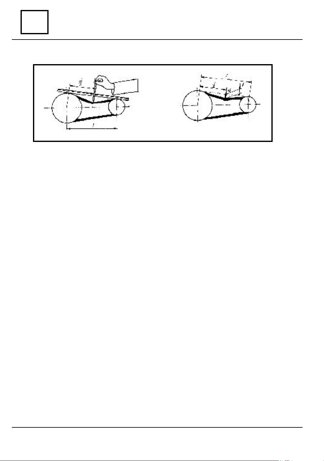
CHECK OF THE GASKET PLANE DEFORMATION
The checking of the deformation of the gasket plane is done by means of a ruler and of a set
of gauges.
The maximum accepted deformation is: x = 0,05 mm.
If the maximum deformation exceeds this value,the gasket plane is corrected by grinding.
Before grinding water pump and tilters platform are to be dismounted.
The cylinder head shall be carefully positioned on the grinding machine in order to observe the
parallelism of the surfaces.
DISMOUNTING - MOUNTING
because by reducing the height,the compression ratio is altered.
The maximum addition that may be ground: 0,5 mm.
If by grinding,the minimum accepted height is exceeded, the cylinder head is to be replaced
MOUNTING
Perform the dismounting operations in the reverse order.
10 - 30
Page 65

ENGINE AND LOWER ENGINE UNITS
vnx.su
DISMOUNTING - MOUNTING
PA RTICULARITIES UPON RE MOUNTING
The contact surfaces of the gasket must be
clean.
The grease or antifreeze fluid must be
removed from the holes of the cylinder head fixing screws by means of a.
This is necessary in order to obtain a
correct thightening of the screws and to avoid
the appearance of casing cracks.
Dismount t he MOT 484 device for jackets
attachments.
Place the gasket with the marking “HAUT”
or “TOP” upwards.
Check if the hole in the gasket correctly overlaps the lubrication channel in the block.
Set the cylinder head and the fixing screws.
Tighten the screws at the required moment: 6,5 daNm.
Mount the tilters shafts in the holes where they have been dismounted.
Adjust the acceleration pedal stroke.
Fill and aerate the cooling system.
Check and adjust the engine running.
10
CYLINDER HEAD REPLACEMENT
Dismount the cylinder head.
Dismount the spark plugs.
Dismount:
- the water pump pulley;
- the water pump;
- the ylinder head closing plate;
- the alternator support.
Set the MOT 320 plate for vales support.
10 - 31
Page 66

ENGINE AND LOWER ENGINE UNITS
vnx.su
10
Dismount the tilters platform.
Compress the valves springs by means of the
MOT 382 compressing device.
Take out the lock half cotters,release the
spring,take out the upper tray,the spring and the
lower tray.
Place the parts in order so that they may be
mounted back in the same place where they have
been dismounted from.
Remove the valves support plate,take out the
valves and set them in order.
Wa sh,clean and air blow the new cylinder
head.
DISMOUNTING - MOUNTING
performed when replacing the valves).
with the close coils towards the cylinder head.The end with close coils is marked with
green paint.
Check the presence of the lubricating channels and valves state.
Perform the lapping of the valves on the cylinder head guiding ( this operation is also to be
Mount the valves in the cylinder head and place the MOT 320 valves support plate.
Place in their previous positions:
- sealing gaskets of the valves shafts;
- the lower valve heads ;
- the valve springs;
- half cotters.
NOTE:
The valve springs are identical both for inlet and outlet.The springs are mounted
10 - 32
Page 67

ENGINE AND LOWER ENGINE UNITS
vnx.su
DISMOUNTING – MOUNTING
Compress the springs by means of the MOT 382 compression device and mount the lock
half cotters.
Mount the cylinder head closing plate and the water pump with new gaskets.
Mount the alternator support.
Mount the cylinder head with new gasket observing the mounting instructions.
Mount the tilter shafts in the place where they have been removed from.
Adjust the tilters.
Mount the tilters cap.
Adjust the acceleration pedal stroke.
Fill and aerate the cooling system.
Check and adjust the engine(ignition,carburation).
Retightem the cylinder head after 800 km of driving.
VA LV E SPRING REPLACEENT
Disconnect the battery.
Disconnect the acceleration cable.
Dismount the tilters cap.
Dismount the spark plug.
Mount the MOT 61 device for valve
maintaining in the place of the spark plug.
Dismount the tilter shaft.
( on car )
10
Compress the s pring by means of the
MOT 382 compressing device and take out the
lock half cotters.
Take out the upper tray and the spring.
Clean the seat of t he lower tray.
Place back in the previous site:
- new spring ( with the close coils
towards the cylinder head,the end marked with
green paint);
- the upper tray.
10 - 33
Page 68

ENGINE AND LOWER ENGINE UNITS
vnx.su
10
Compress the spring by means of the MOT 382 device and mount t he lock half cotters.
Mount the tilter shaft.
Adjust the tilter.
Mount the tilters cap.
The nuts tightening moment: 0,5 – 0,7 daNm.
Mount the acceleration cable and adjust the acceleration pedal stroke.
Dismount the MOT 61 valve support device and mount the spark plug.
Check and adjust the engine ( ignition,carburation).
REPLACEMT OF THE VALVE SHAFT SEALING R ING
Disconnect the battery.
Dismount the acceleration cable.
Dismount the tilters cap.
Dismount the spark plug.
Mount the MOT 61 valve supprt device in
the place of the s park plug.
Dismount the tilter’s shaft.
DISMOUNTING - MOUNTING
Compress the spring by means of the MOT
382 compression device and take out the lock
half cotters.
Remove:
- the upper tray;
- the spring.
Clean the seat of t he lower tray.
Dismount the sealing ring of the valve shaft using
the MOT 1335 device.
Mount the new sealing ring using the
MOT 250 device.
Re place at the previous place:
- the spring ( with the close coils towards
the cylinder head);
- the upper tray.
10 - 34
Page 69

ENGINE AND LOWER ENGINE UNITS
vnx.su
DISMOUNTING – MOUNTING
Compress the spring by means of the MOT 382 and mount the lock half cotters.
Mount the tilters shaft.
Mount the tilters cap.
The nuts tihtening moment is : 0,5 - 0,7 daNm.
Mount the accelerat ion cable and adjust the acceleration pedal stroke.
Dismount the valve maintainin device MOT 61 and mount the spark plug.
Check and adjust the engine (ignition,carburation).
TILT ERS PLATFORM ( on car )
ISMOUNTING
D
Disconnect the acceleration cable.
Dismount the tilters cap.
Dismount the platform from the cylinder head.
Dismount the lock clip from the shaft head.
10
ATTENTION:
Upon distension of springs,the parts
should not spring from the shaft.
Dismount the parts from the shaft and place
them in order.
Wash the parts observing the
Check the parts and replace t he deffective ones.
dismounting order.
10 - 35
Page 70

ENGINE AND LOWER ENGINE UNITS
vnx.su
10
REMOUNTING
Lubricate the supports,the tilters and the shaft
with clean oil.
Mount the parts on the shaft in the reverse
order of the operation performed for
dismounting.Pay attention that attachment holes
in the supports identify with the sockets on the
shaft.
Mount the assembled shaft on the cylinder
head and tighten it at the moment of
1,5 - 1,7 daNm . Adjust the tilters.
Mount the tilters cover.
Mount the acceleration cable and adjust the acceleration pedal stroke.
Check and adjust the engine(ignition,carburation)
DISMOUNTING - MOUNTING
NOTE:
Check the tihtening at the required moment of the tilters platform attachement nuts
and screws after every 10 000 km of driving before tilters adjustment.
VA L VES GUIDES REPLACEMENT
ISMO UNTING
D
Dismount the cylinder head from the
engine.
Dismount from the cylinder head the followings:
- the water pump;
- the valves;
- the valves shafts sealing rings;
- the tilters platform;
- the attachment bolts of the cap;
- the spark plugs.
Place the cylinder head on the
MOT 121 support plate and by means of the
MOT 148 device chuck (1) depress the
guiding on a hydraulic press.
10 - 36
Page 71

ENGINE AND LOWER ENGINE UNITS
vnx.su
DISMOUNTING – MOUNTING
Check the diameter of the depressed guiding:
- nominal value 11 mm ;
- value 1-st repair 11,1 mm;
- value 2-nd repair 11,25 mm;
NOTE: The guiding at the repair value are supplied only by request
EMOUNTING
R
Turn the cylinder head on the support plate
and bore the seat of the guide at the
correspondening value of the new guie.
10
Introduce the chuck (1) in the lock bushing
(2) (at one or the other side,depending on the
guiding being pressed) and the guiding is placed
on the end of the chuck (1).
Lubricate the uiding with oil and press it with
a hydraulic press observing the followings values:
- Inlet A = 26,5 mm;
- Oulet B = 26,2 mm.
These values are obtained during pressing;
in the moment when the shoulder
(1) reaches close the limiting bushing (2),the latter
is rotated until it comes into contact with the
chuck.
of the chuck
if
10 - 37
Page 72

ENGINE AND LOWER ENGINE UNITS
vnx.su
10
Bore the guiding at the value φ 7.
Grind the valve seat.
Perform the lapping of the valve with the valve seat.
Wash carefully the cylinder head and the component parts and blow them with air under pressure.
Mount on the cylinder head the following items:
- the cap attachment bolts;
- the valves shafts sealing rings;
- the valves(in the places where they have been removed from);
- the tilters platform;
- the water pump;
- the water pump pulley;
- the spark plugs.
Mount the cylinder head with a new gasket observing the mounting prescriptions.
Mount the acceleration cable and adjust the acceleration pedal stroke.
Perform the filling and aeration of the cooling system.
Perform the checking and adjustement of the engine running(ignition,carburation).
Retighten the cylinder head after driving 800 km.
DISMOUNTING - MOUNTING
10 - 38
Page 73

ENGINE AND LOWER ENGINE UNITS
vnx.su
DISMOUNTING – MOUNTING
VA LV E SEATS GRINDING
Dismount the cylinder head from the engine.
Dismount from the cylinder head:
- the water pump;
- the valves;
- the valves shafts sealing rings;
- the tilters platform;
- the cap attachment bolts;
- the spark plugs.
Place the cylinder head on the MOT 121
support plate.
Grind the valve seat by means of the MOT
287 tool for 102 engines and with MOT 501
tool for 106 engines observing the following
order:
- grind the working part (1) by means of the 45º cutter until the surface becomes clean and
shining on the whole circumference;
- take the new or the ground valve,marked on the working surface with paint or carbon
paper and place it on the seat;
- rotate the valve,take it out and check the mark left by the valve;
0
- according to the mark left,the surface ( 2) by means of the 15
means of the 70 º cutter until the working surface is the prescribed one
( 1,1 - 1,4 mm for inlet and 1,4 - 1,7 mm for outlet ) and the mark left on the valve is halfway the
working surface of the latter.
Perform the lapping of the valve or of the valves,then place them in order so that they can be
mounted in the place they have been taken out.
Carefully wash the cylinder head and the valves and air blow them.
Check the valves sealing by means of gasoline.
Mount the following items:
- the tilters platform;
- the cap attachment bolts;
- the valves shafts sealing rings;
- the valves;
- the water pump;
- the spark plugs.
Mount the cylinder head on the engine with a new gasket observing the mounting
prescriptions.
Mount the acceleration cable and adjust the acceleration pedal stroke.
or surface (3) is ground by
10
10 - 39
Page 74

ENGINE AND LOWER ENGINE UNITS
vnx.su
10
Perform the filling and aeration of the cooling system.
Perform the checking and adjustment of engine operation (ignition,carburation).
Re tighten the cylinder head after driving 800 km.
ENGINE KIT REPLACEMENT ( on car )
DISMOUNTING - MOUNTING
D
the engine.
of the connecting rods is done on the side opposite the camshaft.
ISMO UNTING
Disconnect the battery.
Drain the cooling ci rcuit and the oil from
Dismount:
- the tilters cap;
- the cylinder head;
- the oil sump;
- the oil pump.
Identify the connecting rods: connecting rod no. (1) is the one on the flywheel side.The marking
Dismount:
- the connecting rods caps;
- the bushings;
- the engine kit ( jackets – pistons – connecting rods ).
the places where they have been removed from.
scrapper).
- the state of the cylinder head ( grind the gasket surface,the seats,perform the lapping
of the valves if necessary ).
NOTE:
The caps and the bushings shall be placed in order so that they may be mounted in
Clean and air blow the parts ( it is forbidden the cleaning of the aluminium parts by means of a
Check: - the state of the oil pump ( to be repaired or to be replaced if it is used).
10 - 40
Page 75

ENGINE AND LOWER ENGINE UNITS
vnx.su
DISMOUNTING – MOUNTING
NOTE: The parts contained in the repair
kit are in pairs ( jackets-piston-piston shaft )
according to colours.
The colour (1) marked on the piston head
must correspond to the colour marked on the
jacket.
The colour (2) marked represents the piston
weight and must be the same for all the pistons.
The colour (3) marked on the piston head
must correspond to the one marked on the head
of the piston shaft.
The piston-jacket clearance 0,045 - 0,065
valid for new pistons and valves).
mm (
The measurement of the piston is done in
the area ( see the figure) in perpendicular plane
on bolt hole axle.
The masurement of the jacket is done in two
separate sections ( see the figure) in perpen-
lar plane wit h external flatteni ngs. For
dicu
calculation
average diameter ( D ) is to be considered:
of the piston – jacket clearance
the
D = D1 + D2
2
D1
D2
zonã de
mãsurare
THE HEIGHT OF THE JACKETS OVER THE GASKET LEVEL
10
The checking of the jackets height over the gasket level is performed by means of the MOT
252 setting plate, the MOT 251 support and a comparison item.
For the engines with the sealing of the
cylinder jackets by “ 0” ring, the checking is done
without the gasket. At these engines,the rubber
gasket is used only for sealing.
The height of the jackets over the level of the
gasket is:
0,02 - 0,09 mm
Place the jackets without gaskets in their
respective seats in the block.
Measure the height of the jackets over the
gasket level.
If the height of the jackets over the
gasket level is not within the prescribed limits,the
jacket-block assembling values are to be checked.
10 - 41
Page 76

ENGINE AND LOWER ENGINE UNITS
vnx.su
10
For all types of engines,the jackets shall be positioned as follows:
- the maximum difference between the heights of two adjoing jackets shall be
maximum 0,02 mm,within the limit of the prescribed tolerance;
- the jackets shall be placed in growing order ( by steps ).
After obtaining the correct height,the position of the jackets in the block is marked so that it
may be paired with the corresponding connecting rods.
For the engines where sealing is done by “ Cu “ made gaskets,the checking is done with
gaskets fitted.
Overheight of the gaskets over the gasket level : 0,05 – 0,13 mm. If the height of the jackets
over the gasket level is not within the prescribed limits, the jacket-block assembling values are to
be checked.
DISMOUNTING OF THE PISTON SHAFT
The dismounting and mounting of the piston
shafts is performed by means of the MOT 255
device ,made of:
- support bushing of the piston upon
dismounting the piston (A);
- support bushing of the piston upon
mounting (B);
- extractor mandrel (3);
- mounting mandrel (1);
- centering mandrel (2);
- connecting rod checking mandrel (4);
- washer (5).
Place the old piston with the blades it em on
the support bushing (A).
Introduce the extractor mandrel (3) and by
means of a press, dismount the shaft of the old
piston.
DISMOUNTING - MOUNTING
CONNECTIONG RODS PREPARATION
Check:
- the state and the aspect of the connecting rods;
- the setting of the cap on the connecting rod body; remove the burrs if any in order to
ensure a correct setting;
- the parallelism of the head and the foot;
- the connecting rod twist.
10 - 42
Page 77

ENGINE AND LOWER ENGINE UNITS
vnx.su
DISMOUNTING – MOUNTING
NOTE:
If wear of the connecting rods is noticed or if the parallelism of the shafts is not
correct, the connecting rods shall be corrected or replaced.
For the new connecting rods, a check shall be made so that they belong to the same
weight class (they shall not have the same colour marked on them).
PREPARATION OF THE PISTON SHAFT
Check if the piston shafts rotate freely in the
corresponding pistons.
Mount shaft on the mounting mandrel (1);
the pistons shaft shall freely rotate on the mandrel.
Mount the centering mandrel (2) on the
mounting mandrel (1).
Grease the mandrel-piston shaft assembly
with special grease containing MoS
PISTON – CONNECTING
2.
10
ROD PISTON SHAFT ASSEMBLY
Use an electric plate of 1500 W.
(electric oven)
Heat the crosshead end of the connecting
in the furnace at a temperature of about 250°C
(10 – 15 minutes) in order to increase the boring of the connecting rod crosshead end by dilatation.
The temperature is checked by placing a piece
of tin (a) on the crosshead of the
connecting rods; heat the connecting rods until
the tin melts.
On the piston head there is an arrow marked
which must be oriented towards the flywheel.On
the oposite side of the piston there is a bladed
item on which the piston lay when the piston shaft
is mounted.
rod
10 - 43
Page 78

ENGINE AND LOWER ENGINE UNITS
vnx.su
10
When assembling the piston with the connecting rod,the following instructions are to be
observed:
- place the piston with the bladed item on the bushing (B) of the piston shaft mounting device;in
this situation the arrow on the piston head shall be upwards oriented;
- place the connecting rod on the piston with the marking or with the slots for bushings oriented
towards the right side of the worker; in this situation when mounting the assembly in the block
the arrow shall be oriented towards the flywheel and the marking on the connecting rod will be
on the opposite side of the camshaft.
NOTE: The following operations are to be performed very quickly to avoid the
connecting rod cooling.
When the connecting rods reached the tem-
perature of 250 °C ( the tin is melted):
- remove the tin from the crosshead end
of the connecting rod;
- place the connecting rod in the piston
observing the positioning indications of the latter;
- quickly introduce the mounting mandrel
(1) with the piston shaft until the
latter comes into contact with the bottom of the
support bushing;
- dismount the chuck from the piston shaft;
check if the piston shaft remains retracted as to
the piston disregard of the connecting rod position.
DISMOUNTING - MOUNTING
towards the piston head;
and the piston;
the lubricating ring shall be obligatory on the side
of a fill of its channel and at 90 º as to the piston
shaft.
NOTE: On the bottom of the support bushing shall be placed a 1,5 mm.
ASSEMBLING SET MOTOR
Mount on the piston:
- the lubricating ring;
- the sealing rin with the marking “ TOP “
- the compression ring.
Abundantly lubricate with fresh oil the rings
0
Displace the rings s lots at 120
; the s lot of
10 - 44
Page 79

ENGINE AND LOWER ENGINE UNITS
vnx.su
DISMOUNTING – MOUNTING
Lubricate the jackets with fresh oil.
Mount in the jackets the piston-connecting rod assembly with the bushing:
- MOT 502 for 102 engines;
- MOT 655 for 106 engines.
When mounting, the connecting rod sides will be parallel w ith the flattenings made on the
jackets.
Mount the sealing gaskets on the jackets.
Mount the bushings on the connecting rods.
Place the connecting rod-piston-jacket assembly in the block ; observe the correct
positioning:
- cylinder (1) towards the flywheel;
- the marking on the connecting rod opposite to the camshaft;
- the arrow on the piston head shall be oriented towards the flywheel.
Mount the the jackets maintaining device MOT 484.
Oil the the bushings and the crankshaft with fresh oil.
Place the connecting rods on the bearings and mount the caps.
Tihten the cap nuts at the required moment of 4.5 daNm with dynamometric w rench.
Check the correct rotation of the mobile assembly.
Dismount the device for jackets maitaining.
Mount:
- the oil pump;
- the oil sump;
- the cylinder head; adjust the tilters;
- the breaker-distributor; adjust the ignition.
Perform :
- oil filling of the engine;
- filling and aeration of the coolin system.
10
10 - 45
Page 80

ENGINE AND LOWER ENGINE UNITS
vnx.su
10
OIL PLATFORM PLUGS REPLACEMENT
D
ISMO UNTING
Dismount the plugs from the block by boring with a φ 10 drill.
Wash the block,clean the platform and the channels in the block and blow it with compressed
air.
EM
R
OUNTING
Oil the new plugs with OMNI - FIT
RAPID.
Place the plugs (1) in their seats in the block
and clamp them by means of the
MOT 111A rivet set.
DISMOUNTING - MOUNTING
REPLACEMENT OF THE CRANKSHAFT BEARING ANNULAR OIL SEAL
ISMO UNTING
D
Disconnect the battery.
Dismount:gearbox,clutch mechanism and
the disk,flywheel and the worn annular oil seal.
EMOUNTING
R
Place the new annular oil seal on the
MOT 259 - 01 mounting device.
Lubricate with oil the exterior diameter of the
annular oil seal.
ATTENTION:
The edge of the annular oil seal is very
fragile:take protection steps upon mounting.
10 - 46
Page 81

ENGINE AND LOWER ENGINE UNITS
vnx.su
DISMOUNTING – MOUNTING
Mount the annular oil seal in its place,slightly
tapping the chuck head until it comes into contact
with the crankshaft.
The mounting chuck for the annular oil seal
shall be kept w ith care i n order to avoid
deterioration of the collar on which the
annular oil seal is placed.
Protect t he chuck by placing a worn annular
oil seal on it.
Mount the flywheel.the screws will be
lubricated with FIXAMED M 28.
Tighten the screws at a 5 daNm moment.
Center the disk by means of the centering chuck and mount the clutch mechanism.
Mount the gear box.
Check all the fluid fillings and perform all necessary adjustments.
10
REPLACEMENT OF THE C LUTCH SHAFT CENTERING BUSHING
ISMO UNTING
D
Disconnect the battery
Dismount:
- gear box;
- clutch mechanism and the disk;
- the worn bushing by means of the
MOT 101 extractor.
10 - 47
Page 82

ENGINE AND LOWER ENGINE UNITS
vnx.su
10
EMOUNTING
R
Press the new bushing by means of the clutch
disk centering chuck.
Center the disk by means of the centering
chuck.
Mount the clutch mechanism.
Mount the gear box.
Check all the fluid fillings and perform all
necessary adjustments.
DISMOUNTING - MOUNTING
CRANKSHAFT REPLACEMENT
ISMO UNTING
D
Dismount the engine from the car.
Mount the engine on the MOT 369 support.
Drain the oil off the engine.
Dismount:
- the alternator and the attachment clip;
- the fuel pump;
- the oil filter;
- the oil dip stick;
- the breaker -distributtor and the ignition cables;
- the contact and oil pressure transmitter;
- the left side s upport and the elastic buffer.
Mount the MOT 460 device bolts on the
engine block.
10 - 48
Page 83

ENGINE AND LOWER ENGINE UNITS
vnx.su
DISMOUNTING – MOUNTING
Place the e ngine on the MOT 460
suPlace the engine on the MOT 460
support.pport.
Dismount:
- the press ure plate and the clutch disk;
- the breaker-distributtor pinion by means
of a M 12 x 1,5 screw.
Rotate the engine by 180 º and dismount the
following parts:
- the crankshaft pulley;
- the oil casing;
- the oil pump;
- the distribution cap.
Take out the sealing gaskets of the dismounted
items or remove the sealant material by scrappimg
it, for those with sealant sealing.
10
Dismount the distribution chain tightening
device.
Strain the lock washer and unscrew the camshaft pinion fixing screw.
Take out the camshaft pinion and the
distribution chain.
10 - 49
Page 84

ENGINE AND LOWER ENGINE UNITS
vnx.su
10
Take out the cranks haft pinion by means of
the MOT 49 device.
Dismount the engine flywhhe.
Check the marking of the connecting rods:
- no.1 towards the flywheel and opposite
to the camshaft.
Unscrew the connecting rod caps nuts.
Dismount the connecting rods cas and the half
bushings and place them in order.
DISMOUNTING - MOUNTING
bushings and place them in order.
Dismount the crankshaft.
Dismount the connecting bearing and the half
Dismount the crankshaft.
10 - 50
Page 85

ENGINE AND LOWER ENGINE UNITS
vnx.su
DISMOUNTING – MOUNTING
Remove the half bushings from the
connecting rod and from the block and put them
in order.
Dismount the washer thrusts for the axial
clearance adjustment.
Remove the annular oil seal from the bearing.
REMOUNTING
Wash and air blow the new crankshaft; check the existence of the lubricatin holes in the shaft.
Clean the contact surface of the gasket to the block a nd oil s ump.
Mount the half bushings on the connecting rods.
Mount the half bushings of the bearings in the blck ( the half bushings with lubricating holes).
10
NOTE:
The half bushings of bearings 1 and 3 on one hand and the ones for bearings 2 , 4
and 5 on the other hand,are identical.
In case crankshaft is replaced, it is obligatory to change also the connecting rod
bearings, crankshaft bearings and the distribution and bearing annular oil seals.
Mount the crankshaft pinion on the shaft.
Lubricate with fresh oil the followings:
- the bushing of the bearings;
- the bearings of the crankshaft;
Mount the crankshaft.
Lubricate with oil the axial half bushings and
mount them in their respective seats.
10 - 51
Page 86

ENGINE AND LOWER ENGINE UNITS
vnx.su
10
Mount the half bushings on the bearing
heads ( the half bushings for caps do not have
lubricating holes).
Lubricate the half bushings with fresh oil and
mount the bearing caps at their place
according to the marking.
It is obligatory to degrease the contact
surfaces of the no.1 bearing cap and then to apply
a layer of LOCTITE 518 in order to ensure the
sealing.
Tighten the attachment screws of the caps at
5,5 – 6,5 daNm moment us ing.
Check the free rotation of the crankshaft.
DISMOUNTING - MOUNTING
Mount a support with magnetic bottom and
by means of a comparator check the axial clearance of the crankshaft which must be within 0,05
and 0,23 mm.
If the clearance is not as required,replace the
axial half bushings.
The axial half bushings have various thickneses
such as: 2,28 ; 2,38 ; 2,43 mm .
Mount the bearing annular oil seal on the
MOT 259-01 chuck.
Lubricate the outside of the annular oil seal
with oil and mount it in its seat by slightly tapping
the head of the chuck until the latter comes into
contact with the crankshaft.
10 - 52
Page 87

ENGINE AND LOWER ENGINE UNITS
vnx.su
DISMOUNTING – MOUNTING
NOTE:
In case the old crankshaft is to be mounted, displace the annular oil seal position by
inserting a 2 mm thick washer between the chuck and the crankshaft end so that the
annular oil seal does not work in its initial position.
Mount the flywheel using new screws.Before
mounting lubricate with FIXAMED M 28 the
screws.
Tighten the screws at a 5 daNm moment
using.
10
Mount the support with magnetic bottom and
by means of a comparator check the axial runout
of the flywheel. The maximum admitted runout:
0,06 mm.
Mount the half bushings in the connecting rods
caps.
Lubricate the half bushings and the bearings
with oil and mount the connecting rod
caps.Tighten the s crews at a 4.5 daNm
moment using.
Check the free rotation of the mobile
assembly.
10 - 53
Page 88

ENGINE AND LOWER ENGINE UNITS
vnx.su
10
DISMOUNTING - MOUNTING
Mount : the il pump and the distribution,the oil sump and the distribution cap with new gaskets
or sealant, the disk and mechanism clutch.
Place the engine on MOT 369 support and mount :
- the left side support and elastic buffer;
- the anometer and the oil pressure transmitter;
- the oil filter;
- the oil dip stick;
- the drive pinion of the breaker- distributtor, the breaker- distributtor and the spark
plugs cables;
- the fuel pump;
- the attachment clip and the alternator.
Mount the engine on the vehicle.
Perform:
- the oil filling of the engine;
- the filing and aeration of the cooling circuit;
- engine checking and adjustment ( ignition,carburation).
10 - 54
Page 89

ENGINE AND LOWER ENGINE UNITS
vnx.su
REPLACEMENT OF THE DISTRIBUTION ANNULAR OIL SEAL
ISMO UNTING
D
Disconnect the battery.
Place the no.1 cylinder at the dead point in
orde to avoid the falling of the key from the
crankshaft when disounting the crankshaft pulley.
Dismount :
- engine shield;
- alternator belt;
- crankshaft pulley.
Dismount the old annular oil seal by means of
the MOT 457 A device.
R
EMOUNTING
Mount the new annular oil seal on the mount-
ing chuck of the MOT 457 A device.
Lubricate the outside of the annular oil seal
with oil and place it on the cap.
Tighten the nut until the chuck comes into
contact with the cap.
Mount:
- the crankshaft pulley after the
surface between the pulley hub and the
distributtion pinion has been lubricated with
LOCTITE 518
Mount the alternator belt and adjust its
tightness.
.
10
10 - 55
Page 90

ENGINE AND LOWER ENGINE UNITS
vnx.su
10
DISTRIBUTION CAP REPLACEMENT
D
ISMO UNTING
Disconnect the battery.
Drain the oil off the engine.
Dismount the alternator belt, the water pump
pulley and the engine shield.
Dismount the oil sump: (adjust the engine with
no.1 and 4 pistons in the lower dead point), rotate
the front part of the oil sump towards the left and
lower it.
DISTRIBUTION CAP
Dismount the crankshaft pulley.
Dismount the distribution cap.
Dismount the annular oil seal from the cap.
Clean the contact surfaces of the gaskets or
those where sealant material has been
applied (engine block, oil sump, distribution cap).
10 - 56
Page 91

ENGINE AND LOWER ENGINE UNITS
vnx.su
DISTRIBUTION CAP
10
REMOUNTING
Mount the distribution annular oil seal.
Place the cap with new gasket or on the block after sealant material has been applied previously.
Center the cap by means of the MOT 457 A device.
Attach the cap on the block; the tightenin of the s crews is done from the upper part towards
the lower part.
Re mount the crankshaft pulley,the water pump pulley, the alternator belt.
Place:
- the rubber gaskets of the bearings;
- the side gaskets of the oil sump.
In case sealant material is used , this is to be applied as per bellow described procedure.
Mount the oil sump taking care not to displacethe gaskets ot the sealant material.
Tighten the attachment screws from the center towards the edges.
Re mount the engine shield.
Perform the filling with oil of the engine.
For engines fitted after 01.06.1999 the sealaing of the distribution cap is done with sealant
material ( instead of the distribution cap gasket ),the necessary quantity of sealant material is 15
grams.
Any dismounting of the distribution cap nrequires the replacing of the sealant material layer.
Proceed as follows:
Remove the old sealant material by scrapping with a knife from the contact surface of the
distribution cap and engine casing.
10 - 57
Page 92

ENGINE AND LOWER ENGINE UNITS
vnx.su
10
Clean with 002 solvent the contact surfaces of the engine casing and of the distribution cap .
Place a continous sealant material layer of a 3 mm thickness on the lower part of the contact
surface of the distribution cap,taking care not to obturate the its fixing holes.
Mount the distribution cap and tighten the attachemnt screws at the required moment.
Mounting of the distribution cap on engine casing must be done in maximum
DISTRIBUTION CAP
ATTENTION !
5 minutes from the sealant material application.
At the distribution cap which is mounted with sealant material, the drawings of the
contact surface are towards the exterior ( see chapter
mounted with gaskets where the drawings are towards the interior.
The distribution cap mounted with sealant material can not be mounted with gaskets
and the ones mounted with gasketes can not be mounted with sealant material.
A - A ) different from the ones
10 - 58
Page 93

ENGINE AND LOWER ENGINE UNITS
vnx.su
TIGHTENER AND DISTRIBUTION CHAIN
REPLACEMENT OF TIGHTENER AND DISTRIBUTION CHAIN
D
ISMO UNTING
Disconnect the battery.
Drain the oil from the engine.
Dismount: the engine shield,the cross bar
between the longitudinal girders,the elastic
bushing nuts of the stabilizer rod,the alternator
belt,the fan and the water pump pulley,the oil
sump and the distribution cap.
Unscrew the tightener fixing screw.
Dismount the tightener.
ATTENTION !
Do not let spring the crosshead shoe and
the spring .
10
Straighten the lock washer and unscrew the
camshaft pinion fixing screw.
Take out the camshaft pinion and the
distribution chain.
Clean the contact surfaces of the gaskets
( engine block,oil sump,distribution cap ).
EMOUNTING
R
( Distribution adjustment )
Mount the camshaft pinion so that markings
on the pinions to be placed one in front of the
other and to be collinear with pinion centers.
Dismount the the camshaft pinion avoiding
rotation.
its
10 - 59
Page 94

ENGINE AND LOWER ENGINE UNITS
vnx.su
10
TIGHTENER AND DISTRIBUTION CHAIN
Place the new chain on the camshaft pinion
and on the crankshaft pinion.
Mount the camshaft pinion maintaining the
alignement of the markings on the pinions.
Tighten the fixing screw at a 2 daNm
moment and strain the safety washer.
Mount the tightener performing the
dismounting operations in the reverse order:
1.Tightener crosshead shoe.
2. Spring
3. Shaft
4. Tightening washer
5. Fixing screw and washer
using this sealing with sealing material);
be greased with LOCTITE 518);
- filling and aeration of the cooling circuit.
Remount:
- the distribution cap and the oil sump with new gaskets; (using sealant material for engines
- the crankshaft pulley; (the surface between the pulley hub and the distribution pinion will
- the water pump pulley and the fan;
- the elastic bushings fixing attachments nuts of the stabilizer rod;
- the crossbar between the longitudinal girders;
- the engine shield.
Mount the alternator belt and adjust its tighteness.
Mount the radiator.
Perform : - oil filling of the engine;
10 - 60
Page 95

ENGINE AND LOWER ENGINE UNITS
vnx.su
CAMSHAFT
10
CAMSHAFT REPLACEENT
ISMO UNTING
D
Disconnect the battery.
Drain: oil from engine and the cooling circuit.
Dismount :
- air filter,front grill,radiator,crossbar betwenn the longitudinal girders,the fixing nuts of the
elastic bushers from the stabilizer rod.
Dismount the breaker- distributtor,the tilters cap,the cylinder head,the tilters shafts and the
pushers;arrange them in order so that they may be re mounted in the places they have been
removed from.
Mount the jackets maintaining device MOT 484.
Dismount the fuel pump without disconnecting the hoses,the control pinion of the breaker
distributor with a cylinder head attachement screw,the engine shield,the crossbar between the
longitudinal girders,the elastic bushings at tachement nuts of the s tabilizer rod,the oil sump,the
alternator belt,the water pump pulley and the fan,the crankshaft pulley,the
distribution cap,the distribution chain tightener,the camshaft pinion and the distribution chain.
Dismount:
- the fixing screws of the camshaft clip;
- the camshaft.
Clean the contact surfaces of the gaskets ( engine block,oil sump,distribution cap,cylinder
head ).
10 - 61
Page 96

ENGINE AND LOWER ENGINE UNITS
vnx.su
10
CAMSHAFT
REMOUNTING
Mount on the new camshaft : the disk key,a new attachement clip,a new cross piece;tapp the
cross piece with a rod until it comes i nto contact with the camshaft shoulder).
Mount the camshaft pinion and tighten the screw at the moment of 3 daNm using.
Check the attachement clip cleara nce ( J ) ; the c leara nce must be between 0,06 and 0,11
mm.
If clearance is not the required one, replace the clip.
distribution cap with a new gasket or sealant material,the crankshaft pulley,the water pump pulley
and the fan,the oil sump with new gaskets or sealant material for engines assembled after
01.06.1996,the elastic bushings attachement nuts on stabilizer rod,the crossbar between the
longitudinal girders and the engine shield.
Dismount the camshaft pinion.
Lubricate with oil the camshaft and mount it in its place.
Tighten the screws of camshaft clip fixing at a 2 daNm moment.
Remount: the camshaft pinion and the distribution chain,the distribution chain tightener, the
10 - 62
Page 97

ENGINE AND LOWER ENGINE UNITS
vnx.su
CAMSHAFT
10
Mount the control pinion of the breaker distributor.
The control pinion is positioned as follows:
- place the no.1 cylinder at the upper dead point, on ignition;
- mount the pinion with a cylinder head attachement screw so that the slots are
perpendicular on the engine longitudinal axle and the larger part ( D) is oriented towards the
flywheel.
Re mount the pushers lubricated with fresh oil,the cylinder head ,the tilters shafts.
Adjust the tilters ( thermal clearance ) at cold :
- inlet - 0,15 mm ;
- outlet - 0,20 mm.
Mount the tilters cap.
Mount the fuel pump,the breaker-distributor.
Re mount the radiator ,the front grill ,the air filter.
Mount the alternator belt and adjust its tightening.
Perform: oil filling of the engine,filling and aeration of the cooling system,engine
checking and adjustement ( ignition,carburation ).
10 - 63
Page 98

ENGINE AND LOWER ENGINE UNITS
vnx.su
10
OIL SUMP DISMOUNTING – REMOUNTING
ISMO UNTING
D
Disconnect the battery.
Drain the oil off the engine.
Dismount: engine shield and oil sump
attachement screws.
Place the crankshaft with pistons 1 and 4 to
the lower dead point.
Rotatethe front parts of the sump to the left
and lower it.
Clean the contact surfaces of the gaskets
(engine block,oil sump) or those where sealant
material has been applied.
LOWER CRANKCASE
REMOUNTING
Place :
- the rubber gaskets of the bearings;
- the s ide gaskets of the sump;
( sealant material on oil sump for engines fitted
after 01.06.1996 )
- place the oil sump so that the gaskets or
sealant material layer are not displaced;
- tighten the sump attachement screws from
the middle towards edges;
- tighten the oil sump attachment nuts;
- perform the oil filling of the engine.
For engines fitted after 01. 06. 1996 the sealing of the oil sump is done by means of sealant
material ( instead of oil sump gaskets).
Any dismounting of the oil sump requires replacement of the sealant material layer.
The sealant materials homologated by SC AUTOMOBILE DACIA SA, are the followins:
- RHODOR SEAL 5661;
- LOCTITE 5900 ( ULTRA BLAKE ).
10 - 64
Page 99

ENGINE AND LOWER ENGINE UNITS
vnx.su
LOWER CRANKCASE
The quantity of sealant material necessary for one engine is max. 60 grams, of which max. 15
grams for the distribution cap and max. 45 grams for oil sump.
Proceed as follows:
Remove trhe oil sump.
Remove the old sealant material using a knife by scrapping , from the contact surface a of oil
sump and enine casing.
Clean with 002 solvent the contact surfaces of the engine casing and the oil sump.
Place a continous layer of sealant material of a 3 mm thickness on the interior part of the oil
sump contact surface ta king care not to obturate its fixing holes.
Mount the oil sump and tighten the attachement screws at the required moment.
10
ATT EN TI ON !
The oil sump mounting on engine casing must be done in maximum 5 minutes from
sealuing matterial application.
For the oil sump which is sealed with sealant material,the drawings of the contact
surface are towards the exterior, different from the ones mounted with gaskets where
the drawings are towards the interior.
The oil sump mounted with sealant material can not be mounted with gaskets and
the ones mounted with gasketes can not be mounted with sealant material.
10 - 65
Page 100

ENGINE AND LOWER ENGINE UNITS
vnx.su
10
OIL PUMP DISMOUNTING – REMOUNTING
ISMO UNTING
D
Disconnect the battery.
Drain the oil off the engine.
Dismount :engine shield,crossbar between the longitudinal girders,elastic bushing nuts on the
anti rolling shaft and the oil pump.
Unscrew the attachement screws and take out the oil pump.
Clean the contact surfaces of the gaskets or those with sealant material ( engine bloc and oil
sump).
EMOUNTING
R
Mount the new oil pump with a new gasket.
Τighten the attachment screws.
Remount:
- the oil sump;
- the bearing attachement nuts to stabilizer rod;
- the crossbar between the longitudinal girders;
- the engine shield.
Perform the oil filling of the engine.
OIL PUMP
10 - 66
 Loading...