


INSTALLATION and SERVICE INSTRUCTIONS
USE and CARE INSTRUCTIONS
distributed by
DèLonghi
Pty Ltd
DOMINO
INDUCTION HOB
model DE302IB

Dear Customer,
Thank you for having purchased and given your preference to
our product.
The safety precautions and recommendations reported below are
for your own safety and that of others. They will also provide a
means by which to make full use of the features offered by your
appliance.
Please keep this booklet in a safe place. It may be useful in
future, either to yourself or to others in the event that doubts
should arise relating to its operation.
This appliance must be used only for the task it has explicitly
been designed for, that is for cooking foodstuffs. Any other
form of usage is to be considered as inappropriate and
therefore dangerous.
The manufacturer declines all responsibility in the event of
damage caused by improper, incorrect or illogical use of the
appliance or be faulty installation.
PRODUCT LABEL
PRODUCT LABEL
This cooktop has been designed and constructed in accordance with the following
codes and specifications:
AS/NZS 60335.1 General Requirements for Domestic electrical appliances
AS/NSZ 60335.2.6 Particular Requirements for Domestic electrical cooking appliances
AS/NZS CISPR 14.1 Electromagnetic Compatibility Requirements.
2

BEFORE USING FOR THE FIRST TIME
• Read the instructions carefully before installing and using the appliance.
• After unpacking the appliance, make sure it is not damaged. In case of doubt, do not
use the appliance and contact your supplier or a qualified engineer.
• Remove all packaging and do not leave the packing material (plastic bags, polystyrene, bands etc) in easy reach of children as they may cause serious injury. The packaging materials are recyclable.
• The appliance should be installed and all the electrical connections made by a qualified engineer in compliance with local regulations in force and following the manufacturer’s instructions.
• Do not attempt to modify the technical properties of the appliance, as it may become
dangerous to use.
3

IMPORTANT SAFEGUARDS & RECOMMENDATIONS
• Do not carry out any cleaning or maintenance without first disconnecting the appliance
from the electrical supply.
• During and after use of the hob, certain parts will become hot. Do not touch hot parts.
• After use always ensure that the controls are in the OFF position.
• Household appliances are not intended to be played with by children.
• Keep children away from the hob during use.
• Children, or persons with a disability which limits their ability to use the appliance,
should have a responsible person to instruct them in its use. The instructor should be
satisfied that they can use the appliance without danger to themselves or their surroundings.
• WARNING
When correctly installed, your product meets all safety requirements laid down for this
type of product category. However special care should be taken around the underneath of the appliance as this area is not designed or intended to be touched and may
contain sharp or rough edges, that may cause injury.
• Fire Risk! Do not leave inflammable materials on the Hob top.
• Make sure that electrical cords connecting other appliances in the proximity cannot
come in to contact with the Hob top.
• Do not allow heavy or sharp objects to drop on the glass ceramic hob.
• Do not scratch the hob with sharp objects. Don’t use the hob as a work surface.
• Before disposing of an unwanted appliance, it is recommended that it is made inoperative and that all potentially hazardous parts are made harmless.
• Important: This appliance has been designed for domestic use only. The appliance
is NOT suitable for use within a semi-commercial, commercial or communal environment.
• If the supply cord is damaged, it must be replaced by the manufacturer or its ser-
vice agent or a similarly qualified person in order to avoid a hazard.
• Do not operate your appliance by means of an external timer or separate remote-control system.
• Do not place or leave empty pans on the glass ceramic hob.
• Metallic objects such as knives, forks, spoons and lids should not be placed on the
hob surface since they can get hot.
• Do not use metallic kitchen utensils (e.g. ladles). It is preferable to use plastic or wood
kitchen utensils.
• Please use pans of recommended size (see minimum pan diameter recommended).
It is not advisable to use pans smaller than the cooking zone. The pans have to be
placed in the centre of the cooking zone.
• Do not use defective pans or pans with a curved bottom.
• Please use suitable pans marked for induction cooking.
• Please keep your distance from the electromagnetic fields by standing 5-10 cm from
the cooking zones.When possible use the rear cooking zone.
• Magnetic objects (e.g. credit cards, floppy disks, memory cards) and electronic instruments (e.g. computers) should not be placed near the induction hob.
• IMPORTANT WARNING: The induction hob complies with the applicable Standards
for domestic cooking appliances. Therefore it should not interfere with other
electronic units. Persons with cardiac pacemakers or any other electrical
implants must check with their doctor if they can use an induction cooking system (and check any possible interferences with the implants).
• Attention: Detach the appliance from the mains if the ceramic glass is cracked
and contact the After-Sales Service.
4
1
FEATURES AND TECHNICAL DATA
2
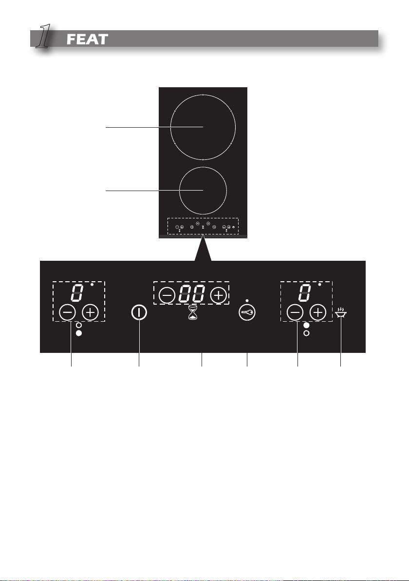
1
Fig. 1.1
4 7
Electrical insulation Class I
COOKING ZONES
1. Induction cooking zone Ø 140 mm - 1400 W
2. Induction cooking zone Ø 210 mm - 2200 W (3000 W with Booster function)
TOUCH-CONTROL DESCRIPTION
3. ON/OFF key
4. Front zone (1) keys (increasing and decreasing power)
5. Rear zone (2) keys (increasing and decreasing power)
6. Booster function (rear zone only) (2)
7. Automatic cooking timer keys
8. Child lock selection
3
8 5 6
5
2
Notes:
– Each selection (by pressing one of
the keys) is indicated by an acoustic
signal (beep).
– User interface initial calibration: this
feature is for the keyboard calibration,
to adapt the sensibility of the keys to
the final mechanical, environmental
and user conditions.
Any time the cooktop is connected to
the electrical supply or after a power
failure (that generates a reset in the
user interface), the first time the KeyLock is touched the sensibility of
the keyboard is readjusted.
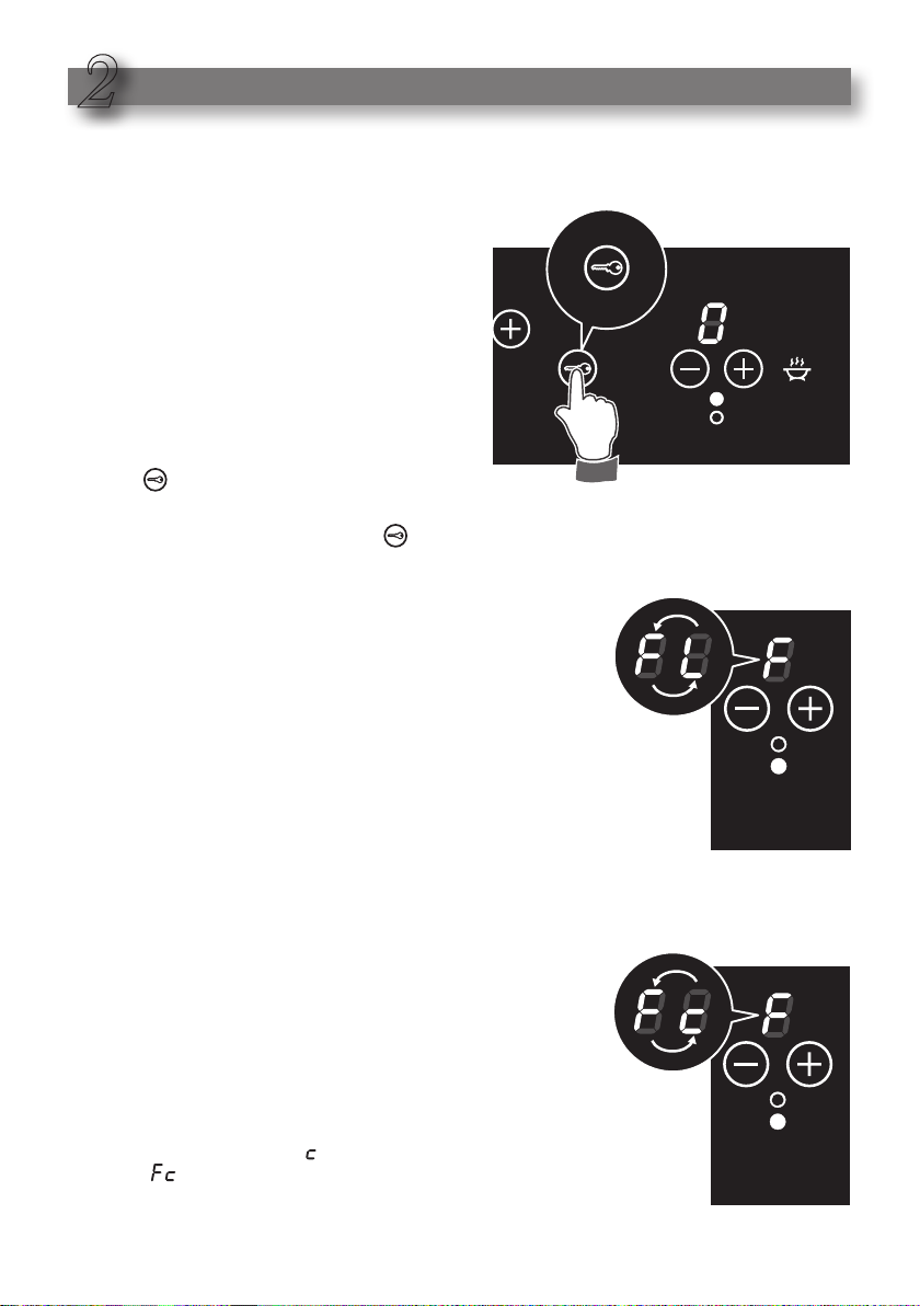
The first touch of the Key-Lock must be done
in certain condition: do not use gloves, use a clear
finger.
It is also important to consider that the calibration
process requires a low level of ambient light in the
area of the touch keys. If the environmental light
conditions are excessive (e.g. halogen hood light/s
on), the user interface calibration is suspended and
the cooking zones displays show “F ” and “L ” alternating - error message “ FL ”) until the correct light
conditions will be recovered.
In this case the direct environmental light/s must be
switched off before calibrating the cooktop; then,
after completing the process, the light/s can be
switched on again.
USE OF INDUCTION HOB
– The touch control is switched off automatically (and
a warning beep sounds every 10 seconds):
• if one or more keys are touched for more than 10
seconds;
• if an object is positioned on the touch control
area;
• in the case of spillage of liquids on the control
keys.
– When the touch control reaches an ambient tem-
perature above a preset temperature the heating
elements are automatically switched off (the displays show “ F ” and “ ” alternating - error message “ ”). In this case let the cooktop cool down
before using again.
6
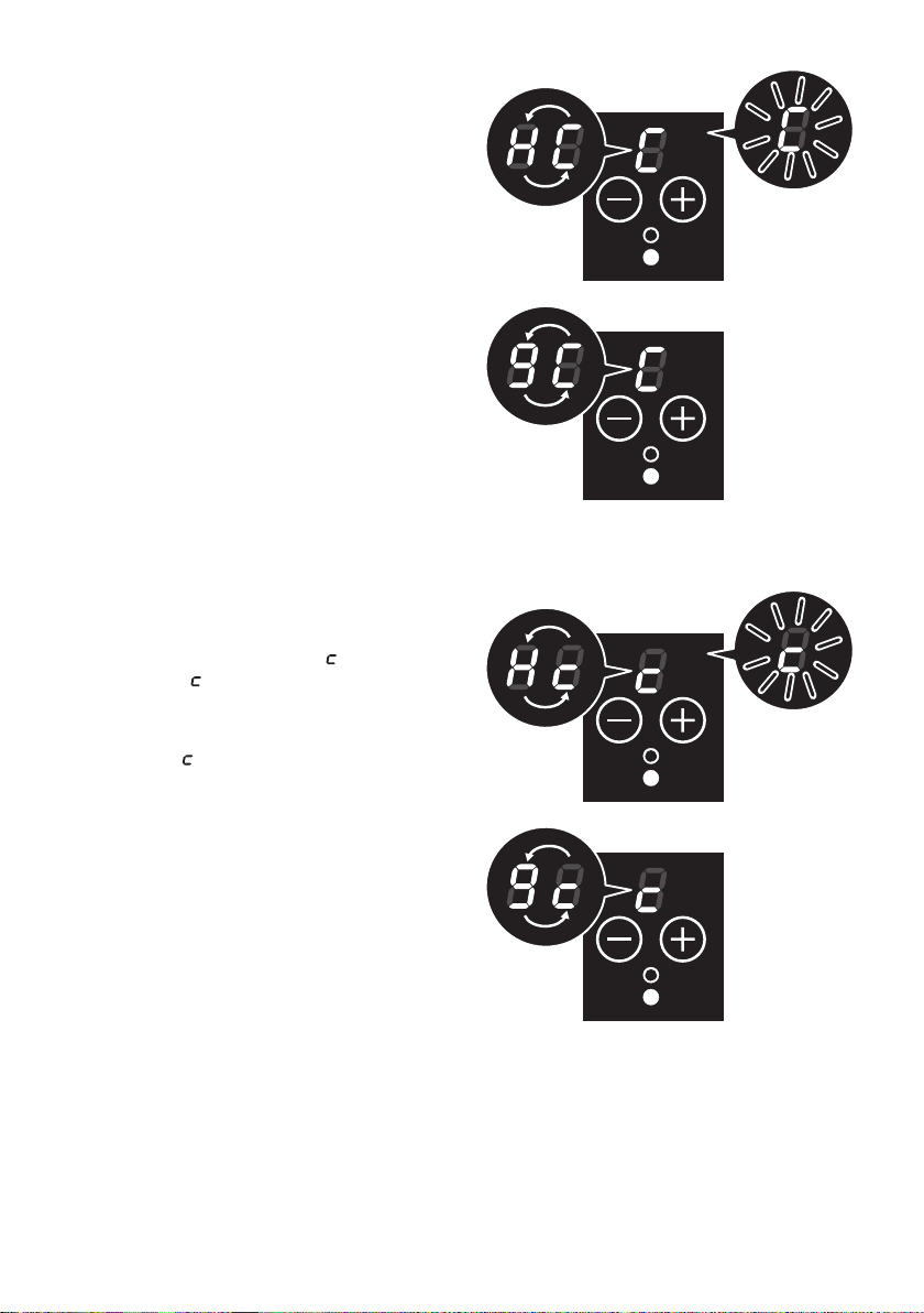
THERMAL PROTECTION
The indu ction cookto p is fitted wit h
safety devices to protect the electronic
system and each cooking zone from
overheating.
OVERHEATING OF COOKING ZONE
– Cooking zone OFF: the cooking zone
display shows “ H ” and “ C” alternating or just “ C ” blinking.
– Cooking zone ON: the cooking zone
display alternates between set power
level and “ C ”.
No power is delivered to the cooking
zone.
L et th e coo kin g zon e coo l dow n
before using.
OVERHEATING OF INDUCTION GENERATOR
– Cooking zone OFF: the cooking zone
display shows “ H ” and “ ” alternating or just “ ” blinking.
– Cooking zone ON: the cooking zone
display alternates between set power
level and “ ”.
No power is delivered to the cooking
zone.
L et th e coo kin g zon e coo l dow n
before using.
7
The ceramic cooktop is fitted with induction cooking zones.
These zones, shown by painted disks on the ceramic surface, are controlled by a touch
control system.
INDUCTION COOKING SYSTEM
When your induction hob is switched on and a cooking zone has been selected, the
electronic circuits produce induced currents that instantaneously heat the bottom of the
pan which then transfers this heat to the food.
Cooking takes place with hardly any energy loss between the induction hob and the food.
Your induction hob operates only if a correct pan with the right features is placed on a
cooking zone. Please refer to "Cookware for Induction Cooking".
COOKWARE FOR INDUCTION COOKING
The induction cooking system OPERATES ONLY if using correct cookware suitable for
induction cooking.
The bottom of the pan has to be ferromagnetic to generate the electromagnetic field necessary for the heating process (meaning a magnet has to stick to the bottom of the pan).
Pans made from the following materials are not suitable:
– glass, wood, porcelain, ceramic, stoneware;
– pure stainless steel, aluminium or copper without magnetic bottom.
To check if a pan is suitable or not:
– Test the bottom of the pan with a magnet: if the magnet sticks, the pan is suitable.
– If a magnet is not available pour a small amount of water inside the pan and place the
pan on a cooking zone. Switch on the cooking zone: if the set power level flashes on
the cooking zone display, the pan is not suitable (then after 1 minute, the power level
automatically returns to “ 0 ”).
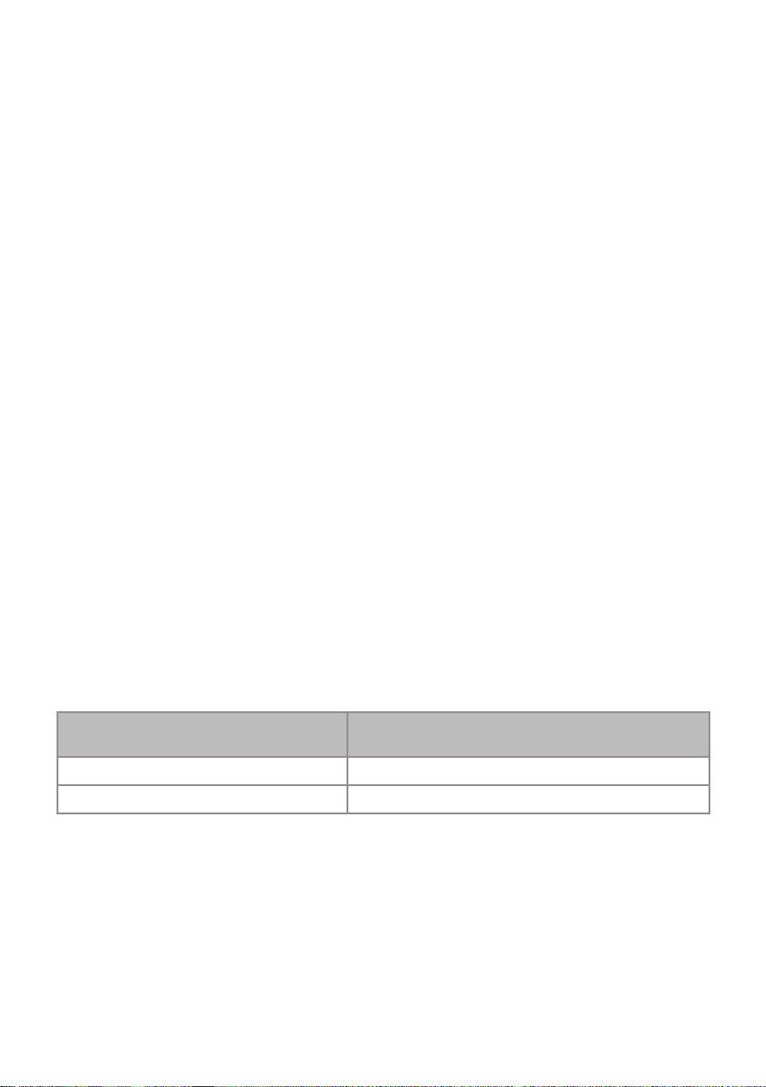
Important note: the cooking zones will not operate if the pan diameter is too small. To
correctly use the cooking zones follow the indications given in the following table.
Induction Cooking Zone
Front zone, Ø 145 mm 80 mm
Rear zone, Ø 210 mm 130 mm
Pay attention: The pan shall always be centred over the middle of the cooking zone. It
is possible to use oversized pans but its bottom shall not touch the other cooking zone.
Always use pans with thick, completely flat bottom.
Do not use pans with concave or convex bottom; these could cause overheating of the
cooking zone.
Note: Some types of pans could cause noise when used on an induction cooking zone.
The noise does not mean any failure on the appliance and does not influence the cooking operation.
8
Minimum Pan Diameter Recommended
(referred to the bottom of the pan)

HOW TO TURN THE TOUCH CONTROL
ON AND OFF
Switching ON
Press the key and keep it pressed
until the touch control is lighted.
The displays of the cooking zones read
“ 0 ”.
Notes:
– If the safety key-lock protection is
active, the touch control can be turned
ON only after having deactivated this
protection.
– Auto switch-off: If a cooking zone is
not turned ON within 10 seconds, the
touch control will automatically switch
off.
Switching OFF
The touch control may be switched OFF
at any time by pressing the key .
If any cooking zones are turned ON, they
will be turned OFF.
9

POWER IGNITION AND ADJUSTMENT
OF A COOKING ZONE
To turn ON a cooking zone the touch
control must be switched ON (see section “How To Turn the Touch Control ON
and OFF”).
Press the key and keep it pressed
until the desired power level, ranging
between 1 and 9 is set.
As an alternative, press the key .
The choice starts from level 9 (maximum level) down to 1 (minimum level).
To reset the power level press the key
and keep it pressed until power level
zero ( 0 ) or alternatively press the keys
and at the same time.
AFTERHEAT IN COOKING ZONE/S
When switching off a cook ing zone
(power level 0 ), if the temperature of the
zone is too warm to be touched the display will show alternately “ H ” and “ 0 ”.
Whenever the touch control is switched
off, the residual heat is shown by a static
“ H ”.
Avoid touching the hob surface over the
cooking area. Please pay special attention to children.
It is still possible to start cooking again;
just set the required power level.
“ H ” is turned OFF when the cooking
zone temperature drops below a preset
temperature.
OR
Cooking
zone
power level
1
2
3
4
5
6
7
8
9
Front zone
Watt power
75 W 100 W
150 W 200 W
300 W 300 W
400 W 500 W
500 W 700 W
600 W 900 W
800 W 1100 W
1000 W 1600 W
1400 W 2200 W
Rear zone
Watt power
10

BOOSTER FUNCTION REAR COOKING
ZONE ONLY
This function allows the cooking zone to
operate at the Booster maximum power
(above the nominal power) for maximum
10 minutes; it could be used, for example, to rapidly heat up large amount of
water.
This function is available for the rear
cooking zone only.
To activate the Booster fu nction, the
touch control must be switched ON (see
section “How to Turn the Touch Control
ON and OFF”).
With the zone at any power level ( 0...9 ),
just touch the key until the rear zone
display shows “ P ”.
At the end of the Booster program (10
minutes) the rear zone is automatically
set to the power level “ 9 ”.
With the zone at the Booster level:
– if touching again the key - a beep
sounds, the heat up program is cancelled and the power level set to “ 9 ”;
– if touching the key - an error beep
sounds but none change is performed;
– if to u ching the k e y - a beep
sounds, the heat up program is cancelled and the power level set to “ 9 ”.
INDUCTION HEATERS POWER
MANAGEMENT
The maximum power of the cooktop is
limited to 3600 W.
This means that the electronic interface
automatically manages the power levels
of the heaters in order to not exceed the
maximum power limit (see also table on
the previous page).
– Both the zones can be used, at the
same time, from power levels “ 1 ” to
“ 9 ”;
– With the front zone set to power level
“7 ”, “ 8 ” or “ 9 ”, if setting the Booster
program on the rear zone the power
level of the front zone is automatically
reduced to “ 6 ".
–
With the Booster program set on the rear
zone, if setting the power level “ 7 ”, “ 8 ”
or “ 9 ” on the front zone the power level
of the rear zone is automatically reduced
to “ 9 ”.
11

SAFETY KEY-LOCK TO PROTECT
CHILDREN
This function locks the touch-control
keys against unwanted activation.
To activate the key-lock press the key
; the indicator light above the key
symbol will light up.
– Cooking zone/s operating (power level
already set) - with the key-lock protection active it is only possible to switch
off the cooktop.
– Cooktop off - with the key-lock protec-
tion active it is not possible to use the
cooktop. To use the cooktop deactivate this protection.
To deactivate the key-lock protection
just press the key ; the indicator light
above the key symbol will go out.
12

PROGRAM FOR AUTOMATIC
SWITCHING OFF OF ONE COOKING
ZONE
This function permits to set a timer from
1 to 99 minutes for automatic turning
OFF of one cooking zone only.
Note: It is not possible to set this pro-
gram for both the cooking zones.
With the touch control switched ON:
– Press the timer keys or ; a beep
sounds and the timer display shows
“ 00 ”. The displays of the cooking
zones show " " (timer).
– Within 10 seconds, select the cooking
zone to be programmed by using the
cooking zone keys or ; a beep
sounds and the led next to the heater
display start blinking.
– Set the disired power level by using
the cooking zone keys or ; the
led next to the heater display is stably
lit (not blinking).
– Wi thin 10 sec o nds, s e t the t i mer
by using the timer keys or to
increase or reduce the value (when
touching the keys, the led next to the
heater display is blinking). If the selected time is “ 00 ”, the timer is switched
off automatically after 10 seconds.
– The countdown starts 10 seco nds
after the last selection. The time can
be changed at any time by using the
timer keys; the countdown stops and
then the timer changes the stop time.
OR
OR
Now the program for automatic switching off is complete.
At the end of the countdown the cooking zone will switch off automatically,
an acoustic signal (beep) will sound (for
one minute only), “ 00 ” will flash on
the timer display and the led next to the
heater display will blink.
Press any button of the touch control to
reset the timer.
Note: The program for automatic switch
off can be cancelled at any time by
resetting the timer to “ 00 ”).
OR
13

OPERATION TIME LIMIT OF COOKING
ZONES
Each cooking zone is automatical ly
switched OFF after a maximum preset
time if no operation is performed.
The maximum preset time limit depends
on the set power level, as illustrated in
this schedule.
Each operation on the cooking hob by
using the keys , will reset the maximum operation time at its initial value.
Cooking zone
power level
1
2
3
4
Operation
time limit
10 hours
5 hours
5 hours
4 hours
5
6
7
8
9
P
Booster
(rear zone only)
3 hours
2 hours
2 hours
2 hours
1 hour
10 minutes
14
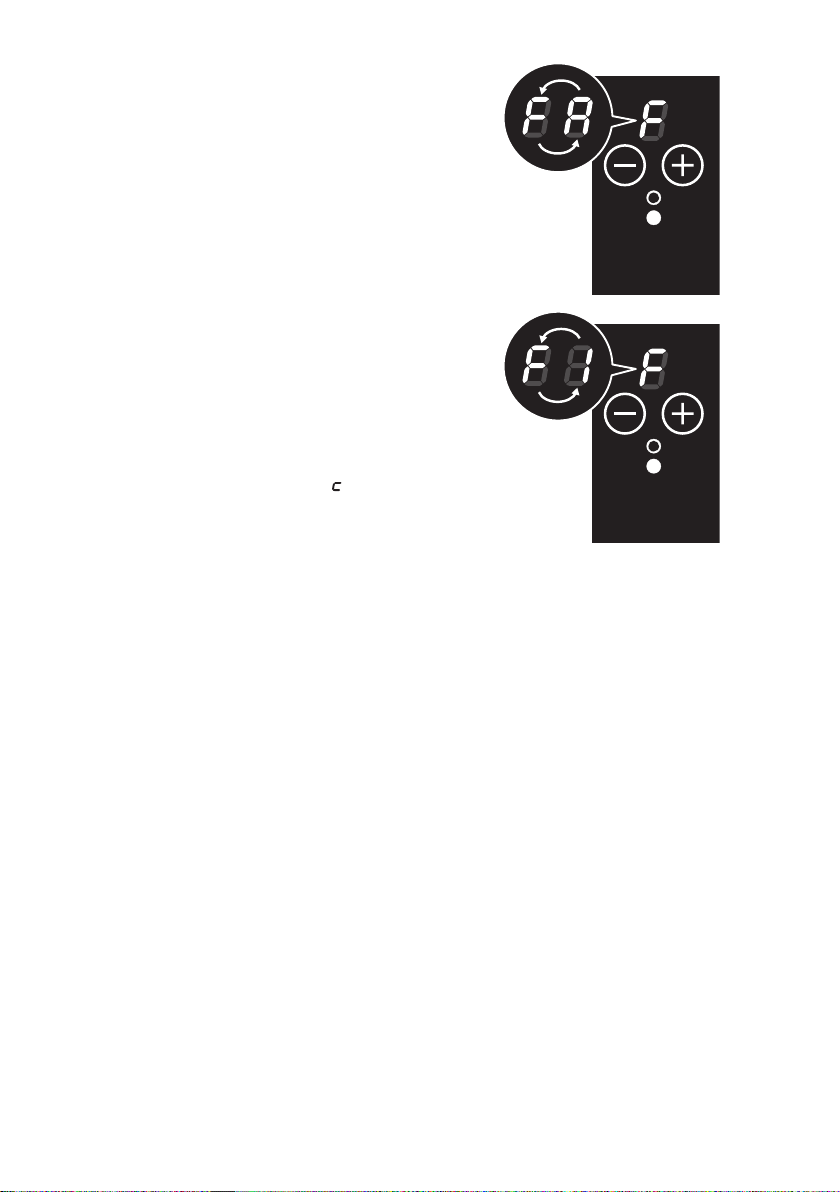
ERROR CODE ON THE DISPLAY/S
If an erro r messa ge appe ars on the
display/s (the display/s show/s “ F ” and
another character alternating - e.g. “ F ”
and “ A ”, “ F ” and “ 0 ”, .....) :
1. Disco nnect the cooktop from the
mains.
2. Reconnect the cooktop and turn it on.
3. Wait for about two minutes and if the
problem does not appear the cooktop
can be used.
4. If the problem does not disappear
repeat step from 1 to 3.
5. If the problem continues, disconnect
the cooktop from the mains and contact your Authorised Service Centre.
Important: In the case of error message
“ F ” and “ L ” or “ F ” and “ ” see
notes at page 6.
DISPLAY/S OFF OR NOT CORRECTLY
OPERATING
If a display or the displays are only
partially lit or not lit.
1. Switch off the cooktop and disconnect it from the mains.
2. Reconnect the cooktop and turn it on.
3. Wait for about two minutes and if the
problem does not appear the cooktop
can be used.
4. If the problem does not disappear
repeat step from 1 to 3.
5. If the problem continues, disconnect
the cooktop from the mains and contact your Authorised Service Centre.
15

3
•
If any of these products has melted on the ceramic surface, you should remove it
immediately (when the surface is still hot) by using a scraper to avoid any permanent
damage to the surface of the hob (available under part no. 103138).
CLEANING AND MAINTENANCE
CLEANING THE CERAMIC HOB
Before you begin cleaning make sure that the hob is switched off.
• Remove spillages and other types of incrustations.
• Dust or food particles can be removed with a damp cloth.
• If you use a detergent, please make sure that it is not abrasive or scouring. Abrasive
or scouring powders can damage the glass surface of the hob.
• All traces of the cleaner must be removed with a damp cloth.
• Dust, fat and liquids from food that has boiled over must be removed as soon as possible.
• If they are allowed to harden they become increasingly difficult to remove.
This is especially true in the case of sugar/syrup mixtures which could perma-
nently pit the surface of the hob if left to burn on it.
• I
•
Do not put articles on the hob which can melt: i.e plastic, aluminium foil, sugar, sugar
syrup mixtures etc.
• Avoid using a knife or other sharp utensil as these may damage the ceramic surface.
• Do not use steel wool or an abrasive sponge which could scratch the surface
nently
.
Do not use cleaning products with a chlorine or acidic base.
perma-
SIDE STAINLESS STEEL TRIMS
• Stainless steel parts must be rinsed with water and dried with a soft and clean cloth.
• For persistent dirt, use specific non-abrasive products available commercially or a little hot vinegar.
Do not use harsh abrasive cleaners
or sharp metal scrapers to clean the
glass since they can scratch the
ace, which may result in
surf
shattering of the glass.
Do not use a steam cleaner because
the moisture can get into the appliance thus make it unsafe.
16
-
Fig. 3.1

ADVICE FOR THE
INSTALLER
17

4
INSTALLATION
CAUTION:
• This appliance shall only be serviced by authorized personnel.
• This appliance is to be installed only by an authorised person according to the current local regulations and in observation of the manufacturer’s instructions.
• Incorrect installation, for which the manufacturer accepts no responsibility, may
cause personal injury of damage.
• Always disconnect the cooktop from mains power supply before carrying out any
maintenance operations or repairs.
WARNING !
• We would point out that the adhesive which bonds the plastic laminate to the furniture
must withstand temperatures not less than 150 °C to avoid delamination.
• The appliance must be housed in heat resistant units.
• The walls of the units must be capable of resisting temperatures of 75 °C above room
temperature.
18
Fig. 4.1
A
510
275
300
490
(1)
50
from the top of
50 mm
A
68 mm
(1): at least 50 mm between the back side
of the cut-out and the back of the
countertop.
countertop to bottom
metal cover
from the top of
countertop to
terminal block

This cooktop can be built into a working
surface 30 to 40 mm thick and 600 mm
deep.
In order to install the ceramic hob into
the kit che n fixture , a hole with th e
dimensions shown in figure 4.1 has to
be made, keeping in consideration the
following:
• The cooktop shall not be installed
directly above a dishwasher, fridge,
freezer, washing machine or clothes
dryer, as the humidity may damage
the cooktop electronics.
• If the cooktop is installed above an
oven, the oven shall be provided with
cooling fan. The two appliances should
be connected to the electrical supply
with independent connections.
–
I M P O R TA N T W AR N I N G ! T h i s
cooktop requires adequate supply
of fresh, cool air to fully function.
The base of the cooktop must have
direct unrestricted ventilation to the
room where the cooktop is installed.
Follow the requirements of figure 4.3.
• The ceramic hob must be kept no less
than 60 mm away from any side wall.
450 mm
60 mm minimum between the side
of the cut-out and the side wall
Fig. 4.2
650 mm
500 mm
• The rear wall must be at least 50 mm from the ceramic hob.
• There must be a distance of at least 650 mm between the hob and any wall cupboard
or extractor hood positioned immediately above (see fig. 4.2).
• The coatings of the walls of the unit or appliances near the cooktop must be heat
resistant.
• Do not install the appliance near inflammable materials (eg. curtains).
7 mm 7 mm
Fig. 4.3
70 mm
Minimum clearances and
ventilation requirements
(cupboard or drawer space below)
Oven with
cooling fan
min 30 mm min 30 mm
Minimum clearances and
ventilation requirements
(oven installed below)
19

FASTENING THE COOKTOP
Each cooktop is supplied with a set of tabs and screws to fasten it on units with a working surface from 3 to 4 cm deep.
The kit includes 4 tabs A and 4 self-threading screws B (fig. 4.4).
• Cut the unit.
• Turn the hob upside down and rest the glass side on a cloth.
• Spread the seal C around the edge of the hob (fig. 4.5).
• Put tabs A into the mountings; only tighten screws B a few turns.
Make sure that the tabs are mounted correctly as shown in the figure 4.4.
• Put the cooktop into the hole cut into the unit and position it correctly.
• Put tabs A into place, tooth D of the tabs should go into the hole.
• Tighten screws B until the cooktop is completely secured.
• Using a sharp tool cut off the part of gasket C which protrudes from the cooktop. Take
care not to damage the workbench.
C
D
20
A
B
30 mm min.
Fig. 4.4
40 mm max.
A
C
C
Adhesive side
A
Fig. 4.5

5
Replacing the power cord must be done by a qualified electrician in
accordance with the instructions supplied by the manufacturer and in
compliance with established electrical regulations.
IMPORTANT: Installation must be carried out according to the manufacturer’s
instructions. Incorrect installation may cause harm and damage to people, animals or property, for which the manufacturer accepts no responsibility.
Before carrying out any work on the electrical section of the appliance, it must
be disconnected from the mains.
Connection to a good earth wiring system is absolutely essential.
The manufacturer accepts no responsibility for any inconvenience caused by failure to comply with this rule.
ELECTRICAL CONNECTION
ELECTRICAL REQUIREMENTS
• Connection to the electric power supply must be carried out by a qualified technician
and following the appropriate safety regulations.
• The appliance must be connected to the mains checking that the voltage corresponds
to the value given in the rating plate and that the electrical cable sections can withstand the load specified on the plate.
• If the hob is supplied without plug, fit a standard plug which is suitable for the power
absorbed by the appliance and in conformity with the local rules in force.
• The plug must be put into a socket connected to the earth system in compliance with
safety rules.
A suitable isolating switch providing full disconnectio n from the mains power supply
•
(under overvoltage category III conditions) shall be incorporated in the permanent
wiring, mounted and positioned to comply with the local wiring rules and regulatio ns.
The isolating switch must be of an approved type and provide a 3 mm air gap contact
separation in all poles (or in all active [phase] conductors if the local wiring rules
allow for this variation of the requirements).
• The power supply cable must not touch the hot parts and must be positioned so that it
does not exceed 50°C above ambient.
• Once the appliance has been installed, the power switch or power plug must always
be in a accessible position.
N.B. For connections to the mains power supply, never use adaptors, reductions or
multiple power points as these may overheat and catch fire.
In the event that installation should require modifications to the mains supply wiring system, it is recommended that a qualified technician be called to carry out substitution.
The technician will also have to verify that the cross-section of the electric cables on the
power point match the appliance’s power rating.
If the hob surface is cracked disconnect the appliance from the mains and contact
the After-Sales Service.
21

CONNECTING OF THE POWER SUPPLY CABLE
2 0-240 V
E
N
L
• Unhook the terminal board cover by inserting a screwdriver into the two hooks A (fig.
5.1).
• Open the cable gland by unscrewing screw F (fig. 5.3), unscrew the terminal screws
and remove the cable.
• The new supply cable, of suitable type and section, is connected to the terminal board
following the diagram of fig. 5.2.
FEEDER CABLE SECTION “Type H05RR-F”
2 0-240 V ~ 3 x 1.5 mm
3
WARNING: If the power supply cable
is damaged, it must be replaced only
by an authorised service agent in
order to avoid a hazard.
2
3600 W MAX (15.6 A)
3
E Earth
N Neutral
L Live
Fig. 5.2
Fig. 5.1
22
A
Fig. 5.3
F

Descriptions and illustrations in this booklet are given as simply indicative. The manufacturer reserves
the right, considering the characteristics of the models described here, at any time and without notice,
to make eventual necessary modifications for their construction or for commercial needs.
23

cod. 1103762 - ß1
 Loading...