


OWNER’S MANUAL
PowerTap SL2.4

Copyright
Copyright 2005. All rights reserved. No part of this publication may be copied, photographed, reproduced, translated, transmitted electronically or placed on digital media without the prior written consent of Saris Cycling Group, Inc.
Trademarks
Saris Cycling Group, Inc , PowerTap and the PowerTap logo, are all registered trademarks of Saris Cycling Group, Inc. All other product, brand, or trade names used in this manual may be trademarks or registered trademarks of their respective owners.
Modifications
Saris Cycling Group, Inc reserves the right to make improvements and/or updates to the products described herein at any time without notice.
FCC Statement of Compliance:
Statement of Compliance for FCC and Industry Canada:
Saris Cycling Group, Inc. Model #: PowerTap SL2.4 IC: 6459A-SL2P401
FCC ID: T8P-SL2P401
"This device complies with Industry Canada and Part 15 of the FCC Rules. Operation is subject to the following two conditions: (1) This device may not cause harmful interference, and (2) this device must accept any interference received, including interference that may cause undesired operation."
The term "IC:" before the radio certification number only signifies that Industry Canada technical specifications were met.
Changes or modifications to this device not expressly approved by the party responsible for compliance with FCC regulations (the manufacturer) could void the user's authority to operate the equipment.
This equipment has been tested and found to comply with the limits for a Class B digital device, pursuant to part 15 of the FCC Rules. These limits are designed to provide reasonable protection against harmful interference in a normal installation. This equipment generates, uses and can radiate radio frequency energy and, if not installed and used in accordance with the instructions, may cause harmful interference to radio communications. However, there is no guarantee that interference will not occur in a particular installation
About This Manual
Thank you for your purchase of the CycleOps PowerTap SL2.4. PowerTap technology is the ultimate measure of performance by providing real-time feedback on your training intensity. No other equipment will give you greater performance return on your investment.
This manual describes the proper use and maintenance of the PowerTap SL2.4. Every person, independent of skill level, should read at least PRECAUSTION: IMPORTANT prior to use of the PowerTap.
DEFINITIONS
Bold Letters - Bring special attention to important points and that should be read and understood prior to using the PowerTap.
Italicized Letters - Indicate reference to another section of the manual where further explanations are found.
This manual describes the functions of the PowerTap SL2.4 and the information provided may not apply to all PowerTap models. For the most current owners manual available please consult www.cycleops.com.
3
Table of Contents
About this Manual |
|
|
|
|
|
Precautions: Important..... |
5 |
|
|
|
|
System Overview..... |
7 |
|
|
|
|
The PowerTap System.....7 |
|||||
Preparing for Installation..... |
7 |
||||
Compatibility..... |
8 |
|
|
||
Wheel Building..... |
8 |
|
|
||
System Installation..... |
9 |
|
|||
General Computer Operation..... |
12 |
|
|||
Display Levels..... |
12 |
|
|
||
Display Modes..... |
12 |
|
|
||
|
Finding Sensors |
||||
|
Clearing Data |
|
|||
Buttons..... |
12 |
|
|
|
|
Power Conservation..... |
13 |
|
|||
Computer Navigation..... |
14 |
|
|
|
|
Power Function..... |
14 |
|
|
||
Torque Function.....15 |
|
||||
|
Zero Torque..... |
15 |
|||
Speed Function..... |
16 |
|
|
||
Multi-Function..... |
17 |
|
|
||
|
Cycle Computer Mode.....18 |
||||
|
Heart Rate Monitor Mode.....20 |
||||
Interval Mode..... |
21 |
|
|
||
Interval Memory Mode..... |
22 |
||||
Computer Setup..... |
23 |
|
|
|
Computer Setup Main Menu.....23 |
||||
Computer Setup 1..... |
24 |
|
||
Computer Setup 2..... |
27 |
|
||
Computer Setup 3..... |
28 |
|
||
Computer Setup 4..... |
29 |
|
||
Computer Setup 5..... |
|
|
||
Maintenance & Specifications..... |
31 |
|
||
Bearings..... |
31 |
|
|
|
Freehub..... |
31 |
|
|
|
Freehub Replacement..... |
31 |
|||
Computer Batteries..... |
33 |
|
||
Technical Specifications..... |
33 |
|||
Range of Measurement..... |
33 |
|||
Hub Batteries.....34 |
|
|
||
Battery Replacement.....34 |
||||
Test Mode..... |
35 |
|
|
|
Trouble Shooting..... |
37 |
|
|
|
Glossary.....39 |
|
|
|
|
4
Precautions: Important
•Before beginning any exercise program, consult your physician.
•Keep your eyes on the road. Do not become overly engaged with the PowerTap display. We recommend familiarizing yourself with computer functions while stationary.
•The computer, receiver, and hub are water resistant, not water proof. Avoid sustained water contact and do not deliberately place the PowerTap or its components in water or under highpressure sprays. Therefore caution should be used when riding in rain. Following such rides, special precautions should be taken including removing the PowerTap plastic twist cap and allowing the hub to air dry.
•Wash off dirt with a cloth soaked in a weak mixture of neutral detergent and water and wipe excess water off with a dry cloth Avoid spraying the unit directly with solvent mixture. Do not use thinner or other solvents to clean parts as they may dissolve the plastic console casings.
•If you are not familiar with bike maintenance please contact a professional bicycle mechanic before servicing. The power measuring components of the PowerTap are highly complex and should only be serviced by Saris Cycling Group.
•The plastic cover on the hub should be removed only when replacing batteries or when allowing the unit to dry after submersion in water. Repeated disassembly may compromise the effectiveness of the O-ring seals. O-rings should be inspected and replaced if necessary when ever the battery cover is removed. Use a light coating of grease when reinstalling the battery cap on the O-rings.
•During the course of repair do not remove the torque tube. There are no serviceable parts inside. Special tools are required for reassembly and calibration. If problems are suspected contact Saris Cycling Group directly at 800-783-7257 (001 608 274 6550).
5
Precautions: Important, cont.
•The PowerTap wheel does not include a quick release skewer. CycleOps recommends using a steel skewer.
•Both sides of the PowerTap should be built using a 3x spoke lacing pattern. Because of the design of the PowerTap, torque is transmitted through the hub to the non-drive side. For additional questions please consult WHEEL BUILDING.
•Failure to adhere to these precautions may cause premature failure or incorrect operation of the unit and may void the warranty. Please register your PowerTap at www.cycleops.com.
6

System Overview
THE POWER TAP SYSTEM
The PowerTap system includes a power-measuring hub which measures torque and wheel speed. This information is transmitted to a computer mounted on the handlebar or stem. Heart rate data is transferred via A coded telemetry signal from the chest strap monitor. The data is then integrated to display current, average, and maximum biometric information.
PREPARING FOR INSTALLATION
The PowerTap SL2.4 hub comes either alone or in a pre-built wheel. If purchased alone, the hub must be built into a complete wheel prior to use. Other items necessary for installation and not provided include a cassette, spoke protector, reflectors, skewer, rim strip, tire, and tube (clincher rim) or glue and tubular tire (tubular rim). See TABLE 1 to verify package contents.
TABLE 1
|
Package Contents |
Qty |
Item |
1 |
PowerTap hub (or built wheel) |
1 |
PowerTap computer |
1 |
Chest strap |
4 |
Foam mounting tapes |
12 |
Cable ties |
1 |
Training With Power guide |
1 |
PowerTuned Agent CD |
1 |
Link USB Cable |
1 |
Extra CPU Battery |
7

System Overview cont.
COMPATABILITY
The PowerTap SL2.4 hub is compatible with Shimano 8, 9, and 10 speed systems or Campagnolo 8, 9, and 10 speed systems. Freehub bodies may be interchanged. Reference FREEHUB REPLACEMENT for further instructions.
The PowerTap is available in 130mm and 135mm axle lengths. Only insert the correctly spaced PowerTap hub into your frame. For example, only use a 130mm-spaced hub in a 130mm road frame. Do not force the hub into any frame. Doing so may cause failure of the frame, hub, or both, and will void the warranty. Contact your dealer or Saris Cycling Group to address any special compatibility concerns.
WHEEL BUILDING
Contact a wheel building professional or dealer for assistance in building the PowerTap SL2.4 wheel if not purchased as a complete wheel. Both sides of the PowerTap should be built using only a 3x spoke lacing pattern. Due to the design of the hub, the load pattern is not the same as a conventional hub. Slotting the hub flanges to accommodate bladed spokes is not recommended and will void the warranty. Complete wheel building hub dimensions are listed in TABLE 2.
Reference a spoke-length calculator to determine proper spoke length.
TABLE 2 - Wheel Building Dimensions
|
|
Measurements |
|
|
Drive |
|
|
Non-Drive |
|
|
|
|
|
|
|
|
|
|
|||
|
|
Hub Center To |
|
|
17.4mm |
|
|
31.7mm |
|
|
|
|
Flange |
|
|
|
|
|
|
||
|
|
Flange Diameter |
|
|
70mm |
|
|
70mm |
|
|
Spoke Hole Diameter: 2.5
8
System Overview cont.
SYSTEM INSTALLATION
1. Insert Wheel Into Frame
Insert the PowerTap SL2.4 wheel into the frame. Make sure the axel is correctly positioned in the dropouts and secure the wheel in place with a steel skewer.
2. Attach Computer Shoe to Handlebar or Stem
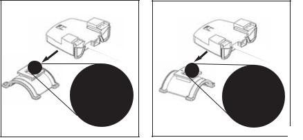
The shoe can be mounted on either the handlebar or stem. Secure the receiver shoe with cable ties. Slide the receiver shoe in the direction of the arrow as depicted in either FIGURE 2A or 2B depending on mounting location.
2A. Attach Receiver mount to Handlebar
Slide shoe in direction of arrow onto the base.
Receiver Shoe
2B. Attach Receiver mount to Stem
Slide shoe in direction of arrow onto the base.
Receiver Shoe
|
Arrow |
|
Arrow |
Mounting Base |
Mounting Base |
|
9
3. Place Computer into Shoe
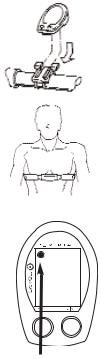
Place the computer into the mounting shoe on the handlebar or stem. Line up the slots on the base of the computer with the bracket and slide computer toward the rider (FIGURE 5). NOTE: Ensure the computer is fully inserted onto the receiver shoe for proper data transmission.
4 Heart Rate Monitor Strap |
|
|
Position the heart rate monitor strap on your torso as pictured in FIG- |
FIGURE 6 |
|
URE 6. The strap should rest just beneath the pectoralis muscles of |
||
|
||
the chest. For best results slightly moisten the electrodes where con- |
|
|
tact is made with skin. The heart rate strap must be worn to enable |
|
|
the heart rate function. NOTE: The chest strap for the PowerTap SL2.4 |
|
|
uses a coded frequency and is not compatible with other manufactur- |
|
|
er’s chest straps. |
|
|
|
|
|
5. Verify Installation |
FIGURE 7 |
|
Check to make sure all components are properly secured. Spin the |
|
|
rear wheel and verify that in the upper left hand corner of the com- |
|
|
puter the transmission icon illuminates (FIGURE 7). This indicates |
|
|
the hub is properly transmitting a signal to the receiver and com- |
|
|
puter. If the transmission icon is not illuminated consult Finding |
|
|
Section Sensors for further instructions. |
|
10
General Computer Operation
DISPLAY LEVELS |
|
|
|
|
|||
The computer has three (3) main display levels: |
TRANS. |
||||||
|
|
|
|
|
|
|
ICON |
Top |
|
|
|
|
|
Power |
|
|
|
|
|
||||
Middle |
|
|
|
|
Speed |
INTERVAL |
|
|
|
|
|||||
Bottom |
|
|
|
Multi-Function |
|||
|
|
|
DISPLAY |
||||
|
|
|
|||||
NOTE: These locations only apply to trip and
interval modes and does not apply to Cycle Computer or Heart Rate Monitor Function. See COMPUTER SETUP 4 to customize display options.
DISPLAY MODES
The computer has two (2) main modes of operation:
1)Trip
2)Interval
Hold [MODE] to toggle between display modes.
BUTTONS
There are two (2) buttons on the computer:
1)[Mode]
2)[Select]
MODE (LEFT) Changes active mode
NOTE: [BRACKETED] words indicate buttons.
There are five (5) types of button presses:
POWER 365 DISPLAY
WATTS3
25 2.4 SPEED MI DISPLAY
58.I0 |
MULTI |
|
DISPLAY |
BOTH |
SELECT (RIGHT) |
Clear data |
Select function |
Enter setup |
|
1) Press [MODE] or [SELECT] - a single press and release of either [MODE] or [SELECT]. Used for entering different modes and functionality.
11

2)Hold [MODE] or [SELECT] - a single button press and hold of either [MODE] or [SELECT] for 2 sec. Used for initiating a new Interval.
3)Press [MODE] and [SELECT] - simultaneously press and release of both [MODE] and [SELECT].
4)Hold [MODE] and [SELECT] - simultaneously press and hold both [MODE] and [SELECT] for 2 sec. NOTE: Continuing to hold longer than 2 sec. and releasing will clear all data.
5)Extended Hold [MODE] and [SELECT] - simultaneously press and hold of both [MODE] and [SELECT] for greater than 5 sec. Used for initiating scrolling menu.
SCROLLING MENU:
SCROLLING MENU:
Find: If [MODE] and [SELECT] are released
When “Find” is displayed the computer will find
Search for the PowerTap hub.
clr: If [MODE] and [SELECT] are released when
clr is displayed ALL DATA WILL BE ERASED .
SEt: If [MODE] and [SELECT] are released
When SEt is displayed on the top level of the
Screen, a flashing “E”, d and t on the middle
Level and 12345 on the bottom level.
E = exit, return to ride mode d = restore default settings T = test mode
1 2 3 4 = setup menus
POWER CONSERVATION
The computer and hub have power saving features to prolong battery life. The computer powers down the display after four (4) minutes of inactivity. Press either [MODE] or [SELECT] to activate the display. Similarly, the hub powers down after five (5) minutes of inactivity. The transmission icon will not be visible when the hub is asleep. To wake the hub spin the wheel and verify the transmission icon is illuminated.
12

Computer Navigation
POWER FUNCTION
The top level of the main display shows current, max, and average power readings. |
|
|
|
|
1) Press [MODE] to scroll the cursor to the top line of the main display |
|
|
|
|
2) Press [SELECT] to toggle through the power function options. |
|
|
|
|
For accurate power readings it is important to frequently zero the torque, see ZERO TORQUE. |
|
|||
Current Power |
|
FIGURE 9 |
|
|
|
|
365WATTS |
||
Power is displayed in watts from 0-1999 in 1 watt increments. Current power |
|
|
||
readings are displayed only when the word “WATTS” appears below the top line |
|
|
25 |
3 |
(FIGURE 9). NOTE: If “WATTS” does not appear under the top line the computer is |
|
|
|
|
in the Cycle Computer Function. To return to power readings see CYCLE |
|
|
MI |
|
|
|
58.I0 |
||
COMPUTER MODE. |
|
D |
||
Maximum Power |
|
FIGURE 10 |
|
|
|
|
849WATTS |
||
Both “WATTS” and “MX” displayed simultaneously indicate the highest recorded |
|
MX |
||
|
|
|
|
|
power output since the last time the data was cleared in trip mode or the selected |
|
|
25 3 |
|
interval in interval mode. (FIGURE 10) |
|
|
||
|
|
|
MI |
|
Average Power |
|
D |
58.I0 |
|
|
FIGURE 11 |
|
||
Both “WATTS” and “AVG” displayed simultaneously indicate the average power |
|
|
||
output since the last time the data was cleared in trip mode or the selected |
|
|
I95 |
|
|
|
|
|
|
interval in interval mode. (FIGURE 11) |
|
|
AV WATTS |
|
|
|
|
25 3 |
|
|
|
|
|
MI |
|
|
D |
58.I0 |
|
13
 Loading...