


INSTRUCTION MANUAL
Before using the TV, please read this manual thoroughly, and retain it for future reference.
Model:LCDVD322A

English
CONTENTS
1SAFETYPRECAUTION
IMPORTANT
2SAFETY INSTRUCTION
3ACCESSORIES
4GETTINGSTARTED
CONTROL
5REFERENCE GUIDE
6CONNECTIONS
7WALLMOUNT INSTALLATION
8INITIALSETUP
9TVSETUP
|
1 |
|
|
|
|
|
2 |
|
|
|
|
|
3 |
|
|
|
|
|
3 |
|
|
|
|
Remote Control |
4 |
Front Frame |
6 |
Back Frame |
6 |
Side Panel |
7 |
|
|
|
|
Antenna Connection |
8 |
AV Connection |
8 |
Y Pb Pr Connection |
9 |
HDMI Connection |
9 |
VGA Connection |
10 |
Power Cord Connection |
10 |
Coax(SPDIF) Connection |
11 |
|
|
|
|
|
12 |
|
|
|
|
Putting The Unit On A Proper Place |
13 |
Turning The Unit On For The First Time |
13 |
Source Selection |
13 |
|
|
|
|
Picture Menu |
15 |
Audio Menu |
17 |
Time Menu |
19 |
Setup Menu |
20 |
LOCK(Parental) Menu |
23 |
TV(CHANNEL) Menu |
26 |
Zoom Function (For DVD) |
27 |

CONTENTS
10DISCFORMATS
11CD / DVD
OPERATION
CUSTOMIZING
12THE DVD FUNCTION SETTINGS
13MAINTENANCE
14DISPLAYMODE
15SPECIFICATION
TROUBLE-
16SHOOTING GUIDE
|
28 |
|
|
|
|
Basic Operations |
29 |
Special Functions |
32 |
Mp3 / JPEG Playback |
34 |
|
|
|
|
DVD Menu |
35 |
|
|
37 |
|
|
|
|
|
|
|
|
|
|
PC Formats |
38 |
|
|
Video Formats |
38 |
|
|
|
|
|
|
|
|
|
|
|
40 |
|
|
|
|
|
|
|
|
|
|
DVD Symptom |
41 |
|
|
TV Symptom |
42 |
|
SAFETY CLASS :This is an IEC safety class I product and it must be grounded for safety.

SAFETYPRECAUTION
*CAUTION MARKING WAS LOCATED AT BOTTOM PLACEMENTINFORMATION ENCLOSURE OF THE APPARATUS.
• Do not use this unit in places that are extremely hot, cold, dusty or humid.
• Do not restrict the airflow of this unit by placing it somewhere with poor airflow, by covering it with a cloth, by placing it on bedding or carpeting.


 SAFETYINFORMATION
WARNING:TO REDUCE THE RISK OF ELECTRIC SHOCK DO NOT REMOVE COVER OR BACK NO USER SERVICEABLE PARTS INSIDE.
REFER SERVICING TO QUALIFIED SERVICE PERSONNEL.
•When connecting or disconnecting the AC power cord, grip the plug and not the cord itself. Pulling the cord may damage it and create a hazard.
•When youare not going to use the unit for a long period of time, disconnect the AC power cord.
The lightning flash with arrowhead symbol, within an equilateral triangle,is intended to alert the user to the presence of uninsulated dangerous voltage”within the product's enclosure
that may beof sufficient magnitude to constitute a risk of electric shock to persons.
The exclamation point within an equilateral Triangle is intended to alert the user to The presence of important operating and
maintenance (servicing) instructions in the literature accompanying the appliance.
CAUTION
INVISIBLE LASER RADIATION WHEN |
This product |
|
Contains a low |
||
OPEN AND INTERLOCKS DEFEATED |
||
power laser device. |
||
AVOID EXPOSURE TO BEAM |
||
|
CLASS 1 LASER
PRODUCT
CAUTION
•DANGER OF EXPLOSION IF BATTERY IS INCORRECTLY REPLACED. REPLACE ONLY
WITH THE SAME OR EQUIVALENT TYPE.
•USE OF CONTROLS OR ADJUSTMENTS OR PERFORMANCE OF PROCEDURES OTHER THAN THOSE SPECIFIED MAY RESULT IN HAZARDOUS RADIATION EXPOSURE.
WARNING:
•TO REDUCE THE RISK OF FIRE OR ELECTRIC SHOCK, DO NOT EXPOSE THIS APPLIANCE TO RAIN OR MOISTURE.
TO REVENT FIRE OR SHOCK HAZARD, DO NOT
•EXPOSE THIS UNIT TO RAIN OR MOISTURE. DO NOT PLACE OBJECTS FILLED WITH LIQUIDS ON OR NEAR THIS UNIT.
•SHOULD ANY TROUBLE OCCUR, DISCONNECT THE AC POWER CORD AND REFER SERVICING TO A QUALIFIED TECHNICIAN.
CONDENSATION INFORMATION
•When left in a heated room where it is warm and damp, water droplets or condensation may form inside the equipment. When there is condensation inside the unit, the unit may not function normally. Let the unit stand for 1-2 hours before turning the power on or gradually heat the room and let the unit dry before use.
RATING PLATE LOCATION
The rating plate is located on the rear of the unit.
FCC STATEMENTS
NOTE: This unit has been tested and found to comply with the limits for a Class B digital device, pursuant to Part 15 of the FCC Rules. These limits are designed to provide reasonable protection against harmful interference in a residential installation.
This unit generates, uses and can radiate radio frequency energy and, if not installed and used in accordance with the instructions, may cause harmful interference to radio communication. However, there is no guarantee that interference will not occur in a particular installation. If this unit does cause harmful interference to radio or television reception, which can be determined by turning the unit off and on, the user is encouraged to try to correct the interference by one or more of the following measures:
-Reorient or relocate the receiving antenna.
-Increase the separation between the unit and receiver.
-Connect the unit into an outlet on a circuit different from that to which the receiver is connected.
-Consult the dealer or an experienced radio/TV technician for help.
WARNING:
Changes or modifications to this
unit not expressly approved by the party responsible for compliance could void the user authority
to operate the unit.
1

IMPORTANTSAFETYINSTRUCTIONS
1)Read these instructions. 2)Keep these instructions. 3)Heed all warnings.
4)Follow all instructions.
5)Do not use this apparatus near water. 6)Clean only with a dry cloth.
7)Do not block any ventilation openings. Install in accordance with the manufacturer's instructions.
8)Do not install near any heat sources such as radiators, heat registers, stoves, or other apparatus (Including amplifiers) that produce heat.
9)Do not defect the safety purpose of the polarized or grounding-type plug.
A polarized plug has two blades with one wider than the other.
A groundingtype plug has two blades and a third grounding prong.
The wide blade or the third prong is provided for your safety.
If the provided plug does not fit into your wall outlet, consult an electrician for replacement of the obsolete outlet. 10)Protect the power cord from being walked on
or pinched particularly at plugs, convenience receptacles, and the point where they exit from the apparatus.
11)Only use attachments / accessories specified by the manufacturer.
12)Use only with the cart, stand,
tripod, bracket, or table specified by the manufacturer,
or sold with the apparatus.  When a cart is used, use caution when
  moving the cart / apparatus combination to avoid injury from tip-over.
13)Unplug this apparatus during lightning Storms or when unused for long periods of time.
14)Refer all servicing to qualified service personnel. Servicing is required when the apparatushas been damaged in any way, such as the power cord or plug is damaged, liquid has been spilled or objects have fallen into the apparatus, the apparatus has been exposed to rain or moisture, does not operate normally, or has been dropped.
15)To prevent electric shock, ensure the grounding pin on the AC cord power plug is securely connected.
2
ACCESSORIES |
|
Pleasecheckandidentifythesuppliedaccessories. |
|
Remote control .................................................................................................................. |
x 1 |
Battery(AA) ............................................................................................................ ......... |
x 2 |
Warranty Card ................................................................................................................ |
x 1 |
Instruction Manual................................................................................................................ |
x 1 |
Power Cord ................................................................................................................... |
x 1 |
Base Cover ................................................................................................................... |
x 1 |
GETTINGSTARTED
USING THE REMOTE CONTROL
·Point the remote control at the remote sensor located on the unit.
·When there is a strong ambient light source, the performance of the infrared remote sensor ·may be degraded, causing unreliable operation.
·The recommended effective distance for remote operation is about 16 feet (5 meters).
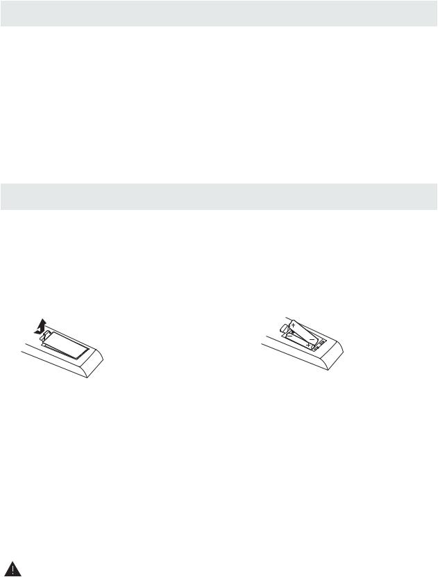
TOINSTALLTHEBATTERIES |
|
1. Open the battery door. |
2. Insert 2 "AA" batteries |
.
BATTERYREPLACEMENT
When the batteries become weak, the operating distance of the remote control is greatly reduced and you will need to replace the batteries.
 CAUTION : Danger of explosion if battery is incorrectly replaced.
NOTES
·If the remote control is not going to be used for a long time, remove the batteries to avoid damage caused by battery leakage corrosion.
·Do not mix old and new batteries. Do not mix ALKALINE, standard (CARBON-ZINC) or rechargeable (NICKEL-CADMIUM) batteries.
·Always remove batteries as soon as they become weak.
·Weak batteries can leak and severely damage the remote control.
WARNING:
Do not dispose batteries in a fire. Batteries may explode or leak.
Batteries shall not be exposed to excessive heat such as sunshine, fire or the like.
3
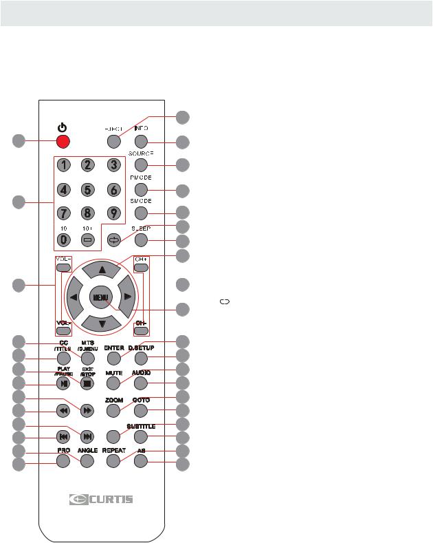
CONTROL REFERENCE GUIDE
REMOTE CONTROL
1
7
10
15
14
19
18
23
22
27
26
31
30
1.STANDBY
To switch on the TV or make the TV into standby mode.
22.EJECT
To eject a disc.
3 3.INFO
Show the information of the program you are watching.
4
4.SOURCE
Press this button to select an input source.
5
5.PMODE
6Press this button to select a picture mode for different
8 |
picture qualities. |
||||
6.SMODE |
|||||
|
9 |
||||
|
Press this button to select sound setting for different |
||||
12 |
|||||
sound effects. |
|||||
|
|
|
|
7.0-9 |
|
|
|
11 |
Allows you to change the channel of the TV. |
||
|
|||||
13 |
8. |
||||
Switches back and forth between the current and |
|||||
previous channels.
|
16 |
|
|
17 |
|
|
20 |
|
|
21 |
|
FAV |
24 |
|
25 |
||
|
||
EPG |
28 |
|
|
29 |
32
33
Universal Remote Code: 1218
9.SLEEP
To select the amount of time before your TV turns Off automatically.
10.VOL+/VOL-
Increases/Decreases the Volume control.
11.CH+/CH-
Skips to the next/previous channel on TV mode.
12.UP/DOWN/LEFT/RIGHT
Moves the cursor upward/downward/to the left/to the right when making a selection.
13.MENU
Displays the OSD Menu of the TV.
14.CC
Press the button to enter into the CC mode.
TITLE
To goto the title menu if the DVD disc has a title page.
15.MTS
To change among STEREO, MONO and SAP. If there is no second language available for the signal received, LCD Display audio will output to mono.
D.MENU
To show the menu of the DVD disc.
4

CONTROL REFERENCE GUIDE
REMOTE CONTROL
1
7
10
15
14
19
18
23
22
27
26
31
30
|
|
|
|
|
16.ENTER |
|
|
|
|
|
|
Press to confirm selections on a menu screen. |
|
|
|
|
|
|
17.D.SETUP |
|
|
|
|
|
|
Press this button to show the DVD SETUP menu. |
|
|
2 |
18.Play/Pause |
||||
|
Press this button to play or pause the DVD you’re watching. |
|||||
|
||||||
|
3 |
19.Exit |
||||
|
Press this button to exit the on screen display. |
|||||
|
4 |
Stop |
|
|||
|
|
|
|
|
Press this button to stop playing the DVD you’re watching. |
|
|
5 |
20.MUTE |
||||
|
6 |
Press this button to mute or restore sound. |
||||
|
21.AUDIO |
|||||
|
8 |
|||||
|
Press this button to change the audio language of the DVD. |
|||||
|
|
9 |
22. |
|
||
|
|
|
||||
|
12 |
|
||||
|
Fast reverse in DVD mode. |
|||||
|
|
|
|
11 |
23. |
|
|
|
|
Fast forward in DVD mode. |
|||
|
|
|||||
|
13 |
AddsFAV |
or Delete current channel from the favourite list. |
|||
|
16 |
|
|
17 |
|
|
20 |
|
|
21 |
|
FAV |
24 |
|
25 |
||
|
||
EPG |
28 |
|
|
29 |
32
33
Universal Remote Code: 1218
24.ZOOM
To select a screen display size on your TV in DVD mode.
25.GOTO
Press this button to start playing the disc program from the time you want.
26. 

Previous chapter in DVD mode.
27.

Next chapter in DVD mode.
28.EPG
Press this button to select the electronic programme guide.
29.SUBTITLE
To show the subtitle for the program you're watching.
30.PRO
To edit the program list of your DVD disc in DVD mode.
31.ANGLE
To select different angles to which the picture suits your preference.
32.REPEAT
Press this button for repeat the program.
33.AB
Press this button for repeat play point A and B.
5

CONTROLREFERENCE GUIDE
FRONT VIEW
1.Color Screen 2.Remote Sensor
Do not block this sensor or the remote control will not work. 3.Standby Indicator
Indicates whether the unit is ON or in STANDBY (OFF) mode.
Light in red: The unit is in STANDBY. Light in blue:The unit is turned ON. 4. Speakers
4 1 |
4 3 |
2 |
BACK VIEW
1.ON/OFF Switch
2.AC IN 100-240V~ 50/60Hz 3.Service Port
4.HDMI IN Jacks 5.VGA IN Jack 6.PC AUDIO IN Jack
7.COMPONENT1 IN Jack 8.COMPONENT2 IN Jack 9.Coax OUT Jack 10.S-Video IN Jack
(The S-Video's audio is the same as the AV1) 11.AV1 (VIDEO/ AUDIO L/R)in
12.AV2 (VIDEO/ AUDIO L/ R)in 13.TV ANTENNATerminal
1 |
2 |
3 |
4 |
5 |
6 |
8 |
9 |
12 |
13 |
7 10 11
ON
After you connect the power cord into the power socket, make sure the power cord is fully inserted into the unit. Then press the power ON/OFF switch to “ON” position as shown left.
6

CONTROL REFERENCE GUIDE
SIDE VIEW
11
8
9


 10
10
11.Disc Door
Insert discs to disc door
(Right direction: put the mirror side of the disc against yourself)
7
6
5
4
3
2
1. STANDBY Button
Press to turn the unit on and off.
2. SOURCEButton
Press to select the input source of the TV. 3. MENUButton
Press to display the on-screen TV menu.
4. CH- Button
Press to change the TV channels and down highlight selections on the menu screen.
5. CH+ Button
Press to change the TV channels and up highlight selections on the menu screen.
6. VOL- Button
Press to adjust the volume down.
7. VOL+ Button
Press to adjust the volume up.
8. Button 
Press to playing in DVD mode.
9. Button ►


Press to start pause or resume playback of a disc. lecture d'un disque.
10. Button 
Press to eject a disc.
7
CONNECTIONS
CONNECTING A TV ANTENNA / CABLE / SATELLITE
Toviewtelevisionchannelscorrectly,asignalmust bereceivedfromoneofthefollowingsources:
-Anindoororoutdooraerialantenna
-A cable system
-Asatellitesystem
NOTE
Forreceivingover-the-airTVbroadcasts,we recommend that you use an external fixed antenna. Should you require the use of a temporary antenna, pleaseensurethatyoupurchaseanantennawith sufficientabilitytoreceivein weaksignalareas. Only when you are in close proximity to a transmitter willatemporaryantennareproduceasignal as stronglyasafixedantenna.
CONNECTINGANA/VDEVICE
Toconnecttootherequipmentsuch asaVCR, camcorder,
Satellite,cableorTVantenna cable to TV ANTENNA terminal(cablenotincluded)
satellitesystem orcable,etc.
Connecting to a VCR / Camcorder / SatelliteSystem/Cable
ConnecttheAUDIOandS-VIDEOcable (notincluded)asshown.
Make sure you connect the cable from the other equipment( AUDIOOUT andS-VIDEOOUT )to thisunit( AV1's AUDIOIN and S-VIDEOIN ).
NOTE
Please refer to the user manual for the other equipmentformoreinformation.
To S-VIDEO IN jacks

 To AUDIO IN
jacks (AV1 IN)
To S-VIDEO OUT / AUDIO OUT jacks
CONNECTINGDEVICESWITHACOMPOSITE(YELLOWRCA-TYPE)
VIDEOOUTPUT
To connect A/V devices such as a VCR, video game system or camcorder.
ConnectingtoaVCR/ VideoGameSystem/Camcorder
ConnecttheAUDIO/VIDEOcable(notincluded)asshown.
Make sure you connect the cable from the other equipment ( AUDIO and VIDEOOUT ) to this unit
(AV1 orAV2 in)
NOTE
Please refer to the user manual for the other equipment for moreinformation.
ToAUDIO /VIDEO
OUTjacks |
ToAUDIO /VIDEO |
IN jacks (AV1 or AV2 IN)
8

CONNECTIONS
CONNECTINGAHIGH-DEFINITION(HD)SOURCEUSING COMPONENT CONNECTION
High-Definition(HD)DeviceswithcomponentvideooutputmustbeconnectedtotheYPbPr input. Connectthecomponentvideocableandaudiocable(notincluded)asshown.
Make sure you connect the component video cable and audio cable from the other equipment
COMPONENT OUT andAUDIO OUT to the unit COMPONENT1 IN or COMPONENT2 IN.
NOTE
WhenconnectingaDVDplayertothetelevision, thepictureresolutionissolelydependentupon
theresolutionsupportedbytheDVDplayerattached. DVDplayerresolutionsvaryfrom480ito1080i , andthistelevisioncansupportDVDplayersupto
amaximumresolutionof1080i .
* May require a subscription |
COMPONENT1 IN |
forreceivingHDchannels, |
or COMPONENT2 IN |
checkwithyourcable/satellite |
|
serviceprovider fordetails. |
|
ToCOMPONENT VIDEO OUT jacks
To COMPONENT AUDIO
OUT jacks
ToCOMPONENT |
VIDEOINjacks
ToCOMPONENT
AUDIO INjacks
CONNECTINGAHIGH-DEFINITION(HD)SOURCEUSINGHDMICONNECTION
HDMI(HighDefinitionMultimediaInterface)supportsbothvideoandaudioona singledigitalconnection for use with DVD players, DTV, set-top boxes and other digital AV devices. HDMI was developed to provide thetechnologiesof HighBandwidthDigitalContentProtection(HDCP)aswellas Digital VisualInterface
(DVI) in one specification. HDCP is used to protect digital content transmitted and received by DVI-compliantorHDMIcompliantdisplays.
HDMIhasthecapabilitytosupport standard,enhancedorhigh-definition videoplusstandardto multi-channelsurround-soundaudio.HDMIfeaturesincludeuncompresseddigital video,abandwidthof upto2.2gigabytespersecond(withHDTVsignals), oneconnector(insteadofseveralcablesand connectors),andcommunicationbetweentheAVsourceand AVdevicessuch asDTVs.
Connect the HDMI cable (not included) as shown:
Make sure you connect the cable from the sourceequipment( HDMIOUT )tothisunit ( HDMIIN ).
HDMI CABLE
(NOT INCLUDED)
To HDMI
INjack
To HDMI
OUT jack
9

CONNECTIONS
CONNECTING A PC
Connectthe15-pinD-SUBPC/VGAconnector fromyourcomputertothe15-pin D-SUBPC/VGA inputonthisunitusinga monitorcableandan audiocable(notincluded)asshown.
Make sure you connect the cable from the computer (VGA and AUDIO - PC OUT ) tothisunit
(VGA and AUDIO - PC IN ).
 TO AUDIO OUT jacks
 TO PC Connector
CONNECTING THEPOWERCORD
Youcanpoweryour TVunitbypluggingthepower cord intotheAC socket ontherearof
the unit and into a wall AC power outlet. Check that the rated voltage of your unit matches your local voltage.Makesurethatthe power cord isfullyinsertedintotheunit.
10

CONNECTIONS
Connection to a Home Theater Audio System
For BEST audio performance
Connecting to a Home Theater System Dolby Digital can deliver optimal 2 channel stereo or surround sound with five discrete full range channels plus a sixth channel for a subwoofer.
Enjoy optimal sound reproduction from your system with a Dolby Digital amplifier that incorporates a digital coaxial input. Connect an optional digital cable directly to the television’s Coax audio output to listen through all inputs except VGA.
The VGA does not support digital audio
How To Setup Digital Output
Press the MENU button on the remote control Press the right ►a rrow button to select AUDIO
Press the down ▼a |
rrow button to highlight |
SPDIF type right ►R |
aw or PCM |
|
|
12 |
|
|
|
6 |
|
Picture |
Audio |
Time |
Setup |
Sound Mode |
Standard |
Bass |
50 |
Treble |
50 |
Balance |
50 |
Surround |
Off |
SPDIF Type |
PCM |
AudioLanguage |
English |
SPDIF |
|
OUT |
Move |
Select |
MENU Exit |
|
|||||
|
Coax
11
 Loading...