


Model:PLDEDV3292-UK-B

CONTENTS
1SAFETYPRECAUTION
IMPORTANT
2SAFETY INSTRUCTION
3ACCESSORIES
4GETTINGSTARTED
WALL MOUNT
5INSTALLATION
CONTROL
6REFERENCE GUIDE
7CONNECTIONS
8INITIAL SETUP
9TV SETUP
|
|
1 |
|
|
|
|
|
|
|
|
|
|
LISTENING WITH HEADPHONE |
2 |
|
|
INTERFERENCES |
|
|
|
EXCLUSIVE IMPORTER |
|
|
|
|
|
|
|
|
3 |
|
|
|
|
|
|
|
|
|
|
|
3 |
|
|
|
|
|
|
|
|
|
|
|
4 |
|
|
|
|
|
|
|
|
|
|
Remote Control |
5 |
|
|
Front View |
9 |
|
|
Back View |
9 |
|
|
Side View |
10 |
|
|
|
|
|
|
|
|
|
|
Antenna Connection |
11 |
|
|
AV Connection |
11 |
|
|
YPbPr Connection |
12 |
|
|
HDMI Connection |
12 |
|
|
VGA Connection |
13 |
|
|
Headphone Connection |
13 |
|
|
Power Cord Connection |
13 |
|
|
COAX Connection |
14 |
|
|
USB Connection |
15 |
|
|
Insert a CI card |
15 |
|
|
|
|
|
|
|
|
|
|
Putting the Unit on a proper place |
16 |
|
|
Source Selection |
16 |
|
|
Turning the unit ON for the First Time |
16 |
|
|
|
|
|
|
|
|
|
|
TV(CHANNEL) Menu |
17 |
|
|
Picture Menu |
20 |
|
|
Sound Menu |
21 |
|
|
Lock System Menu |
23 |
|
|
Setup Menu |
24 |
|

CONTENTS
10 PC SETUP
ATV/SCART/
11HDMI/AV/YPbPr PC
12DVD MENU
13USB MENU
14DISPLAYMODE
15 SPECIFICATION
TROUBLE-
16SHOOTING GUIDE
PC Menu |
28 |
|
|
|
|
29
|
Discs handling |
30 |
|
|
|
|
|
|
|
|
|
|
Photo |
34 |
|
|
Music |
35 |
|
|
Movie |
35 |
|
|
Text |
36 |
|
|
|
|
|
|
|
|
|
|
PC Formats |
37 |
|
|
Video Formats |
38 |
|
|
|
|
|
|
|
|
|
|
|
39 |
|
|
|
|
|
|
|
|
|
|
TV Symptom |
40 |
|
|
DVD Symptom |
41 |
|
|
|
|
|
|
|
|
|
SAFETY CLASS :This is an IEC safety class I product and it must be grounded for safety.
SAFETY PRECAUTION
*CAUTION MARKING WAS LOCATED AT THE REAR PLACEMENT INFORMATION OF THE APPARATUS.
•Do not use this unit in places that are extremely hot, cold, dusty or humid.
•Do not restrict the airflow of this unit by placing it
somewhere with poor airflow, by covering it with a cloth, by placing it on bedding or carpeting.


 SAFETY INFORMATION
WARNING:TO REDUCE THE RISK OF ELECTRIC SHOCK DO NOT REMOVE COVER OR BACK NO USER SERVICEABLE PARTS INSIDE.
REFER SERVICING TO QUALIFIED SERVICE PERSONNEL.
•When connecting or disconnecting the AC power cord, grip the plug and not the cord itself. Pulling the cord may damage it and create a hazard.
•When you are not going to use the unit for a long period of time, disconnect the AC power cord.
The lightning flash with arrowhead symbol, within an equilateral triangle,is intended to alert the user to the presence of uninsulated dangerous voltage”within the product's enclosure
that may beof sufficient magnitude to constitute a risk of electric shock to persons.
The exclamation point within an equilateral Triangle is intended to alert the user to The presence of important operating and
maintenance (servicing) instructions in the literature accompanying the appliance.
CAUTION
INVISIBLE LASER RADIATION WHEN |
This product |
|
Contains a low |
||
OPEN AND INTERLOCKS DEFEATED |
||
power laser device. |
||
AVOID EXPOSURE TO BEAM |
||
|
CLASS 1 LASER
PRODUCT
CAUTION
• DANGER OF EXPLOSION IF BATTERY IS INCORRECTLY REPLACED. REPLACE ONLY WITH THE SAME OR EQUIVALENT TYPE.
•USE OF CONTROLS OR ADJUSTMENTS OR PERFORMANCE OF PROCEDURES OTHER THAN THOSE SPECIFIED MAY RESULT IN HAZARDOUS RADIATION EXPOSURE.
WARNING:
•TO REDUCE THE RISK OF FIRE OR ELECTRIC SHOCK, DO NOT EXPOSE THIS APPLIANCE TO RAIN OR MOISTURE.
TO REVENT FIRE OR SHOCK HAZARD, DO NOT
•EXPOSE THIS UNIT TO RAIN OR MOISTURE. DO NOT PLACE OBJECTS FILLED WITH LIQUIDS ON OR NEAR THIS UNIT.
•SHOULD ANY TROUBLE OCCUR, DISCONNECT THE AC POWER CORD AND REFER SERVICING TO A QUALIFIED TECHNICIAN.
CONDENSATIONINFORMATION
•When left in a heated room where it is warm and damp, water droplets or condensation may form inside the equipment. When there is condensation inside the unit, the unit may not function normally. Let the unit stand for 1-2 hours before turning the power on or gradually heat the room and let the unit dry before use.
RATINGPLATELOCATION
The rating plate is located on the rear of the unit.
FCCSTATEMENTS
NOTE: This unit has been tested and found to comply with the limits for a Class B digital device, pursuant to Part 15 of the FCC Rules. These limits are designed to provide reasonable protection against harmful interference in a residential installation.
This unit generates, uses and can radiate radio frequency energy and, if not installed and used in accordance with the instructions, may cause harmful interference to radio communication. However, there is no guarantee that interference will not occur in a particular installation. If this unit does cause harmful interference to radio or television reception, which can be determined by turning the unit off and on, the user is encouraged to try to correct the interference by one or more of the following measures:
-Reorient or relocate the receiving antenna.
-Increase the separation between the unit and receiver.
-Connect the unit into an outlet on a circuit different from that to which the receiver is connected.
-Consult the dealer or an experienced radio/TV technician for help.
WARNING:
Changes or modifications to this
unit not expressly approved by the party responsible for compliance could void the user authority
to operate the unit.
“HDMI, the HDMI logo and High-Definition Multimedia Interface are trademarks or registered trademarks of HDMI Licensing LLC.”
1

IMPORTANT SAFETY INSTRUCTIONS
1)Read these instructions. 2)Keep these instructions. 3)Heed all warnings.
4)Follow all instructions.
5)Do not use this apparatus near water. 6)Clean only with a dry cloth.
7)Do not block any ventilation openings. Install in accordance with the manufacturer's instructions.
8)Do not install near any heat sources such as radiators, heat registers, stoves, or other apparatus (Including amplifiers) that produce heat.
9)Do not defect the safety purpose of the polarized or grounding-type plug.
A polarized plug has two blades with one wider than the other.
A groundingtype plug has two blades and a third grounding prong.
The wide blade or the third prong is provided for your safety.
If the provided plug does not fit into your wall outlet, consult an electrician for replacement of the obsolete outlet.
10)Protect the power cord from being walked on or pinched particularly at plugs, convenience receptacles, and the point where they exit from the apparatus.
11)Only use attachments / accessories specified by the manufacturer.
LISTENING WITH HEADPHONE (EARPHONE) (Not Included)
Connect the plug of the stereo headphone (earphone) into the EARPHONE output(marked phones) before use the unit.
CAUTION: Hearing experts advice against exposure to continuous extended play at loud volume levels while using headphone (earphone), possible hearing loss may result.
If you experience a ringing in the ears, reduce volume or discontinue use. We want you listening for a life time.
INTERFERENCES
12)Use only with the cart, stand,
tripod, bracket, or table specified by the manufacturer,
or sold with the apparatus.  When a cart is used, use caution when
  moving the cart / apparatus combination to avoid injury from tip-over.
13)Unplug this apparatus during lightning Storms or when unused for long periods of time.
14)Refer all servicing to qualified service personnel. Servicing is required when the apparatushas been damaged in any way, such as the power cord or plug is damaged, liquid has been spilled or objects have fallen into the apparatus, the apparatus has been exposed to rain or moisture, does not operate normally, or has been dropped.
15)To prevent electric shock, ensure the grounding pin on the AC cord power plug is securely connected.
IMPORTANT!
It is recommended not to leave a mobile phone near the unit in order to avoid electromagnetic interference in the speakers.
2
ACCESSORIES |
|
Please check and identify the supplied accessories. |
|
Remote control .................................................................................................................. |
x 1 |
Battery(AAA).................................................................................................................... |
x 2 |
Warranty Card ................................................................................................................ |
x 1 |
Instruction Manual........................................................................................................... |
x 1 |
Column bracket and 4 column bracket screws..................................................................... |
x 1 |
Base stand and 4 base stand screws................................................................................. |
x 1 |
Fixed base sheet............................................................................................................. |
x 1 |
Screw driver ................................................................................................................... |
x 1 |
Mini AV cable and mini YPbPr cable .................................................................................. |
x 1 |
GETTING STARTED
USING THE REMOTE CONTROL
·Point the remote control at the remote sensor located on the unit.
·When there is a strong ambient light source, the performance of the infrared remote sensor ·may be degraded, causing unreliable operation.
·The recommended effective distance for remote operation is about 16 feet (5 meters).
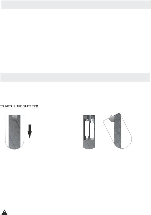
1.Open the battery door 2.Insert2"AAA"batteries
BATTERY REPLACEMENT
When the batteries become weak, the operating distance of the remote control is greatly reduced and you will need to replace the batteries.
 CAUTION : Danger of explosion if battery is incorrectly replaced.
NOTES
·If the remote control is not going to be used for a long time, remove the batteries to avoid damage caused by battery leakage corrosion.
·Do not mix old and new batteries. Do not mix ALKALINE, standard (CARBON-ZINC) or rechargeable (NICKEL-CADMIUM) batteries.
·Always remove batteries as soon as they become weak.
·Weak batteries can leak and severely damage the remote control.
WARNING :
Do not dispose batteries in a fire. Batteries may explode or leak.
Batteries shall not be exposed to excessive heat such as sunshine, fire or the like.
3
WALL MOUNT INSTALLATION
INSTALLING / REMOVINGTHEBASESTAND
WARNING : The TV Display is very fragile and, must be protected at all times when removing the base
|
Stand. |
|
|
Besurethatno hardorsharpobject oranythingthatcouldscratch ordamagetheTV display comesinto |
|
||
contact with it Do. NOT exert pressure on the front of the unit at any time because the screen could crack |
. |
||
1 |
. Disconnectallcablesorcordsconnectedtothe unit. |
|
|
2 |
. Lay the unit down on a flat surface with the back side facing up Please. make sure to place a soft |
|
|
|
cushionedmaterial suchasapilloworthickpiece offoam beneaththescreen |
|
|
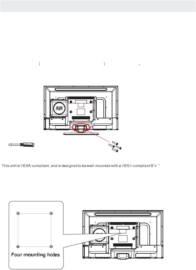
3 |
. To remove the base stand loosen, |
screws off the holes then pull downwards to release |
|
|
the base stand. |
|
|
MOUNTINGONTHEWALL
4
(200mmx100mm)mountingkitdesigned forflat-panelTVs (notsupplied).Mountthisunit accordingto
theinstructionsincludedinthemounting kit.
Length of screw should not exceed 8 mm.
NOTE
Removethe basestandbeforemountingtheunitonthe wall.
8”
4”


 M6
M6


4
CONTROL REFERENCE GUIDE
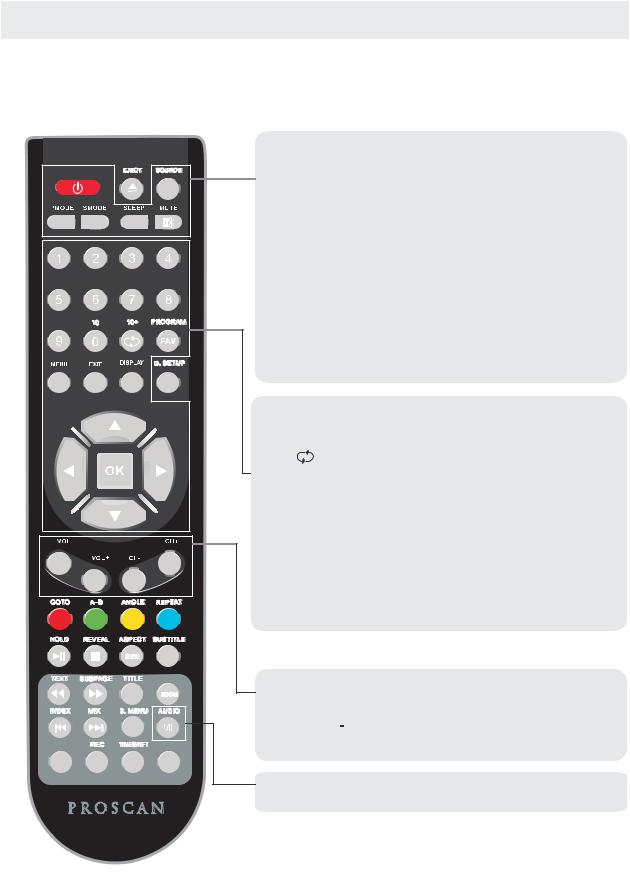
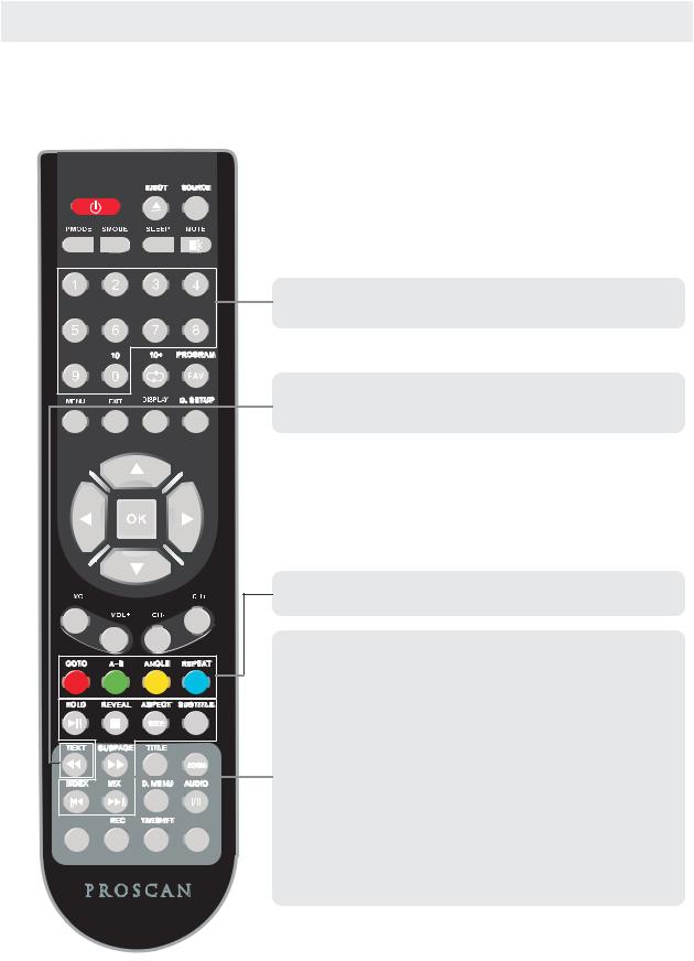
REMOTE CONTROL
TV MODE:
STANDBY
STANDBY |
GUIDE
MEDIA |
TV/RADIO |
Turn the TV ON or OFF.
SOURCE
Press to cycle through the input source
PMODE
Press repeatedly to cycle through the available video picture modes
SMODE
Press to cycle through the different sound settings.
SLEEP
Select amount of time.Let your TV turn off automatically. MUTE
Press to mute the sound.Press again or pressV+ to un-mute the TV.
NUMBER BUTTONS
Press 0-9 to select a TV channel directly when you are watching TV.The channel change after 2 seconds.
Return to the previous channel viewed.
MENU
Brings up the main TV menu to the screen. EXIT
Exit the main TV menu to the screen. DISPLAY
Press to display the source and channel’s information.
THUMBSTICK(p/q/t/u/OK)
Allows you to navigate the on-screen menus and adjust the system settings to your preference.
VOL+/VOL-
Press to increase/decrease the sound level.
CH+/CH-
Press to scan through channels.
I/II
Press to search the NICAM modes.
5
CONTROL REFERENCE GUIDE
REMOTE CONTROL
TELETEXT MODE:
STANDBY
NUMBER BUTTONS
Press 0-9 to select a teletext page.
|
GUIDE |
MEDIA |
TV/RADIO |
TEXT
Press to switch between TV and Teletext mode.
COLOUR BUTTONS
Select 4 Preferred TELETEXT page.
HOLD
Freeze the current page.
REVEAL
Reveal or hide the hidden words. SIZE
Change the picture size.
SUBTITLE
To display subtitle.
SUBPAGE TELETEXT Subpage. INDEX
Request index page when index link is valid. MIX
TV and TXT pictures are mixed together in transparent background.
6
CONTROL REFERENCE GUIDE
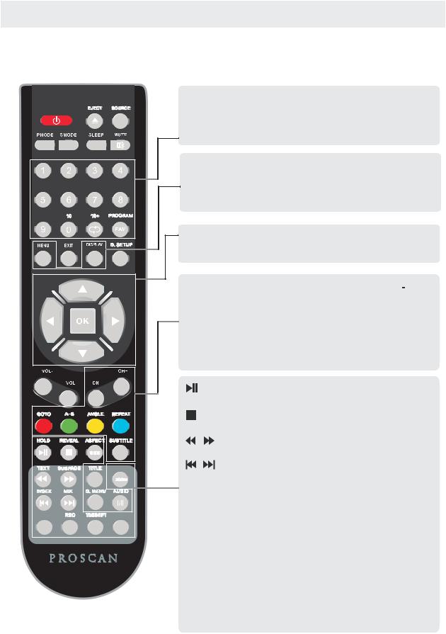
REMOTE CONTROL
DTV MODE:
STANDBY
|
GUIDE |
MEDIA |
TV/RADIO |
NUMBER BUTTONS
Press 0-9 to select a channel.
FAV
Press to increase/decrease your favourite program in DTV mode
MENU
Brings up the main DTV menu to the screen.
DISPLAY
Press to display the source and channel’s information.
THUMBSTICK(p/q/t/u/OK)
Allows you to navigate the on-screen menus and adjust the system settings to your preference.
CH+/CH-
When watching a channel,changes the channel.
COLOUR BUTTONS
Colour buttons(respectively red,green,yellow and blue) used in a few sub-menus.
SUBTITLE
To display subtitle.
PLAY/PAUSE in TIMESHIFT and MEDIA mode.
Stop in MEDIA mode or exit the REC or TIMESHIFT mode.
Fast backward and forward key in MEDIA mode.
Jump to previous and next track in MEDIA mode.
ASPECT
Press to change the screen scale.
EPG
Launches the EPG(Electronic Program Guide) in DTV mode.
MEDIA
Press to select MEDIA mode.
REC
Record the program in DTV mode.
TIMESHIFT
Press to select TIMESHIFT function.
TV/RADIO
Select TV or Radio modes.
7
CONTROL REFERENCE GUIDE
REMOTE CONTROL
DVD MODE:
STANDBY |
|
GUIDE |
MEDIA |
TV/RADIO |
 EJECT
EJECT
To eject the disc.
NUMBER BUTTONS
Numerical buttons for various data.
PROGRAM
Program a disc playing in a desired sequence.
DISPLAY
Press to display the DVD information of DVD mode.
D.SETUP
Used for selecting programs.It may also be used to execute connands.
THUMBSTICK(p/q/t/u/OK)
Allows you to navigate the on-screen menus and adjust the system settings to your preference.
GOTO
It is possible to get access to any point on the directly using the ‘GOTO’menu.
Press GOTO to access the ‘GOTO’menu.
A-B
This button enables you to repeat a selected section from the disc.
ANGLE
Selects various camera angles for certain scenes or passages on the DVD during playback.
REPEAT
Press REPEAT to cycle through the repeat play options.
SUBTITLE
Select a different subtitle language(the DVD disc must have the subtitle you selected)
TITLE
When DVD is playing,brings up the Title Menu.
ZOOM
In play state,press ZOOM,the player will zoom in the picture one time.
D.MENU
DVD disc menu Access to menu.
AUDIO
AUDIO selection buttons in DVD mode.
PLAY/PAUSE in DVD mode.
DVD STOP
Jump to previous and next track.
Fast backward and forward key.
8
CONTROL REFERENCE GUIDE
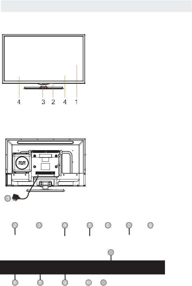
FRONT VIEW
1.Color Screen 2.Remote Sensor
Do not block this sensor or the remote control will not work. 3.Standby Indicator
Indicates whether the unit is ON or in STANDBY (OFF) mode.
Light in red: The unit is in STANDBY. Light in blue:The unit is turned ON. 4. Speakers
BACK VIEW
1.Power Cord.
2.Headphone: Connect the earphone. 3.SCART:Connect the SCART jack of VCR
or DVD.
4.PC AUDIO: Connect the Audio output jack of PC.
5.VGA: Connect a computer to these jacks. 6.COAX: COAX OUT Jack.
7.RF: Connect the antenna. 8.HDMI1/2/3: Connect the HDMI output
jack of DVD.
9.USB: Connect to portable usb device. 10.AV:AV IN Jack 11.YPbPr:COMPONENT IN Jack 12.CI:Connect to the CI card.
Head |
SCART |
PC |
VGA |
COAX |
RF |
HDMI1 |
|
Phone |
Audio |
||||||
|
|
|
|
|
|||
|
|
|
|
|
|
|
12
HDMI2 HDMI3 USB
CI
AV YPbPr
11
9
CONTROL REFERENCE GUIDE
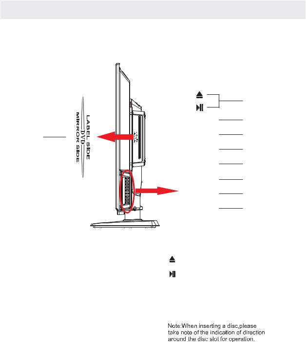
SIDE VIEW
|
|
8 |
|
VOL+ |
7 |
9 |
VOL- |
6 |
|
CH+ |
5 |
4
3
2
1
1. STANDBY Button
Turn on the TV by pressing the button once. Press the button again to turn off the TV.
2. SOURCEButton
Press to select the input source of the TV. 3. MENUButton
This button activates the On Screen Display (OSD). If a sub-menu is active, pressing this button will exit the OSD.
4. CH- Button
This button changes the TV channel down.If the OSD is active,this button functions as down for the menu.
5. CH+ Button
This button changes the TV channel up.If the OSD is active,this button functions as up for the menu. 6. VOL- Button
This button decreases the TV's volume.If a sub-menu is active,pressing this button will move the selection left. 7. VOL+ Button
This button increases the TV's volume.If a sub-menu is active,pressing this button will move the select right.
10
CONNECTIONS
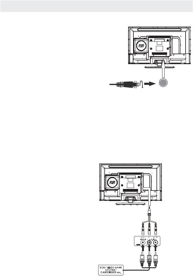
CONNECTING A TV ANTENNA / CABLE / SATELLITE
Toviewtelevisionchannelscorrectly,asignalmust bereceivedfromoneofthefollowingsources:
-Anindoororoutdooraerialantenna
-A cable system
-Asatellitesystem
NOTE
Forreceivingover-the-airTVbroadcasts,we recommend that you use an external fixed antenna. Should you require the use of a temporary antenna, pleaseensurethatyoupurchaseanantennawith sufficientabilitytoreceivein weaksignalareas. Only when you are in close proximity to a transmitter
willatemporaryantennareproduceasignal as
stronglyasafixedantenna.
Satellite,cableorTVantenna cable to TV ANTENNA
terminal(cablenotincluded)
CONNECTING AN A/V DEVICE
Toconnecttootherequipmentsuch asaVCR, camcorder,satellitesystem orcable,etc.
CONNECTING DEVICES WITH A COMPOSITE VIDEO OUTPUT
To connect A/V devices such as a VCR, video game system or camcorder.
Connecting to a VCR / Video Game System / Camcorder
ConnecttheAUDIO/VIDEOcable(notincluded)asshown.
Make sure you connect the cable from the other equipment ( AUDIO and VIDEO OUT ) to this unit
(AV in)
NOTE
P.lease refer to the user manual for the other equipment for moreinformation.
ToAUDIO /VIDEO
OUTjacks |
ToAUDIO /VIDEO |
IN jacks
11
 Loading...