

Page 1

Page 2

Introduction
The 22" wheeled string trimmer was intended
for clearing heavy growth from unimproved
land. This model has a blade brake clutch feature. When the control lever is released, the
trimmer line will stop rotating, but the engine
will continue running. See Figure 1-1.
22” STRING TRIMMER
Model 24A-253-401
1. Bend the pre-cut line in a U shape and insert it
through the outer pair of hoops on one side of
the spindle, keeping both sides of the “U”
equal. See Figure 1-3.
1
MTD also manufactures an 18" string trimmer
that does not have the blade brake clutch feature. When the control lever is released, the
engine is stopped as it would be on a conventional lawn mower. The primary difference
between the two models is that the control
cable on the 22" version is replaced with a
simple spring on the 18" model. They are otherwise very similar.
Trimmer Line
The trimmer line is a fixed length and can
easily be replaced following the diagram on
the front of the trimmer base assembly. See
Figure 1-2.
2. Double the lines back through the center
hoop. The string will now be in the shape of a
pretzel. See Figure 1-4.
1-1
Page 3
3. Uncross the two lines so that they are roughly
parallel.
The line will be trimmed to final length by the
blade mounted under the deflector.
. All three nuts and bolts that secure the glide
ball to the spindle assembly can be removed
using a pair of 7/16" wrenches.
NOTE
Do not re-use the original hardware, new
hardware will be included with the glide ball.
Spindle
NOTE
The spindle cannot be serviced, and must be
replaced as a unit if it gets damaged. See Figure 1-6.
• 22" trimmer use .150" line, part number:
• 18" trimmer uses .130" line, part number:
The above numbers are for pre-cut lengths,
packaged in a quantity of ten. Bulk line may
also be used.
Glide Ball
The glide ball is available as service part number: 982-0143. See Figure 1-5
OEM-743-0110
OEM-743-0111
NOTE
NOTE
The cutting height is adjusted by sliding the
disc that the trimmer line is attached to up or
down the spindle shaft.
The disc is held in position by two wing nuts,
that must be loosened before making a height
adjustment, and retightened to hold that
adjustment.
The glide ball remains fixed, and the disc
moves in relation to the glide ball.
1-2
The wing nuts cannot be removed from their
studs: the threads are peened.
Page 4

1. Remove the nuts from the four carriage bolts
that hold the deflector to the trimmer base
using a 7/16" wrench. See Figure 1-7.
2. Rotate the deflector so that the wide part of
the center hole in the deflector will fit past the
spindle. See Figure 1-8.
1
Figure 1-9.
4. Remove the belt keeper from the idler pulley
by loosening the lock nut with a 1/2" wrench.
See Figure 1-10.
3. Remove the deflector. See Figure 1-9.
Figure 1-10.
1-3
Page 5
5. Remove the V-belt from the idler pulley. See
Figure 1-11.
9. Remove the hex nut and hex bolt that hold the
tensioner pulley arm to the trimmer base
using a 1/2" wrench.
NOTE
Record the mounting hardware as you
remove it. See Figure 1-13.
6. Grasp the idler bracket assembly and pull
inward until the belt can be removed from the
spindle assembly.
The torsion spring applies tension to the belt
brake at rest, and must be moved away from
the belt for removal.
7. Unhook the “Z” fitting (at the end of the
engagement cable) from the idler bracket.
See Figure 1-12.
8. Loosen the center hex bolt securing the spindle assembly to the trimmer base from the
top, using a 1/2" wrench.
Figure 1-11
NOTE
10. Remove the remaining five bolts which
secure the spindle to the trimmer base using
a 1/2" wrench.
Three of these bolts will also hold the belt
keeper in position. See Figure 1-14.
Figure 1-13.
NOTE
Figure 1-12
Figure 1-14.
11. Remove the center bolt from the spindle.
12. Remove the spindle.
13. Follow instructions in the reverse order to
assemble.
1-4
Page 6
BELT REPLACEMENT
There are two different crankshaft pulleys that
have been used in string trimmer production.
Some string trimmers have engines equipped
with heavy engine flywheels, while other
engines have light engine flywheels. Because
there is not a conventional blade to add rotating mass to the crankshaft, a flywheel was
added to the crankshaft pulley used on the
engines that have light engine flywheels. The
pulley flywheel is large enough that the belt
will not fit over it. The belt will fit over the pulley which does not have a flywheel attached
to it. Because of this difference, there are two
different procedures for replacing the drive
belt. The first steps of both procedures are
the same. See Figure 1-15.
NOTE
5. Remove the carriage bolts and the deflector.
Remove the belt keeper from the tensioner
pulley by loosening the lock nut with a 1/2"
wrench.
6. Remove the belt keeper from the tensioner
pulley by loosening the lock nut with a 1/2"
wrench.
7. Remove the V-Belt from the Idler pulley.
8. Grasp the idler bracket assembly and pull
inward until the belt can be removed from the
spindle assembly.
NOTE
The torsion spring applies tension to the belt
brake at rest, and must be moved away from
the belt for removal.
9. Unhook the “Z” fitting (at the end of the
engagement cable) from the idler bracket.
See Figure 1-16.
1
Figure 1-15.
IMPORTANT:
been running.
1. Disconnect and ground the spark plug wire.
2. Drain the fuel tank.
3. Position the trimmer so the rear edge of the
trimmer base is resting securely on a work
bench, and pivot the handle down.
The handle should be securely weighted
down, so the trimmer stands on end.
4. Remove the hex nuts from the carriage bolts
that secure the deflector shield to the trimmer
base using a 7/16" wrench.
Allow the engine to cool if it has
NOTE
Figure 1-16.
10. Loosen, but do not remove the three nuts that
secure the belt keeper, and spindle assembly
to the trimmer base using a 1/2" wrench.
TRIMMERS WITH PULLEY FLYWHEELS
NOTE
For trimmers equipped with pulley fly wheels,
perform steps 1 through 10, then follow these
steps;
1-5
Page 7

1. Secure the pulley flywheel so that it will not
spin during removal of the crankshaft bolt.
See Figure 1-17.
Figure 1-17.
2. Remove the crankshaft bolt using a 5/8"
wrench.
3. Remove the bolt from the left side of the axle
using a 7/16" wrench.
TRIMMERS WITH STANDARD CRANkSHAFT
PULLEYS
NOTE
For trimmers equipped with standard crank-
shaft pulleys, follow steps 1 through 10, then
complete these steps;
1. Loosen, but do not remove the remaining nuts
that fasten the spindle and belt tensioner
bracket to the trimmer base using a 1/2"
wrench. See Figure 1-19.
4. Remove the left wheel and slide the right
wheel and axle out of the trimmer frame. See
Figure 1-18.
Figure 1-18.
5. Roll the belt off of the pulley flywheel.
6. Slip the pulley flywheel off of the engine crank
shaft.
Figure 1-19.
2. Loosen, but do not remove the center bolt that
fastens the spindle to the trimmer frame using
a 1/2" wrench.
3. Loosen, but do not remove the three bolts that hold
the engine and engine pulley belt keeper to the
trimmer frame, using a 1/2" wrench. See Figure 1-
20.
7. Remove the belt.
Follow the instructions in the reverse order to
install the belt.
Figure 1-20.
1-6
Page 8
4. Roll the belt off of the crankshaft pulley, and
slip the belt between the pulley and the rear
axle. See Figure 1-21.
Figure 1-21.
5. Remove the belt from the spindle pulley.
6. Follow hte instructions in the reverse order to
install the belt.
There is a stop welded to the axle where it
passes through the right hand side of the trimmer base. This stop will not allow the axle to
slide or rotate. See Figure 1-23.
Figure 1-23.
There is a removable spacer and wave
washer between the left hand side wheel and
the trimmer base. See Figure 1-24.
1
The belt has been updated from part number
754-0489 to part number 754-0625. The new
belt is more resistant to stretching.
The control cable is secured to the axle, make
certain it is clear of rotating parts.
WHEELS AND AXLE
Each wheel can be removed by taking off a
single bolt and washer, using a 7/16" wrench.
See Figure 1-22.
NOTE
NOTE
Figure 1-24.
To remove the axle;
1. Remove the left hand side wheel bolt.
2. Slide the axle and wheel to the right, as
described in the belt removal section.
OTHER FEATURES
Figure 1-22.
The control handle on the 22" model is
equipped with a safety lock-out. See Figure 1-
25.
1-7
Page 9

Figure 1-25.
Figure 1-26.
There is a debris screen over the cooling fan.
Its presence is necessary to prevent the cooling fins from getting clogged. Customers
should not operate the trimmer without the
screen in place. See Figure 1-26.
A single wing nut holds the screen in place,
and is easily removed for cleaning.
1-8
Page 10

CHORE PERFORMERS
2-1. EDGER.
the operation in both positions after making
any adjustment to the rod. Secure lower clutch
rod with flat washer and hairpin clip when
adjustment is correct.
2
WARNING
When operating the edger, stop engine immediately and readjust the clutch rod if blade
turns with blade clutch/depth lever in the disengaged position.
2-1.1 Checking the Clutch Rod Adjustment.
The clutch rod on your edger has been preadjusted at the factory. Before operating the
edger, check the adjustment of the clutch rod
as follows.
1. Disconnect the spark plug wire and move it
away from the spark plug.
2. With the blade clutch/depth control lever in the
disengaged position (notch nearest the operator’s position), carefully pull the recoil starter
rope. The belt on the edger should not turn. If
the belt (and blade) turns, remove the hairpin
clip and flat washer, and remove the lower
clutch rod from the pivot arm extension. See
Figure 2-2. Turn the clutch rod one or two turns
clockwise to shorten the rod. Insert lower
clutch rod into pivot arm extension, and
recheck the adjustment.
3. Check to be certain the blade clutch/depth
control lever can be moved to the furthest
notch forward. If not, remove the hairpin clip
and flat washer, and turn the clutch rod one or
two turns clockwise to shorten the rod. Insert
lower clutch rod into pivot arm extension, and
recheck the adjustment. Be certain to recheck
2-1.2 Belt Removal and Replacement.
1. Remove belt guard assembly at engine pulley
by first removing hex nuts and lock washers.
See Figure 2-3.
2-1
Page 11
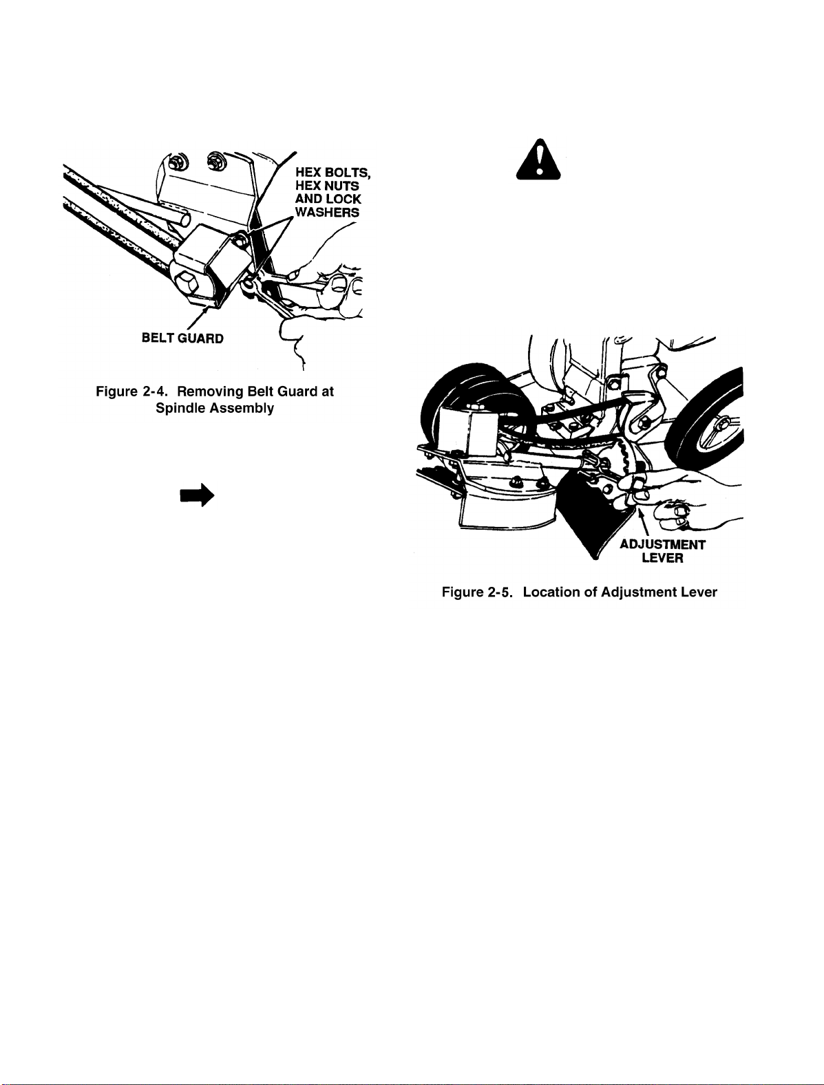
2. Remove belt guard at spindle assembly by
removing two hex bolts, lock washers and hex
nuts. See Figure 2-4.
3. Remove old belt and reassemble with new
belt, part number 754-0142.
release adjustment lever on pivot bracket and
rotate spindle housing. Place adjustment lever
in notch desired. See Figure 2-5.
CAUTION
If wheels are not adjusted, the blade will hit the
left front wheel causing the belt to slip.
2. When the blade is adjusted toward the horizontal position, the front wheels must also be
adjusted. Remove two hairpin clips and slide
spacer and wheel to the right. Reinsert hairpin
clips.
NOTE
While the belt cover is removed, it is a good
idea to apply a little grease to the pivot point on
belt cover.
2-1.3 Blade Plane Adjustment.
1. The cutting blade can be adjusted to eight
positions from vertical to horizontal. To adjust,
2-2
Page 12

CHORE PERFORMERS
2
2-3
Page 13

2-4
Page 14
TILLERS
3-1. GENERAL.
For further information regarding this section,
refer to Technical Service Video “Chain Case
Teardown 410- 420 Tiller.”
3-1.1 Tillers are a precision built machine designed
for seed bed preparation, cultivating, furrowing
and mulching. They are engineered to minimize the hardest work in the vegetable or
flower garden, to till the soil for planting and
cultivating and to perform many other useful
labor saving tasks in the garden.
3-1.2 The operation of a tiller can be relatively easy if
the operator understands the basic concept of
tilling procedure and the limitations of the
equipment. Carefully note the following:
CAUTION
Be sure the area to be tilled is free of damagecausing debris. If you are working in soil of
doubtful content, till at SLOW speed and be
alert for any obstruction and be ready to
release the clutch lever instantly.
1. The tiller is not intended to be used in small,
confined spaces where hand spading is more
practical. Tillers are designed to operate in
open areas where there is a big job to do and
where there is freedom of movement.
2. While the tiller can be used on sod covered
ground, it is intended to work in open ground.
On sod covered ground the tiller will want to
buck and run and will require considerable
physical effort by the operator.
3. Do not try to hold back on the tiller to restrict its
movement. The basic idea is to let the depth
bar restrain the forward movement of the tines
and in so doing, cause the tines to dig rather
than run. Thus, it is essential that you use the
depth bar properly.
5. To begin operation of the tiller, proceed as follows:
a. With the depth bar set and staked into the
soil and with the clutch in the neutral position, start the engine.
b. Push down on the handles to drive the
depth bar firmly into the ground.
c. With the engine running at SLOW speed,
tilt the tiller back slightly to lift the tines off
the ground, engage the clutch lever slowly
to start the tines rotating and then slowly
lower the tines into the ground.
6. The rotation speed of the tines is determined
by the engine speed and thus is controlled by
the throttle control. Tilling should be done at
SLOW engine speed and increased only if the
ground conditions permit.
7. Under some ground conditions the tiller may
want to bog down. In this case raise and lower
the handles. This motion helps the tines dig out
and move forward and also releases some of
the restraint of the depth bar.
8. Do not try tilling ground that is overly wet. Wait
until the ground is dry enough to crumble
rather freely.
9. Till using a criss-cross pattern. Till in one direction with parallel paths and then till across
them at a 90 degree angle.
10. In making the first cut in untilled ground, the
tiller will track a straight path rather easily.
However, on subsequent passes, there will be
a tendency for the tines to work toward the
loose soil. Moving the handles side to side
should help maintain a straight path. If you use
a criss-cross pattern you need not till the parallel paths as close and therefore the straight
path problem is practically eliminated.
3
4. To use the tiller, move it (with the depth bar up
or in the released position) to the area to be
tilled. Once in position, lower the depth bar or
wheels to the approximate digging depth you
want. If you are going to dig deep on untilled
ground it is better to make several passes, digging deeper on each pass.
3-2. MODEL 031 FRONT TINE TILLER.
3-2.1 This tiller has been manufactured with 2 HP
and 3 HP engines. The 2 HP tiller is Model
020. The 3 HP is 030. Model 031 is basically
the same as the 030 except for the handle
panel and controls. The chain case is sealed at
the factory and there is no need to check the
3-1
Page 15

TILLERS
3-1. GENERAL.
For further information regarding this section,
refer to Technical Service Video “Chain Case
Teardown 410- 420 Tiller.”
3-1.1 Tillers are a precision built machine designed
for seed bed preparation, cultivating, furrowing
and mulching. They are engineered to minimize the hardest work in the vegetable or
flower garden, to till the soil for planting and
cultivating and to perform many other useful
labor saving tasks in the garden.
3-1.2 The operation of a tiller can be relatively easy if
the operator understands the basic concept of
tilling procedure and the limitations of the
equipment. Carefully note the following:
CAUTION
Be sure the area to be tilled is free of damagecausing debris. If you are working in soil of
doubtful content, till at SLOW speed and be
alert for any obstruction and be ready to
release the clutch lever instantly.
1. The tiller is not intended to be used in small,
confined spaces where hand spading is more
practical. Tillers are designed to operate in
open areas where there is a big job to do and
where there is freedom of movement.
2. While the tiller can be used on sod covered
ground, it is intended to work in open ground.
On sod covered ground the tiller will want to
buck and run and will require considerable
physical effort by the operator.
3. Do not try to hold back on the tiller to restrict its
movement. The basic idea is to let the depth
bar restrain the forward movement of the tines
and in so doing, cause the tines to dig rather
than run. Thus, it is essential that you use the
depth bar properly.
5. To begin operation of the tiller, proceed as follows:
a. With the depth bar set and staked into the
soil and with the clutch in the neutral position, start the engine.
b. Push down on the handles to drive the
depth bar firmly into the ground.
c. With the engine running at SLOW speed,
tilt the tiller back slightly to lift the tines off
the ground, engage the clutch lever slowly
to start the tines rotating and then slowly
lower the tines into the ground.
6. The rotation speed of the tines is determined
by the engine speed and thus is controlled by
the throttle control. Tilling should be done at
SLOW engine speed and increased only if the
ground conditions permit.
7. Under some ground conditions the tiller may
want to bog down. In this case raise and lower
the handles. This motion helps the tines dig out
and move forward and also releases some of
the restraint of the depth bar.
8. Do not try tilling ground that is overly wet. Wait
until the ground is dry enough to crumble
rather freely.
9. Till using a criss-cross pattern. Till in one direction with parallel paths and then till across
them at a 90 degree angle.
10. In making the first cut in untilled ground, the
tiller will track a straight path rather easily.
However, on subsequent passes, there will be
a tendency for the tines to work toward the
loose soil. Moving the handles side to side
should help maintain a straight path. If you use
a criss-cross pattern you need not till the parallel paths as close and therefore the straight
path problem is practically eliminated.
3
4. To use the tiller, move it (with the depth bar up
or in the released position) to the area to be
tilled. Once in position, lower the depth bar or
wheels to the approximate digging depth you
want. If you are going to dig deep on untilled
ground it is better to make several passes, digging deeper on each pass.
3-2. MODEL 031 FRONT TINE TILLER.
3-2.1 This tiller has been manufactured with 2 HP
and 3 HP engines. The 2 HP tiller is Model
020. The 3 HP is 030. Model 031 is basically
the same as the 030 except for the handle
panel and controls. The chain case is sealed at
the factory and there is no need to check the
3-1
Page 16
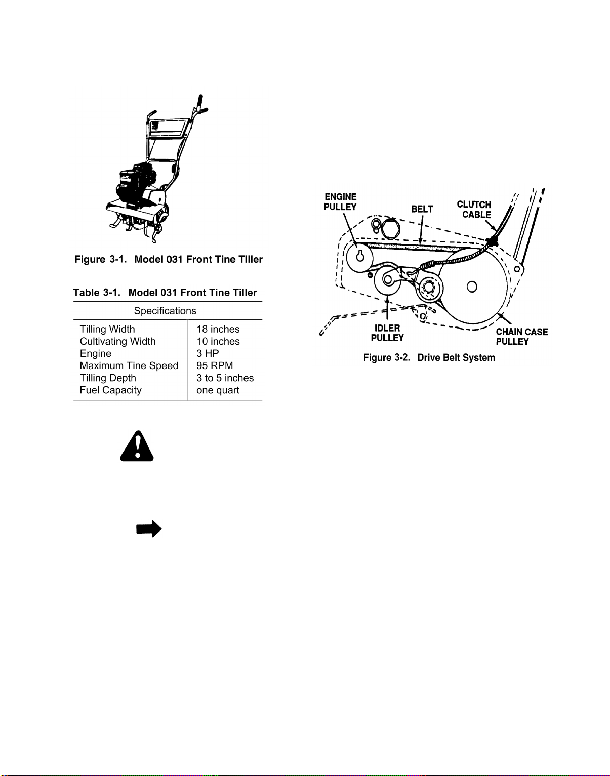
grease level. If the case is disassembled the
grease can be replaced. See Figure 3-1. For a
summary of specifications for Model 031, see
Table 3-1.
2. With clutch grip released (neutral position), pull
starter cord several times. The tines should not
turn. If they do, adjust the hex nuts at the
clutch cable bracket. Check again for correct
adjustment.
3-2.2 Clutch Adjustment.
Adjust clutch as follows:
3-2.3 Belt System.
1. The clutch idler disengages the belt when you
release the clutch control lever. This will disengage the tines and allow the tiller to be in a
neutral position. See Figure 3-2.
2. If the engine pulley is removed note how it is
assembled. The hub is to the inside. Check the
V-belt alignment between the engine pulley
and chain case pulley.
Note the following:
WARNING
Disconnect spark plug wire from spark plug
and ground it against engine block (secure in V
slot) before making any adjustments or performing maintenance.
NOTE
Do not overtighten control wire. Too much tension may cause it to break.
1. Hold the clutch grip so that the grip is down
against the handle. Adjust clutch control cable
so that the slack is taken out of the control
wire. Tighten two hex nuts at cable support
bracket. Control wire should now be straight.
3-2.4 Belt Removal and Replacement.
1. Remove belt cover assembly by removing one
hex nut and lock washer, one self-tapping
screw, one hex bolt, flat washer and hex nut
and one hex bolt and external lock washer.
2. Lift belt cover assembly off tiller. Be careful not
to bend or kink clutch cable.
3. Remove belt and position new belt on engine
pulley and chain case pulley. See Figure 3-2.
4. Upon reassembly of belt cover, place belt over
top of idler pulley and between engine pulley
and weld pin on belt cover assembly.
5. Fasten belt cover assembly in position. Secure
with the hardware removed in step 1.
3-2
Page 17
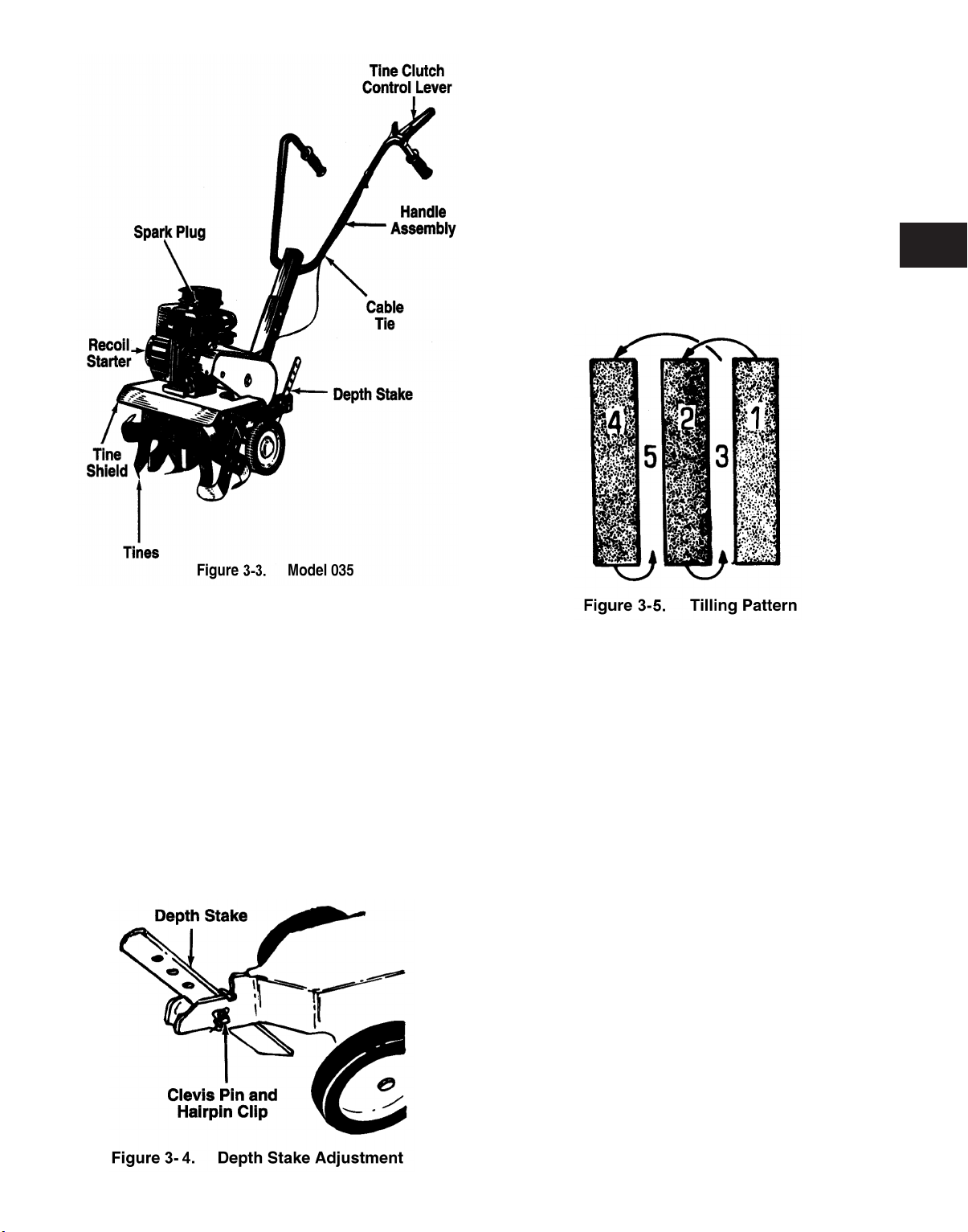
When tilling, leave approximately 8 inches of
untilled soil between the first and second tilling
paths, then make the third path between the
first and second as shown. In some soils, the
desired depth is obtained the first time over the
garden. In other soils, the desired depth is
obtained by going over the garden two or three
times. In the latter case, the depth stake
should be lowered before each succeeding
pass over the garden. Passes should be made
across the length and width of the garden alternately. Rocks which are turned up should be
removed from the garden area. See Figure 3-
5.
3
3-2A.1 CONTROLLING SPEED AND TILLING
DEPTH:
1. Depth Stake Adjustment: The depth stake acts
as a brake for the tiller and controls the depth
and speed at which the machine will operate.
Remove the clevis pin and hairpin clip to raise
or lower depth stake. See Figure 3-4.
By increasing the depth of the depth stake, the
forward speed of the machine is reduced, and
the working depth is increased. When the
depth stake is raised, the working depth of the
machine is reduced and the forward speed is
increased.
2. Handle Pressure: Further control of tilling
depth and travel speed can be obtained by
variation of pressure on the handles. A downward pressure on the handles will reduce the
working depth and increase the forward speed.
An upward pressure on the handles will
increase the working depth and reduce the forward speed. The type of soil and working conditions will determine the actual setting of the
depth stake and the handle pressure required.
3. Throttle Control: The throttle control lever
adjusts the engine speed and stops the
engine. With the throttle control pushed completely to the right, the carburetor is in START
or FAST position. Pulling the throttle back
reduces the engine speed to IDLE. Pull the
throttle completely back to stop the engine.
Use maximum engine speed for deep tilling.
Move the throttle control to IDLE when transporting the tiller.
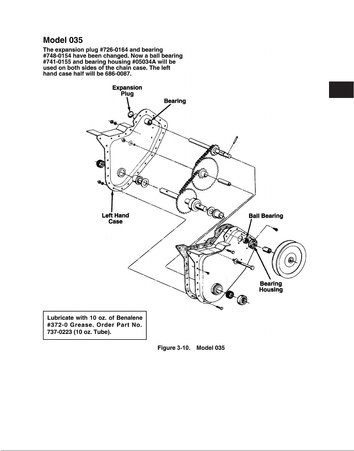
Model Series 035
3-2A.2 CULTIVATING
3-3
Page 18
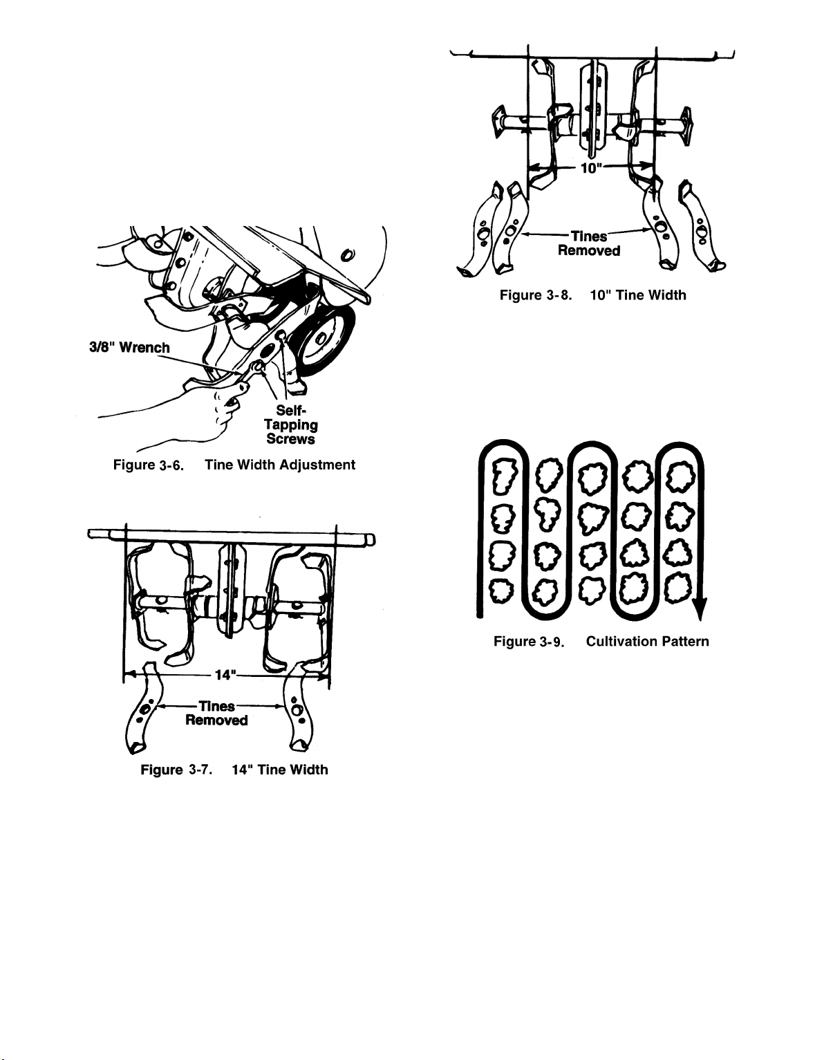
For cultivating, a two to three inch depth is
desirable. The throttle should be set to control
forward movement to a slow walking speed.
With the outer tines installed, the working width
of the machine is 18 inches. For cultivation,
this may be reduced to 14 inches by removing
the outer tines. Use a 3/8" wrench to remove
the two self-tapping screws on the outside of
the tines. Replace the first tine removed as
shown. See Figure 3-6.
When laying out plant rows, be sure to allow
enough width to permit cultivation between the
rows. In growing corn or similar crops, checkrow planting will permit cross cultivation and
practically eliminate hand hoeing. See Figure
3-9.
The minimum tilling width is 10 inches.
Remove both sets of outer tines by removing
the two self-tapping screws on the outside of
the tines. See Figure 3-8.
3-4
Chain Case
and sealed at the factory. It requires no checking unless the chain case is disassembled. To
fill with grease, lay the right half of the chain
case on its side. Add 10 ounces of Benalene
#372-0 grease and assemble the left half to the
right half.
—The chain case is pre-lubricated
Page 19
3
3-5
Page 20

3-6
Page 21
3-2.5 Disassembly of Tine Chain Case.
as follows:
1. Remove chain case from tiller.
2. Remove self-tapping screws, hex bolts, lock
washers and hex nuts from the outer edge of
chain case.
3. Remove hex bolt, lock washer and hex nut
from the center of chain case.
Proceed
6. Separate halves of the chain case housing. Be
careful not to damage the chain case gasket.
Replace if necessary.
NOTE
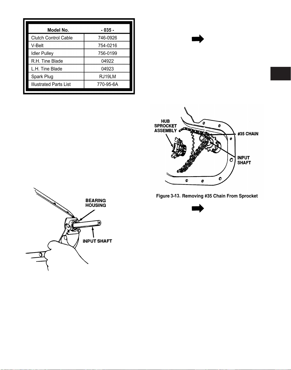
The drive system has 2 chain reduction steps.
Each step reduces the speed and increases
the torque or power down to the axle shaft. The
reduction is done with the use of a #35 chain to
a #420 chain.
7. Push input shaft inward slightly. Lift up on hub
sprocket assembly and remove the #35 chain
from the sprocket. See Figure 3-13.
3
4. Remove self-tapping screws from bearing
housing. See Figure 3-12.
Figure 3-12.
5. Slide bearing housing and bearing off input
shaft.
NOTE
This will allow slack in the other chain which
can be removed by lifting off the sprockets.
The hub sprocket assemblies will also be
removed from the housing during this procedure.
8. To disassemble the hub sprocket assembly,
slide the spacer out of the bearing. On an
arbor press place a spacer or similar tool on
the OD of the bearing and press bearing out of
hub sprocket assembly. See Figure 3-14.
3-7
Page 22

CAUTION
Both bearings must be pressed from the outside towards the center of housing. Pressure
should be exerted on the outer race or damage will result causing premature failure.
11. Inspection of Parts.
a. Inspect chains for breakage or bent clips
(master links).
b. Inspect sprockets and shafts for excessive
wear or breakage.
c. Inspect bearings on input and output
shafts for excessive wear.
9. To remove the tine shaft assembly simply pull
the complete assembly out of the housing. See
Figure 3-15.
NOTE
The chain case is lubricated with 10 ounces of
plastilube #0 grease to keep the bearings and
chains operating in a constant lubrication bath.
CAUTION
When reassembling, make certain the step
spacer and washer are positioned properly or
damage to the shaft assembly and/or bearings will result.
10. Remove bearings from the housing using an
arbor press. See Figure 3-16.
d. Inspect spacers and washers for exces-
sive wear.
3-2.6 Chain Case Seal and Bearing Replacement.
Proceed as follows:
WARNING
Disconnect spark plug wire and ground against
engine.
1. On a bench or suitable surface, block up the
chain case so that the tines clear the bench.
2. Remove the hardware which secures the tines
to the shaft and remove from unit.
3-8
Page 23
NOTE
The dust caps have a molded lip on the ID
which seats into a groove in the bearing hub
allowing for a tight fit.
3. Carefully pry off dust caps from housing
assembly.
5. Reattach bearing and bearing housing to tiller
housing with self-tapping screws removed in
step 3.
6. Reassemble pulleys, belt and belt guard
removed in step 2.
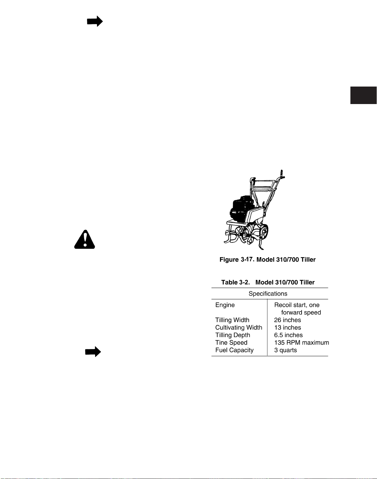
3-3. Model 310/700 Tiller.
4. Pry old seal out of housing assembly and slide
off shaft.
5. Remove any rust or foreign material from shaft
and thoroughly clean to avoid damage or contamination to seal or bearing.
6. Apply a generous amount of oil to shaft and
new seal and carefully slide seal into position.
Make certain the new seal is completely
seated against the shaft bearing.
7. Reassemble dust caps making certain they are
fully seated on the bearing hub.
8. Reattach the tines with the hardware removed
in step 3.
3-2.7 Input Shaft Bearing Replacement.
WARNING
Disconnect spark plug wire and ground it
against engine.
3-3.1 This tiller has forward speed only. There is no
reverse. The chain case has a two step reduction. The V-belt goes from a small engine pulley to a large input on the chain case. The
chain case is sealed at the factory and there is
no need to check or change the lubricant
unless the chain case has been disassembled
for repair. See Figure 3-17. For a summary of
specifications for Model 310/700, see Table 3-
2.
3
1. To replace bearing on tine chain case assembly, remove belt guard, belts and pulleys from
input shaft.
2. Remove self-tapping screws which secure
bearing housing to tiller housing.
3. Slide bearing housing and bearing off input
shaft.
NOTE
Pressure should be applied to the outer race of
the bearing and the housing should be secured
properly. Any force exerted on the inner race
will result in bearing damage or premature failure.
4. Press bearing out of housing and replace with
a new bearing.
3-3.2 The most common mistake made on any tiller
is assembling the tines backwards. THE
SHARP EDGE OF THE TINES MUST ENTER
THE SOIL FIRST.
3-9
Page 24

NOTE
The dust caps have a molded lip on the ID
which seats into a groove in the bearing hub
allowing for a tight fit.
3. Carefully pry off dust caps from housing
assembly.
5. Reattach bearing and bearing housing to tiller
housing with self-tapping screws removed in
step 3.
6. Reassemble pulleys, belt and belt guard
removed in step 2.
3-3. Model 310/700 Tiller.
4. Pry old seal out of housing assembly and slide
off shaft.
5. Remove any rust or foreign material from shaft
and thoroughly clean to avoid damage or contamination to seal or bearing.
6. Apply a generous amount of oil to shaft and
new seal and carefully slide seal into position.
Make certain the new seal is completely
seated against the shaft bearing.
7. Reassemble dust caps making certain they are
fully seated on the bearing hub.
8. Reattach the tines with the hardware removed
in step 3.
3-2.7 Input Shaft Bearing Replacement.
WARNING
Disconnect spark plug wire and ground it
against engine.
3-3.1 This tiller has forward speed only. There is no
reverse. The chain case has a two step reduction. The V-belt goes from a small engine pulley to a large input on the chain case. The
chain case is sealed at the factory and there is
no need to check or change the lubricant
unless the chain case has been disassembled
for repair. See Figure 3-17. For a summary of
specifications for Model 310/700, see Table 3-
2.
3
1. To replace bearing on tine chain case assembly, remove belt guard, belts and pulleys from
input shaft.
2. Remove self-tapping screws which secure
bearing housing to tiller housing.
3. Slide bearing housing and bearing off input
shaft.
NOTE
Pressure should be applied to the outer race of
the bearing and the housing should be secured
properly. Any force exerted on the inner race
will result in bearing damage or premature failure.
4. Press bearing out of housing and replace with
a new bearing.
3-3.2 The most common mistake made on any tiller
is assembling the tines backwards. THE
SHARP EDGE OF THE TINES MUST ENTER
THE SOIL FIRST.
3-9
Page 25
3-3.3 Clutch Adjustment.
2. After removing three screws, lift off belt cover.
WARNING
Disconnect spark plug wire and ground it
against engine before performing any adjustments, repairs or maintenance.
NOTE
Do not overtighten control wire. Too much tension may cause it to break.
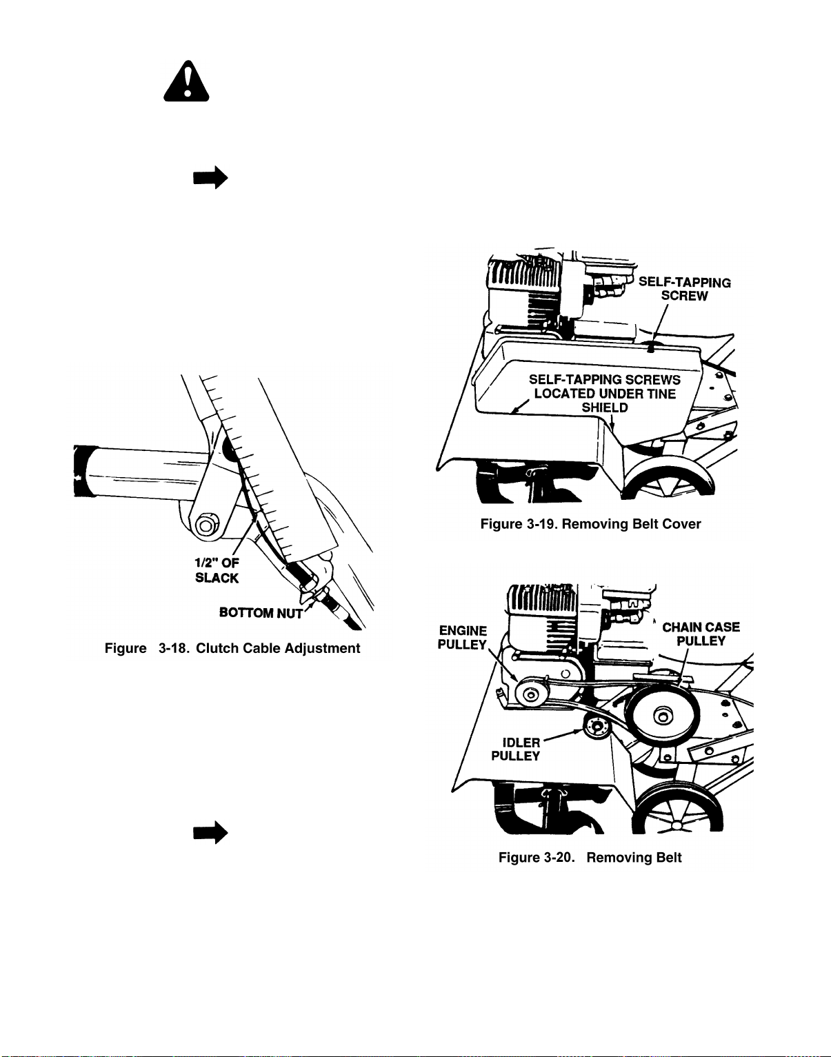
1. With clutch lever released (in up position),
adjust the bottom nut at the cable bracket so
there is 1/2 inch of slack in the control wire.
See Figure 3-18. Tighten upper nut against
bracket. Squeeze clutch lever against handle.
The control wire should now be straight.
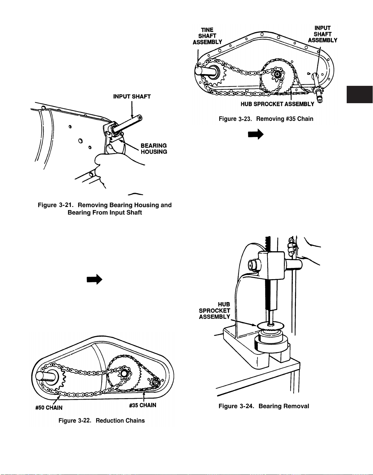
3. Slip belt off chain case pulley first then off idler
pulley. Remove belt from engine pulley. See
Figure 3-20.
4. To reassemble new belt, first place belt over
engine pulley. Be sure belt is inside two pins at
engine pulley.
5. Belt must be over top of idler pulley. Slip end of
belt over chain case pulley.
2. Secure end of spark plug wire in the V slot on
the engine. With clutch grip released (neutral
position), pull starter cord several times. The
tines should not turn. If they do, adjust hex
nuts at clutch cable bracket. Check again for
correct adjustment.
3-3.4 Belt Removal and Replacement.
NOTE
Your tiller has been engineered with a belt
made of special material (Kevlar Tensile). It
should not be replaced with an off-the-shelf
belt.
1. Remove the belt cover by removing three selftapping screws. A 3/8 inch wrench is required.
See Figure 3-19.
6. Reassemble belt cover.
3-3.5 Disassembly of Tine Chain Case.
1. Remove chain case from tiller.
3-10
Page 26
2. Remove self-tapping screws, hex bolts, lock
washers and hex nuts from the outer edge of
chain case.
3. Remove hex bolt, lock washer and hex nut
from the center of chain case.
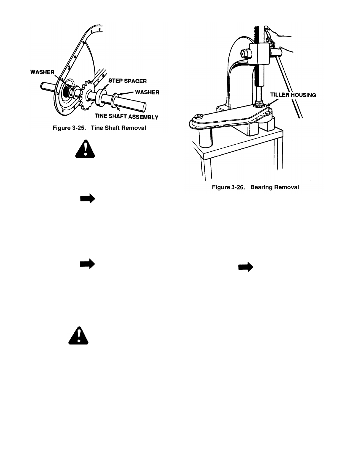
4. Remove self-tapping screws from bearing
housing. See Figure 3-21.
5. Slide bearing housing and bearing off the input
shaft.
3
NOTE
This will allow slack in the other chain which
can be removed by lifting off the sprockets.
The hub sprocket assemblies will also be
removed from the housing during this procedure.
8. To disassemble hub sprocket assembly, slide
spacer out of bearing. On an arbor press
remove bearing by placing a spacer or similar
tool on the OD of bearing and press out. See
Figure 3-24.
6. Separate the halves of the chain case housing.
Be careful not to damage chain case gasket.
Replace if necessary.
NOTE
The drive system has 2 chain reduction steps.
Each step reduces the speed and increases
the torque or power down to the axle shaft. The
reduction is done with the use of a #35 chain to
a #50 chain. See Figure 3-22.
7. Push input shaft inward slightly. Lift up on hub
sprocket assembly and remove #35 chain from
the sprocket. See Figure 3-23.
9. To remove tine shaft assembly simply pull the
complete assembly out of the housing. See
Figure 3-25.
3-11
Page 27
CAUTION
When reassembling, make certain the step
spacers and washers are positioned properly
or damage to the shaft assembly and/or bearings will result. (Cupped side faces sprocket.)
NOTE
The chain case is lubricated with 12 ounces of
plastilube #0 grease to keep the bearings and
chains operating in a constant lubrication bath.
10. Remove bearings from housing using an arbor
press. See Figure 3-26.
NOTE
Both bearings must be pressed from the outside towards the center of housing as shown.
Pressure should be exerted on the outer race
or damage will result causing premature failure.
3-3.6 Chain Case Seal and Bearing Replacement.
WARNING
Disconnect spark plug wire and ground it
against engine.
1. On a bench or suitable surface, block up chain
case so that tines/wheels clear the bench.
2. Remove the hardware which secures the tines
to shaft and remove from unit.
3. Carefully pry off dust caps from housing
assembly.
NOTE
The dust caps have a molded lip on the ID
which seats into a groove in the bearing hub
allowing for a tight fit.
4. Pry old seals out of housing assembly and
slide off shaft.
5. Remove any rust or foreign material from shaft
and thoroughly clean to avoid damage or contamination to seal.
6. Apply a generous amount of oil to shaft and
new seal and carefully slide seal into position.
Make certain new seal is completely seated
against shaft bearing.
3-12
7. Reassemble dust caps making certain they are
fully seated on the bearing hub.
Page 28
8. Reattach tines/wheels with the hardware
removed in step 3.
3-3.7 Input Shaft Bearing Replacement.
WARNING
Disconnect spark plug wire and ground it
against engine.
1. To replace bearing on tine chain case assembly, remove belt guard, belts and pulleys from
input shaft.
2. Remove self-tapping screws which secure
bearing housing to tiller housing.
3. Slide bearing housing and bearing off input
shaft.
4. Press bearing out of housing and replace with
a new bearing.
CAUTION
Pressure should be applied to the outer race of
the bearings and the housing should be
secured properly. Any force exerted on the
inner race will result in bearing damage or premature failure.
5. Reattach bearing and bearing housing to tiller
housing with self-tapping screws removed in
step 3.
3
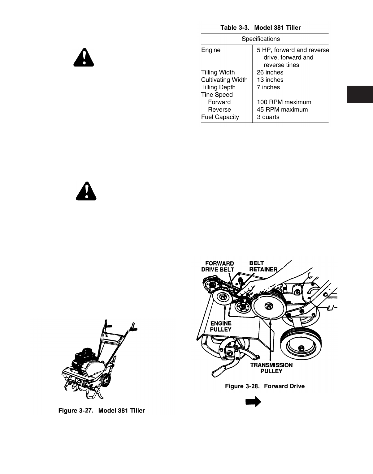
3-4.1 Forward Drive Belt Removal and Replace-
ment.
1. Remove belt guard by removing four hex selftapping screws.
2. Press down on left side of tine shield and slip
off belt guard.
3. Remove forward drive belt from beneath belt
retainer.
4. Roll belt off transmission pulley.
5. Remove belt from around engine pulley and lift
it off idler pulley. See Figure 3-28.
6. Reassemble pulleys, belt and belt guard
removed in step 2.
3-4. MODEL 381 TILLER. See Figure 3-27 and
Table 3-3.
NOTE
Make certain the forward drive belt is assembled with the wide side of the belt away from
transmission and engine pulleys.
3-13
Page 29

8. Reattach tines/wheels with the hardware
removed in step 3.
3-3.7 Input Shaft Bearing Replacement.
WARNING
Disconnect spark plug wire and ground it
against engine.
1. To replace bearing on tine chain case assembly, remove belt guard, belts and pulleys from
input shaft.
2. Remove self-tapping screws which secure
bearing housing to tiller housing.
3. Slide bearing housing and bearing off input
shaft.
4. Press bearing out of housing and replace with
a new bearing.
CAUTION
Pressure should be applied to the outer race of
the bearings and the housing should be
secured properly. Any force exerted on the
inner race will result in bearing damage or premature failure.
5. Reattach bearing and bearing housing to tiller
housing with self-tapping screws removed in
step 3.
3
3-4.1 Forward Drive Belt Removal and Replace-
ment.
1. Remove belt guard by removing four hex selftapping screws.
2. Press down on left side of tine shield and slip
off belt guard.
3. Remove forward drive belt from beneath belt
retainer.
4. Roll belt off transmission pulley.
5. Remove belt from around engine pulley and lift
it off idler pulley. See Figure 3-28.
6. Reassemble pulleys, belt and belt guard
removed in step 2.
3-4. MODEL 381 TILLER. See Figure 3-27 and
Table 3-3.
NOTE
Make certain the forward drive belt is assembled with the wide side of the belt away from
transmission and engine pulleys.
3-13
Page 30

6. Reassemble the new belt following instructions
in reverse order.
5. Reassemble new belt following instructions in
reverse order.
3-4.2 Reverse Drive Belt Removal and Replace-
ment.
1. To remove reverse drive belt, first remove forward drive belt as instructed in the previous
paragraph.
2. Remove reverse drive belt from beneath belt
retainer.
3. Roll belt off transmission pulley. Remove it
from beneath forward idler bracket. See Figure
3-29.
3-4.3 Disassembly of Tine Chain Case.
Disassemble as follows:
1. Remove chain case from tiller.
2. Remove self-tapping screws, hex bolts, lock
washers and hex nuts from the outer edge of
chain case.
3. Remove hex bolt, lock washers, and hex nut
from center of the chain case. See Figure 3-31.
4. Remove hex nut which secures reverse idler
pulley to idler bracket. Slide idler pulley out and
remove belt. See Figure 3-30.
NOTE
Make certain reverse drive belt is assembled
with the wide side of the belt against transmission and engine pulleys.
4. Remove self-tapping screws from bearing
housing. See Figure 3-32.
5. Slide bearing housing and bearing off input
shaft.
6. Separate the halves of chain case housing. Be
careful not to damage chain case gasket.
Replace if necessary. See Figure 3-33.
3-14
Page 31

NOTE
3
NOTE
The chain case is lubricated with 16 ounces of
plastilube #0 grease to keep the bearings and
chains operating in a constant lubrication bath.
The drive system has 3 chain reduction steps.
Each step reduces the speed and increases
the torque or power down to the axle shaft. The
reduction is done with the use of the #41 chain
to a #420 chain to a #50 chain.
7. Remove the middle #420 chain by lifting off
one end from sprocket bearing sleeve assembly and the other end from sprocket shaft. See
Figure 3-34.
9. To disassemble hub sprocket assemblies, slide
spacer out of bearing. On an arbor press
remove bearing by placing a spacer or similar
tool on the OD of bearing and press out. See
Figure 3-36.
8. Remove the second #50 chain from tine shaft.
The sprocket bearing sleeve assembly can
also be removed. See Figure 3-35.
3-15
10. To remove tine shaft assembly simply pull
complete assembly out of housing. See Figure
3-37.
Page 32

CAUTION
When reassembling, make certain the step
spacer and washer are positioned properly or
damage to the shaft assembly and/or bearings
will result. (Cupped side faces sprocket.)
11. Remove keyed input shaft from sprocket
sleeve assembly as shown. See Figure 3-38.
3-4.4 Chain Case Seal and Bearing
Replacement.
WARNING
Disconnect spark plug wire and ground it
against engine.
1. On a bench or suitable surface, block up chain
case so that the tines clear the bench.
2. Remove the hardware which secures tines to
shaft and remove from the unit.
NOTE
12. Remove the third #420 chain from sprocket
and sprocket shaft. The sprocket sleeve
assembly can also be removed.
CAUTION
Both bearings must be pressed from the outside towards the center of housing. Pressure
should be exerted on the outer race or damage will result causing premature failure.
13. Remove bearings from housing using an arbor
press. See Figure 3-39.
The dust caps have a molded lip on the ID
which seats into a groove in the bearing hub
allowing for a tight fit.
3. Carefully pry off dust caps from housing
assembly.
4. Pry old seals out of housing assembly and
slide off shaft.
5. Remove any rust or foreign material from shaft
and thoroughly clean to avoid damage or contamination to seal or bearing.
6. Apply a generous amount of oil to shaft and
new seal and carefully slide seal into position.
3-16
Page 33

Make certain new seal is completely seated
against shaft bearing.
7. Reassemble dust caps making certain they are
fully seated on bearing hub.
8. Reattach tines with the hardware removed in
step 3.
5. Reattach bearing and bearing housing to tiller
housing with self-tapping screws removed in
step 3.
6. Reassemble pulleys, belt and belt guard
removed in step 2.
3-5. Tiller Models 340 And 390.
3-4.5 Input Shaft Bearing Replacement.
WARNING
Disconnect spark plug wire and ground it
against engine.
1. To replace bearing on tine chain case assembly, remove belt guard, belts and pulleys from
input shaft.
2. Remove self-tapping screws which secure
bearing housing to tiller housing.
3. Slide bearing housing and bearing off input
shaft.
NOTE
Pressure should be applied to the outer race of
the bearing and the housing should be secured
properly. Any force exerted on the inner race
will result in bearing damage or premature failure.
4. Press bearing out of housing and replace with
a new bearing.
3-5.1 The design of these tillers is new in concept
due to the fact that the transmissions are
designed and manufactured for replacement
(complete only) and are not as repairable component. They are lubricated and sealed at the
factory. No further lubrication is required and
should, if not abused, provide years of problem
free service.
3-5.2 Tiller Model 340 is the same as Model 390
except that the 390 has a reverse control. It
has an additional belt, reverse assembly control cable and pulleys. See Figures 3-30, 3-31,
3-32 and Table 3-4.
CAUTION
This tiller has been engineered with a belt
made of special material (Kevlar Tensile) for
longer life and better performance. It should
not be replaced with an off-the-shelf belt. If belt
replacement is required, order belt or belts by
part number from your nearest authorized service dealer. Forward Drive Belt—Part No. 7540428, Reverse Drive Belt (Model 390 only)—
Part No. 754-0429.
3
3-17
Page 34

Make certain new seal is completely seated
against shaft bearing.
7. Reassemble dust caps making certain they are
fully seated on bearing hub.
8. Reattach tines with the hardware removed in
step 3.
5. Reattach bearing and bearing housing to tiller
housing with self-tapping screws removed in
step 3.
6. Reassemble pulleys, belt and belt guard
removed in step 2.
3-5. Tiller Models 340 And 390.
3-4.5 Input Shaft Bearing Replacement.
WARNING
Disconnect spark plug wire and ground it
against engine.
1. To replace bearing on tine chain case assembly, remove belt guard, belts and pulleys from
input shaft.
2. Remove self-tapping screws which secure
bearing housing to tiller housing.
3. Slide bearing housing and bearing off input
shaft.
NOTE
Pressure should be applied to the outer race of
the bearing and the housing should be secured
properly. Any force exerted on the inner race
will result in bearing damage or premature failure.
4. Press bearing out of housing and replace with
a new bearing.
3-5.1 The design of these tillers is new in concept
due to the fact that the transmissions are
designed and manufactured for replacement
(complete only) and are not as repairable component. They are lubricated and sealed at the
factory. No further lubrication is required and
should, if not abused, provide years of problem
free service.
3-5.2 Tiller Model 340 is the same as Model 390
except that the 390 has a reverse control. It
has an additional belt, reverse assembly control cable and pulleys. See Figures 3-30, 3-31,
3-32 and Table 3-4.
CAUTION
This tiller has been engineered with a belt
made of special material (Kevlar Tensile) for
longer life and better performance. It should
not be replaced with an off-the-shelf belt. If belt
replacement is required, order belt or belts by
part number from your nearest authorized service dealer. Forward Drive Belt—Part No. 7540428, Reverse Drive Belt (Model 390 only)—
Part No. 754-0429.
3
3-17
Page 35

3-18
Page 36

3
3-19
Page 37

DRIVE SYSTEM
THE 390 SERIES TILLER IS THE SAME AS THE 340
EXCEPT THAT IT HAS REVERSE DIRECTION ALSO.
THE REVERSE IS 104 RPM. THE TRANSMISSION ON
THE 340/390 IS NOT A REPAIRABLE COMPONENT BUT
IS EASILY REMOVED AND REPLACED SHOULD SERVICING BE REQUIRED.
3-20
Page 38

3-5.3 Tine Width Adjustment.
1. The tilling width before adjustment is 22
inches. See Figure 3-43.
3
NOTE
The forward clutch cable is the cable which is
attached closer to the rear of the tiller. If the
spring has come loose, reattach.
2. The tilling width can be increased to 24 inches
by removing the clevis pins and hairpin clips.
Sliding the outer tines out 1-inch and securing
in this position with clevis pins and hairpin
clips. See Figure 3-44.
3. For cultivation, reduce the tine width to 13
inches by removing the outer tines completely.
See Figure 3-45.
3-5.4 Forward Clutch Control Cable Attachment.
Attach the end of the forward cable to bracket
underneath handle assembly as follows:
1. Loosen hex nut on threaded rod near the end
of cable, and move it up the rod as far as it will
go.
2. Unthread rod from the rest of the cable. Hook
Z end of rod into bracket underneath handle
assembly.
CAUTION
Do not overtighten control cable. Too much
tension may cause it to break when engaged.
3. Thread rod back into cable until cable is
straight. Do not tighten it enough to put any
tension on spring.
4. Thread hex nut down against the end of cable
to lock rod in this position.
3-21
Page 39

3-5.5 Reverse Clutch Control Cable Attachment
(Model 390 only).
loose, attach the end of the reverse cable to
the reverse drive lever above the handle
assembly in the same manner as you attached
the forward cable.
The reverse clutch cable is the cable which is
attached closer to the front of the tiller.
If the spring has come
NOTE
3-5.6 Clutch Adjustment.
WARNING
Disconnect spark plug wire from spark plug to
prevent accidental starting. Secure the end of
spark plug wire in V slot on the engine.
1. Engage and release the forward drive clutch
lever, then the reverse drive clutch lever
(model 390 only). If an excessive noise is
heard when releasing either drive clutch lever,
the cable may be too loose. Adjust either the
forward or reverse clutch cable by loosening
the hex nut, threading the rod into the cable
one or two turns, then tightening the nut.
2. With the clutch(es) in neutral (levers released),
pull the starter rope several times. The tines
should not turn. If they turn forward, loosen hex
nut on forward drive cable (beneath the handle
assembly). Unthread rod from cable several
turns. Tighten hex nut and check again for correct adjustment. If the tines turn in reverse,
adjust the reverse cable (above the handle
panel) in the same manner. See Figure 3-46.
WARNING
Disconnect spark plug wire and ground it
against engine.
1. Remove two self-tapping screws and flat
washers from the front of belt cover. Remove
hex stop nut and flat washer from side of belt
cover. Remove belt cover. See Figure 3-47.
3-5.7 Reverse Drive Belt Removal and Replace-
ment (Model 390 only).
engineered with belts made of special material
(Kevlar Tensile). They should not be replaced
with an off-the-shelf belt. If belt replacement is
required, order belt or belts by part number.
Remove and replace reverse drive belt as follows:
This tiller has been
3-22
Page 40

2. Lift belt off transmission pulley and engine pulley.
3. Remove hex nut which secures reverse idler
pulley to idler bracket. Slide idler pulley out and
remove belt. See Figure 3-48.
out from between belt keepers. Remove belt.
See Figure 3-49.
3
4. Reassemble new belt following instructions in
reverse order. Make certain reverse drive belt
is assembled with the wide side of belt against
transmission and engine pulleys. Be certain to
adjust clutch control as instructed in the final
clutch adjustment section.
3-5.8 Forward Drive Belt Removal and
Replacement.
WARNING
Disconnect spark plug wire and ground it
against engine.
1. Remove belt cover as instructed in step 1 of
previous subsection.
2. To remove forward drive belt on 390 models,
first remove reverse drive belt as instructed
previously.
3. Remove belt from idler pulley and from around
chain case pulley.
5. Install new belt following instructions in reverse
order. Make certain forward drive belt is
assembled with the wide side of belt away from
transmission and engine pulleys. Be certain to
adjust clutch control as instructed in the final
clutch adjustment section.
NOTE
Upon reassembly, make certain the belt is
routed in between belt keepers at engine pulley and over idler pulley.
3-6. TILLER MODELS 402 AND 405. See Figure
3-50 and Table 3-5.
4. Using a 9/16 inch wrench, remove hex bolt
which secures engine pulley. Slide pulley half
3-23
Page 41

3-24
Page 42

1. Remove belt cover by removing four self-tapping screws. See Figure 3-51.
3
3-6.1 Belt Tension Adjustment for Drive and Tine
Clutches.
sion may be required due to normal stretch
and wear on the belt. Adjustment is needed if
the tines seem to hesitate while tilling, but the
engine maintains the same speed. Adjust as
follows:
1. Loosen hex nuts at cable bracket on handle.
Do not overtighten control wire. Too much tension may cause it to break.
2. With clutch lever released, adjust bottom nut
so that there is only a slight amount of slack in
control wire.
3. Tighten upper nut against bracket.
3-6.2 Removal and Replacement of Long Tine
Belt.
Periodic adjustment of the belt ten-
NOTE
NOTE
2. Lift belt from under flat idler pulley.
3. Remove wire belt guard. See Figure 3-52.
4. Loosen, but do not remove, hex bolts on rear
engine pulley. See Figure 3-53.
Your tiller has been engineered with belts
made of special material (Kevlar Tensile) for
longer life and better performance. They
should not be replaced with an off-the-shelf
belt.
3-25
Page 43

1. Remove belt cover by removing four self-tapping screws. See Figure 3-51.
3
3-6.1 Belt Tension Adjustment for Drive and Tine
Clutches.
sion may be required due to normal stretch
and wear on the belt. Adjustment is needed if
the tines seem to hesitate while tilling, but the
engine maintains the same speed. Adjust as
follows:
1. Loosen hex nuts at cable bracket on handle.
Do not overtighten control wire. Too much tension may cause it to break.
2. With clutch lever released, adjust bottom nut
so that there is only a slight amount of slack in
control wire.
3. Tighten upper nut against bracket.
3-6.2 Removal and Replacement of Long Tine
Belt.
Periodic adjustment of the belt ten-
NOTE
NOTE
2. Lift belt from under flat idler pulley.
3. Remove wire belt guard. See Figure 3-52.
4. Loosen, but do not remove, hex bolts on rear
engine pulley. See Figure 3-53.
Your tiller has been engineered with belts
made of special material (Kevlar Tensile) for
longer life and better performance. They
should not be replaced with an off-the-shelf
belt.
3-25
Page 44

5. Slip engine pulley out until belt can be
removed.
6. Install new belt.
3-6.3 Removal and Replacement of Short Drive
Belt.
1. Remove tine belt as instructed in previous
paragraph.
2. Remove hex bolt, lock washer and flat washer
from rear engine pulley. Slip rear engine pulley
off engine.
3. Loosen two set screws on front engine pulley.
See Figure 3-54.
NOTE
Do not lose square key on engine shaft.
4. Remove lock nut on V-idler pulley.
5. Slide front engine pulley and V-idler pulley out.
See Figure 3-55.
6. Remove belt and install new belt. Be sure belt
is routed around guide pins. See Figure 3-56.
NOTE
Belt must be between V-idler pulley and idler
bracket.
3-26
Page 45

NOTE
NOTE
Upon reassembly, refer to your owners guide
for correct assembly of wire belt guard for your
model tiller.
NOTE
If the V-idler or flat idler pulleys are removed
for any reason, be sure to install with hub side
against idler bracket. See Figure 3-57.
The drive system has three chain reduction
steps. Each step reduces the speed and
increases the torque or power down to the axle
shaft. The reduction is done with the use of a
#35 chain to a #420 chain and again to another
#420 chain.
3
NOTE
3-6.4 Disassembly of Wheel Chain Case.
semble as follows:
1. Remove chain case from tiller.
2. Remove self-tapping screws, two hex bolts,
lock washers and nuts from the outer edge of
the chain case.
3. Remove one hex bolt, lock washer and hex nut
from the center of chain case.
4. Remove remaining hex bolt, lock washer and
hex nut from the center of chain case.
5. Remove self-tapping screws from bearing
housing.
6. Slide bearing housing and bearing off input
shaft.
7. Separate halves of the chain case housing. Be
careful not to damage chain case gasket.
Replace if necessary. See Figure 3-58.
Disas-
The chain case is lubricated with 10 ounces of
plastilube #0 grease to keep the bearings and
chains operating in a constant lubrication bath.
8. Push input shaft inward slightly. Lift up on the
hub sprocket assembly and remove #35 chain
from sprocket. This will allow slack in the other
chains which can be removed by lifting off the
sprockets.
The hub sprocket assemblies can also be
removed from the housing during this procedure. See Figure 3-59.
9. To disassemble hub sprocket assemblies slide
spacer out of bearing. On an arbor press
remove bearing by placing a spacer or similar
tool on the OD of bearing and press out. See
Figure 3-60.
3-27
Page 46

CAUTION
When reassembling, make certain the step
spacer and washers are positioned properly or
damage to the shaft assembly and/or bearings will result. (Cupped side faces sprocket.)
11. Remove bearings from housing using an arbor
press as shown. See Figure 3-62.
10. To remove the wheel shaft assembly simply
pull the complete assembly out of the housing.
See Figure 3-61.
NOTE
Both bearings, one plastic and one bronze,
must be pressed from the outside towards the
center of the housing.
3-28
Page 47

3-6.5 Disassembly of Tine Chain Case.
ble as follows:
1. Remove chain case from tiller.
2. Remove self-tapping screws, hex bolts, lock
washers and hex nuts from the outer edge of
chain case.
3. Remove hex bolt, lock washer and hex nut
from the center of chain case.
4. Remove self-tapping screws from bearing
housing. See Figure 3-63.
Disassem-
NOTE
The chain case is lubricated with 12 ounces of
plastilube #0 grease to keep the bearings and
chains operating in a constant lubrication bath.
7. Push input shaft inward slightly. Lift up on hub
sprocket assembly and remove #35 chain from
sprocket. This will allow slack in the other
chain which can be removed by lifting off the
sprockets. The hub sprocket assemblies will
also be removed from the housing during this
procedure. See Figure 3-65.
3
5. Slide bearing housing and bearing off input
shaft.
6. Separate the halves of chain case housing to
obtain access to reduction chains. Be careful
not to damage chain case gasket. Replace if
necessary. See Figure 3-64.
NOTE
8. To disassemble hub sprocket assembly, slide
spacer out of bearing. On an arbor press
remove bearing by placing a spacer or similar
tool on the OD of bearing and press out. See
Figure 3-66.
The drive system has 2 chain reduction steps.
Each step reduces the speed and increases
the torque or power down to the axle shaft. The
reduction is done with the use of a #35 chain to
a #50 chain.
3-29
Page 48

9. To remove tine shaft assembly simply pull
complete assembly out of housing. See Figure
3-67.
CAUTION
Both bearings must be pressed from the outside towards the center of housing as shown.
Pressure should be exerted on the outer race
or damage will result causing premature failure.
3-6.6 Dust Cap Removal and Replacement.
WARNING
Disconnect spark plug wire and ground it
against engine.
1. On a bench or suitable surface, block up chain
case so that tines/wheels clear the bench.
2. Remove the hardware which secures tines/
wheels to shaft and remove from unit.
NOTE
CAUTION
When reassembling, make certain step spacers and washers are positioned properly or
damage to the shaft assembly and/or bearings
will result. (Cupped side faces sprocket.)
10. Remove bearings from housing using an arbor
press as shown. See Figure 3-68.
The dust caps have a molded lip on the ID
which seats into a groove in the bearing hub
allowing for a tight fit.
3. Carefully pry off dust caps from housing
assembly.
4. Pry old dust caps out of housing assembly and
slide off shaft.
5. Remove any rust or foreign material from shaft
and thoroughly clean to avoid damage or contamination to seal or bearing.
6. Apply a generous amount of oil to shaft and
new seal and carefully slide seal into position.
Make certain new seal is completely seated
against shaft bearing.
7. Reassemble dust caps making certain they are
fully seated on bearing hub.
8. Reattach tines/wheels with the hardware
removed in step 3.
NOTE
To replace the bearing on tine chain case
assembly, the belt guard, pulleys and side
plate must be removed.
3-6.7 Input Shaft Bearing Removal and Replace-
ment.
3-30
Page 49

WARNING
Disconnect spark plug wire and ground it
against engine.
1. Remove self-tapping screws which secure
bearing housing to tiller housing.
2. Slide bearing housing and bearing off input
shaft.
CAUTION
Pressure should be applied to the outer race of
bearing and the housing should be secured
properly. Any force exerted on the inner race
will result in bearing damage or premature failure.
3. Press bearing out of housing and replace with
a new bearing.
4. Reattach bearing and bearing housing to tiller
housing with self-tapping screws removed in
step 2.
1. Loosen hex nut at cable bracket on handle.
See Figure 3-70
3
CAUTION
Do not overtighten control wire. Too much tension may cause it to break.
5. Replace belt guard, pulleys and side plate if
applicable.
3-7. TILLER MODELS 403 AND 406 WITH
REVERSE DRIVE. See Figure 3-69.
3-7.1 This is a 4 HP reverse direction tine unit. This
section also covers the model 406 5 HP unit.
Product description is the same as the 402 and
405 units with the exception that the 403 and
406 units have reverse direction drive.
2. With the clutch lever released, adjust the bottom nut so that there is only a slight amount of
slack in the control wire.
3. Tighten upper nut against bracket.
3-7.3 Belt Removal and Replacement.
1. Remove belt cover by removing four self-tapping screws. See Figure 3-71.
3-7.2 Belt Tension Adjustment for Drive and Tine
Clutches. Periodic adjustment of belt tension
may be required due to normal stretch and
wear on belt. Adjustment is needed if tines
seem to hesitate while tilling, but the engine
maintains the same speed. Adjust as follows:
2. To remove tine belt, lift up on idler pulley and
slip belt off tine chain case pulley. Remove belt
from the two-step engine pulley. See Figure 3-
72.
3-31
Page 50

WARNING
Disconnect spark plug wire and ground it
against engine.
1. Remove self-tapping screws which secure
bearing housing to tiller housing.
2. Slide bearing housing and bearing off input
shaft.
CAUTION
Pressure should be applied to the outer race of
bearing and the housing should be secured
properly. Any force exerted on the inner race
will result in bearing damage or premature failure.
3. Press bearing out of housing and replace with
a new bearing.
4. Reattach bearing and bearing housing to tiller
housing with self-tapping screws removed in
step 2.
1. Loosen hex nut at cable bracket on handle.
See Figure 3-70
3
CAUTION
Do not overtighten control wire. Too much tension may cause it to break.
5. Replace belt guard, pulleys and side plate if
applicable.
3-7. TILLER MODELS 403 AND 406 WITH
REVERSE DRIVE. See Figure 3-69.
3-7.1 This is a 4 HP reverse direction tine unit. This
section also covers the model 406 5 HP unit.
Product description is the same as the 402 and
405 units with the exception that the 403 and
406 units have reverse direction drive.
2. With the clutch lever released, adjust the bottom nut so that there is only a slight amount of
slack in the control wire.
3. Tighten upper nut against bracket.
3-7.3 Belt Removal and Replacement.
1. Remove belt cover by removing four self-tapping screws. See Figure 3-71.
3-7.2 Belt Tension Adjustment for Drive and Tine
Clutches. Periodic adjustment of belt tension
may be required due to normal stretch and
wear on belt. Adjustment is needed if tines
seem to hesitate while tilling, but the engine
maintains the same speed. Adjust as follows:
2. To remove tine belt, lift up on idler pulley and
slip belt off tine chain case pulley. Remove belt
from the two-step engine pulley. See Figure 3-
72.
3-31
Page 51

3. To remove reverse drive belt, lift up on small
idler pulley. Slip belt off outside sheave of
wheel chain case pulley. Remove belt from
two-step engine pulley. See Figure 3-73.
6. Lift forward drive belt off forward engine pulley
and remove. See Figure 3-75.
NOTE
4. Loosen (do not remove) hex nut at the top of
wire belt keeper. See Figure 3-74.
5. Pull bottom of wire belt keeper out and then
upward, pivoting it away from the forward
engine pulley.
When reassembling belts, be certain belts are
routed around all belt keeper pins.
7. Reassemble new belts, following instructions
in reverse order. See Figure 3-76.
3-32
Page 52

3-7.4 Disassembly of Wheel Chain Case. Refer to
paragraph 3-6.4.
3
NOTE
If V-idler or flat idler pulleys are removed for
any reason, be sure to install with hub side
against idler bracket. See Figure 3-77.
3-7.5 Disassembly of Tine Chain Case. Refer to
paragraph 3-6.5.
3-7.6 Dust Cap Removal and Replacement. Refer
to paragraph 3-6.6.
3-33
Page 53

3-7.7 Input Shaft Bearing Removal and Replace-
ment. Refer to paragraph 3-6.7.
3-8. TILLER MODELS 410 AND 420 (Figure 3-
78).
3-34
Page 54

3-8.1 Belt Removal and Replacement.
NOTE
CAUTION
Do not use an off-the-shelf belt.
Your tiller has been engineered with a belt
made of special material (Kevlar Tensile) for
longer life and better performance. It should
not be replaced with an off-the-shelf belt.
If belt replacement is required, order belt or
belts by part number from your nearest authorized dealer. Part No. 754-0438—V Belt
1. Disconnect and ground the spark plug wire
against the engine.
2. Remove the belt cover from the left side of the
tiller as follows.
a. Remove two torx head screws from the top
of belt cover.
b. Remove two hex cap nuts and flat washers
from front side of the belt cover. Remove
hex nut and flat washer at the back of the
cover.
Upon reassembly, make certain the belt is
routed over the idler pulley and inside of belt
keepers at engine pulley. See Figure 3-79.
3-8.2 Attaching the Clutch Cable.
1. Route the clutch cable through the cable clip
underneath the handle. Remove one hex nut
from the threaded casing on the end of the
cable. See Figure 3-80.
3
3. Remove the belt keeper assembly located
behind the engine pulley by removing two hex
bolts and lock washers. See Figure 3-79.
4. Remove belt. Reassemble new belt, following
instructions in reverse order.
2. Slip the wire through the slot on the cable
bracket underneath the handle. Push the end
of the casing up through the cable bracket.
Rethread the hex nut on the end of the cable.
Do not tighten at this time.
3. Pull the cable upwards to obtain slack, and
hook the “Z” end of the cable into the bracket
on the clutch control (beneath the handle
panel) as shown in Figure 3-80 (from right to
left). Thread hex nut back onto the end of the
cable casing.
NOTE
Do not overtighten control wire. Too much tension may cause it to break.
3-8.3 Final Clutch Adjustment. IMPORTANT: Ser-
vice the engine with oil and gasoline before
checking this adjustment. Refer to the separate engine manual packed with your tiller.
1. Position the tiller so the front counterweight is
against a solid object, such as a wall. With the
3-35
Page 55

gear selection lever in NEUTRAL, start the
engine.
2. Standing on the right side of the tiller, visually
examine the belt (inside the belt cover). It
should not be turning. If the belt turns with the
unit in neutral, adjust by moving the hex nut
below the cable bracket down a few turns. See
Figure 3-80. Tighten the upper hex nut against
the bracket.
3. Now move the shift lever to FORWARD
(Wheels Forward) position. Carefully engage
the clutch by squeezing the clutch handle
against the handle. The wheels should spin.
4. If the wheels do not spin with the unit in forward, adjust by moving the hex nut which is
above the cable bracket up a few turns.
Tighten the bottom hex nut against the bracket.
See Figure 3-80. Recheck both adjustments,
and readjust as necessary.
3-8.4 Handle Adjustment (See Figure 3-81). The
handle may also be adjusted to the height
desired. Loosen the handle height adjustment
lock a few turns. Pivot handle up or down to
desired position. Tighten lock.
On Model 420, the handle may also be
adjusted to be in line with the tiller, or swung to
the left or right so the operator is not walking in
the freshly tilled soil. To adjust the handle position from side to side, pull the handle adjustment handle back, pivot the tiller handle to
desired position and release the handle.
3-8.5 Gear Selection Handle. The gear selection
handle is located on the front of the handle
assembly (right hand handle on Model 420). It
is used to select NEUTRAL, REVERSE, or one
of the FORWARD modes. Shift only with clutch
handle disengaged (released). Pull or push the
handle so that the indicator on top of the shift
cover points to the operating mode desired.
See Figure 3-81. (Rock unit if it is difficult to
shift.)
REVERSE—Reverse wheel drive only.
NEUTRAL—Transmission is in neutral.
FORWARD Modes:
Wheels Forward—Forward wheel drive
only.
Tines Reverse —Forward wheel drive and
reverse tine drive.
WARNING
Make certain unit is in NEUTRAL when starting the engine.
3-8.6 Chain Case Removal.
1. Remove the hairpin clip, rubber washer and
flat washer from the bottom of the gear shift
rod. Slide the rod out of the handle. See Figure
3-82.
3-36
Page 56

2. Remove the self-tapping screw and casing
clamp which holds the throttle cable to the
engine. Disconnect the throttle control cable
“Z” fitting from the throttle lever. See Figure 3-
83.
3
4. Remove belt from gear case pulley. (Not necessary to remove belt from engine.) Disconnect the clutch cable from idler bracket and
remove the gear case pulley. See Figure 3-85.
3. Remove the belt cover and shift cover as an
assembly. Remove the nuts from the belt cover
and the nut and bolt securing the shift cover
bracket to the gear case. See Figure 3-84.
3-37
Page 57

5. Remove bolts and nuts securing the LH and
RH tine shield brackets, located on inside front
of the tine shield. Remove the nuts and bolts
on top rear of chain case. Separate rear
assembly from case. Remove the tines. See
Figure 3-86.
7. Roll the case assembly back away from the
frame. Remove the reinforcement plate and
idler bracket, the shift bracket, tines and
wheels from the gear case. See Figure 3-88.
NOTE
During assembly, loosely replace all nuts and
bolts to ensure proper fit. With all fasteners in
place, tighten securely.
6. Remove the bolts and nuts at the front of the
gear case (two at top and three at front and
two on bottom). Separate case from frame.
See Figure 3-87.
NOTE
It is not necessary to remove the engine from
the frame to change a gear case.
After chain case repairs are completed or a
replacement case is procured, reassemble in
reverse order of steps above.
When installing the shift bracket, do not force
the bracket onto the shaft.
3-8.7 Disassembly and Reassembly.
1. Lay the transmission on its right side. Provide
support as needed. See Figure 3-89.
3-38
Page 58

2. Inspect and clean the tine shaft and wheel
shaft. Polish to remove any nicks or burrs. See
Figure 3-90.
3. Remove the 17—1/4-20 taptite screws. See
Figure 3-91.
5. Remove the reinforcement bracket and flat
washer. See Figure 3-93.
3
6. Remove the cover support. See Figure 3-94.
4. Remove the 7/16-14 hex nut and bell washer.
See Figure 3-92.
3-39
7. Remove the cover support brackets. See Figure 3-95.
8. Remove the cable support bracket. See Figure
3-96.
Page 59

9. Split the housing and remove the upper half by
sliding evenly over the wheel and tines shafts.
See Figure 3-97.
11. Remove the two washers and the 45 tooth
gear. See Figure 3-99.
12. Remove the sprocket assembly simultaneously with the tine shaft assembly and roller
chain. See FIgure 3-100.
10. Remove the gasket. See Figure 3-98.
NOTE
The welded side of the tine shaft sprocket is on
the bottom.
13. Remove the cup spacer and flat washer from
the tine shaft. See Figure 3-101.
3-40
Page 60

14. Remove the wheel shaft assembly, Part No.
611-0023, along with washer and spacer. See
Figure 3-102.
Units produced prior to mid-1994: If rear wheel
drive is periodically lacking, the large spacer,
Part No. 750-0987, should be installed. See
Figure 3-104.
3
17. Lift the drive shaft assembly until the shift fork
is removed from the clutch collar. See Figure
3-105.
15. Remove the washer, spacer, gear idler assembly, and spacer from the jackshaft. See Figure
3-103.
16. Lift the large spacer off the 10 tooth spur gear.
NOTE
18. Remove the complete drive shaft assembly,
Part No. 611-0015, along with chain and
sprocket. See Figure 3-106.
3-41
Page 61

19. Complete drive shaft chain and sprocket disassembled. See Figure 3-107.
20. Remove the shift fork retaining ring and
remove the shift fork from the housing. See
Figure 3-108.
jackshaft with the reverse gear and spacer in
place.
a. Slide the sprocket approximately halfway
down the spur gear with the chain already
around the drive shaft sprocket.
b. Feed the chain around the sprocket.
c. Install the drive shaft while turning it
slightly to align it with the reverse gears.
d. The shift forks must also be put into the
clutch collar as you install the drive shaft.
e. Do not force the shift forks into the collar.
This could cause the collar to break.
f. Install the spacer, gear idler assembly,
spacer and washer onto the jackshaft.
g. Install the spacer, washers and wheel shaft
assembly.
h. Install the flat washer and cup spacer over
the tine shaft hole.
NOTE
Remove remaining gears and spacers from the
jackshaft.
21. Clean grease and debris from both housings,
gears and assemblies.
22. Replace any worn or broken parts.
23. To remove jackshafts from housing, remove
the 7/16-14 lock nuts on the outside of the
housing.
24. For reassembly, reverse disassembly instructions.
i. With the welded side of the tine shaft
sprocket down, assemble the roller chain,
and sprocket assembly together and install
into the housing.
j. Install the 45 tooth gear and two washers.
k. Install the gasket.
l. Using two and one half 16 ounce tubes (40
ounces) of Shell Durina grease, Part No.
737- 0148, thoroughly coat all gear surfaces and chain.
m. Install the housing by sliding it evenly over
the wheel and tine shafts.
n. Install the cover support.
o. Install the cable support.
p. Install the 7/16-14 lock nuts. Torque to 12-
15 ft-lbs. Do not overtighten.
q. Install the flat washer and reinforcement
bracket.
r. Install the bell washer and 7/16-14 hex nut.
NOTE
When assembling the drive shaft and intermediate shaft chain, place the spur gear over the
s. Install the 17—1/4-20 taptite screws.
t. Bench test the chain case to ensure proper
engagement of all gears.
3-42
Page 62

3-9. TILLER MODELS 430 AND 447.
3-9.1 Dual direction rear tines make the Model 430
exceptionally versatile. For light tilling, set the
sixteen 13-inch diameter tines to turn forward.
When stability is required for heavier tilling, set
tines to turn in reverse direction. Powered by a
three-step gear reduction chain drive transmission, the reverse direction tines dig deep into
the soil, doing in one pass what other rear tine
tillers require several passes to complete. See
Figure 3-109 and Table 3-5.
3
3-43
Page 63

3.8.2 Clutch Adjustment.
WARNING
Disconnect spark plug wire and ground it
against engine before performing any adjustments, repairs or maintenance.
NOTE
Do not overtighten control wire. Too much tension may cause it to break.
1. With clutch lever released (in up position),
adjust the bottom nut at the cable bracket so
there is only a slight amount of slack in the
control wire. See Figure 3-110. Tighten upper
nut against bracket. Squeeze clutch lever
against handle. The control wire should now be
straight.
2. Secure end of spark plug wire in the V slot on
the engine. With clutch grip released (neutral
position), pull starter cord several times. The
tines should not turn. If they do, adjust hex
nuts at clutch cable bracket. Check again for
correct adjustment.
3-9.3 Belt Removal and Replacement.
WARNING
Disconnect spark plug wire and ground it
against engine.
1. Remove belt cover from the left side of tiller as
follows.
a. Remove two self-tapping screws and flat
washers from the top of belt cover.
b. Remove hex nut and flat washer from the
side of the belt cover.
c. Remove hex nut and flat washer at the bot-
tom of the front of cover. See Figure 3-111.
NOTE
Your tiller has been engineered with a belt
made of special material (Kevlar Tensile) for
longer life and better performance. It should
not be replaced with an off-the-shelf belt. If belt
replacement is required, order belt or belts by
part number from your nearest authorized
dealer. Part No. 754-0434, V belt, is new for
1995 and prior.
2. Remove hex bolt (belt keeper) located beneath
engine pulley.
3-44
Page 64

3. Remove belt. Reassemble new belt following
instructions in reverse order.
NOTE
Upon reassembly, make certain the belt is
routed over idler pulley and inside of belt keepers at engine pulley. See Figure 3-112.
3
2. Remove knobs from control rod and handle
adjustment rod. See Figure 3-114.
3-9.4 Disassembly of Tiller.
WARNING
Disconnect spark plug wire and ground it
against engine before performing any repairs.
1. Remove counterweight from the front of tiller
by removing two hex bolts, flat washers, 1/2
inch lock washers and hex nuts. See Figure 3-
113.
3. Remove cotter pin from the end of handle
adjustment rod at positioner bracket. Remove
handle adjustment rod. See Figure 3-115.
3-45
Page 65

4. Remove cotter pin from hooked end of control
rod at indicator bracket. See Figure 3-116.
5. Remove roll pin from indicator bracket. See
Figure 3-117.
6. Remove shift cover by removing two self-tapping screws and flat washers. See Figure 3-
118.
3-46
7. Cut the cable tie holding the throttle control
cable at shifting shaft in top of chain case. See
Figure 3-119.
Page 66

8. Remove belt cover from left side of tiller as follows. See Figure 3-120.
c. Remove hex nut and flat washer from weld
bolt at the bottom of the front of the belt
cover.
9. Remove hex lock nut from weld bolt on idler
bracket and unhook spring. See Figure 3-121.
3
10. Loosen bottom hex nut on drive cable and
remove drive cable from cable bracket. See
Figure 3-122.
a. Remove two self-tapping screws and flat
washers from the top of belt cover.
b. Remove hex nut and flat washer from hex
bolt which goes through the frame and
middle of the belt cover (head of bolt is
inside the frame rail on the other side of
the tiller). Two 9/16 inch wrenches are
required.
11. Remove throttle control cable from the engine
by removing self-tapping screw and casing
clamp. Unhook Z end of cable. See Figure 3-
123.
3-47
Page 67

12. Remove handle by removing handle adjustment crank and two belleville washers, hex nut
and hex bolt. See Figures 3-124 and 3-125.
13. Remove depth bar, by removing clevis pin and
hairpin cotter. See Figure 3-126.
14. Remove handle pivot and positioner bracket as
one assembly by removing four hex bolts, lock
washers and hex nuts. See Figure 3-127.
3-48
15. Remove tine shield by removing two hex bolts,
lock washers and hex nuts at the back of tine
shield. See Figure 3-128.
Page 68

16. Remove eight bolts, lock washers and hex
nuts at front bottom edge of tine shield and
reinforcement bracket. Lift off tine shield. See
Figure 3-129.
3
18. Remove drive belt by holding the belt tight
(close to the engine). Remove hex bolt, lock
washer, flat washer and spacer at engine pulley. Slide one half of split belt off. See Figure 3-
131.
17. Remove tine assemblies from tine shaft on
chain case by removing clevis pin and hairpin
cotters. Slide tine assemblies off tine shaft.
See Figure 3-130.
19. To remove engine from engine mounting rails,
remove four hex bolts, lock washers and hex
nuts. See Figure 3-132.
3-49
Page 69

20. Remove wheels from wheel shaft by removing
hex bolt and belleville washer. See Figure 3-
133.
22. Remove two tine shield mounting brackets
from chain case.
23. Remove belt cover mounting bracket from
chain case.
24. Remove two engine mounting rails from chain
case.
3-9.5 If you get a tiller that is hard to roll on a floor,
you can loosen the three jackshaft bolts and
roll the tiller back and forth to help align the
gears. Tighten nuts when finished. This also
will help shorten break in time for the chain
case.
3-9.6 Disassembly of Chain Case.
1. Remove twelve self-tapping screws from
around the outside edge of chain case. See
Figure 3-135.
21. Remove V-pulley by removing hex bolt and flat
washer. Hold pulley with belt. See Figure 3-
134.
3-50
Page 70

2. Remove three hex nuts and flat washers.
3. Remove two gear case brackets. See Figure
3-136.
NOTE
It is not necessary to remove dust covers or
bearing housing to gain access into chain
case.
4. Now the two chain case housings can be separated by using two screwdrivers to pry upward.
You may also need to tap on the tine shaft and
wheel shaft with a mallet.
5. Remove, clean and inspect gasket. Replace if
necessary. See Figure 3-137.
3
3-51
Page 71

7. Remove three spacers. See Figure 3-97.
8. Lift out spur gear from jackshaft. Clean and
inspect spur gear for any damage; replace if
necessary. See Figure 3-140.
NOTE
Carefully retain flat spacer washer on top of
the 30 and 44 tooth spur gear assembly. This
is necessary for proper gear spacing.
9. Lift out spur gear assembly #50 chain and tine
shaft assembly. Clean and inspect gears for
any damage. Replace if necessary.
10. Remove the 30 and 44 tooth spur gear and flat
washer. Clean and inspect gears for any damage. Replace if necessary.
11. Remove gear hub. See Figure 3-141.
12. Lift out wheel shaft assembly, 55 tooth spur
gear assembly and #420 chain. Clean and
inspect all parts for damage. Replace if necessary. See Figure 3-142.
3-52
13. Remove detent shaft assembly and 16 tooth
spur gear assembly. Clean and inspect parts
for damage. Replace if necessary. See Figure
3-143.
Page 72

14. Remove shifting bracket and spacer. See Figure 3-144.
NOTE
Hub side of spur gear goes up upon reassembly.
3
16. Remove flat washer, spacer, three flat washers
and three jackshafts from housing. See Figure
3-146.
NOTE
In 1989 and earlier production the shift bracket
could slide out. In 1990 and later production
there is a snap ring on the shifting bracket on
the outer side of the housing to help absorb
shock during shipping. This will help avoid
damage to the shifting bracket that would
cause loss of shifting capability.
15. Remove the 30 tooth spur. Clean and inspect
for damage. Replace if necessary. See Figure
3-145.
17. To reassemble chain case, reverse preceding
steps.
3-53
Page 73

450 SERIES DUAL DIRECTION REAR TINE TILLER
Removing the Tiller from the Carton
1. Remove the staples from the top of the carton
using a pair of pliers. See Figure 3-147.
2. Carefully slice the carton tape sealing the top of
the carton using a utility knife.
NOTE
There are many ways to remove the unit from
the carton. Perform this step in a manner that best
suits you, and make certain the control cable does
not get bent or kinked during removal. See Figure
3-149.
3. Grasp the top flaps of the carton and pivot them
outward.
4. Remove all loose components from the carton
and set them aside. See Figure 3-148.
5. Remove all packing materials.
7. Remove and read all of the manuals. See Figure 3-150.
8. Fill out the registration form.
9. Locate the model and serial label and record
this information in your owners manual and on
the registration form. See Figure 3-151.
6. Remove the tiller from the carton.
3-54
Page 74

3
Depth Stake Installation
1. Tilt the tiller forward and rest it on the front
counterweight.
2. Locate the depth stake and remove the “T”
knob, flat washer, and hex bolt from the depth
stake. See Figure 3-152.
3. Remove the clevis pin and hairpin from the
depth stake.
NOTE
Make certain the depth stake is inserted with
the “L” portion facing rearward.
5. Secure the depth stake to the depth stake
bracket using the clevis pin and hairpin
removed earlier.
NOTE
Insert the clevis pin from right to left, through
the second hole from the top of the depth
stake.
6. Insert the hex bolt from the left, through the top
hole of the depth stake, and secure it from the
right using the flat washer and “T” knob
removed earlier.
7. Slowly lower the tiller rearward until it is resting
on the depth stake.
Handle Installation
1. Remove both hex cap screws and flange lock
nuts from the handle brackets using two 1/2"
wrenches and two 9/16” wrenches. See Figure
3-154.
4. Raise the tine shield hinge flap and insert the
depth stake (from below) up through the rear of
the upper tine shield directly in front of the
spacer. See Figure 3-153.
3-55
Page 75

NOTE
DO NOT remove the lower rear hex cap screw
and flange lock nut securing the handle brackets and spacer.
2. Locate and align the lower handle assembly
mounting holes with the holes in the handle
brackets.
3. Secure the lower handle assembly to the handle brackets with the hex cap screws and
flange lock nuts removed earlier, using two
1/2" wrenches and two 9/16” wrenches.
NOTE
The smaller hex cap screw is inserted in the
front mounting hole.
Clutch Cable Installation
1. Route the clutch cable up the left side of the
handle assembly.
2. Loosen the jam nut securing the eyebolt to the
threaded cable end using a 7/32” wrench and a
3/8” wrench. See Figure 3-155.
3. Unscrew and remove the eyebolt from the
threaded cable end.
4. Slide the threaded cable end up through the
center of the upper handle assembly mounting
hole and snap the retainer in place. See Figure
3-156.
NOTE
Spread the outer retainer tabs using a small
flat-blade screwdriver.
3-56
5. Thread the eyebolt into the threaded cable end
several turns. See Figure 3-157.
Page 76

6. Secure the eyebolt to the clutch bail with the
cap screw, flat washers, and elastic lock nut
using a 7/16” socket and a 7/16” wrench.
NOTE
If the bail closes with no resistance and the
clutch cable does not straighten out, tighten
the threaded cable end two turns at a time until
the bail closes to the handle bar comfortably
with a slight amount of resistance.
8. Secure the eyebolt to the threaded cable end
with the jam nut loosened earlier using a 7/32”
wrench and a 3/8” wrench.
NOTE
DO NOT over tighten the clutch control cable
or damage may occur.
IMPORTANT: Make certain the Clutch Cable
Adjustment is performed prior to operating the
tiller.
Shift Control Rod Installation
3
7. Grasp the bail and slowly close it to the upper
handle bar assembly.
NOTE
If the bail has too much resistance and does
not want to close to the upper handle bar,
loosen the threaded cable end two turns at a
time until the bail closes to the handle bar comfortably with a slight amount of resistance. See
Figure 3-158.
1. Remove the hairpins from the ends of the shift
control rod.
2. Identify the long and short angled ends of the
shift control rod.
3. Make certain the rubber washer is in place on
each end.
4. Insert the short angled end of the shift control
rod through the indicator bracket and secure it
with the hairpin removed earlier. See Figure 3-
159.
3-57
5. Insert the long angled end of the shift control
rod through the gear selector handle and
Page 77

secure it with the hairpin removed earlier. See
Figure 3-160.
Neutral Clutch Cable Adjustment
IMPORTANT: Make certain the engine has
been serviced with oil and gasoline prior to
performing this adjustment. Refer to the separate engine manual.
NOTE
DO NOT place fingers under the belt cover.
5. The belt should not have any motion. If the belt
has motion, proceed to step 6. If the belt does
not have motion, perform the Primary Forward
Clutch Cable Adjustment Section.
6. If the belt has motion with the tiller in neutral,
and the engine running, loosen the jam nut
securing the eyebolt to the threaded cable end
using a 7/32” wrench and a 3/8” wrench. See
Figure 3-162.
1. Position the front counterweight up against a
solid object. See Figure 3-161.
2. Make certain the gear selector indicator
bracket is in the NEUTRAL position.
3. Start the engine.
7. Loosen the eyebolt two full rotations at a time,
checking the belt for motion.
8. When the proper adjustment has been
achieved, tighten the hex jam nut down securing the eyebolt to the threaded cable end using
a 7/32” and a 3/8” wrench.
Primary Forward Clutch Cable Adjustment
WARNING
Make certain the engine has been serviced
with oil and gasoline prior to performing this
adjustment. Refer to the separate engine manual.
1. Position the front counterweight up against a
solid object. See Figure 3-163.
4. Standing on the right side of the tiller, examine
the belt (inside the belt cover) for motion.
3-58
Page 78

2. Place the gear selector indicator bracket in the
Forward Wheel Drive position.
3. Standing behind the tiller, grasp the upper handle bar assembly with two hands.
1. Disconnect and ground the spark plug wire
against the engine.
2. Remove the hairpin and clevis pin securing the
left wheel assembly to the wheel shaft.
3. Slide the left wheel assembly away from the
belt cover.
NOTE
Do not remove the left wheel assembly.
4. Remove both torx screws securing the top of
the belt cover to the tiller casing using a male
T27 torx. See Figure 3-164.
3
4. Slowly engage the bail to the upper handle bar
assembly and make certain the drive wheels
are spinning.
5. If the wheels do not spin, loosen the hex jam
nut securing the eyebolt to the threaded clutch
cable end using a 7/32” and a 3/8” wrench.
6. Tighten the threaded cable end two complete
rotations at a time, checking the clutch bail
engagement for spinning tires.
7. When the proper adjustment has been
achieved, tighten the hex jam nut down securing the eyebolt to the threaded cable end using
a 7/32” wrench and a 3/8” wrench.
IMPORTANT: Perform the Neutral Clutch
Cable Adjustment section prior to operating the
tiller.
Secondary Forward Clutch Cable Adjustment
IMPORTANT: Perform the Primary Forward
Clutch Cable Adjustment section prior to performing this section.
5. Remove the acorn lock nut and flat washer
securing the side belt cover to the tiller casing
using a 7/16” socket.
6. Remove the hex screw securing the belt cover
to the engine mounting bracket using a 3/8”
socket.
7. Remove the belt cover from the tiller.
8. Remove the hex screw, lock washer, and flat
washer securing the input pulley to the input
shaft using a 7/16” socket. See Figure 3-165.
3-59
Page 79

9. Remove the input pulley from the input shaft.
10. Loosen the lower jam nut securing the
threaded clutch cable end to the tiller case
bracket using two 1/2" wrenches. See Figure
3-166.
ward Clutch Cable Adjustment section prior to
operating the tiller.
Idler Pulley Rod Adjustment
IMPORTANT: After the Primary and Secondary
Forward Clutch Cable Adjustment sections
have been performed, the belt may be excessively stretched. When the belt stretches, the
idler pulley rod may need to be adjusted. See
Figure 3-167.
11. Rotate the lower hex nut until it is flush with the
threaded clutch cable end and tighten the upper
jam nut to the bracket.
12. Secure the upper jam nut to the tiller case
bracket using two 1/2" wrenches.
13. Assemble the input pulley and the belt cover to
the tiller in the reverse order above.
IMPORTANT: Perform the Neutral Clutch
Cable Adjustment section and the Primary For-
1. Make certain the engine is off and the clutch
bail is released.
2. Shift the gear selector to all the forward
modes.
NOTE
If the indicator bracket touches the idler pulley
rod (with the clutch control bail disengaged),
perform the following steps:
3. Disconnect and ground the spark plug wire
against the engine.
4. Remove the hairpin and clevis pin securing the
left wheel assembly to the wheel shaft.
5. Slide the left wheel assembly away from the
belt cover.
6. Remove both torx screws securing the top of
the belt cover to the tiller casing using a male
T27 torx. See Figure 3-168.
3-60
Page 80

7. Remove the acorn lock nut and flat washer
securing the side belt cover to the tiller casing
using a 7/16” socket.
8. Remove the hex screw securing the belt cover
to the engine mounting bracket using a 3/8”
socket.
13. Shift the gear selector to all the forward
modes.
14. Assemble the tiller in the reverse order above.
Tire Pressure
1. Remove the valve stem cap. See Figure 3-
170.
3
9. Remove the belt cover from the tiller.
10. Remove the hairpin and wave washer securing
the idler pulley rod to the idler bracket using a
pair of needle-nose pliers. See Figure 3-169.
11. Move the idler pulley rod to the lower hole in
the idler bracket.
2. Place a tire gauge over the end of the valve
stem and push down.
3. Record the pressure (P.S.I.).
4. Examine the side walls of the tire and identify
the manufacturer’s recommended pressure.
5. Inflate or deflate the tires until the recommended tire pressure has been achieved.
NOTE
Recommended tire pressure for this tiller is 20
P.S.I.
Gear Selector Positions
The shift selector handle is mounted left of
center on the upper handle bar.
a. By applying pressure to the shift selector han-
dle, the shift rod rotates the indicator bracket,
thus selecting a geared position in the transmission. See Figure 3-171.
12. Secure the idler pulley rod to the idler bracket
with the wave washer and hairpin removed
earlier.
3-61
Page 81

b. The shift cover label clearly states the gear the
tiller is in, and what direction the tines will
rotate. See Table 3-6 below.
1. The tilling depth is controlled by the depth
stake that can be adjusted to five different settings.
NOTE
Never engage the clutch bail while shifting.
Depth Stake and Side Shield Positions
WARNING
When operating the tiller for the firsttime, use
the depth stake setting that gives 1 inch of tilling depth (second hole from top). See Figure
3-172.
NOTE
The side shields must be adjusted along with
the depth stake. See Figure 3-173.
2. To adjust the depth stake, remove the hairpin
and clevis pin.
3. Move the depth stake up or down to the
desired height and secure it into place.
3-62
4. To adjust the side shields, remove the front
wing nut and loosen the rear wing nut.
5. Pivot the side shields to the desired position and
secure the wing nuts.
Page 82

6. When breaking up sod and performing shallow
cultivation, use the setting which gives 1” of tilling depth (second hole from the top).
NOTE
Make certain the side shields are lowered to
the lowest setting.
7. To increase depth, raise the depth stake and
side shields.
8. When tilling loose soil, the depth stake can be
raised to its highest position (bottom adjustment hole).
NOTE
3
Make certain both side shields are raised to
the highest setting.
9. When transporting the tiller, lower the depth
stake and secure it in the top adjustment hole.
Belt Replacement
IMPORTANT: This tiller has been engineered
to use a belt made of Kevlar Tensile for longer
life and better performance. The proper part
number belt for this tiller is Part No. 754-0434.
1. Disconnect and ground the spark plug wire
against the engine.
2. Remove the hairpin and clevis pin securing the
left wheel assembly to the wheel shaft.
3. Slide the left wheel assembly away from the
belt cover.
4. Remove both torx screws securing the top of
the belt cover to the tiller casing using a male
T27 torx. See Figure 3-174.
5. Remove the acorn lock nut and flat washer
securing the side belt cover to the tiller casing
using a 7/16” socket.
6. Remove the hex screw securing the belt cover
to the engine mounting bracket using a 3/8”
socket.
7. Remove the belt cover from the tiller.
8. Remove both hex screws and washers securing the belt keeper bracket to the engine using
a 1/2" socket. See Figure 3-175.
3-63
Page 83

9. Loosen the center lock jam nut and hex cap
screw securing the idler belt keeper to the idler
pulley.
10. Remove the V-belt from the unit.
11. Install a new belt in the reverse order above.
NOTE
Make certain the V-belt is installed properly
between the pulleys and the belt keepers.
12. Perform all Clutch Cable Adjustments prior to
operating the tiller.
Problem Solving Pathfinder
Problem: Wheels Do Not Rotate Under Power
Exterior Gear Case Assembly Inspection
1. Are the hairpins and clevis pins securing the
wheel assemblies to the wheel shafts? See
Figure 3-176.
a. Fix: Proceed to the Interior Gear Case Assem-
bly Inspection.
3. Is the spiral pin securing the indicator bracket
to the shift lever? See Figure 3-178.
a. Fix: Install hairpins and clevis pins.
2. Does the shift lever lock into each gear selection? See Figure 3-177.
a. Fix: Install a new spiral pin.
4. Is the clutch control cable adjusted properly?
See Figure 3-179.
3-64
Page 84

a. Fix: Perform the Clutch Cable Adjustment sec-
tions.
5. Is the V-belt worn or stretched? See Figure 3-
180.
8. Is the input pulley secured to the input shaft?
See Figure 3-181.
3
a. Fix: Secure the input pulley using a hex bolt,
lock washer, and flat washer.
9. Does the input pulley rotate the input shaft?
See Figure 3-182.
a. Fix: Perform the Belt Replacement section.
6. Is the V-belt routed correctly?
a. Fix: Remove the belt cover and verify that the
V-belt is routed correctly.
7. Does the engine pulley rotate the crankshaft of
the engine?
a. Fix: Remove the engine pulley halves and
replace.
a. Fix: Remove the input pulley and inspect the
engagement splines. If worn, replace the input
pulley.
10. When the indicator bracket is locked into a
wheel drive position, and the input pulley is
rotated, does the wheel shaft assembly rotate?
See Figure 3-183.
3-65
Page 85

a. Fix: Replace the snap ring and run through all
the gear selector positions. Test the unit in normal
11. With the spring pin and indicator bracket
removed, does the shift lever have a snap ring
securing it in place? See Figure 3-184.
Interior Gear Case Assembly Inspection
NOTE
Perform the Tiller Gear Case Assembly
Removal and the Gear Case Separation sections prior to performing the interior inspection.
1. Inspect the “L” portion of the shift lever where it
engages into the shift fork. See Figure 3-185.
CAUTION
Internal damage may have occurred to the
shift lever because of the missing snap ring. If
damaged, proceed to the Interior Gear Case
Assembly Inspection section.
a. Fix: Replace the snap ring and run through all
the gear selector positions. Test the unit in normal operating conditions to make certain internal damage did not occur. If damage, proceed
to the Interior Gear Case Assembly Inspection
section.
2. Is the “L” portion of the shift lever bent and not
allowing the shift fork to move through all
detent positions?
a. Fix: Proceed to the Shift Lever Replacement
section.
REVERSE WHEELS:
1. Using a drift punch, rotate the shift lever to the
reverse drive position (all the way down). See
Figure 3-186.
3-66
Page 86

NOTE
9. Does the 30T spur gear rotate the 11T inner
gear assembly?
The detent shaft must be held in place to move
the shift fork.
2. Slowly rotate the hexed input shaft counterclockwise and inspect the following functions:
NOTE
Replace any of the following components that
are found to be worn or damaged.
3. Does the 16T spur gear rotate with the hexed
input shaft?
4. Does the 16T spur gear or hexed input shaft
have extensive wear or damage?
5. Does the 16T spur gear rotate the 30T reverse
idler spur gear on the reverse jack shaft? See
Figure 3-187.
10. Does the 11T inner gear assembly have extensive wear or damage?
11. Does the 11T inner gear assembly rotate the
44T spur gear on the wheel reduction jack
shaft.
12. Does the 44T spur gear have extensive wear
or damage?
13. Does the 44T spur gear rotate the 10T wheel
input sprocket assembly? See Figure 3-188.
3
6. Does the 30T reverse idler spur gear have
extensive wear or damage?
7. Does the 30T reverse idler spur gear rotate the
30T spur gear on the center jack shaft?
8. Does the 30T spur gear have extensive wear
or damage?
14. Does the 10T wheel input sprocket assembly
have extensive wear or damage?
NOTE
This is a gear and sprocket component.
15. Does the wheel input sprocket assembly rotate
the #420 chain?
16. Does the #420 chain have extensive wear or
damage?
17. Does the #420 chain rotate the 33T wheel
shaft assembly? See Figure 3-189.
3-67
Page 87

18. Does the 33T wheel shaft assembly have
extensive wear or damage?
19. Does the weld securing the 33T gear to the
wheel shaft assembly appear to have any
defects? See Figure 3-190.
NOTE
The detent shaft must be held in place to move
the shift fork.
2. Slowly rotate the hexed input shaft counterclockwise and inspect the following functions:
NOTE
Replace any of the following components that
are found to be worn or damaged.
3. Does the 16T spur gear rotate with the hexed
input shaft?
4. Does the 16T spur gear or hexed input shaft
have extensive wear or damage?
5. Does the 16T spur gear rotate the lower 44T
spur gear on the center jack shaft?
6. Does the 44T spur gear have extensive wear
or damage?
FORWARD WHEELS:
1. Using a drift punch, rotate the shift lever to the
forward drive position (first position up past
neutral). See Figure 3-191.
7. Does the 44T spur gear rotate the 11T inner
gear assembly?
8. Does the 11T inner gear assembly have extensive wear or damage?
9. Does the 11T inner gear assembly rotate the
44T spur gear on the wheel reduction jack
shaft? See Figure 3-192.
3-68
Page 88

10. Does the 44T spur gear have extensive wear
or damage?
11. Does the 44T spur gear rotate the 10T wheel
input sprocket assembly?
16. Does the 33T wheel shaft assembly have
extensive wear or damage?
17. Does the weld securing the 33T gear to the
wheel shaft assembly appear to be broken or
defective? See Figure 3-194.
3
12. Does the 10T wheel input sprocket assembly
have extensive wear or damage?
NOTE
This is a gear and sprocket component.
13. Does the 10T wheel input sprocket assembly
rotate the #420 chain?
14. Does the #420 chain have extensive wear or
damage?
15. Does the #420 chain rotate the 33T wheel
shaft assembly? See Figure 3-193.
Problem: Tines Do Not Rotate Under Power
Exterior Gear Case Assembly Inspection
1. Are the hairpins and clevis pins securing the
tine assemblies to the tine shaft? See Figure 3-
195.
3-69
a. Fix: Install the hairpins and clevis pins.
2. Does the shift lever lock into each gear selection? See Figure 3-196.
Page 89

a. Fix: Proceed to the Interior Gear Case Assem-
bly
a. Fix: Perform the Clutch Cable Adjustment sec-
tions.
3. Is the spiral pin securing the indicator bracket
to the shift lever? See Figure 3-197.
• Fix: Install a new spiral pin.
4. Is the clutch control cable adjusted properly?
See Figure 3-198.
5 Is the V-belt worn or stretched? See Figure 3-199.
a. Fix: Perform the Belt Replacement section.
6. Is the V-belt routed correctly?
Fix: Remove the belt cover and verify that the
V-belt is routed correctly.
3-70
7. Does the engine pulley rotate the crankshaft of
the engine?
a. Fix: Remove the engine pulley halves and
replace.
8. Is the input pulley secured to the input shaft?
See Figure 3-200.
Page 90

3
a. Fix: Secure the input pulley using a hex bolt,
lock washer, and flat washer.
9. Does the input pulley rotate the input shaft?
See Figure 3-201.
a. Fix: Remove the input pulley and inspect the
engagement splines. If worn, replace the input
pulley.
a. Fix: Proceed to the Interior Gear Case Assem-
bly Inspection.
11. With the spring pin and indicator bracket
removed, does the shift lever have a snap ring
securing it in place? See Figure 3-203.
CAUTION
10. When the indicator bracket is locked into a
wheel drive and tine rotation position, and the
input pulley is rotated, does the tine shaft
assembly rotate with the drive shaft assembly?
See Figure 3-202.
Internal damage may have occurred to the
shift lever because of the missing snap ring.
a. Fix: Replace the snap ring and run through all
the gear selector positions. Test the unit in normal operating conditions, to make certain internal damage did not occur. If damaged, proceed to the Interior Gear Case Assembly
Inspection section.
Interior Gear Case Assembly Inspection
3-71
Page 91

NOTE
Perform the Tiller Gear Case Assembly
Removal and the Gear Case Separation sections prior to performing the interior inspection.
1. Inspect the “L” portion of the shift lever where it
engages into the shift fork. See Figure 3-204.
2. Is the “L” portion of the shift lever bent?
a. Fix: Proceed to the Shift Lever Replacement
section.
TINES REVERSE - Forward Drive
NOTE
Replace any of the following components that
are found to be worn or damaged.
3. Does the 16T spur gear rotate with the hexed
input shaft?
4. Does the 16T spur gear or hexed input shaft
have extensive wear or damage?
5. Does the 16T spur gear rotate the upper 44T
spur gear?
6. Does the 44T spur gear have excessive wear
or damage?
IMPORTANT: This section is specific to TINE
OPERATIONS, NOT wheel drive.
1. Using a drift punch, rotate the shift lever to the
tines reverse - forward wheel drive position
(both 44T spur gears on center jack shaft
engaged into 16T input spur gear). See Figure
3-204.
7. Does the 44T spur gear rotate the 9T tine input
sprocket assembly? See Figure 3-205.
8. Does the 9T tine input sprocket assembly have
excessive wear or damage?
NOTE
NOTE
The detent shaft must be held in place to move
the shift fork.
2. Slowly rotate the hexed input shaft counterclockwise and inspect the following functions:
This is a gear and sprocket component.
9. Does the 9T tine input sprocket assembly
rotate the #50 chain?
10. Does the #50 chain have extensive wear or
damage?
3-72
Page 92

11. Does the #50 chain rotate the 18T tine shaft
assembly? See Figure 3-206.
3
NOTE
12. Does the 18T tine shaft assembly have extensive wear or damage?
13. Does the weld securing the 18T gear to the
tine shaft assembly appear to be broken or
defective? See Figure 3-207.
TINES FORWARD - Forward Drive
IMPORTANT: This section is specific to TINE
OPERATIONS, NOT wheel drive.
1. Using a drift punch, rotate the shift lever to the
tines forward wheel drive position (all the way
up). See Figure 3-208.
The detent shaft must be held in place to move
the shift fork.
2. Slowly rotate the hexed input shaft counterclockwise and inspect the following functions:
NOTE
Replace any of the following components that
are found to be worn or damaged.
3. Does the 16T spur gear rotate with the hexed
input shaft?
4. Does the 16T spur gear or hexed input shaft
have extensive wear or damage?
5. Does the 16T spur gear rotate the wide 30T
forward tine idler gear assembly?
6. Does the wide 30T idler gear assembly have
extensive wear or damage?
7. Does the wide 30T idler gear assembly rotate
the 30T spur gear on the center jack shaft?
8. Does the 30T spur gear have extensive wear
or damage?
9. Does the 30T spur gear rotate the 9T tine input
sprocket assembly?
10. Does the 9T tine input sprocket assembly have
excessive wear or damage?
3-73
Page 93

11. Does the 9T tine input sprocket rotate the #50
chain? See Figure 3-209.
Problem: Tiller Will Not Go Into Neutral
12. Does the #50 chain have extensive wear or
damage?
13. Does the #50 chain rotate the 18T tine shaft
assembly? See Figure 3-210.
14. Does the 18T tine shaft assembly have extensive wear or damage?
15. Does the weld securing the 18T gear to the tine
shaft assembly appear to be broken or defective? See Figure 3-211.
Exterior Gear Case Assembly Inspection
1. Does the shift lever lock into each gear selection? See Figure 3-212.
a. Fix: Proceed to the Interior Gear Case Assem-
bly Inspection section.
2. Is the spiral pin securing the indicator bracket
to the shift lever? See Figure 3-213.
3-74
Page 94

3
a. Fix: Install a new spiral pin.
3. Is the V-belt too tight, binding up the input pulley?
a. Fix: Perform the Clutch Cable Adjustment sec-
tions.
4. Is the V-belt routed correctly? See Figure 3-
214.
a. Fix: Proceed to the Interior Gear Case Assem-
bly Inspection.
6. With the spring pin and indicator bracket
removed, does the shift lever have a snap ring
securing it in place? See Figure 3-216.
a. Fix: Remove the belt cover and verify that the
V-belt is routed correctly.
5. When the indicator bracket is locked into the
neutral drive position, and the input pulley is
rotated, does the drive shaft assembly rotate?
See Figure 3-215.
CAUTION
Internal damage may have occurred to the
shift lever because of the missing snap ring.
a. Fix: Replace the snap ring and run through all
the gear selector positions. Test the unit in normal operating conditions, to make certain internal damage did not occur. If damaged, proceed to the Interior Gear Case Assembly
Inspection section.
3-75
Page 95

Interior Gear Case Assembly Inspection
NOTE
Perform the Tiller Gear Case Assembly
Removal and the Gear Case Separation sections prior to performing the interior inspection.
1. Inspect the “L” portion of the shift lever where it
engages into the shift fork.
2. Is the “L” portion of the shift lever bent? See
Figure 3-217.
NOTE
The detent shaft must be held in place to move
the shift fork.
a. Fix: Proceed to the Shift Lever Replacement
section.
NEUTRAL
1. Using a drift punch, rotate the shift lever to the
neutral position (16T input spur gear not
engaged into any gears). See Figure 3-218.
2. Slowly rotate the hexed input shaft counterclockwise and inspect the following functions:
NOTE
Replace any of the following components that
are found to be worn or damaged.
1. Does the 16T spur gear rotate with the hexed
input shaft?
2. Does the 16T spur gear or hexed input shaft
have extensive wear or damage?
3. Does the shift lever move the shift fork and
16T input spur gear up and down the input
shaft freely?
Gear Case Removal
1. Support the front counterweight from below
using a suitable jack. See Figure 3-219.
3-76
Page 96

3
2. Remove both sets of hex nuts, lock washers,
and flat washers securing the front counterweight to the gear case assembly using a 3/4"
socket and a 3/4" wrench. See Figure 3-220.
3. Remove the front counterweight.
4. Remove the lock nut securing the idler pulley
assembly to the idler bracket using a 9/16”
socket and a 9/16” wrench. See Figure 3-221.
5. Remove the hex cap screw, flanged idler pulley, and idler belt keeper from the idler bracket.
6. Roll the V-belt off of the input pulley. See Figure 3-222.
7. Remove all three self tapping washer head
screws securing the engine to the gear case
assembly using a 1/2" socket. See Figure 3-
223.
3-77
Page 97

NOTE
Two self tapping screws on the right side and
one on the left.
8. Remove the hex bolt, bell washer, and hex nut
securing the left rear corner of the engine base
to the gear case assembly using a 1/2" socket
and a 1/2" wrench.
NOTE
11. Remove the spiral pin securing the indicator
bracket to the shift lever using a drift punch
and hammer. See Figure 3-225.
12. Remove both female torx screws securing the
shift cover to the gear case assembly using a
T27 torx.
13. Remove the clutch control cable from the eyebolt using a 7/32” wrench and a 3/8” wrench.
See Figure 3-226.
The left rear mounting hole is slotted for engine
alignment.
9. Remove both hairpins securing the ends of the
shift rod to the indicator bracket and shift lever
handle. See Figure 3-224.
14. Compress the snap retainer securing the
clutch control cable to the upper handle bar
and remove the cable using a pair of pliers.
See Figure 3-227.
10. Remove the shift rod.
3-78
Page 98

3
15. Remove and discard the zip tie securing the
clutch control cable to the lower handle bar.
16. Remove the T-knob, flat washer, and hex
screw from the depth stake. See Figure 3-228.
17. Remove the hairpin and clevis pin securing the
depth stake to the tine shield bracket.
NOTE
DO NOT remove the lower rear hex cap screw
and flange lock nut securing the handle brackets and spacer.
20. Remove the handle assembly from the unit.
21. Place chocks in front of the wheels to keep
them from rolling. See Figure 3-230.
18. Remove the depth stake.
19. Remove both hex cap screws and flange lock
nuts from the handle brackets using two 1/2"
wrenches and two 9/16” wrenches. See Figure
3-229.
22. Place the tiller in gear using a center drift
punch for leverage.
23. Tilt the tiller forward and place a jack-stand
under the center of the gear case assembly.
24. Remove the plastic wing nuts securing the side
tine shield covers and adjustable tine shields.
25. Remove the side tine shield covers and adjustable tine shields.
3-79
Page 99

26. Remove the clevis pins and hair pins securing
the right and left tine assemblies. See Figure
3-231.
27. Remove both tine assemblies from the tine
shaft assembly.
NOTE
The outer two hex bolts are shorter then the
middle two hex bolts.
29. Remove all four hex bolts securing the right
portion of the shoulder spacer bracket to the
tine shield and gear case assembly using a 1/
2" socket and a 1/2" wrench. See Figure 3-
233.
NOTE
Make certain the tine shaft is lubricated during
assembly.
28. Remove all four hex bolts securing the left portion of the shoulder spacer bracket to the tine
shield and gear case assembly using a 1/2"
socket and a 1/2" wrench. See Figure 3-232.
NOTE
The outer two hex bolts are shorter than the
middle two hex bolts.
30. Remove all four hex nuts, lock washers, and
carriage bolts securing the handle brackets to the
tine shield using a 9/16” socket. See Figure 3-
234.
3-80
Page 100

3
31. Remove the right rear hex bolt, flat washer,
and lock nut securing the rear tine shield to the
gear case assembly using a 1/2" socket and a
1/2" wrench. See Figure 3-235.
32. Remove the left rear hex bolt (rear shield stop),
flat washer, and lock nut securing the rear tine
shield to the gear case assembly using a 1/2"
socket and a 1/2" wrench. See Figure 3-236.
33. Remove the tine shield assembly from the
gear case assembly.
34. Remove both clevis pins and hair pins securing the wheel assemblies to the wheel shaft
assembly. See Figure 3-237.
NOTE
Lubricate the wheel shaft during assembly.
35. Remove both wheel assemblies.
36. Assemble the tiller in the reverse order above.
Gear Case Separation
1. Remove the hex screw, lock washer, and flat
washer securing the input pulley to the input
shaft using a 7/16” socket. See Figure 3-238.
3-81
 Loading...