

Page 1

Safety • Assembly • Operation • Adjustments • Maintenance •Troubleshooting • Parts Lists • Warranty
OPERATOR'S MANUAL
Zero Turn Riding Mower
Time Saver Models
i1046
i1050
IMPORTANT
READ SAFETY RULES AND INSTRUCTIONS CAREFULLY BEFORE OPERATION
Warning: Thisunit isequippedwithaninternalcombustionengineandshouldnot beusedon ornearanyunimprovedforest-covered,brush-
coveredor grass-coveredlandunlesstheengine'sexhaustsystemisequippedwitha sparkattestermeetingapplicablelocalor statelaws(if any),
If a sparkarresterisused,it shouldbemaintainedineffectiveworkingorderby theoperator,IntheStateof Californiathe aboveisrequiredbylaw
(Section4442ofthe CaliforniaPublicResourcesCode),Otherstatesmayhavesimilarlaws,Federallawsapplyonfederallands,Asparkattester
forthe mufflerisavailablethroughyour nearestengineauthorizedservicedealeror contacttheservicedepartment,P.O,Box361131Cleveland,
Ohio44136-0019,
CUB CADET LLC, P.O. BOX 361131 CLEVELAND, OHIO 44136-0019
PRINTEDIN U.S.A. 769-02708
09/2006
Page 2

This Operator's Manual is an important part of your new lawn mower. It will help you assemble,
prepare, and maintain the unit for best performance. Please read and understand what it says.
Table of Contents
Slope Gauge ............................................................... 3
Safe Operation Practices .......................................... 4
Setup and Adjustment .............................................. 8
Operating Your Lawn Mower ................................... 10
Making Adjustments .............................................. 17
Maintaining Your Lawn Mower ................................ 20
Off-Season Storage ................................................. 29
Optional Attachments ............................................ 29
Safety Labels .......................................................... 30
Troubleshooting ...................................................... 31
Replacement Parts ................................................. 33
Warranties ............................................................... 34
Recording Model Serial Number
BEFOREOPERATINGYOURNEWEQUIPMENT,pleaselocatethetractormodelplateandenginemodeplateon the equipmentandcopytheinforma-
tionto thesamplemodelplatesprovidedtothe below.Youcanlocatethe tractormodelplateeitherbeneaththeseatpivotplate,oronthefront/right
sideof theframe.Theengineidentificationislocatedon adecal(ordecals)affixedtotheengineshrouding.Thisinformationwill be necessarytouse
themanufacturer'swebsite,to obtainassistancefromthe CustomerSupportDepartment,or whencontactingan authorizedservicedealer.
KOHLER
IMPORTANT ENGINE INFORMATION
THIS ENGINE MEETS U.S. EPAAND CA2005 AND
LATERAND EC STAGE II(SN:4) EMISSION REGS
Model Number Serial Number
i_l, Lh_ CUB CADET LLC
www.cubcadet.¢om CLEVELAND, OH 44136
• DEALER L0CATOR PHONE NUMBER: 877-282-8684 j
P. O. BOX 361131
FOR SI SMALL OFF-ROAD ENGINES
FAMILY
TYPE APP
DISPL. (CC)
MODEL NO,
SPEC. NO,
SERIAL NO.
BUILD DATE
OEM PROD, NO.
EMISSION COMPLIANCE PERIOD:
EPA: CARB:
CERTIFIED ON:
REFER TO OWNER'S MANUAL FOR HP RATING,
SAFETY, MAINTENANCE AND/_JUSTMENTS
1-800-544-2444 w ww.kohlerengines.com
KOHLER CO. KOHLER, WISCONSIN USA
Customer Support
If youhavedifficultyoperatingthis productorhaveanyquestionsregardingthecontrols,operation,ormaintenanceof this unit,youcancontactthe
dealeryoupurchasedtheunit fromor choosefromtheoptionsbelow:
1. Visitwww.cubcadet.comformanyusefulsuggestions.Clickon
CustomerServiceor the ServiceLocatortofind thenearestCub
Cadetservicedealerin yourarea.
2. Toreachthe CustomerDealerReferralLine,pleasecall 1-877-282-
8684.
3. Theenginemanufacturerisresponsibleforall engine-relatedissues
withregardstoperformance,power-rating,specifications,warranty
andservice.Pleaserefertothe engineOwner's/Operator'sManualfor
moreinformation.
2
Page 3
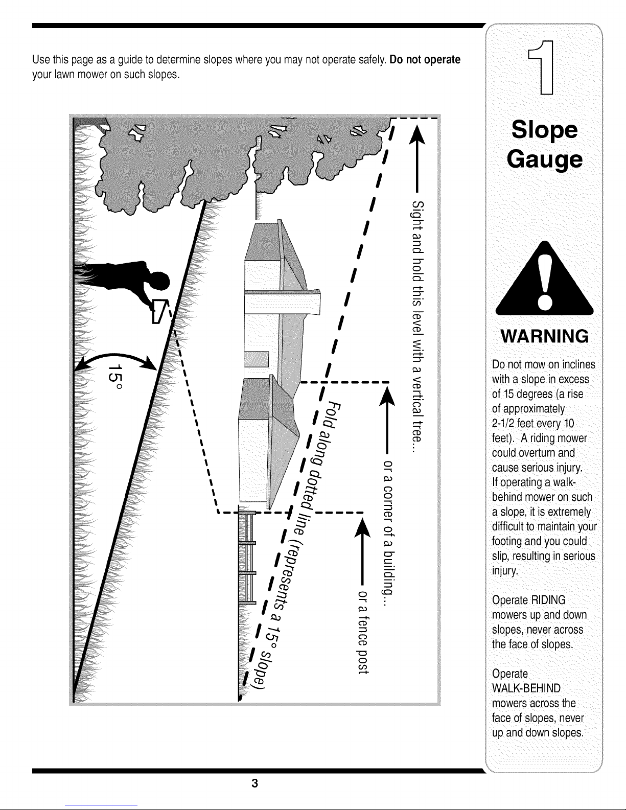
Usethis pageas a guide to determineslopeswhereyou may not operatesafely.Do not operate
your lawn mower on such slopes.
iI
iI
IIII
l
1
l
l
l
l
l
o
feet). A riding mower
couldoverturnand
cause serious injury.
If operatinga walk-
behindmower on such
a slope, it isextremely
difficult to maintainyour
footingand you could
slip, resulting inserious
injury.
Operate RIDING
mowersupand down
slopes, neveracross
the face of slopes.
S
Operate
WALK-BEHIND
mowersacrossthe
face of slopes, never
upand down slopes.
3
Page 4
WARNING: EngineExhaust,some of itsconstituents,andcertain vehicle compo-
nentscontain or emitchemicals knownto State of Californiato cause cancer and
birth defectsor otherreproductiveharm.
DANGER: This machinewas builtto beoperatedaccording to the rulesfor safe operation in this
manual.As with any type of power equipment,carelessnessor erroronthe part ofthe operator can
result inseriousinjury.This machine iscapableof amputatinghands andfeet andthrowing objects.
Failureto observethe followingsafety instructionscould resultin serious injury or death.
iCes
WARNING
Thissymbol points
outimportant safety
instructionswhich, if
notfollowed, could
i endangerthe personal
i safetyand/or property
ofyourselfand others.
Readand follow all
i instructionsinthis man-
ualbeforeattemptingto
operatethis machine.
Failureto compywith
these instructionsmay
resultin personalinjury.
Whenyou seethis
symbol.
HEED ITS WARNING
Your
i Responsibility
Restricttheuse
i of thispowermachine
to personswho read,
understand
I andfolFowthewarnings
and instructions
inthis manual
Children
1, Tragicaccidentscanoccuriftheoperatoris not
alertto thepresenceof children,Childrenareoften
attractedto themachineandthe mowingactivity,
Theydo notunderstandthedangers,Neverassume
thatchildrenwillremainwhereyoulastsawthem,
a, Keepchildrenoutofthe mowingareaandin
watchfulcare ofa responsibleadultotherthan
theoperator.
b, Bealertandturnmachineoff ifachildenters
thearea,
c, Beforeandwhilebacking,lookbehindand
downfor smallchildren,
d, Nevercarrychildren,evenwiththe blade(s)
shutoff,Theymayfalloffandbeseriously
injuredorinterferewithsafemachineoperation,
e, Useextremecarewhenapproachingblind
corners,doorways,shrubs,treesorother
objectsthatmayblockyourvisionofachild
whomayruninto themachine,
f, To avoid back-overaccidents, always
disengagethe cuttingblade(s) before
shiftinginto Reverse.If equipped,the
"Reverse Caution Mode"shouldnotbe
usedwhen childrenor others are around.
g, Keepchildrenawayfromhotor running
engines,Theycan sufferburnsfroma hot
muffler,
h, Removekeywhenmachineisunattendedto
preventunauthorizedoperation,
2, Neverallowchildrenunder14yearsoldto operate
themachine,Children14yearsoldandovershould
readand understandthe operationinstructionsand
safetyrulesinthis manualandshouldbetrainedand
supervisedbya parent,
Operation
Safe Handling of Gasoline:
1. Toavoid personal injury or property damageuse
extremecare in handling gasoline.Gasolineis
extremely flammableand the vaporsareexplo-
sive. Seriouspersonalinjurycanoccurwhengasoline
isspilledonyourselforyourclotheswhichcan ignite,
Washyourskinandchangeclothesimmediately,
a, Useonlyanapprovedgasolinecontainer,
b, Neverfillcontainersinsideavehicleor ona
truckor trailerbedwitha plasticliner.Always
placecontainersonthegroundawayfrom
yourvehiclebeforefilling,
c, Whenpractical,removegas-powered
equipmentfromthe truckor trailerand refuelit
ontheground,Ifthis isnotpossible,then
refuelsuchequipmenton a trailerwitha
portablecontainer,ratherthanfroma gasoline
dispensernozzle,
d, Keepthenozzlein contactwiththe rimof
thefueltankor containeropeningatall
timesuntilfuelingis complete,Donot usea
nozzlelock-opendevice,
e, Extinguishallcigarettes,cigars,pipesand
othersourcesofignition,
f, Neverfuel machineindoors,
g, Neverremovegas caporaddfuel whilethe
engineishot or running,Allowenginetocool
atleasttwominutesbeforerefueling,
h, Neveroverfill fueltank,Filltanktonomore
than1/2inchbelowbottomoffillerneckto
allowspacefor fuelexpansion,
i, Replacegasolinecapandtightensecurely,
j, If gasolineisspilled,wipeitoff theengine
andequipment,Moveunitto anotherarea,
Wait5 minutesbeforestartingtheengine,
k, Toreducefirehazards,keepmachinefreeof
grass,leaves,orotherdebris build-up,Clean
upoil orfuelspillageand removeanyfuel
soakeddebris,
I, Neverstorethe machineorfuelcontainer
insidewherethereis anopenflame,spark
orpilotlightason awaterheater,space
heater,furnace,clothesdryerorothergas
appliances,
m, Allowa machinetocoolat leastfiveminutes
beforestoring,
4
Page 5
General Operation:
1. Read,understand,andfollowall instructionsonthe
machineandin themanual(s)beforeattemptingto
assembleandoperate.Keepthismanualina safe
placefor futureandregularreferenceandfor ordering
replacementparts.
2. Befamiliarwithallcontrolsandtheirproperoperation.
Knowhowtostopthe machineanddisengagethem
quickly.
3. Neverallowchildrenunder14yearsold to operate
this machine.Children14yearsoldandovershould
readandunderstandthe operationinstructionsand
safetyrulesinthis manualandshouldbetrainedand
supervisedbya parent.
4. Neverallowadultstooperatethis machinewithout
properinstruction.
5. To helpavoidbladecontactorathrownobjectinjury,
keepbystanders,helpers,childrenandpetsat least
75feet fromthemachinewhileitis inoperation.Stop
machineifanyoneentersthearea.
6. Thoroughlyinspecttheareawheretheequipmentis to
be used.Removeall stones,sticks,wire,bones,toys,
andotherforeignobjectswhichcouldbe pickedup
andthrownbythe blade(s).Thrownobjectscancause
seriouspersonalinjury.
7. Planyourmowingpatterntoavoiddischargeof
materialtowardroads,sidewalks,bystandersandthe
like.Also,avoiddischargingmaterialagainstawall or
obstructionwhichmaycausedischargedmaterialto
ricochetbacktowardtheoperator.
8. Alwayswearsafetyglassesor safetygogglesduring
operationandwhile performingan adjustmentor
repairtoprotectyoureyes.Thrownobjectswhich
ricochetcancauseseriousinjuryto theeyes.
9. Wearsturdy,rough-soledworkshoesandclose-fitting
slacksandshirts.Loosefittingclothesandjewelry
canbecaughtinmovableparts.Neveroperatethis
machinein barefeetor sandals.
10.Beawareofthe mowerandattachmentdischarge
directionanddo notpointitatanyone.Donotoperate
themowerwithoutthedischargecoverorentiregrass
catcherin itsproperplace.
11.Donotput handsorfeetnearrotatingpartsorunder
thecuttingdeck.Contactwiththe blade(s)can
amputatehandsandfeet.
12.Amissingor damageddischargecovercancause
bladecontactorthrownobjectinjuries.
13.Stopthe blade(s)whencrossinggraveldrives,walks,
or roadsandwhilenotcuttinggrass.
14.Watchfor trafficwhenoperatingnearor crossing
roadways.Thismachineis notintendedforuseon
anypublic roadway.
15.Donotoperatethe machinewhileundertheinflu-
enceof alcoholordrugs.
16.Mowonlyin daylightor goodartificiallight.
17.Nevercarrypassengers.
18.Disengageblade(s)beforeshiftingintoreverse.
Backupslowly.Alwayslookdownandbehindbefore
andwhilebackingto avoida back-overaccident.
19.Slowdownbeforeturning.Operatethe machine
smoothly.Avoiderraticoperationandexcessive
speed.
20.Disengageblade(s),setparkingbrake,stopengine
andwaituntilthe blade(s)cometoa completestop
beforeremovinggrasscatcher,emptyinggrass,
uncloggingchute,removinganygrassor debris,or
makinganyadjustments.
21.Neverleavea runningmachineunattended.Always
turnoff blade(s),placetransmissionin neutral,set
parkingbrake,stopengineand removekeybefore
dismounting.
22.Useextracare whenloadingorunloadingthe
machineintoa trailerortruck.Thisunitshouldnot
bedrivenupor downramp(s),becausethe unit
couldtip over,causingseriouspersonalinjury.The
unitmustbepushedmanuallyonramp(s)to loador
unloadproperly.
23.Mufflerandenginebecomehotandcan causea
burn.Do nottouch.
24.Checkoverheadclearancescarefullybeforedriving
underlowhangingtreebranches,wires,dooropen-
ingsetc.,wheretheoperatormaybe struckor pulled
fromthe unit,whichcouldresultinseriousinjury.
25.Disengageallattachmentclutches,depressthe
brakepedalcompletelyandshift intoneutralbefore
attemptingto startengine.
26.Yourmachineisdesignedto cutnormalresidential
grassofa heightno morethan10".Donotattemptto
mowthroughunusuallytall,dry grass(e.g.,pasture)
or pilesof dryleaves.Drygrassor leavesmay
contacttheengineexhaustand/orbuildup onthe
mowerdeckpresentinga potentialfire hazard.
27.Useonlyaccessoriesandattachmentsapprovedfor
thismachinebythe machinemanufacturer.Read,
understandandfollowall instructionsprovidedwith
theapprovedaccessoryor attachment.
28.Dataindicatesthat operators,age60 yearsand
above,are involvedina largepercentageofriding
mower-relatedinjuries.Theseoperatorsshould
evaluatetheirabilitytooperatethe ridingmower
safelyenoughto protectthemselvesandothersfrom
seriousinjury.
29.Ifsituationsoccurwhicharenot coveredinthis
manual,usecareandgoodjudgment.Contactyour
customerservicerepresentativeforassistance.
WARNING
Thissymbol points
out importantsafety
instructionswhich, if
notfollowed,could
endangertne personal
safety and/or property
of yourselfand others.
leadand followall
instructions inthis man-
Jal beforeattemptingto
operatethis machine.
Failureto comply with
these instructionsmay
result inpersonalinjury.
Whenyou seethis
_ymbol.
HEED ITS WARNING
Your
Responsibility
Restrictthe use
ofthis power machine
to personswho read,
understand
and followthe warnings
and instructions
inthis manual
5
Page 6
ces
This symbol points
out important safety
instructionswhich, if
notfollowed, could
i endangerthe personal
safety and/or property
ofyourself and others.
Readandfollow all
instructionsinthis man-
ualbeforeattemptingto
I operate this machine.
Failureto comply with
Slope Operation:
Slopesarea majorfactorrelatedtolossof controland
tip-overaccidentswhichcan resultin severeinjuryor
death.All slopesrequireextracaution.If youcannot
backuptheslopeor ifyoufeeluneasyonit, do notmow
it.
Foryour safety,usetheslopegaugeincludedas partof
thismanualto measureslopesbeforeoperatingthisunit
ona slopedor hillyarea.Iftheslopeisgreaterthan15
degreesasshownon theslopegauge,do notoperate
thisunitonthatareaor seriousinjurycouldresult.
DO:
1. Mowupanddownslopes,notacross.Exercise
extremecautionwhenchangingdirectiononslopes.
2. Watchforholes,ruts,bumps,rocks,orotherhidden
objects.Uneventerraincouldoverturnthe machine.
Tallgrasscan hideobstacles.
3. Useslowspeed.Choosea low enoughspeed
settingso thatyouwill nothaveto stopor shiftwhile
ontheslope.Tiresmaylosetractiononslopeseven
thoughthebrakesarefunctioningproperly.Always
keepmachineingearwhengoingdownslopesto
takeadvantageof enginebrakingaction.
4. Followthe manufacturer'srecommendationsfor
wheelweightsorcounterweightstoimprovestability.
5. Useextracarewithgrasscatchersorotherat-
tachments.Thesecanchangethe stabilityofthe
machine.
6. Keepall movementon theslopesslowand gradual.
Donot makesuddenchangesinspeedor direction.
Rapidengagementor brakingcouldcausethefront
ofthe machineto liftand rapidlyflipoverbackwards
whichcouldcauseseriousinjury.
7. Avoidstartingorstoppingon a slope.If tireslose
traction,disengagetheblade(s)andproceedslowly
straightdowntheslope.
Do Not:
1. Do notturnon slopesunlessnecessary;then,turn
slowlyandgraduallydownhill,if possible.
2. Do notmowneardrop-offs,ditchesor embankments.
Themowercouldsuddenlyturnoverif awheelisover
theedgeof a cliff,ditch,orifan edgecavesin.
3. Do nottrytostabilizethemachineby puttingyourfoot
ontheground.
4. Do notusea grasscatcheronsteepslopes.
5. Do notmowonwetgrass.Reducedtractioncould
causesliding.
6. Do notshiftto neutralandcoastdownhill.Over-speed-
ingmaycausetheoperatortolosecontrolofthe
machineresultingin seriousinjuryordeath.
7. Do nottowheavypullbehindattachments(e.g.loaded
dumpcart, lawnroller,etc.)on slopesgreaterthan
5 degrees.Whengoingdownhill,theextraweight
tendsto pushthetractorandmaycauseyoutoloose
control.(e.g.tractormayspeedup, brakingandsteer-
ingabilityarereduced,attachmentmayjack-knifeand
causetractorto overturn).
Towing:
1. Towonlywitha machinethathasahitchdesignedfor
towing.Donotattachtowedequipmentexceptatthe
hitchpoint.
2. Followthe manufacturersrecommendationforweight
limitsfor towedequipmentandtowingon slopes.
3. Neverallowchildrenorothersinoron towedequip-
ment.
4. Onslopes,theweightof thetowedequipmentmay
causelossoftractionandlossofcontrol.
5. Travelslowlyandallowextradistancetostop.
6. Do notshiftto neutralandcoastdownhill.
, these instructions may
i resultin personalinjury.
Whenyou seethis
symbol.
HEED ITS WARNING
Your
i Responsibility
Restrictthe use
i of this power machine
to personswho read,
understand
I andfollow the warnings
and instructions
in this manual
6
Page 7
Service
1, Neverrunanengineindoorsorin a poorlyventilated
area,Engineexhaustcontainscarbonmonoxide,an
odorless,anddeadlygas,
2, Beforecleaning,repairing,or inspecting,makecertain
theblade(s)andall movingpartshavestopped,
Disconnectthesparkplugwireandgroundagainstthe
engineto preventunintendedstarting.
3, Periodicallycheckto makesurethe bladescometo
completestopwithinapproximately(5) fiveseconds
afteroperatingthebladedisengagementcontrol.Ifthe
bladesdo notstopwithinthethistimeframe,yourunit
shouldbe servicedprofessionallyby anauthorized
MTDServiceDealer.
4, Checkbrakeoperationfrequentlyasit issubjectedto
wearduringnormaloperation,Adjustand serviceas
required,
5, Checktheblade(s)andenginemountingboltsat
frequentintervalsforpropertightness.Also,visually
inspectblade(s)fordamage(e,g,,excessivewear,
bent,cracked), Replacethe blade(s)withtheoriginal
equipmentmanufacturer's(O,E,M,)blade(s)only,
listedinthis manual,"Useof partswhichdonotmeet
theoriginalequipmentspecificationsmayleadto
improperperformanceandcompromisesafety!"
6, Mowerbladesaresharp,Wrapthe bladeor wear
gloves,anduseextracautionwhenservicingthem,
7, Keepallnuts, bolts,andscrewstighttobesurethe
equipmentis insafeworkingcondition,
8, Nevertamperwiththe safetyinterlocksystemor other
safetydevices,Checktheirproperoperationregularly,
9, Afterstrikingaforeignobject,stoptheengine,
disconnectthe sparkplugwire(s)andgroundagainst
theengine,Thoroughlyinspectthemachineforany
damage,Repairthedamagebeforestartingand
operating.
10,Neverattempttomakeadjustmentsor repairstothe
machinewhiletheengineis running,
11,Grasscatchercomponentsandthedischarge
coveraresubjectto wearanddamagewhichcould
exposemovingpartsor allowobjectstobethrown,
Forsafetyprotection,frequentlycheckcomponents
andreplaceimmediatelywithoriginalequipment
manufacturer's(O,E,M,)partsonly,listedinthis
manual."Useofpartswhichdonotmeetthe original
equipmentspecificationsmayleadto improper
performanceandcompromisesafety!"
12,Donotchangetheenginegovernorsettingsor
over-speedtheengine,Thegovernorcontrolsthe
maximumsafeoperatingspeedoftheengine,
13,Maintainor replacesafetyandinstructionlabels,as
necessary,
14,Observeproperdisposallawsandregulationsfor
gas,oil,etc, toprotecttheenvironment.
Thissymbol points
out importantsafety
instructionswhich, if
notfollowed, could
endangerthe personal
safetyand/or property
ofyourselfand others.
Readand followall
instructionsin this man-
ual beforeattemptingto
operatethis machine.
Failureto complywith
these instructionsmay
result inpersonalinjury.
Whenyou seethis
symbol.
HEED ITS WARNING
Your
Responsibility
Restrictthe use
ofthis power machine
to personswho read,
understand
and followthe warnings
and instructions
inthis manual
7
Page 8
WARNING
Use extreme care when
handling gasoline.
Gasoline isextremely
flammable and the
vapors are explosive.
Never fuel machine
indoors or while the en-
gine is hot or running.
Extinguish cigarettes,
cigars, pipes, and other
sources of ignition.
Make sure the riding
mower's engine is off,
remove the ignition
key,and set the parking
brake before removing
the shipping brace.
Thedeck chuteshipping
brace,usedfor shipping
purposesonly,must be
! removedand discarded
i beforeoperatingyour
i ridingmower.
Opening the Tractor Hood
Toattachthenegativebatterycableandcheckthe
engineoil levelthehoodmustbe open,Locatethehood
lift notch(Referto Figure4 on page10)atthefront/cen-
terof thedash panel, Graspingthehoodatthe notch,
lift andpivotthehoodforwardtoopen,
Attaching the Battery Cables
Thetractoris shippedwithanactivatedsealedbattery,
Thepositivebatterycableisfactoryconnected,The
negativecable mustbeconnected,Thepositivebattery
terminalismarkedPos,(+),Thenegativebattery
terminalismarkedMeg,(-),
IMPORTANT:Makesuretheignitionswitchis in the
"OFF"positionbeforeattachingthebatterycables.
• Fromthecenternotchat thefrontofthedashpanel,
lift thetractorhoodandpivotforwardto open,
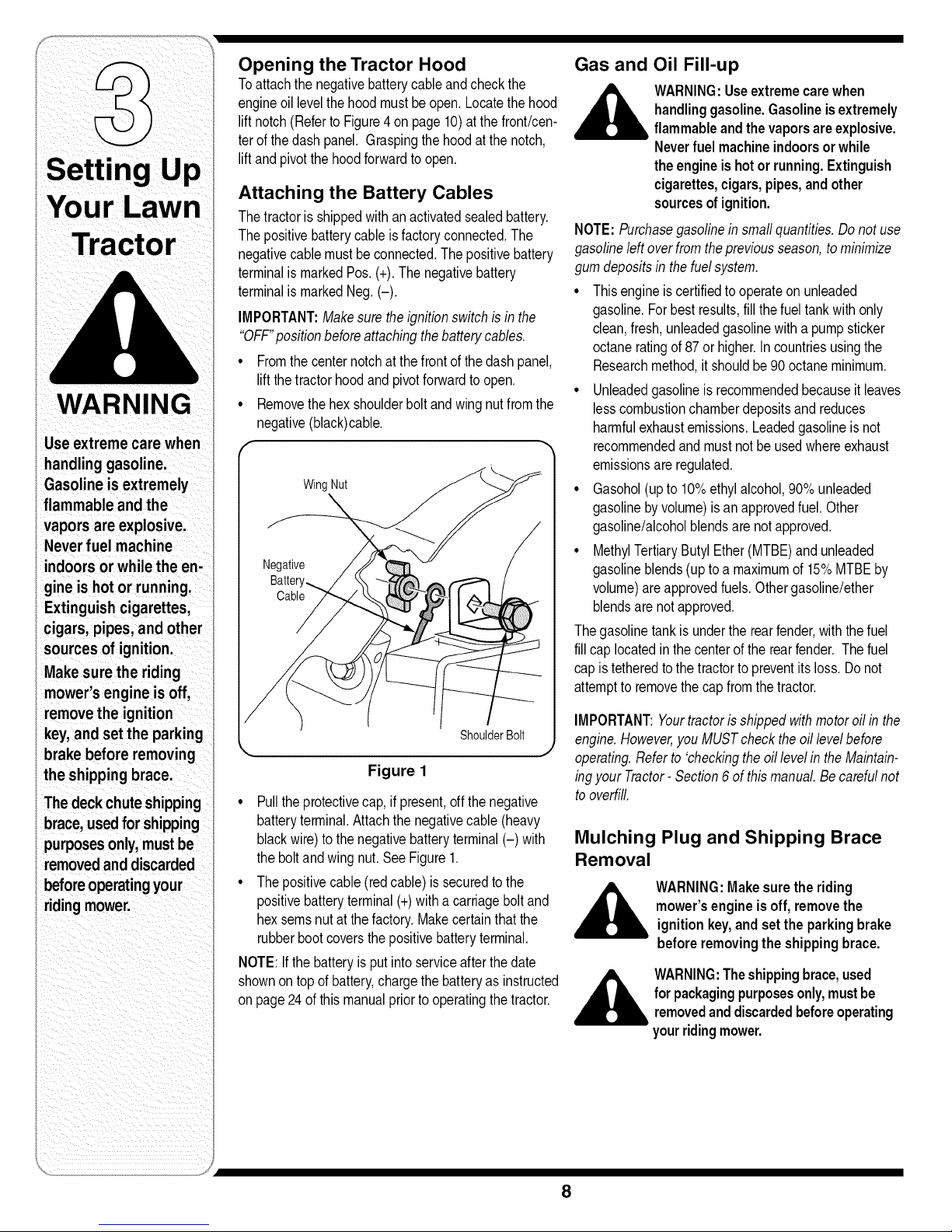
• Removethehexshoulderboltand wingnutfromthe
negative(black)cable,
WingNut
Figure 1
• Pulltheprotectivecap,if present,offthe negative
batteryterminal,Attachthenegativecable(heavy
blackwire)to thenegativebatteryterminal(-) with
theboltandwingnut,SeeFigure1,
• Thepositivecable(redcable)issecuredtothe
positivebatteryterminal(+)withacarriageboltand
hexseresnut atthe factory,Makecertainthatthe
rubberbootcoversthepositivebatteryterminal,
NOTE:Ifthe batteryis putintoserviceafterthedate
shownontopof battery,chargethebatteryas instructed
onpage24ofthis manualpriortooperatingthe tractor.
Gas and Oil Fill-up
4_ WARNING:Useextremecarewhen
NOTE:Purchasegasolineinsmallquantities.Donotuse
gasolineleftoverfromthepreviousseason,tominimize
gumdepositsin thefuelsystem.
• Thisengineiscertifiedto operateonunleaded
gasoline.Forbestresults,fill thefuel tankwithonly
clean,fresh,unleadedgasolinewitha pumpsticker
octaneratingof 87or higher.Incountriesusingthe
Researchmethod,it shouldbe90 octaneminimum.
• Unleadedgasolineisrecommendedbecauseit leaves
lesscombustionchamberdepositsand reduces
harmfulexhaustemissions.Leadedgasolineisnot
recommendedandmust notbeusedwhereexhaust
emissionsareregulated.
• Gasohol(upto 10%ethylalcohol,90%unleaded
gasolinebyvolume)isanapprovedfuel.Other
gasoline/alcoholblendsarenotapproved.
• MethylTertiaryButylEther(MTBE)andunleaded
gasolineblends(uptoa maximumof 15%MTBEby
volume)areapprovedfuels.Othergasoline/ether
blendsarenotapproved.
Thegasolinetankisunderthe rearfender,withthefuel
fillcap locatedinthecenterofthe rearfender. Thefuel
capis tetheredto thetractortopreventitsloss.Donot
attempttoremovethecapfromthetractor.
IMPORTANT:Yourtractorisshippedwithmotoroil in the
engine.However,youMUSTcheckthe oillevelbefore
operating.Referto 'checkingtheoillevelinthe Maintain-
ingyour Tractor-Section6 ofthismanual.Becarefulnot
tooverfill.
handlinggasoline.Gasolineis extremely
flammableandthevaporsareexplosive.
Neverfuel machineindoorsor while
theengineishotor running.Extinguish
cigarettes,cigars,pipes,andother
sourcesofignition.
Mulching Plug and Shipping Brace
Removal
WARNING:Makesurethe riding
mower'sengineis off,removethe
ignitionkey,andset theparkingbrake
beforeremovingthe shippingbrace.
,__ WARNING:Theshippingbrace,used
forpackagingpurposesonly,mustbe
removedanddiscardedbeforeoperating
yourridingmower.
8
Page 9
A
WARNING:Themowingdeckiscapable
ofthrowingobjects.Neveroperatethe
mowerdeckwithoutthechutedeflector
initsdownposition,evenwiththe
mulchingpluginstalled.Failuretodoso
couldresultinseriouspersonalinjury
and/orpropertydamage.
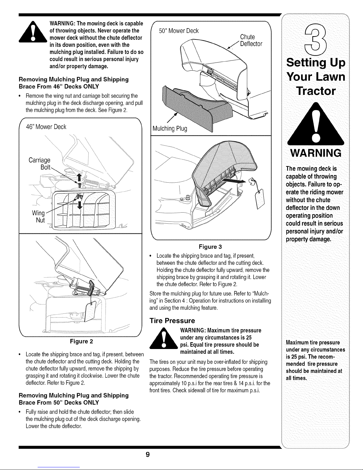
50"MowerDeck
Chute
Deflector
Removing Mulching Plug and Shipping
Brace From 46" Decks ONLY
• Removethe wingnut andcarriageboltsecuringthe
mulchingpluginthedeckdischargeopening,and pull
themulchingplugfromthe deck,See Figure2,
ff46"Mower Deck
Carriage
Wing
Nut
VlulchingPlug
\ /
Figure 3
• Locatetheshippingbraceandtag,if present,
betweenthe chutedeflectorandthecuttingdeck.
Holdingthechutedeflectorfullyupward,removethe
shippingbracebygraspingitand rotatingit.Lower
thechutedeflector.Referto Figure2.
Storethe mulchingplugfor futureuse.Referto"Mulch-
ing"inSection4 :Operationforinstructionson installing
andusingthe mulchingfeature.
rLawn
WARNING
The mowing deck is
capable of throwing
objects. Failure to op-
erate the riding mower
without the chute
deflector in the down
operating position
could result in serious
personal injury and/or
property damage.
Figure 2
Locatethe shippingbraceandtag, ifpresent,between
thechutedeflectorandthecuttingdeck,Holdingthe
chutedeflectorfullyupward,removetheshippingby
graspingit androtatingitclockwise,Lowerthechute
deflector,RefertoFigure2,
Removing Mulching Plug and Shipping
Brace From 50" Decks ONLY
• Fullyraiseandholdthechutedeflector;thenslide
themulchingplugout ofthe deckdischargeopening,
Lowerthechutedeflector,
Tire Pressure
A ARNING:Maximumtirepressure
Thetireson yourunitmaybeover-inflatedforshipping
purposes,Reducethetire pressurebeforeoperating
thetractor.Recommendedoperatingtire pressureis
approximately10p,s,iforthe reartires& 14p,s,i,forthe
fronttires,Checksidewallof tireformaximump,s,i,
underanycircumstancesis 25
psi.Equaltirepressureshouldbe
maintainedat alltimes.
9
Maximumtire pressure
underanycircumstances
is25 psi.Therecom-
mendedtire pressure
shouldbemaintainedat
all times.
Page 10
NOTE:
Any referenceinthis
manualto the RGHT
or LEFTside ofthe
tractor isobservedfrom
operator'sposition.
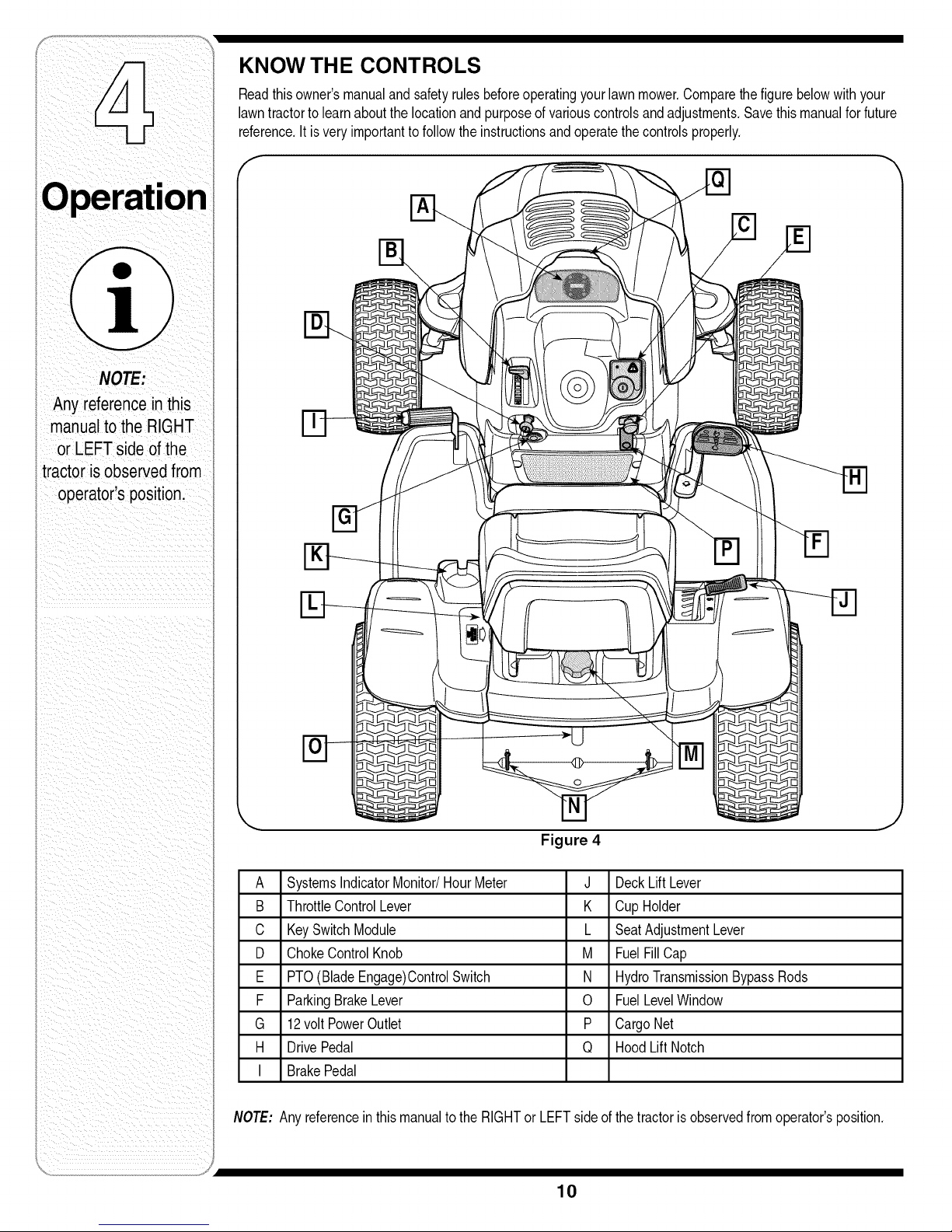
KNOW THE CONTROLS
Readthisowner'smanualandsafetyrulesbeforeoperatingyourlawnmower,Comparethe figurebelowwithyour
lawntractortolearnaboutthelocationand purposeof variouscontrolsandadjustments,Savethismanualforfuture
reference.It isveryimportanttofollowtheinstructionsandoperatethecontrolsproperly.
A SystemsIndicatorMonitor/HourMeter J DeckLiftLever
B ThrottleControlLever K CupHolder
C KeySwitchModule L SeatAdjustmentLever
D ChokeControlKnob M FuelFillCap
E PTO(BladeEngage)ControlSwitch N HydroTransmissionBypassRods
F ParkingBrakeLever 0 FuelLevelWindow
G 12volt PowerOutlet P CargoNet
H DrivePedal Q HoodLiftNotch
I BrakePedal
NOTE:Any referenceinthis manualtothe RIGHTor LEFTsideofthetractoris observedfromoperator'sposition,
Figure 4
10
Page 11

Throttle Control Lever
Thethrottlecontrollevercontrols
thespeedofthe engine,When
set ina givenposition,thethrottle
willmaintaina uniformengine
speed,
IMPORTANT:Whenoperating
thetractorwiththecuttingdeck
engaged,throttlecontrollever
mustalwaysbein theFAST
(rabbit)position.
Choke Control
Thechokecontrolknob islocated
on thelowerleft sideof thedash
panelandisactivatedbypulling
outward,Activatingthechokecontrolclosesthechoke
plateon the carburetorandaidsin startingtheengine,
Fast
Position
Slow
Position
Brake Pedal
Thebrakepedalis locatedatthe frontoftheright running
boardandisusedforquickstops,or settingtheparking
brake,Thispedalmustbe FULLYdepressedto activate
thesafetyinterlockswitchwhenstartingthetractor.
Parking Brake Lever
NOTE:Theparkingbrakemustbe setiftheoperator
leavestheseatwiththe enginerunning;otherwisethe
enginewillautomaticallyshutoff, h._,._
• Tosettheparkingbrake,fullydepress
thebrakepedaland pushthe bottom
of parkingbrakeleverinward, Seethe
imageto therightforparkingbrake
identification,Holdtheleverin while
removingyour footfromthebrake
pedal,Bothparkingbrakeleverand
brakepedalwill staydepressed,
• Toreleasetheparkingbrake,depress
thebrakepedalslightly,The parkingbrakeleverwill
thenreturnto itsoriginalposition,
IMPORTANT:Alwayssettheparkingbrakewhenleaving
thetractorunattended.
Drive Pedal
Thedrivepedalislocatedonthe rightsideofthetractor,
alongtherunningboard,Depresstheupperportionof
thedrive pedalforwardtocausethetractortotravel
forward,Depressthe lowerportionofthe drive 41.
pedalwiththeballof yourrightfoot(NOTyour
heel)tocausethe tractortotravelin reverse,
Groundspeedis alsocontrolledwiththe drive
pedal,Thefurtherforwardor rearwardthatthe
pedalispivoted,thefasterthetractorwilltravel.
Thetractorwill slowandthe pedalwill return
to itsoriginalpositionwhenthepedalisnot
depressed,
PTO (Blade Engage)
Control Switch
Toengagethe electricPTOand
providepowertothe cuttingdeck,
pulloutwardonthePTOcontrol
switchknob.Pushthe switchknob
inwardtodisengagethePTOand
stopthecuttingdeck.
NOTE: ThePTOControlSwitch
mustbe inthedisengaged(OFF)
positionwhenstartingtheengine,
F PTO
! t
o I
OFF ONj
Key Switch Module
Thekeyswitchmoduleis
usedto startandstopthe
engine,Itis alsousedto
activatethe REVERSE
CAUTIONMODE.Insert
keyintothe keyswitch
moduleand
tothe STARTposition,
Releasethe keyinto
theNORMALMOWING
positiononceenginehas
started.
Tostopthe engine,turntheignitionkeycounterclockwise
tothe STOPposition.
__b ARNING:Neverleave a running
IMPORTANT:Priortooperatingthetractor,referto both
SafetyInterlockSwitcheson page13andStartingThe
Engineonpage14ofthismanualfordetailedinstructions
regardingthe IgnitionSwitchModuleandoperatingthe
tractorin REVERSECAUTIONMODE.
__lb ARNING:Nevermovethekey into
disengagePTO,moveshiftleverinto
neutralposition,setparkingbrake,
stopengineand removekeyto prevent
machineunattended.Always
unintendedstarting.
theStart position whilethe engineis
running.Doingsomaycausedamageto
yourengine'sstarter.
CHILDREN AROUND
©
12V Power Outlet
The12Vpoweroutletislocatedbelowthechokecontrol
ontheleft sideofthedashpanel.It is usedfor the
convenienceof pluggingin accessoriesthatrequirea
powersourcewitha maximumloadof5 arnpsat 12volts,
running machine
unattended.Always
parkingbrake,stop
engine andremove
]
MPORTANT
When operatingthe
tractorwiththe cuttingdeck
engaged,throttlecontrol
lever mustalwaysbein the
FAST (rabbit)position.
Alwayssetthe parking
brake whenleavingthe
tractor unattended.
Priortooperatingthe
tractor, refertoboth Safety
InterlockSwitcheson page
13 andStartingTheEngine
on page14ofthismanual
fordetailedinstructions
g theKeySwitch
odu!eandoperating
the tractor in REVERSE
CAUTIONMODE.
11
Page 12
intotheStart position
i maycausedamage to
i your engine's starter.
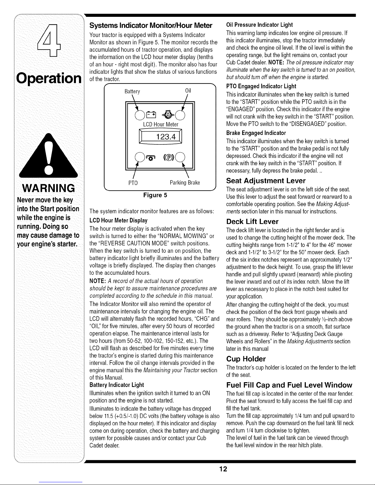
Systems Indicator Monitor/Hour Meter
Yourtractoris equippedwith a SystemsIndicator
Monitoras shownin Figure5. The monitorrecordsthe
accumulatedhoursof tractoroperation,anddisplays
theinformationon the LCDhourmeterdisplay(tenths
of an hour- right most digit). Themonitoralsohasfour
indicatorlightsthat showthe statusofvariousfunctions
ofthe tractor.
Battery Oil
LCDHourMeter
123.4-
/
PTO ParkingBrake
Figure 5
Thesystem indicatormonitor featuresareas follows:
LCDHourMeterDisplay
Thehour meterdisplayis activatedwhen the key
switch isturnedto eitherthe "NORMALMOWING"or
the"REVERSECAUTIONMODE"switchpositions.
Whenthe keyswitch isturned to an on position, the
batteryindicator light briefly illuminatesand the battery
voltage isbriefly displayed.Thedisplay thenchanges
to the accumulatedhours.
NOTE:A recordof theactual hours of operation
shouldbe kept toassuremaintenanceproceduresare
completedaccordingto theschedulein this manual.
TheIndicatorMonitorwill alsoremindtheoperatorof
maintenanceintervalsforchangingtheengineoil. The
LCDwillalternatelyflashthe recordedhours,"CHG"and
"OIL"forfive minutes,afterevery50hoursof recorded
operationelapse.The maintenanceintervallasts for
two hours(from50-52, 100-102,150-152,etc.).The
LCDwillflashas describedforfiveminuteseverytime
thetractor'sengineisstarted duringthis maintenance
interval.Followthe oil changeintervalsprovidedinthe
enginemanualthisthe Maintainingyour Tractorsection
ofthis Manual.
Battery Indicator Light
Illuminateswhentheignitionswitchit turnedtoan ON
positionandtheengineis notstarted.
Illuminatesto indicatethebatteryvoltagehasdropped
below11.5(+0.5/-1.0)DCvolts(the batteryvoltageis also
displayedonthe hourmeter).Ifthisindicatoranddisplay
comeon duringoperation,checkthebatteryandcharging
systemforpossiblecausesand/orcontactyourCub
Cadetdealer.
(®)
Oil PressureIndicatorLight
Thiswarninglampindicateslowengineoil pressure.If
thisindicatorilluminates,stopthe tractorimmediately
andcheckthe engineoil level.Iftheoil levelis withinthe
operatingrange,butthe lightremainson,contactyour
CubCadetdealer.NOTE:Theoilpressureindicatormay
illuminatewhenthe keyswitchis turnedtoanonposition,
butshouldtumoff whentheengineisstarted.
PTOEngagedIndicator Light
Thisindicatorilluminateswhenthe keyswitchisturned
tothe "START"positionwhilethePTOswitchis inthe
"ENGAGED"position.Checkthisindicatorifthe engine
willnotcrankwiththekeyswitchinthe"START"position.
MovethePTOswitchtothe "DISENGAGED"position.
Brake EngagedIndicator
Thisindicatorilluminateswhenthe keyswitchisturned
tothe "START"positionandthebrakepedalis notfully
depressed.Checkthisindicatorif theenginewill not
crankwiththekeyswitchin the"START"position.If
necessary,fullydepressthebrakepedal...
Seat Adjustment Lever
Theseatadjustmentleverisonthe left sideoftheseat.
Usethisleverto adjusttheseatforwardorrearwardtoa
comfortableoperatingposition.SeetheMakingAdjust-
mentssectionlaterinthis manualfor instructions.
Deck Lift Lever
Thedecklift leverislocatedintherightfenderandis
usedto changethecuttingheightofthe mowerdeck.The
cuttingheightsrangefrom 1-1/2"to4"forthe46" mower
deckand1-1/2"to3-1/2"forthe50" mowerdeck.Each
ofthe sixindexnotchesrepresentan approximately1/2"
adjustmenttothedeck height.Touse,graspthe lift lever
handleandpullslightlyupward(rearward)whilepivoting
theleverinwardandout ofitsindexnotch.Movethe lift
leveras necessaryto placeinthenotchbestsuitedfor
yourapplication.
Afterchangingthecuttingheightofthe deck,you must
checkthe positionofthe deckfrontgaugewheelsand
rearrollers.Theyshouldbeapproximately1/2-inchabove
thegroundwhenthetractorison asmooth,flat surface
suchasadriveway.Referto"AdjustingDeckGauge
WheelsandRollers"intheMakingAdjustmentssection
laterin thismanual
Cup Holder
Thetractor'scupholderislocatedonthefendertothe left
ofthe seat.
Fuel Fill Cap and Fuel Level Window
Thefuel fillcapislocatedin thecenterof therearfender.
Pivottheseatforwardto fullyaccessthefuelfillcapand
fillthe fueltank.
Turnthefillcap approximately1/4turnandpullupwardto
remove.Pushthe capdownwardonthe fueltankfill neck
andturn1/4turnclockwisetotighten.
Thelevelof fuelin thefueltankcanbeviewedthrough
thefuellevelwindowin therearhitchplate.
12
Page 13
Cargo Net
Convenientlylocatedon thetractor'sdashpanel,the
cargonet canbeusedto storepersonalitemswhile
operatingthelawntractor.
Hydro Transmission Bypass Rods
Thehydrotransmissionbypassrodsarelocatedatthe
backofthe tractorabovetherearhitchplate,When
engaged,theseleversopena hydropumpbypass
valveineachtransmissionwhichallowsthe tractorto
be pushedshortdistancesmanually,See "Movingthe
TractorManually"laterinthis section,
Headlights
Thetractorheadlightsareturnedon whenevertheignition
switchisturnedto eitheroftherunpositions,
Safety Interlock System
Thesafetyinterlocksystemis designedforsafeoperation
ofthe tractor.If thissystemshouldevermalfunction,do
notoperatethetractor,immediatelycontactyourCub
Cadetdealer.
° Thesafetyinterlocksystempreventstheenginefrom
startingunlessthe parkingbrakeis engagedandthe
PTOswitchis inthedisengaged(OFF)position,
• Thesafetyinterlocksystemwill automaticallyshut
off theengineif theoperatorleavestheseatbefore
engagingtheparkingbrake,
• Thesafetyinterlocksystemwill automaticallyshutoff
theengineif theoperatorleavesthe tractor'sseatwith
the PTO(BladeEngage)switchengaged,regardless
ofwhetherthe parkingbrakeisengaged,
• Withtheignitionkeyinthe NORMALMOWING
position,theelectricPTOclutchwill automaticallyshut
off ifthe PTOswitchisinthe engaged(ON)position
andthedrivepedalisdepressedforReversetravel,
tobypasstheSafetyInterlockSwitchesin
__b ARNING:Tamperingwithorattempting
anywaywillvoidyourtractor'swarranty.
Donotoperatethetractorif theinterlock
systemismalfunctioning.
Reverse Caution Mode
operatingthetractorinthe REVERSE
__b ARNING:Useextremecautionwhile
CAUTIONMODE.Alwayslookdownand
behindbeforeandwhilebacking.Do
notoperatethetractorwhenchildren
orothersarearound.Stopthetractor
immediatelyifsomeoneentersthearea.
TheREVERSECAUTIONMODE
positionofthe keyswitchmoduleallowsthetractorto be
operatedinreversewiththe blades(PTO)engaged,
IMPORTANT:Mowingin reverseis notrecommended,
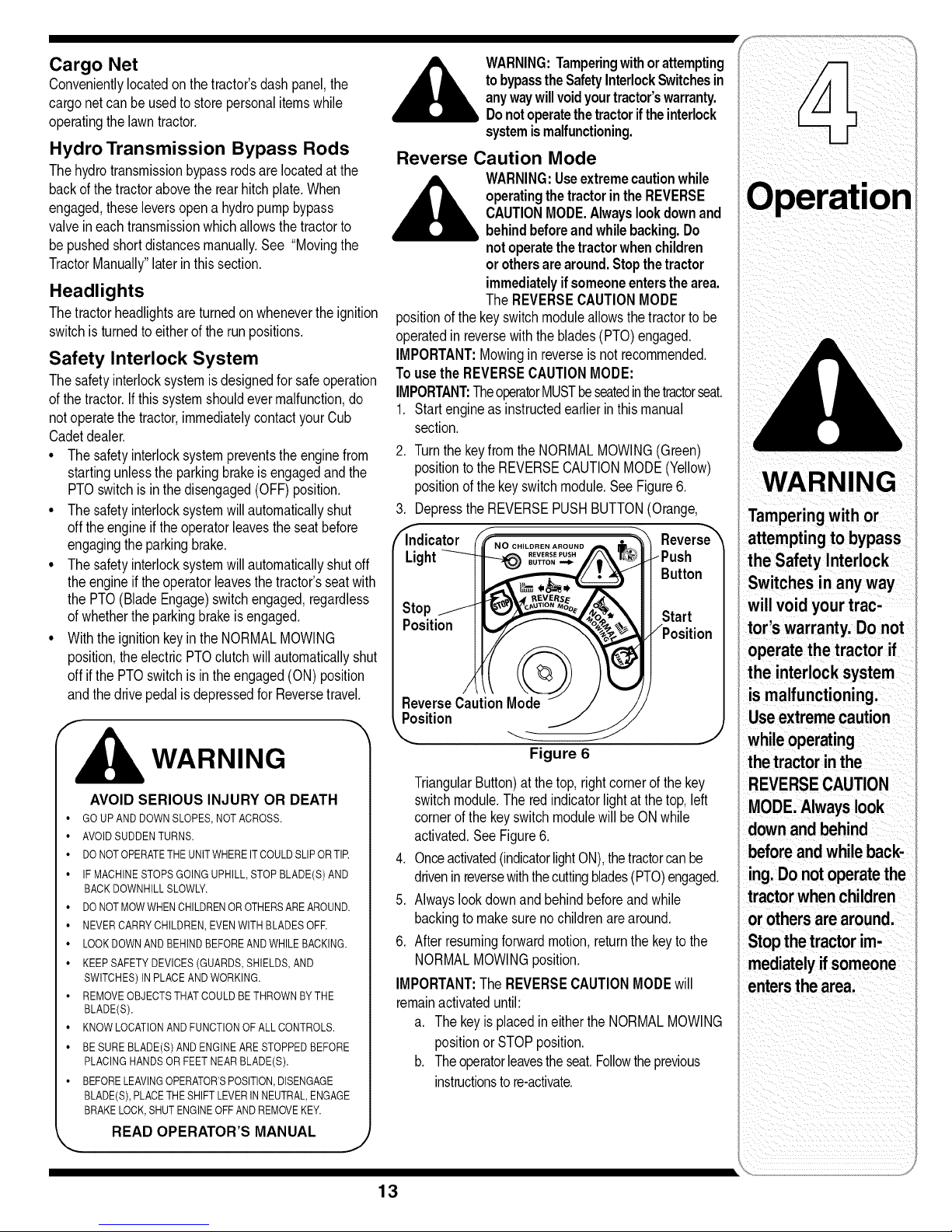
Tousethe REVERSECAUTIONMODE:
IMPORTANT:TheoperatorMUSTbeseatedinthetractorseat.
1. Startengineas instructedearlierinthis manual
section,
2. TurnthekeyfromtheNORMALMOWING(Green)
positiontothe REVERSECAUTIONMODE(Yellow)
positionofthe keyswitchmodule.SeeFigure6.
3. Depressthe REVERSEPUSHBUTTON(Orange,
WARNING
Tamperingwith or
('_ndicator (FfNo ........ • _'_ Reverse_ attempting to bypass
Light___Push - I
_1 Butt°n/ theSafetylnterlock
Switches inanyway
st°p.../II _'__,,\ IllStart | will void your trac-
operate the tractor if
vos,uon /_(// -__ Position I t°r's warranty.Do not
ReverseCautionMode / / // | is malfunctioning.
the interlocksystem
F
WARNING
AVOID SERIOUS INJURY OR DEATH
• GO UP AND DOWN SLOPES, NOT ACROSS.
• AVOID SUDDEN TURNS.
• DO NOTOPERATETHE UNIT WHERE IT COULDSLIP ORTIE
• IF MACHINE STOPS GOING UPHILL, STOP BLADE(S) AND
BACK DOWNHILL SLOWLY.
• DO NOT MOWWHEN CHILDREN OR OTHERSARE AROUND.
• NEVER CARRY CHILDREN, EVEN WITH BLADES OFF.
• LOOK DOWNAND BEHIND BEFOREAND WHILE BACKING.
• KEEP SAFETY DEVICES (GUARDS, SHIELDS, AND
SWITCHES) IN PLACE AND WORKING.
• REMOVE OBJECTS THAT COULD BE THROWN BY THE
BLADE(S).
• KNOW LOCATION AND FUNCTION OF ALL CONTROLS.
• BE SURE BLADE(S) AND ENGINE ARE STOPPED BEFORE
PLACING HANDS OR FEET NEAR BLADE(S).
• BEFORE LEAVINGOPERATOR'SPOSITION, DISENGAGE
BLADE(S), PLACETHE SHIFT LEVER IN NEUTRAL, ENGAGE
BRAKE LOCK,SHUT ENGINE OFFAND REMOVE KEY.
READ OPERATOR'S MANUAL
Useextremecaution
Figure 6
TriangularButton)atthe top,rightcornerofthekey
switchmodule.The redindicatorlightat thetop,left
cornerof thekeyswitchmodulewillbe ONwhile
activated,SeeFigure6.
4. Onceactivated(indicatorlightON),thetractorcanbe
driveninreversewiththecuttingblades(PTO)engaged,
5. Alwayslookdownandbehindbeforeandwhile
backingtomakesurenochildrenarearound,
6. Afterresumingforwardmotion,returnthekeytothe
NORMALMOWINGposition,
IMPORTANT:TheREVERSECAUTIONMODEwill
whileoperating
the tractorin the
REVERSECAUTION
MODE.Alwayslook
downandbehind
beforeandwhileback-
ing.Donotoperatethe
tractorwhenchildren
or othersarearound.
Stopthetractorim-
mediatelyifsomeone
entersthe area.
remainactivateduntil:
a. The keyisplacedineithertheNORMALMOWING
positionor STOPposition,
b. Theoperatorleavestheseat,Followtheprevious
instructionsto re-activate.
J
13
Page 14
WARNING
Ifyou strikea foreign
object, stopthe
engine, disconnect
the spark plug
wire(s) anti ground
against the engine.
Thoroughly inspect
the machinefoi any
damage. Repair dam-
age before restarting.
Donotleavethe seat
ofthetractorwithout
first placingthe PTO
leverinthedisen-
gaged(Blade Stop)
position,depressing
the brakepedaland
engagingtheparking
brake.If leavingthe
tractorunattended,
alsoturnthe ignition
keyoffand remove
the key.
Starting the Engine
NOTE: Referto theTRACTORSET-UPonpage7 of this
manualforgasolineandoil fill-upinstructions,
1, Insertthetractorkeyintothekeyswitchmodule.
2, DisengagethePTO(BladeEngage)lever/knob,
3, Engagethetractor'sparkingbrake,
4, Pullthechokecontrolknoboutwardintothefullchoke
position(awarmenginemaynotrequirechoking),
5, Movethe throttlecontrollevertomidwaybetweenthe
SLOWandFASTpositions,
5, TurntheignitionkeyclockwisetotheSTARTposition,
Aftertheenginestarts,releasethekey,Itwill returnto
theNORMALMOWINGposition.
IMPORTANT:Do notholdthe keyin the STARTposition
forlongerthantensecondsata time,Doingsomaycause
damagetoyourengine'selectricstarter.
6, Aftertheenginestarts,graduallypushthechokeknob
fullyinwardastheenginewarmsup,
NOTE: Do notusethe chokecontroltoenrichthefuel
mixture,exceptasnecessarytostartandwarmupthe
engine,
If leavingthetractorunattended,alsoturnthe
ignitionkeyoff and removethe key,
Donot mowon slopeinexcessof 15degrees(a rise
ofapproximately2-1/2feetevery10feet),
Planyourmowingpatternto avoiddischargeof
materialstowardroads,sidewalks,bystandersand
thelike,Also,avoiddischargingmaterialagainst
a wallor obstructionwhichmaycausedischarged
materialtoricochetbacktowardtheoperator.
Stopping the Engine
ject, stoptheengineanddisconnect
___# ARNING: Ifyoustrikea foreignob-
1, If thebladesareengaged,disengagethePTO,
2, Movethe throttlecontrollevertomidwaybetweenthe
halfand fullthrottle.Thenturntheignitionkeycounter-
clockwisetotheOFFposition.
3, Removethekeyfromtheignitionswitchto prevent
unintendedstarting.
thesparkplugwire(s). Thoroughly
inspectthe machinefor anydamage.
Repairdamagebeforerestarting.
Driving The Tractor
IMPORTANT:Avoidsuddenstarts,excessivespeedand
suddenstops.
° Brieflydepressthebrakepedalto releasethe
parkingbrake.Movethethrottleleverintothe
FAST(rabbit)position,
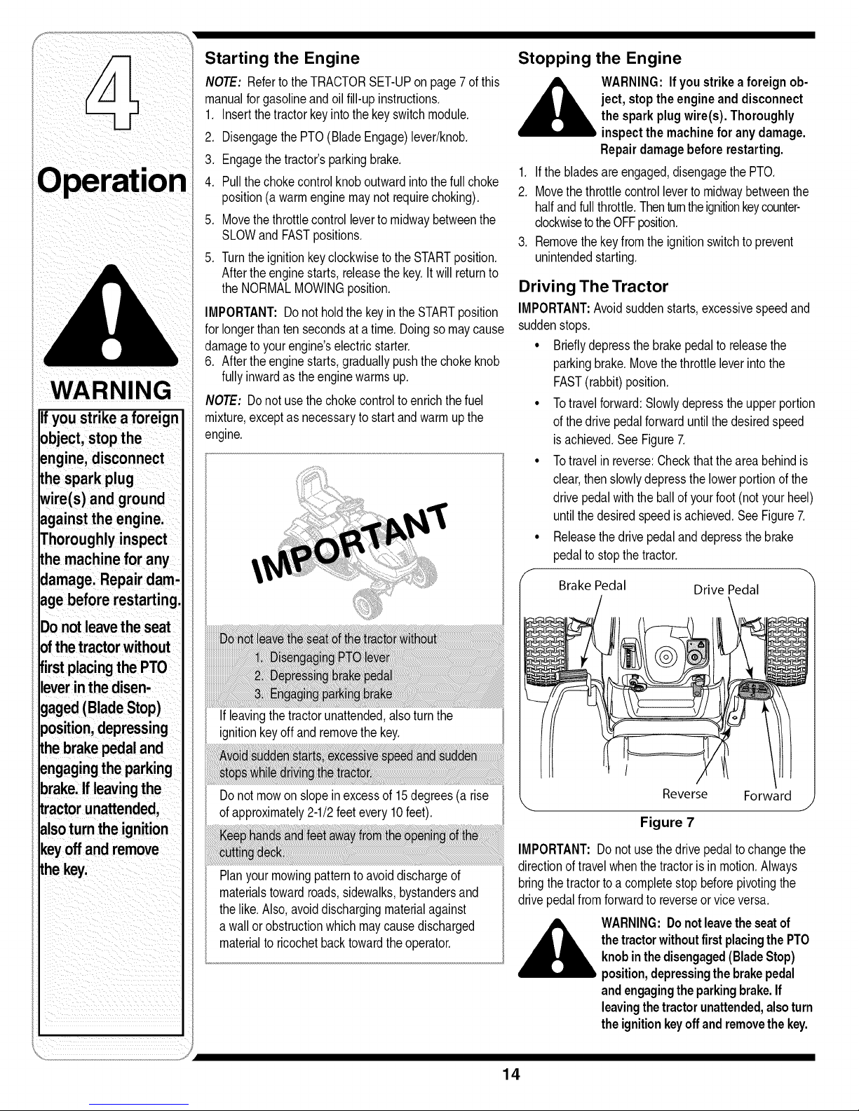
• Totravelforward:Slowlydepresstheupperportion
ofthe drivepedalforwarduntilthedesiredspeed
isachieved,SeeFigure7,
• Totravelin reverse:Checkthattheareabehindis
clear,thenslowlydepressthelowerportionof the
drivepedalwiththe ballof yourfoot(notyourheel)
untilthe desiredspeedisachieved,SeeFigure7,
° Releasethe drivepedalanddepressthebrake
pedalto stopthe tractor.
Brake Pedal Drive Pedal
k. Reverse Forward j
Figure 7
IMPORTANT:Do notusethedrivepedalto changethe
directionof travelwhenthe tractorisin motion.Always
bringthetractortoa completestopbeforepivotingthe
drivepedalfromforwardto reverseorviceversa,
thetractor withoutfirst placing thePTO
__lb ARNING:Donot leavethe seatof
knob inthe disengaged(BladeStop)
position,depressingthe brakepedal
andengagingtheparking brake.If
leavingthe tractor unattended,alsoturn
the ignition keyoff andremovethe key.
14
Page 15
Steering the Tractor
Youri1000seriestractoris equippedwith aninnovative
steeringdesignwhichis somewhatdifferentfromthatof
thetraditionalsteeringwheeltypelawntractor.Turning
thesteeringwheelnotonly turnsthefrontwheels,but
alsocontrolsthedrivelinkageofthetwo hydrotransmis-
sionsthatdrivethe tractor.Thisfeatureallowsyouto
varythe radiusof turnsfroma normalwideturn downto
a zeroturn.Somepracticemayberequiredtobecome
accustomedtothe steeringofyourtractor.Thesteering
worksas follows:
° Thesteeringwheelturnsapproximatelytwo turnsstop
to stop.Withthecenterpositionbeingthestraight
aheadposition.
° Minorturnsof thesteeringwheelfromthecenter
position(up toapprox.100) willturnonlythefront
axlesand resultinwiderturns.
° Increasingtheturn ofthesteeringwheel(beyond10°)
resultsinincreasinglytighterturns.Asthe steering
mechanismturnsthe frontwheels,it alsochanges
thepositionof thetransmissiondrivelinkageto slow
downthe innerrearwheelintheturnandadjustthe
speedof theouterwheelas necessarytocomplete
thedesiredturn.Turnthe steeringwheelbacktothe
centerpositionas theturn iscompleted.
NOTE:It isnotnecessarytoreleasethedrivepedal
whenmakinga turn.Thechangetothetransmission
linkageoccursregardlessof howfar thedrivepedalis
depressed.Whenthesteeringwheelis straightened,the
tractorwillreturnto thespeedset bythedrivepedal.
° Turningthesteeringwheelfullytoits stopineither
directionwillfullyturnthefrontwheels,reversethe
directionofthe innerwheelandadjusttheouterwheel
speedto executeazeroturninthechosendirection.
Turnthe steeringwheelbacktothecenterpositionas
theturn iscompleted.
NOTE:Asthe steeringwheelis turnedfurthertoward
itsstop,theeffortneededto tumthesteeringwheel
increases.
IMPORTANT:Makingtightor zeroturnson grasswill
greatlyincreasethe potentialfor defacementof theturf.
Driving On Slopes
IMPORTANT:RefertotheSLOPEGAUGEonpage3tohelp
determineslopeswhereyoumayoperatethetractorsafely.
• Mowupanddown slopes,neveracross.
• Watchforholes,ruts,bumps,rocks,orotherhidden
objects.Uneventerraincouldoverturnthe machine.
Tallgrasscan hideobstacles.
• Avoidturnswhendrivingona slope.If a turnmust
be made,turndownhillon theslope.Turninguphill
increasesthepossibilityof a tractorrollover.
• Avoidstoppingwhendrivingupaslope.If itis neces-
saryto stopwhiledrivingupaslope,startupsmoothly
andcarefullyto reducethepossibilityof flippingthe
tractoroverbackward.
Moving the Tractor Manually
Ifforanyreasonthetractorwillnotdriveoryouwishto
movethe tractor,engagethetwohydrotransmission
bypassrodsto manuallymovethetractorshortdistances.
IMPORTANT:Nevertowordragthetractorwiththerear
wheelsonthe ground.Evenwiththe bypassrodsengaged.
Doingsowilldamagethe transmissions.
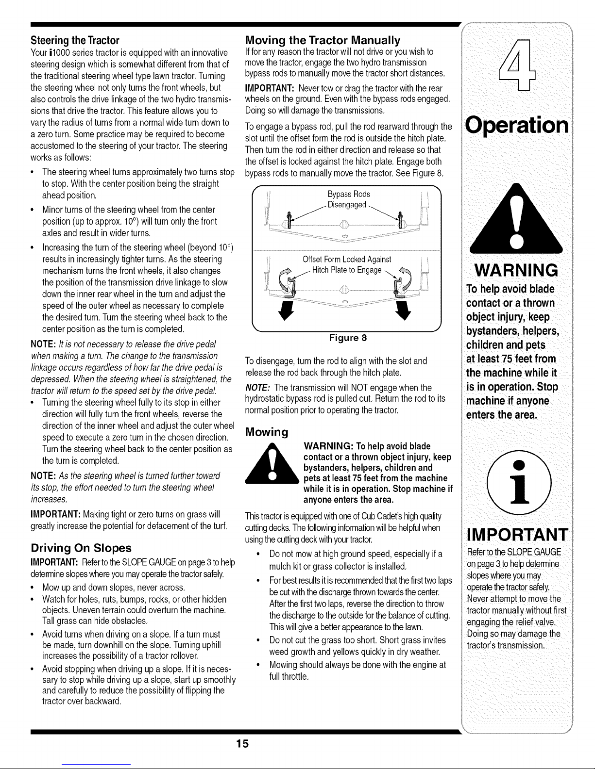
Toengagea bypassrod,pullthe rodrearwardthroughthe
slotuntilthe offsetformtherodisoutsidethehitchplate.
Thenturnthe rodineitherdirectionandreleasesothat
theoffsetis lockedagainstthehitchplate.Engageboth
bypassrodstomanuallymovethetractor.SeeFigure8.
BypassRods _
/ Disengaged
i. 4' /
OffsetFormLockedAgainst
J
Figure 8
Todisengage,turntherodto alignwiththeslotand
releasetherodbackthroughthehitchplate.
NOTE: Thetransmissionwill NOTengagewhenthe
hydrostaticbypassrodis pulledout. Returntherodto its
normalpositionpriortooperatingthetractor.
Mowing
WARNING: Tohelpavoidblade
contactora thrownobjectinjury,keep
bystanders,helpers,childrenand
petsat least75 feet from the machine
whileit isinoperation.Stopmachineif
anyoneentersthearea.
Thistractorisequippedwithoneof CubCadet'shighquality
cuttingdecks.Thefollowinginformationwillbehelpfulwhen
usingthecuttingdeckwithyourtractor.
• Do notmowathighgroundspeed,especiallyifa
mulchkit orgrasscollectorisinstalled.
• Forbestresultsitisrecommendedthatthefirsttwolaps
becutwiththedischargethrowntowardsthecenter.
Afterthefirsttwolaps,reversethedirectionto throw
thedischargeto theoutsideforthebalanceofcutting.
Thiswillgivea betterappearancetothelawn.
• Do notcutthegrasstooshort.Shortgrassinvites
weedgrowthandyellowsquicklyin dryweather.
• Mowingshouldalwaysbedonewiththe engineat
fullthrottle.
WAR NING
To helpavoid blade
contact or athrown
bystanders,helpers,
children and pets
at least 75 feet from
the machine while it
IMPORTANT
RefertotheSLOPEGAUGE
onpage3tohelpdete_ine
slopeswhereyoumay
operatethetractorsafelyl
Never attempttomovethe
tractor manuallywithoutfirst
engagingthe reliefvalve.
Doing so rnaydamagethe
tractor,stransmission.
i_ :_ /i _i iiiiiiiii_: I
\i_,:...........................................j
15
Page 16
WARNING
The mowing deck is
capable of throwing
objects. Never operate
the mower deck with-
out the chute deflector
in the down position
Failureto do so could
result in serious
personal injury and/or
property damage.
* Underheavierconditionsit maybenecessarytogo
backoverthecutareaa secondtimetogetacleancut.
. Donotattemptto mowheavybrushandweeds
andextremelytall grass.Yourtractorisdesignedto
mowlawns,notclearbrush.
. Keepthebladessharpand replacethebladeswhen
worn.Referto CuttingBladesonpage25of this
manualforproperbladesharpeninginstructions.
IMPORTANT:Whenstoppingthetractorforanyreason
whileona grasssurface,always
* Placethe shiftleverin neutral,
. Engagetheparkingbrake,
. Shutengineoff andremovethe key.
Doingso willminimizethepossibilityofhavingyourlawn
"browned"byhot exhaustfromyourtractor'srunning
engine.
Mulching
Thei1000seriestractordecksareequippedwitha
mulchingkit. Themulchkitwhichincorporatesspecial
blades,alreadyon yourtractor,ina processofrecirculating
grassclippingsrepeatedlybeneaththe cuttingdeck.The
ultra-fineclippingsarethenforcedbackintothelawnwhere
theyactasa naturalfertilizer.
Observethefollowingpointsfor bestresultswhenmulching:
. Neverattempttomulchifthelawnis damp.Wetgrass
tendsto stickto the undersideofthecuttingdeck
preventingpropermulchingoftheclippings.
. Donotattempttomulchmorethan 1/3the totalheight
ofthe grassor approximately1-1/2inches.Doingso
willcausethe clippingsto clumpup beneaththedeck
andnotbemulchedeffectively.
. Maintaina slowgroundspeedto allowthegrass
clippingsmoretimetoeffectivelybe mulched.
. AlwayspositionthrottlecontrolleverintheFAST(rabbit)
positionandallowittoremaintherewhilemowing.Failing
tokeeptheengineatfullthrottleplacesstrainonthe
tractor'sengineanddoesnotallowthebladestoproperly
mulchgrass.
NOTE: It isnotnecessaryto removethe chutedeflector
tooperatethemowerwiththe mulchpluginstalled.
• Themulchpluginstalledat thefactorywasremoved
earlierinthe"SettingupyourLawnTractor"section.To
reinstallthemulchingplug,proceedasfollows:
Installing Mulching Plug on 46" Decks ONLY
• Raiseandholdthechutedeflectorinupposition.
° Locatethe1/4inchholeinthetopofthemulchingplug.
Withtheholefacingupwardinsertthemulchingplugfully
intothedischargeopeningofthedeck.
° Alignthemulchingplugholewiththeholeinthetopofthe
deckdischarge.Insertthecarriageboltthroughthetopof
thedeckandthemulchingplugandsecurewiththewing
nut.RefertoFigure2onpage9
Installing Mulching Plug on 50" Decks ONLY
• Pivotthechutedeflectorup toaccessthedeck
dischargeopening.
° Locatetwonotchesinthechutedeflectorhingebracket
abovethedeckdischargeopening.
° Insertthemulchplugintothedeckdischargeopening.
Makesurethetwotabsonthetopoftheplugareinthe
notchesofthehingebracket.Lightlytapontheplugwith
yourhandto assurethatthetabsfitsnuglyintothe
notches.
° Whileholdingthemulchingplugin position,fullylower
thechutedeflector.
WARNING:Themowingdeckis capable
ofthrowing objects.Neveroperatethe
mowerdeckwithoutthe chutedeflector
in itsdownposition,evenwiththe
mulchingpluginstalled.Failuretodoso
couldresultinseriouspersonalinjury
and/orpropertydamage.
16
Page 17
Making Adjustments
anyadjustmentswhilethe engineis
___lb ARNING:Neverattemptto make
Steering and Transmission Linkage
Thesteeringtie rodanddraglinksandtherelated
transmissionlinkagearesetat thefactoryand should
notrequirefurtheradjustment.Becauseofthecomplex
adjustmentprocedure,thesteeringandtransmission
linkageshouldonlybeservicedor adjustedby a qualified
mechanic.If youexperienceproblemswithsteering,or
withthehydrodrivetransmissions,contactyournearest
CubCadetdealerto havethetractorinspected.
Adjusting the Seat
__lb r before driving the tractor, make
1. Whilesittingin theseat,graspthe seatadjustment
leveronthe left sideoftheseatandpullitupwardto
disengagefromtheseatindexplate.SeeFigure9.
2. Slidetheseattothedesiredposition.SeeFigure9.
running,exceptwherespecifiedinthe
operator'smanual.Disconnectspark
plugwire(s)beforeperformingany
adjustments,repairsor maintenance.
WARNING: After adjusting the seat
sure that the seat adjustment leveris
engaged in the seatindex plateand
that theseat will not move.Do not
adjust the seatwhile the tractor is
being driven. Adjusting the seat while
the tractor is moving could causethe
operator to lose control of the tractor.
3. Oncethedesiredpositionis reached,releasethe seat
lever.Slidetheseatslightlyforeandaft asnecessary
toengagethe seatleverintooneoftheeightadjust-
mentpositionsinthe indexplate.Makecertainthe
seatislockedin position.
Leveling the Deck
NOTE:Checkthetractor'stire pressurebeforeperform-
inganydecklevelingadjustments.RefertoTireslaterin
thissectionforfurtherinformationregardingtire pressure.
Side to Side Leveling
If thecuttingdeckappearsto bemowingunevenly,a side
tosideadjustmentcan beperformed.Adjustif necessary
asfollows:
1. Withthetractorparkedon a firm,levelsurface,move
thedeckto the midheightposition(thirdor fourth
notch)usingthe decklift lever.Rotatebothbladesso
thattheyareperpendicularwiththetractorframe.
2. Measurethedistancefromthe outsideoftheleftblade
tipto thegroundandthedistancefromtheoutsideof
therightbladetip totheground.Bothmeasurements
takenshouldbeequal.If they'renot,notewhetherthe
leftsideof thedeckisloweror higherand proceedto
thenextstep.
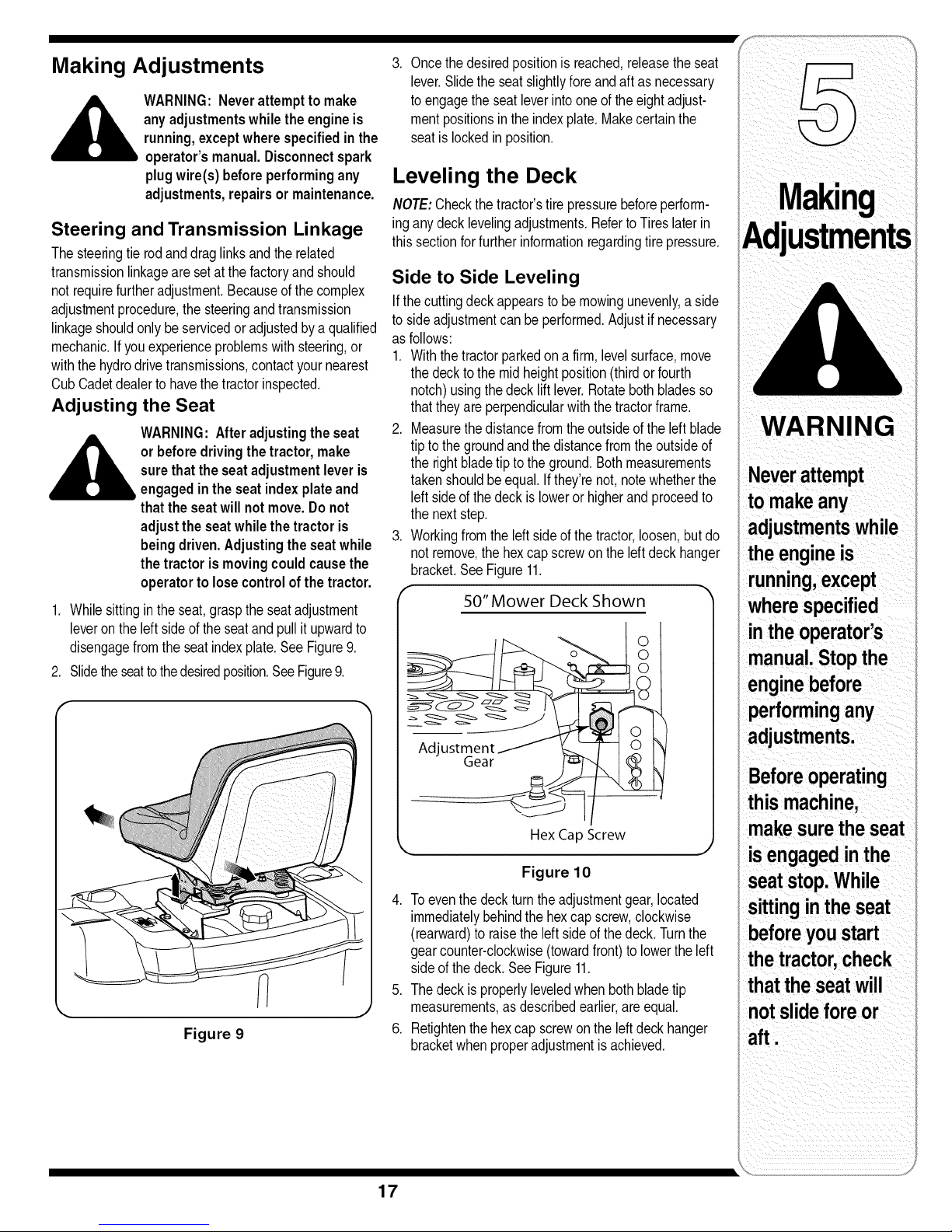
3. Workingfromthe leftsideofthe tractor,loosen,but do
notremove,the hexcap screwontheleft deckhanger
bracket.SeeFigure11.
50" Mower Deck Shown
i
Hex CapScrew
Figure 10
4. Toeventhe deckturntheadjustmentgear,located
immediatelybehindthehexcap screw,clockwise
(rearward)toraisethe leftsideofthedeck.Turnthe
gearcounter-clockwise(towardfront)to lowertheleft
sideof thedeck. SeeFigure11.
5. Thedeckis properlyleveledwhenbothbladetip
measurements,asdescribedearlier,are equal.
6. Retightenthe hexcap screwonthe leftdeckhanger
bracketwhenproperadjustmentis achieved.
WARNING
Neverattempt
tomakeany
adjustmentswhile
theengineis
running,except
wherespecified
intheoperator's
manual.Stopthe
enginebefore
_erformingany
adjustments.
Beforeoperating
this machine,
makesurethe seat
isengagedinthe
seatstop.While
sittinginthe seat
beforeyoustart
thetractor,check
thattheseatwill
notslidefore or
aft.
17
Page 18
Front To Rear Leveling
Thefrontof thecuttingdeckissupportedbyan adjust-
ablefrontdeckhangerrod. Thisrodcanbeadjusted
tosetthe fronttorearpitchofthedeck.The frontofthe
deckshouldbebetween1/4-inchand3/8-inch lowerthan
therearof thedeck.Adjustifnecessaryas follows:
1. Withthetractorparkedon a firm,levelsurface,move
thedeckto themid heightposition(thirdorfourth
notch)usingthe decklift lever.Rotatetheblade
nearestthe dischargechuteso thatit isparallelwith
thetractorframe.
2. Measurethedistancefromthe frontofthe bladetip to
thegroundandthe rearofthe bladetiptothe ground.
Thefrontmeasurementtakenshouldbebetween1/4"
and3/8" lessthan therearmeasurement.Determine
theapproximatedistancenecessaryfor properadjust-
mentand proceed,if necessary,tothe nextstep.
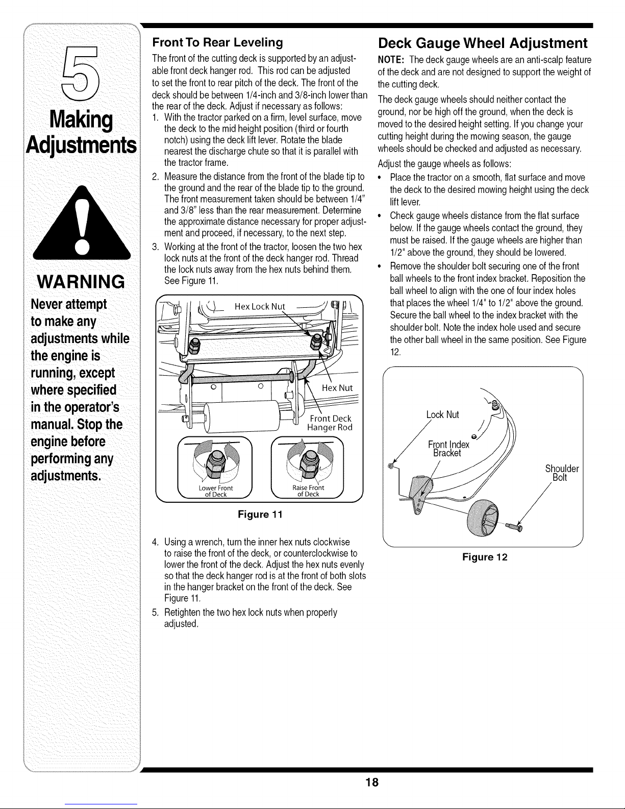
3. Workingatthefrontofthetractor,loosenthetwohex
locknutsatthe frontofthedeckhangerrod.Thread
thelocknutsawayfromthe hexnutsbehindthem.
SeeFigure11.
Deck Gauge Wheel Adjustment
NOTE: The deckgaugewheelsarean anti-scalpfeature
ofthedeckandare notdesignedto supporttheweightof
thecuttingdeck.
Thedeckgaugewheelsshouldneithercontactthe
ground,norbe highoff theground,whenthedeckis
movedto thedesiredheightsetting.If youchangeyour
cuttingheightduringthemowingseason,the gauge
wheelsshouldbecheckedandadjustedas necessary.
Adjustthegaugewheelsas follows:
• Placethetractorona smooth,flatsurfaceandmove
thedeckto thedesiredmowingheightusingthedeck
lift lever.
• Checkgaugewheelsdistancefromtheflat surface
below.Ifthegaugewheelscontactthe ground,they
mustbe raised.Ifthe gaugewheelsarehigherthan
1/2"abovetheground,theyshouldbelowered.
• Removethe shoulderboltsecuringone ofthefront
ballwheelstothe frontindexbracket.Repositionthe
ballwheelto alignwiththeoneoffourindexholes
thatplacesthewheel1/4"to 1/2"abovetheground.
Securetheballwheelto theindexbracketwiththe
shoulderbolt.Notethe indexholeusedandsecure
theother ballwheelinthesameposition.SeeFigure
12.
adjustments.
of Deck _ of Deck j
Raise Front
Figure 11
4. Usinga wrench,turnthe innerhexnutsclockwise
toraisethefrontof thedeck,orcounterclockwiseto
lowerthefrontofthe deck.Adjustthe hexnutsevenly
sothatthe deckhangerrodisatthefrontof bothslots
inthehangerbracketon thefrontof thedeck.See
Figure11.
5. Retightenthe two hexlocknutswhenproperly
adjusted.
LockNut
FrontIndex
Bracket
Shoulder
Bolt
Figure 12
18
Page 19
Deck Rear Roller Adjustment
Therearrollersonthemowerdeckarenotdesignedto
carrytheweightof thedeck,Therearrollersshouldbe
adjustedtoapproximately1/4"to 1/2"abovetheground
whenthe deckis movedtothedesiredcuttingheight,
Placethetractorona smooth,flatsurface,movethe deck
tothe desiredcuttingheight,andcheckthe heightofthe
rearrollers,Ifcontactingthe ground,orabove1/2"from
theground,adjusttherearrollersasfollows:
46" DeckONLY
The46"deck rollerassemblyindexbrackethasthree
adjustmentpositionsusingeitherthebottomtwoholes,
middletwoholes,ortop twoholes.
• Supporttherollerassemblyandremovethetwoself
tappingscrewsfromboththeleftand rightrollerindex
brackets,
• Positiontherollerassemblysothatthe rollersareap-
proximately1/4"to 1/2"abovetheflatsurfacebelow,
Alignthenearesttwoindexbracketholeswithholesin
thedeckmountingbrackets,SeeFigure13,
• Securetherollerassemblywiththefourselftapping
screws.SeeFigure13.
NOTE:Theselftappingscrewsshouldbein the
correspondingholesof boththeleftand rightrollerindex
brackets,
Roller Index Brkt.
0
50"DeckONLY
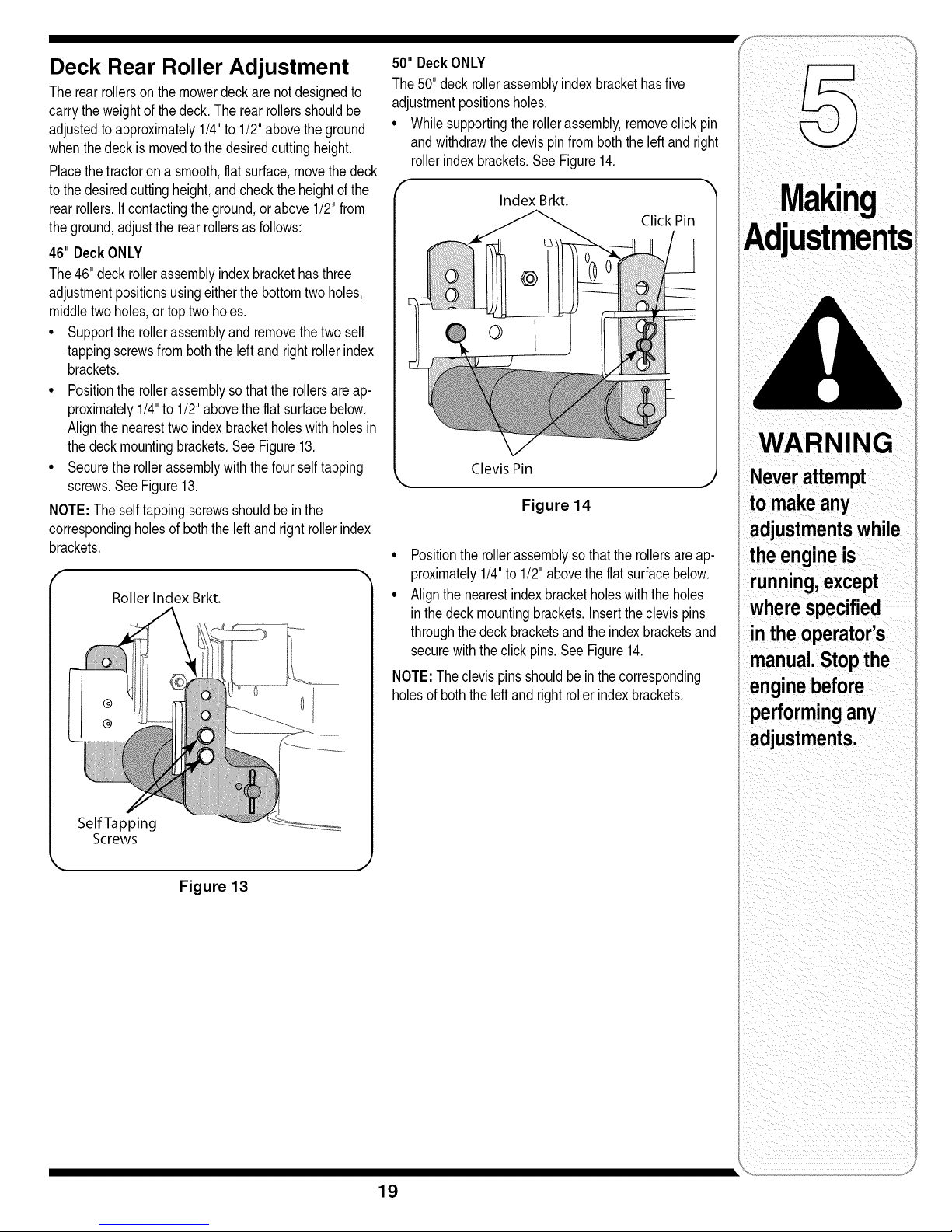
The50" deckrollerassemblyindexbrackethasfive
adjustmentpositionsholes,
• Whilesupportingtherollerassembly,removeclickpin
andwithdrawtheclevispinfromboththeleftand right
rollerindexbrackets,See Figure14,
Index Brkt.
Click Pin
Clevis Pin
Figure 14
• Positionthe rollerassemblysothattherollersareap-
proximately1/4"to 1/2"abovetheflatsurfacebelow.
• Alignthe nearestindexbracketholeswiththeholes
inthedeckmountingbrackets.Inserttheclevispins
throughthedeckbracketsandthe indexbracketsand
securewiththeclick pins.See Figure14.
NOTE:The clevispinsshouldbe inthecorresponding
holesof boththe left andright rollerindexbrackets.
ustments
WARNING
Neverattempt
to makeany
adjustmentswhile
theengineis
running,except
wherespecified
intheoperator's
manual.Stopthe
enginebefore
performingany
adjustments.
Self Tapping
Screws
Figure 13
19
Page 20
Maintaining Your Lawn Tractor
WARNING:Beforeperformingany
maintenanceor repairs,disengage
PTO,setparkingbrake,stopengine
and removekeyto preventunintended
starting.
RecommendedViscosityGrades
ann
nln
WARNING
Before performing
i anymaintenanceor
i repairs,disengage
PTO,moveshift
leverinto neutral
position,set parking
brake,stop engine
and remove keyto
i preventunintended
starting.
Before lubricating,
I repairing,or
i inspecting,always
I
disengagePTO, set
parkingbrake,stop
2engine and remove
keyto prevent
unintendedstarting.
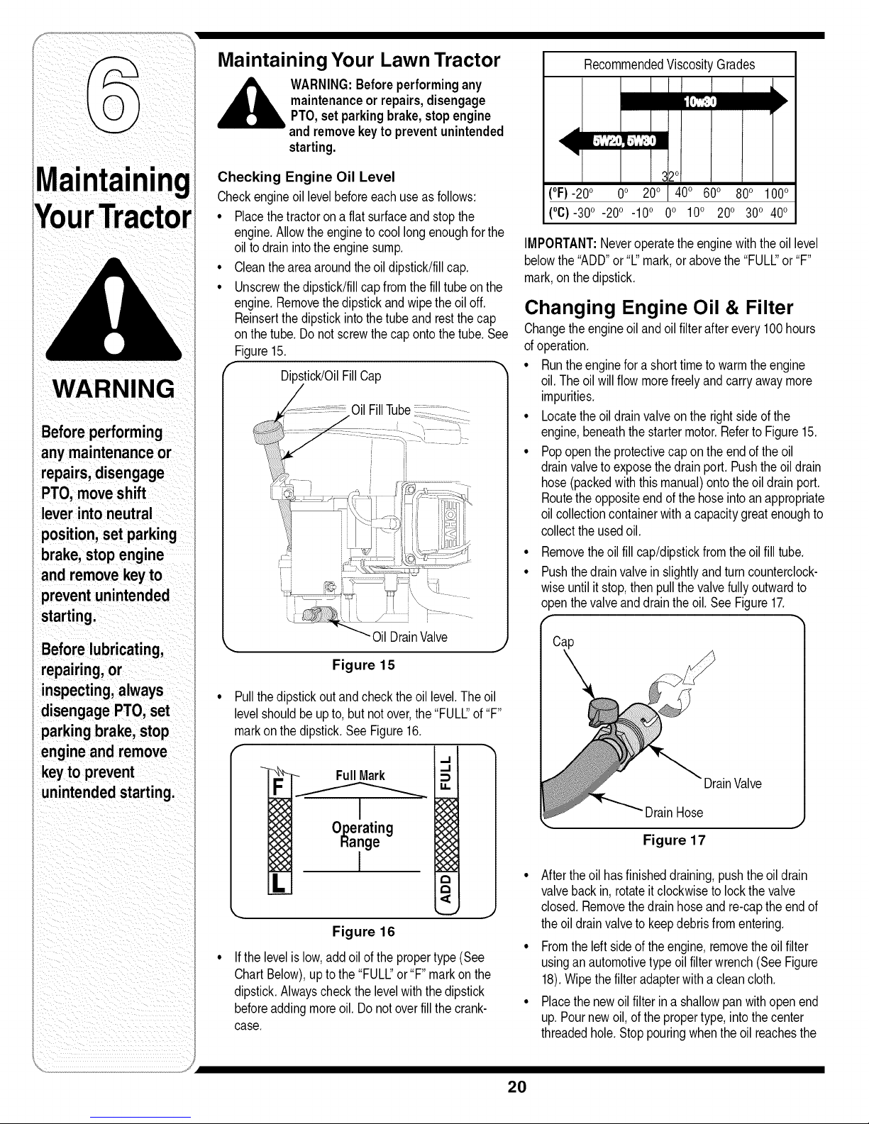
Checking Engine Oil Level
Checkengineoillevelbeforeeachuseas follows:
• Placethetractorona flatsurfaceandstopthe
engine.Allowtheengineto coollongenoughforthe
oilto drainintotheenginesump.
• Cleantheareaaroundtheoildipstick!fillcap.
• Unscrewthedipstick/fillcapfromthefilltube onthe
engine.Removethedipstickandwipethe oiloff.
Reinsertthedipstickintothetubeandrestthe cap
onthetube.Do notscrewthecapontothetube.See
Figure15.
Dipstick/OilFillCap
Oil DrainValve
Figure 15
Pullthedipstickoutandcheckthe oil level.Theoil
levelshouldbeupto, butnotover,the"FULL"of"F'
markon thedipstick.See Figure16.
._1
- FullMark
F
1
_ O_erating
Hange
._1
14.
@
xx
:__o
(°F)-20o 0o 20o 40o 60o 80o 100o
(°C)-30o -20o -10° 0° 10° 20o 30o 40o
IMPORTANT:Neveroperatetheenginewiththeoil level
belowthe"ADD"or"L"mark,orabovethe"FULL"or"F'
mark,onthe dipstick.
Changing Engine Oil & Filter
Changetheengineoiland oilfilterafterevery100hours
ofoperation.
• Runtheenginefora shorttimetowarmtheengine
oil.Theoil willflowmorefreelyandcarryawaymore
impurities.
• Locatetheoildrainvalveon therightsideof the
engine,beneaththe startermotor.Referto Figure15.
• Popopentheprotectivecap ontheendof theoil
drainvalvetoexposethedrainport. Pushtheoil drain
hose(packedwiththismanual)ontotheoil drainport.
Routetheoppositeendof thehoseintoanappropriate
oilcollectioncontainerwitha capacitygreatenoughto
collectthe usedoil.
Removetheoil fillcap/dipstickfromtheoil fill tube.
Pushthedrainvalvein slightlyandturncounterclock-
wiseuntilit stop,thenpullthevalvefullyoutwardto
openthevalveanddrainthe oil.SeeFigure17.
DrainValve
"DrainHose
Figure 17
L_
If thelevelislow,addoilofthe propertype(See
ChartBelow),uptothe "FULl_"or"F" markon the
dipstick.Alwayscheckthe levelwiththedipstick
beforeaddingmoreoil.Donotoverfillthe crank-
case.
Figure 16
Aftertheoil hasfinisheddraining,pushtheoil drain
valvebackin,rotateit clockwisetolockthevalve
J
closed.Removethe drainhoseandre-captheendof
theoildrainvalveto keepdebrisfromentering.
Fromtheleft sideoftheengine,removetheoilfilter
usinganautomotivetypeoil filterwrench(SeeFigure
18).Wipethefilteradapterwitha cleancloth.
Placethe newoilfilterina shallowpanwithopenend
up.Pournewoil,of thepropertype,intothecenter
threadedhole.Stoppouringwhentheoil reachesthe
20
Page 21

bottomof thethreads.Allowa fewminutesforthe oil
to beabsorbedbythefilter material,
AccessDoor
Figure 18
Applya thin coatornewoilon therubbergasketofthe
newoil filter,
• Installthenewoil filteronthefilteradapter.Hand
tightenuntilthe filtergasketcontactsthe adapter,then
tightenthefilteran additional3/4-1 turn.
• Refillthe enginewiththepropertypeoil.Theengine
oil capacityisapproximately1.7-1.9quarts(1.6-1.8L).
Air Cleaner
Checkthe aircleanerbeforeeachuse.Checkfora
buildupofdirt ofdebrisaroundtheair cleanersystem,
Keeptheareaclean,Keepthisareaclean,Also check
forlooseor damagedcomponents,Replaceallbentor
damagedaircleanercomponents,
WARNING:Operatingthe engine with
loose or damagedair cleaner compo-
nents could allow unfiltered air into the
engine causing premature wearand
failure.
Servicing the Precleaner
Washand reoiltheprecleanerevery25 hoursof
operation(moreoftenunderextremelydusty ordirty
conditions),Replacethe precleanerannuallyorevery
100hours,
1. Openthe dooron the blowerhousingto accesstheair
cleanerelementandprecleaner.
2. Unhookthelatchandremovethe precleanerfromthe
air filterelement,SeeFigure19.
NOTE:Theair filterelement/precleanerassemblycan
be removedandthe precleanerthenremovedfromthe
filterelement,Makesurethebaseandthesealingareais
cleanbeforereinstallingthe airfilterelement/precleaner
assembly,
3. Washthe precleanerinwarmwaterwithdetergent,
Rinsetheprecleanerthoroughlyuntilall tracesof
detergentare eliminated.Squeezeout excesswater
(do notwring),Allowtheprecleanertoair dry.
Latch
Precleaner
4. Saturatetheprecleanerwith newengineoil.
Squeezeoutall excessoil.
5. Reinstalltheprecleaneroverthepaperelementand
securewiththelatch.
NOTE:Reinstallthe airfilterelement/precleanerif
removed.
6. Pivotthe latchoverthefilterassemblyandpressthe
latchdownwardto rehook.See Figure19.
IMPORTANT:Makecertainthelatchis securedin the
lockedposition.Failureto properlyhookthelatchwill
allowunfilteredairintotheenginecausingdamageto
theengine.
7. Closethe accessdoor
Filter
Element
Figure 19
Servicing Paper Element
Checkthe paperelementevery50hoursofoperation
(moreoftenif operatedunderextremelydustyordirty
conditions).Cleanor replacetheelementas necessary.
Replacethe air cleanerelementannually,orevery100
hoursof operation.
* Opentheaccessdoor,unhookthelatch,and remove
theairfilterassemblyasdescribedintheprevious
sub-section.
* Removethe precleanerfromthe filterelement.
* Gentlytapthe paperelementtodislodgedirt. Do
notwashthe paperelementor usepressurizedair,
asthiswill damagetheelement.Replacea dirty,
bent,or damagedelement.Do notuseifthesealing
surfacesarebentor damaged.
* Cleantheair cleanerbaseandcheckitscondition.
° Reinstalltheprecleaneroverthepaperair cleaner
elementand installon base.Securewiththelatch
andclosetheaccessdoor.
WARNING
after every100hours
of operation,Failure
prematurewear or
failure ofthe engine,
Operatingthe en-
gine with loose or
damaged air cleaner
components couldal-
low unfilteredair into
the enginecausing
prematurewear and
failure.
21
Page 22
Thissymbolpoints
oUtimportantsafety
instructionswhich,if
notfollowed,could
!
endangerthe personal
safety and/or property
of yourself and others.
Read and follow all
instructions inthis man-
ua beforeattemptng to
operate this machine.
FailuretOcomply with
these instructions
resultinpersonal injury.
when yousee this
symbol
HEED ITS WARNING
Restrictthe use
of this power machine
tOpersonswho read,
i
and follow the warnings
understand
and instructions
in this manual
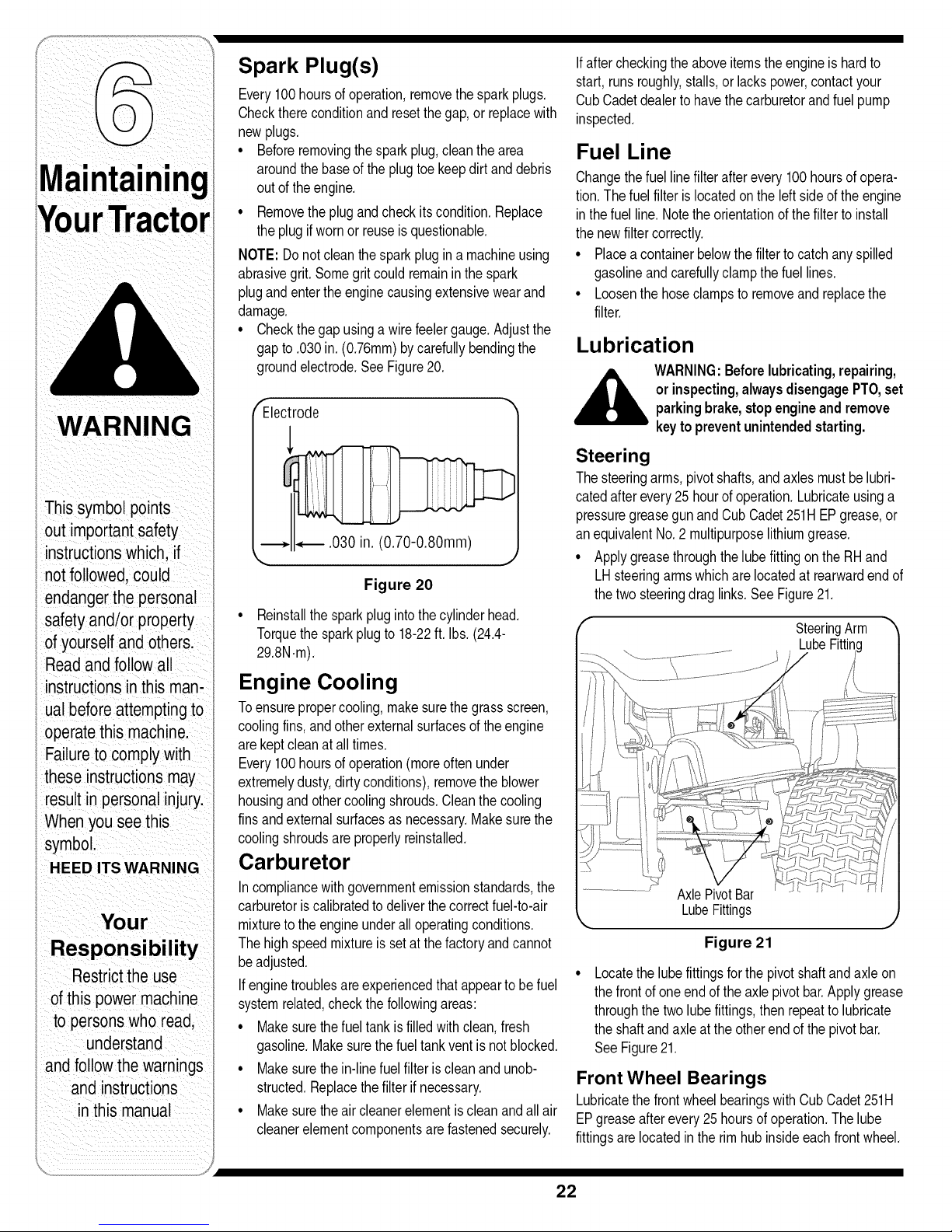
Spark Plug(s)
Every100hoursof operation,removethesparkplugs.
Checkthereconditionand resetthe gap,orreplacewith
newplugs.
• Beforeremovingthesparkplug,cleanthearea
aroundthebaseofthe plugtoekeepdirtanddebris
outof theengine.
• Removetheplugandcheckitscondition.Replace
theplugif wornorreuseisquestionable.
NOTE:Donotcleanthesparkplugin amachineusing
abrasivegrit. Somegritcould remaininthespark
plugandenterthe enginecausingextensivewearand
damage.
• Checkthegap usinga wirefeelergauge.Adjustthe
gapto .030in.(0.76ram)bycarefullybendingthe
groundelectrode.SeeFigure20.
Electrode
, .030 in. (0.70-0.80mm)
J
Figure 20
• Reinstallthesparkplugintothecylinderhead.
Torquethe sparkplugto 18-22ft.Ibs. (24.4-
29.8N.m).
Engine Cooling
Toensurepropercooling,makesurethegrassscreen,
coolingfins,andotherexternalsurfacesof theengine
arekeptcleanat alltimes.
Every100hoursof operation(moreoftenunder
extremelydusty,dirtyconditions),removetheblower
housingandothercoolingshrouds.Cleanthecooling
finsandexternalsurfacesas necessary.Makesurethe
coolingshroudsareproperlyreinstalled.
Carburetor
Incompliancewithgovernmentemissionstandards,the
carburetoris calibratedto deliverthecorrectfuel-to-air
mixturetotheengineunderalloperatingconditions.
Thehighspeedmixtureis setatthefactoryandcannot
beadjusted.
If enginetroublesareexperiencedthatappearto be fuel
systemrelated,checkthefollowingareas:
• Makesurethefueltankisfilledwithclean,fresh
gasoline.Makesurethefueltankventis notblocked.
• Makesurethein-linefuelfilteriscleanand unob-
structed.Replacethefilter ifnecessary.
• Makesuretheair cleanerelementiscleanandallair
cleanerelementcomponentsare fastenedsecurely.
If aftercheckingtheaboveitemstheengineishardto
start,runsroughly,stalls,orlackspower,contactyour
CubCadetdealerto havethecarburetorandfuel pump
inspected.
Fuel Line
Changethefuellinefilterafterevery100hoursofopera-
tion.Thefuel filterislocatedontheleft sideofthe engine
inthefuel line.Notetheorientationofthefilterto install
thenewfiltercorrectly.
• Placeacontainerbelowthefiltertocatchanyspilled
gasolineandcarefullyclampthefuel lines.
• Loosenthehoseclampstoremoveand replacethe
filter.
Lubrication
WARNING:Beforelubricating,repairing,
or inspecting, alwaysdisengagePTO,set
parkingbrake,stopengineandremove
keytopreventunintendedstarting.
Steering
Thesteeringarms,pivotshafts,andaxlesmust belubri-
catedafterevery25 hourofoperation.Lubricateusinga
pressuregreasegunandCubCadet251HEPgrease,or
anequivalentNo.2 multipurposelithiumgrease.
• ApplygreasethroughthelubefittingontheRHand
LHsteeringarmswhichare locatedat rearwardendof
thetwosteeringdraglinks.See Figure21.
SteeringArm
LubeFittin¢
AxlePivotBar
LubeFittings
Figure 21
Locatethelubefittingsfor thepivotshaftandaxleon
thefrontof oneend oftheaxlepivotbar.Applygrease
throughthetwolubefittings,then repeattolubricate
theshaftandaxleat theotherendofthepivotbar.
SeeFigure21.
Front Wheel Bearings
Lubricatethe frontwheelbearingswithCubCadet251H
EPgreaseafterevery25hoursofoperation.Thelube
fittingsare locatedintherimhubinsideeachfrontwheel.
22
Page 23
Deck Spindles
Lubricatethedeck spindlewithCub Cadet251HEP
greaseafterevery10hoursofoperation,
° Thedeckspindlelubefittingsareinthe spindlehous-
ings,andcanonlybe accessedfromtheundersideof
thedeck, Usea pressuregreasegunto lubricatethe
spindles,
• 50" DeckONLY- Lubricatethedeckidlerbracket
every10hoursof operation,The idlerbracketlube
fittingis in theshoulderboltthatsecuresthebracket
tothe deck,
...................
f
iii _i
46" DeckShown
_,_,_ Nozzle
Adapter
Pivot Points & Linkage
Lubricateallthe pivotpointsonthedrivesystem,parking
brakeandlift linkageat leastoncea seasonwithlightoil,
Rear Wheels
Therearwheelsshouldberemovedfromthe axlesonce
a season,Lubricatetheaxlesandthe rimswellwithan
all-purposegreasebeforere-installingthem,
Cleaning the Tractor and Deck
Anyfuelor oil spilledonthemachineshouldbewipedoff
promptly.DoNOTallowdebristo accumulatearoundthe
deckpulleysor anyotherpartofthemachine,
Periodicallyremovethebeltcoversand removeany
accumulatedgrassclippingsfromaroundthespindle
pulleysandthedeckbelt,
IMPORTANT:The useofa pressurewashertocleanyour
tractoris NOTrecommended,It maycausedamageto
electricalcomponents,spindles,pulleys,bearingsorthe
engine,
Deck Wash System TM
Yourtractor'sdeckisequippedwithwaternozzleson its
surfaceas partof itsdeckwashsystem.
UsetheDeckWashSystemTM torinsegrassclippings
fromthedeck'sundersideandpreventthebuildupofcor-
rosivechemicals,CompletethefollowingstepsAFTER
EACHMOWING:
1. Drivethetractorto a level,clearspotonyourlawn,
nearenoughtoa watersillcock(spigot)foryour
gardenhoseto reach,
IMPORTANT:Makecertainthetractor'sdischargechuteis
directedAWAYfromyourhouse,garage,parkedcars,etc,
2, DisengagethePTO(BladeEngage),setthe parking
brake,andstoptheengine,
3, Threadthenozzleadapter(packagedwithyour
tractor'sOperator'sManual)ontotheendof your
gardenhose,
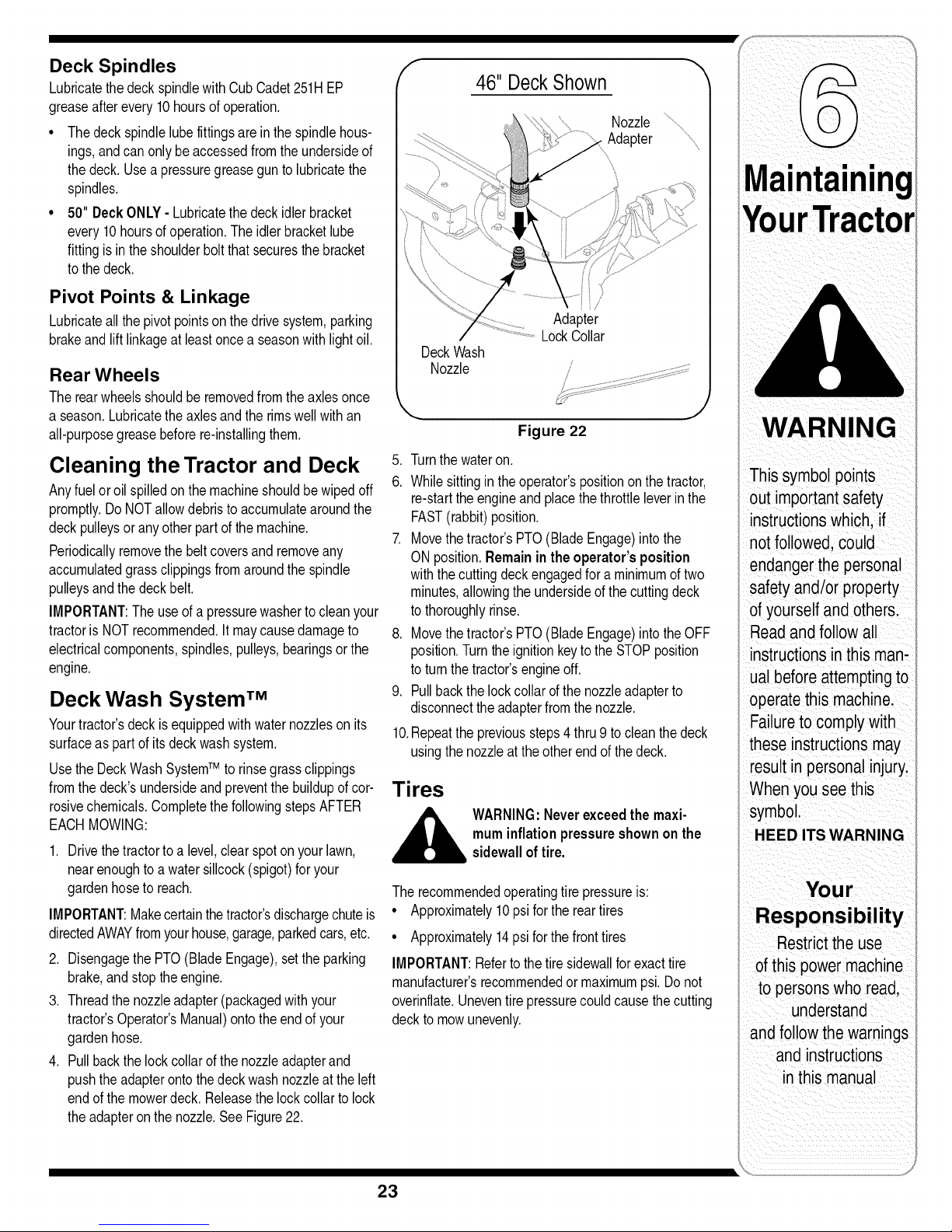
4. Pullbackthe lockcollarofthenozzleadapterand
pushthe adapterontothedeckwashnozzleat theleft
endofthe mowerdeck, Releasethelockcollartolock
theadapteron thenozzle,SeeFigure22,
/
Adapter
LockCollar
DeckWash
Nozzle
Figure 22
,
Turnthewateron.
6,
Whilesittingin theoperator'spositiononthetractor,
re-starttheengineandplacethethrottleleverin the
FAST(rabbit)position.
7. Movethe tractor'sPTO(BladeEngage)intothe
ONposition.Remainin theoperator's position
withthecutting deckengagedfora minimumoftwo
minutes,allowingtheundersideofthe cuttingdeck
tothoroughlyrinse.
8. Movethe tractor'sPTO(BladeEngage)intothe OFF
position.Turntheignitionkeytothe STOPposition
toturnthetractor'sengineoff.
9. Pullbackthelockcollarofthe nozzleadapterto
disconnectthe adapterfromthe nozzle.
10,Repeattheprevioussteps4 thru9 tocleanthedeck
usingthe nozzleattheotherendofthedeck.
Tires
WARNING:Neverexceedthe maxi-
muminflationpressureshownonthe
sidewalloftire.
Therecommendedoperatingtirepressureis:
° Approximately10psiforthereartires
° Approximately14psiforthe fronttires
IMPORTANT:Referto thetire sidewallforexacttire
manufacturer'srecommendedormaximumpsi.Donot
overinflate.Uneventirepressurecouldcausethecutting
decktomowunevenly.
WARNING
Thissymbol points
out importantsafety
instructionswhich, if
notfollowed, could
endangerthe personal
safety and/or property
of yourselfand others.
Readand follow all
instructionsinthis man-
ualbefore attemptingto
operatethis machine.
Failureto comply with
these instructionsmay
resultin personal injury.
When youseethis
symbol.
HEED ITS WARNING
Your
Responsibility
Restrictthe use
ofthis power machine
to personswho read,
understand
andfollow thewarnings
and instructions
in this manual
23
Page 24
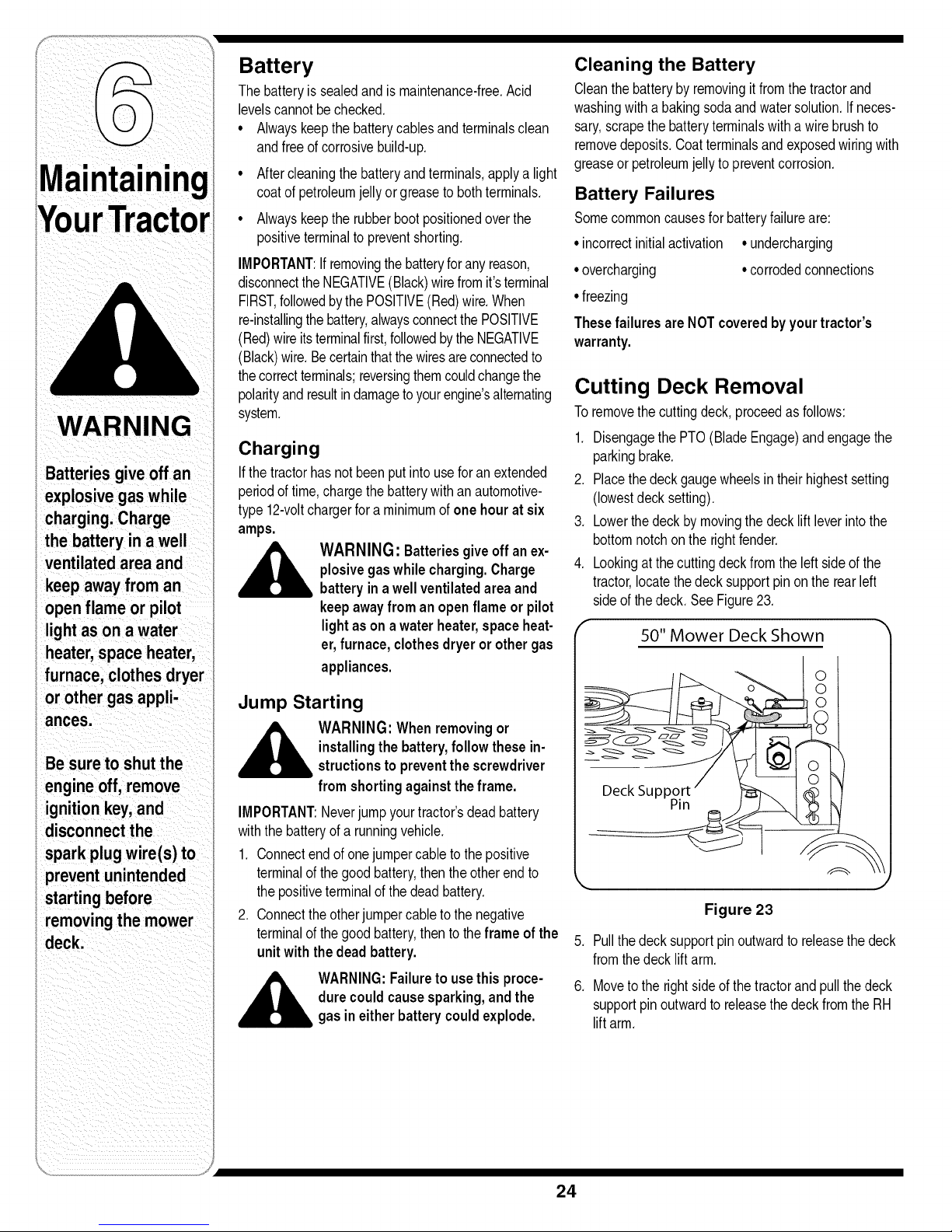
WARNING
Batteries giveoff an
explosivegas while
charging.Charge
i the battery in a well
ventilated area and
i keep awayfrom an
openflame or pilot
lightason a water
i heater,space heater,
furnace, clothes dryer
I or other gasappli-
Iances.
Battery
Thebatteryis sealedandis maintenance-free,Acid
levelscannotbe checked,
° Alwayskeepthebatterycablesandterminalsclean
andfreeof corrosivebuild-up,
Aftercleaningthebatteryandterminals,applya light
coatofpetroleumjellyor greaseto bothterminals.
Alwayskeeptherubberboot positionedoverthe
positiveterminaltopreventshorting,
IMPORTANT:If removingthebatteryforanyreason,
disconnecttheNEGATIVE(Black)wirefromit'sterminal
FIRST,followedbythePOSITIVE(Red)wire,When
re-installingthebattery,alwaysconnectthe POSITIVE
(Red)wireitsterminalfirst,followedbythe NEGATIVE
(Black)wire,Becertainthatthewiresareconnectedto
thecorrectterminals;reversingthemcouldchangethe
polarityandresultindamageto yourengine'salternating
system.
Charging
If thetractorhasnotbeenputintouseforanextended
periodoftime,chargethe batterywithanautomotive-
type 12-voltchargerforaminimumofonehour atsix
amps.
_ ARNING: Batteriesgiveoff anex-
Jump Starting
plosivegaswhile charging.Charge
batteryina wellventilatedareaand
keepawayfrom an open flame orpilot
lightason awaterheater,spaceheat-
er,furnace, clothesdryeror othergas
appliances.
Cleaning the Battery
Cleanthe batterybyremovingit fromthetractorand
washingwitha bakingsodaandwatersolution,If neces-
sary,scrapethe batteryterminalswitha wirebrushto
removedeposits,Coatterminalsandexposedwiringwith
greaseorpetroleumjellyto preventcorrosion,
Battery Failures
Somecommoncausesforbatteryfailureare:
°incorrectinitialactivation °undercharging
°overcharging
*freezing
ThesefailuresareNOTcoveredbyyourtractor's
warranty.
•corrodedconnections
Cutting Deck Removal
Toremovethecuttingdeck, proceedasfollows:
1, DisengagethePTO(BladeEngage)andengagethe
parkingbrake.
2, Placethedeckgaugewheelsintheirhighestsetting
(lowestdecksetting).
3, Lowerthedeckbymovingthedeckliftleverintothe
bottomnotchonthe rightfender.
4, Lookingatthe cuttingdeckfromthe leftsideofthe
tractor,locatethedeck supportpinonthe rearleft
sideof thedeck. SeeFigure23,
50" Mower Deck Shown
i Be sure to shutthe
engineoff,remove
ignitionkey,and
disconnectthe
spark plugwire(s) to
i preventunintended
i starting before
removingthe mower
deck.
__lb ARNING: When removingor
IMPORTANT:Neverjumpyourtractor'sdeadbattery
withthebatteryof arunningvehicle,
1, Connectendofonejumpercabletothepositive
terminalof thegoodbattery,thentheotherendto
thepositiveterminalof thedeadbattery,
2, Connecttheotherjurnpercableto thenegative
terminalof thegoodbattery,thentotheframe of the
unit with the dead battery.
installingthebattery,follow thesein-
structionstopreventthescrewdriver
from shortingagainsttheframe.
WARNING:Failureto usethisproce-
durecouldcausesparking,andthe
gasineither batterycouldexplode.
Figure 23
5, Pullthedeck supportpinoutwardto releasethedeck
fromthedecklift arm,
6, Moveto therightside ofthe tractorandpullthedeck
supportpinoutwardto releasethe deckfromtheRH
lift arm,
24
Page 25
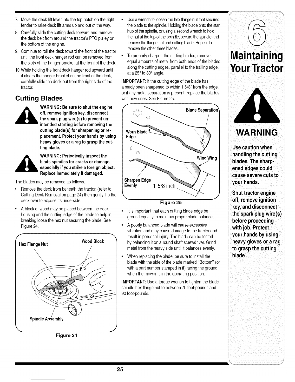
7. Movethedecklift leverintothetopnotchon the right •
fenderto raisedecklift armsupandoutoftheway.
8. Carefullyslidethe cuttingdeckforwardandremove
thedeckbelt fromaroundthetractor'sPTOpulleyon
thebottomofthe engine.
9. Continueto rollthedecktowardthefrontof thetractor
untilthe frontdeckhangerrodcanberemovedfrom °
theslotsofthe hangerbracketat thefrontof thedeck.
10.Whileholdingthe frontdeckhangerrodupwarduntil
it clearsthe hangerbracketonthefrontofthedeck,
carefullyslidethedeckout fromtherightsideofthe
tractor.
Cutting
A
Thebladesmaybe removedas follows.
• Removethe deckfrombeneaththetractor,(referto
CuttingDeck Removalonpage24)thengentlyflipthe
deckoverto exposeits underside.
A blockofwoodmaybeplacedbetweenthedeck
housingandthe cuttingedgeof thebladetohelpin
breakingloosethehex nutsecuringtheblade.See
Figure24.
('I"- WoodBlock
HexFlangeNut
Blades
WARNING:Be suretoshuttheengine
off,removeignition key,disconnect
thesparkplugwire(s) to preventun-
intendedstartingbeforeremovingthe
cuttingblade(s)for sharpeningor re-
placement.Protectyourhandsbyusing
heavyglovesor a ragto graspthecut-
tingblade.
WARNING:Periodicallyinspect the
bladespindlesfor cracksordamage,
especiallyif youstrikea foreign object.
Replaceimmediatelyifdamaged.
Useawrenchto loosenthehexflangenutthatsecures
thebladetothespindle.Holdingthebladeontothestar
hubofthespindle,orusinga secondwrenchto hold
thenutatthetopof thespindle,securethe spindleand
removetheflangenutandcuttingblade.Repeatto
removetheotherthreeblades.
Toproperlysharpenthecuttingblades,remove
equalamountsof metalfrombothendsoftheblades
alongthecuttingedges,paralleltothe trailingedge,
ata 25oto30oangle.
IMPORTANT:Ifthecuttingedgeof thebladehas
alreadybeensharpenedto within 15/8"fromthe edge,
or ifanymetalseparationispresent,replacetheblades
withnewones.SeeFigure25.
WindWing
Figure 25
• It is importantthateachcuttingbladeedgebe
groundequallyto maintainproperbladebalance.
A poorlybalancedbladewillcauseexcessive
vibrationand maycausedamagetothetractorand
resultinpersonalinjury.Thebladecanbetested
bybalancingitona roundshaftscrewdriver.Grind
metalfromtheheavyside untilit balancesevenly.
• Whenreplacingtheblade,be suretoinstallthe
bladewiththeside oftheblademarked"Bottom"(or
witha partnumberstampedinit) facingtheground
whenthe mowerisintheoperatingposition.
IMPORTANT:Usea torquewrenchtotightentheblade
spindlehexflangenutto between70foot-poundsand
90foot-pounds.
WARNING
Usecaution when
handlingthe cutting
blades.The sharp-
ened edges could
cause severe cutsto
your hands.
Shut tractor engine
off, remove ignition
key,and disconnect
the spark plug wire(s)
before proceeding
with job. Protect
your hands by using
heavygloves or a rag
to graspthe cutting
blade
SpindleAssembly
k,,.. j
Figure 24
25
Page 26

11
IMPORTANT
IMPORTANT: Always
usea fuse withthe
same amperagecapac-
ityfor replacement.
Fuses •
• A 20ampfuseis installedin yourtractor'swiring
harnesstoprotectthetractor'selectricalsystemfrom
damagecausedbyexcessiveamperage. •
• If the electricalsystemdoes notfunction,oryour
tractor'senginewillnot crank,firstcheckto be
certainthatthefusehas notblown, •
Thefusecan befoundinsideofthedashpanel
behindthebatterytray.Youmayneedto removethe
batteryto gainaccesstothefuse.
A fiveampfusecanalsobefoundinsidethedash
panel,Thisfuse is forthe 12voltpoweroutlet,
Alwaysuse a fusewiththesameamperagecapacity
for replacement.
Changing TransmissionDriveBelt
NOTE:Severalcomponentsmustberemoved,includ-
ingtransmissionsteeringlinkagewhichwillhavetobe
readjusted,inorderto changethetractor'stransmission
drivebelt,ContactyourCubCadetdealertohaveyour
transmissiondrivebeltreplaced,
Hydrostatic Transmission
Keeptheareaaroundthetransmissioncoolingfan
freeof grassanddebrisatalltimes,Thehydrostatic
transmissionissealedat thefactoryandismaintenance
free,Thefluid levelcannotbecheckedandcannotbe
changed,
Changing the Deck Belt
WARNING: Besuretoshutthe engine
off, removeignition key,disconnect
the spark plugwire(s) to prevent
unintended starting before removing
thebelt(s).
WARNING:Avoidthepossibility of
a pinching injury. Donot place your
fingers on the idlerspringor between
thebeltanda pulleywhileremoving
thebelt.
Allbeltson yourtractoraresubjecttowearandshould
be replacedif anysignsofweararepresent,
IMPORTANT:Donotusesubstitutebelts.TheV-belt
foundonyourtractoris speciallydesignedfor optimal
performanceandservicelifeforyourdeckapplication.
UseonlyOEMoriginalreplacementbelts.
Tochangeor replacethedeckbeltonyourtractor,
proceedasfollows:
• Removethedeckfrombeneaththetractor(referto
CuttingDeckRemovalon page24)
Removethespindlecoversbyremovingtheself-tap-
pingscrewsthat fastenthemtothe deck,SeeFigure
26.
46"Mower DeckONLY- Removetheoldbeltfrom
thedeck,Installthe newbeltaroundthespindleand
idlerpulleysas shownin Figure27.
50"MowerDeckONLY
1. Loosenthehexscrewfasteningtheidlerpulley
tothe idlerarmasnecessaryto slidethebelt
frombetweenthe idlerpulleyandidlerarm,See
Figure26.
SpindleCover
dler Pulley
Figure 26
2, Placethe newbeltbetweentheidlerpulleyand
idlerarm,Thebacksideofthe 'V' beltshouldbe
againsttheidlerpulley,Tightenthehexscrewto
securetheidlerpulley,
3, Routethedeckbeltaroundthespindlepulleys
andidlerpulleysasshownin Figure28,
Reinstallthespindlecoversonthedeckusingthe
self-tappingscrews.Donotovertightenthe screws.
Reinstalling the Cutting Deck
Therearetwomethodsforreinstallingthemowerdeckon
thetractor,Onemethodinvolvesrotatingthedeckidler
armto relieveenoughbelttensiontoallowthebelt tobe
placedineitherthePTOpulleyora deckpulley,Because
thatmethodisdifficult,werecommendusingthesecond
methodofrollingthe beltontothePTOpulley.
Installthe cuttingdeckas follows:
• Fromtherightside ofthe tractor,slidethedeck under
thetractorandalignthereaddeckhangerbracket
withthedeckliftarms.
Slidethedeckforwardandplacethedeckfront
hangerrodintothe slotsof thedeckfronthanger
bracket.Then slidethe deckrearwardsothatthe
hangerrodisat thefrontoftheslots.
Usingthedecklift lever,lowerthe decklift arms.From
eithersideofthe tractor,pullthesupportpininthe
deckrearhangerbracketoutward,alignthe decklift
armholewiththe decksupportpinand releasethepin
sothatit goesthroughthedeckliftarm.Repeatonthe
othersideofthe tractortosecurethedeck.
26
Page 27
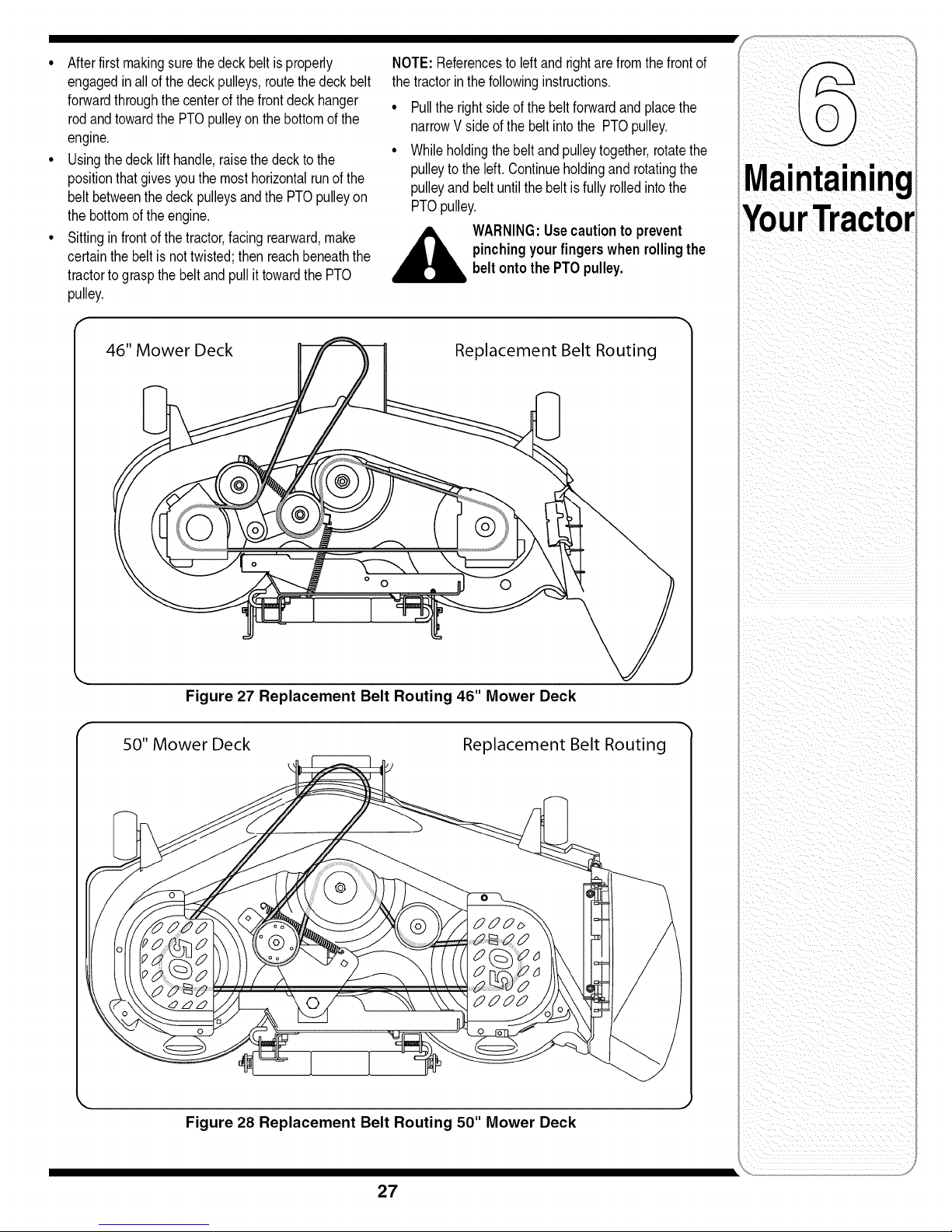
• Afterfirstmakingsurethe deckbeltis properly
engagedinall ofthedeckpulleys,routethedeckbelt
forwardthroughthecenterofthe frontdeckhanger
rodandtowardthe PTOpulleyonthebottomofthe
engine,
• Usingthedeck lifthandle,raisethedeckto the
positionthatgivesyouthe mosthorizontalrunofthe
beltbetweenthedeckpulleysandthePTOpulleyon
thebottomofthe engine.
• Sittingin frontof thetractor,facingrearward,make
certainthebeltis nottwisted;thenreachbeneaththe
tractorto graspthe beltandpullittowardthe PTO
pulley,
NOTE:Referencestoleftand rightarefromthefrontof
thetractorinthefollowinginstructions,
• Pulltherightside ofthebeltforwardandplacethe
narrowVsideofthe beltintothe PTOpulley,
• Whileholdingthebeltandpulleytogether,rotatethe
pulleyto theleft. Continueholdingandrotatingthe
pulleyandbeltuntilthe beltisfully rolledintothe
PTOpulley,
,__ WARNING:Usecautionto prevent
pinchingyourfingers whenrollingthe
beltontothe PTOpulley.
II
46" Mower Deck
Figure 27 Replacement Belt Routing 46" Mower Deck
50" Mower Deck
Replacement Belt Routing
i i i i i i ii
ii i _iI_ ii
Replacement Belt Routing
k.
Figure 28 Replacement Belt Routing 50" Mower Deck
27
Page 28
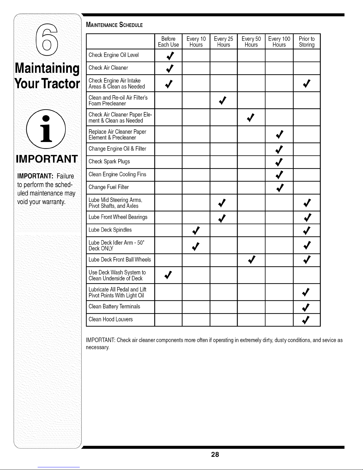
MAINTENANCESCHEDULE
EachUse Hours Hours Hours Hours Storing
CheckEngineOilLevel 4
Before Every10 Every25 Every50 Every100 Priorto
,alnln
]1.
IMPORTANT
IMPORTANT: Failure
to performthe sched-
uledmaintenancemay
voidyour warranty.
CheckAirCleaner _'
CheckEngineAirIntake
Areas& Cleanas Needed _' _'
CleanandRe-oilAir Filter's
FoamPrecleaner _'
CheckAirCleanerPaperEle-
ment& CleanasNeeded _'
ReplaceAir CleanerPaper
Element& Precleaner _'
ChangeEngineOil& Filter 4
CheckSparkPlugs _'
CleanEngineCoolingFins 4
ChangeFuelFilter _'
LubeMidSteeringArms,
PivotShafts,andAxles 4 _'
LubeFrontWheelBearings 4 _
LubeDeckSpindles ,_ _'
LubeDeckIdlerArm- 50"
DeckONLY 4 _1_
LubeDeckFrontBallWheels _' 4
UseDeckWashSystemto _,
CleanUndersideof Deck
LubricateAll PedalandLift _,
PivotPointsWith LightOil
CleanBatteryTerminals ,_
CleanHoodLouvers 4
IMPORTANT:Checkair cleanercomponentsmoreoftenif operatinginextremelydirty,dustyconditions,andseviceas
necessary.
28
Page 29
If themachineistobeinoperativefora periodlongerthan
30days,the followingproceduresare recommended:
WARNING:Neverstorethe machineor
fuelcontainerindoors wherethereis an
openflame, sparkor pilotlightsuchas
onwaterheater,furnace, clothesdryer
orothergas appliance.
IMPORTANT:Fuelleftin the fueltankduringwarm
weatherdeterioratesandwill causeseriousstarting
problems,
Topreventgumdepositsfromforminginsidethe
engine'scarburetorandcausingpossiblemalfunctionof
theengine,thefuelsystemmustbeeithercompletely
emptied,orthe gasolinemustbetreatedwitha stabilizer
topreventdeterioration,
1, If usingafuelstabilizer:
• Readtheproductmanufacturer'sinstructionsand
recommendations,
• Addtoclean,freshgasolinethecorrectamount
ofstabizerforthecapacityofthefuelsystem,
° Fillthefueltankwithtreatedfueland runthe
enginefor2-3minutestoget stabilizedfuelinto
thecarburetor.
2, If emptyingthefuel system:
• Donotdrainfuelwhentheengineis hot,Allow
theengineadequatetimeto cool, Drainfuelinto
anapprovedcontaineroutdoors,awayfromopen
flame,
• Drainanylargevolumeoffuelfromthetankby
disconnectingthefuellinefromthe in-linefuel
filterneartheengine,
° Reconnectthefuellineand runtheengineuntil
itstartsto falter,thenusethechoketo keepthe
enginerunninguntilall fuel inthecarburetor
hasbeenexhausted,
• Againdisconnectthefuellineanddrainany
remaininggasolinefromthe system,
,_ WARNING:Drainfuelonly into an
Removethesparkplugandpourone (1)ounceof
engineoilthroughthe sparkplugholeintothe cylinder,
Cranktheengineseveraltimestodistributetheoil,
Replacethe sparkplug,
Cleanandlubricatethetractoras instructedin Section
6: MAINTAININGYOURLAWNTRACTORof this
manualbeforestoringforanextendedperiod,
approvedcontaineroutdoors,away
from anopenflame.Allowengineto
cool.Extinguishcigarettes,cigars,
pipes,andothersourcesof ignition
priorto drainingfuel.
Attachments & Accessories
ThefollowingattachmentsandaccessoriesareavailalbefortheModeli1046and/ori1050LawnTractors,Seethe
retailerfromwhichyoupurchasedyourtractor,oran authorizedCubCadetDealerfor informationregardingprice
andavailability,
WARNING
Drainfuel only intoan
approved container
outdoors,away
from an open flame.
Allowengine to cool.
Extinguishcigarettes,
cigars, pipes, and
other sources
of ignitionpriorto
drainingfuel.
MODEL' DESCRIPTION
19A-100-100 TwinRearBaggerGrassCollectorfor46" Deck
19A'101-100 TwinRearBaggerGrassColleCtorfor 50"DeCk
190-833-000 46" DozerBlade
Neverstore the
machineor fuel
container indoors
where there isan
open flame, spark or
pilotlightsuchas on
water heater,furnace,
clothes dryer or other
gasappliance.
29
Page 30

WARNING
Warning/Instruction Label-
On Center of Fender Running Board
Thissymbolpoints
outimportantsafety
instructionswhich,if
notfollowed,could
endangerthe personal
i safetyand/or property
i ofyourselfand others.
Readandfollowall
instructionsinthis
manualbeforeat-
temptingto operate
this machine.Failure
to complywiththese
i instructionsmayresult
i inpersonalinjury.When
youseethis symbol.
i HEED ITS WARNING!
Your Responsibility
Restrictthe use
ofthis power machine
to personswho read,
understand
andfollowthe warnings
and instructions
i inthis manual
and onthe machine.
Warning-
On Steering Gears
Danger-
OnDeckChuteDeflector
46" DeckONLY
Danger- On Left Side of Deck
Warning-
OnHitch Plate
Danger-
On RightSide of Deck
................................i/+..I
+ 1121 / _1 _:{*] d _:l d W:Td I
ASSEMBLECHUTEDEFLECTORTO THIS UNIT BEFOREOPERATING.I
50" DeckONLY
Danger- On Left Side of Deck
30
Page 31

Problem Cause Remedy
Engine fails to statr 1• PTOengaged• 1• PacePTO.knobnd sengaged
(OFF)position.
2. Sparkplugwire(s)disconnected. 2• Connectwire(s)tosparkplug(s).
3 Fueltankemptyorstalefuel 3• Filltankwithclean,freshgasoline•
4• Chokenotactivated• 4• Pulloutthe CHOKEcontrol(ifso
equipped)orplacethe throttle
controlinCHOKEposition,
5. Faultysparkplug. 5. Clean,adjustgap,or replace•
6• Blockedfuel l ne• 6 C eanfue neor repacefue f ter
7 Engnef ooded if so e uipped
• . q .
7• Crankenginewiththrottlein FAST
9• Throttlecontrollevernotin correct 9• PlacethrottlelevertoFAST
startingposition• position•
Engineruns erratic
1. UnitrunningwithCHOKEapplied.
2. Sparkplugwire(s)loose.
3. Blockedfuellineor stalefuel.
4. Ventingascapplugged.
5. Waterordirt infuel system.
6. Dirty aircleaner.
1. PushCHOKEcontrolin.
2. Connectandtightenspark
plugwire(s).
3. Cleanfuelline;filltankwithclean,
fresh(lessthan30 daysold)
gasoline.Replacefuel filter,if so
equipped.
4. Clearventor replaceifdamaged.
5. Drainfueltank. Refillwith
freshfuel.
6. Replaceaircleanercartridge/ele-
mentorcleanpre-cleaner,if so
equipped.
Trouble
Shooting
Forrepairsbeyond
theminoradjust-
ments/istedhere,
contact an authorized
31
Page 32

I _ i
i i_i_i_Iiii
i_ I _ii _ _ _i_i_ _ _ i_i_i i
contact an authorized
servicedealer.
,2. Air flowrestricted. 2. Cleangrassclippingsanddebris
' fromaroundtheengine'scooling
t finsandblowerhousing.
Enginehesitatesat 1. Sparkplug(s)gap tooclose. 1. Removesparkplug(s)and reset
high RPM thegap.
des poor\/ 1. Sparkplug(s)fouled faultyorgap 1. Replacesparkplug(s).Set plug(s)
] I
toowide. gap.
2. Dirtyair cleaner. 2. Replaceair cleanercartridge/ele-
Excessive 1. Cuttingbladelooseorunbalanced. 1. Tightenbladeandspindle.Balance
Vibration blade.
2. Damagedor bentcutting blade. 2. Replaceblade.
Mowerwil not 1. Enginespeedtoolow 1. Placethrottlecontrolin FAST
mulch grass (If . g
Eqppuied) 2. Do notmowwnengrass s wet
Unevencut 1. Decknotbalancedproperly.
2 Wet rass (rabbt)poston
wat unt aterto cut
3. Excessivelyhighgrass.
3. Mowonce ata highcuttingheight,
thenmowagainat desiredheight
I ormakea narrowercuttingpath.
4. Dullblade.
2. Dullblade.
3. Uneventirepressure.
4. Sharpenorreplaceblade.
1. Performside-to-sidedeckadjust-
ment.
2. Sharpenorreplaceblade.
3. Checktirepressureinall fourtires.
i_ _iiiii_ i I
32
Page 33

NOTE:ContactyourCubCadetdealerto orderreplacementparts.Ifyou donothaveadealer,
callthe CustomerDealerReferralLineat 1-877-282-8684or visitwww.cubcadet.comto find
thenearestCubCadetdealerinyourarea.
Description Model i1046
LowerDriveBelt- ContactDeaier ...........................954-04134
Engineto Deck!DeckSpindleBelt 954-04118
DeckBlades-46i, Deck' 942-04124(Qty.1)
DeckSpindle 618-0660(Qty.3)
DeckFrontBallWheels 734-04155(Qty.2) 734-04155 (Qty.2)
DeckRearGaugeWheels 734-0973(Qty.2)
DeckRollers -731-3005 (Qtyl3)731-3005 (Qtyl4)
Battery 925-1707D 925-1707D
StarterSolenoid 725:04439- 725:04439
IgnitionKeys 725-2054 725-2054
EngineOil Filter KH-52'050'02 KH-52-050-02
EngineOil (Capacity57.6ounces) 737-3030A(lqt.) 737-3030A(lqt.)
EngineAir FilterElernent- KH-32-083'03-S KH-32-083-03-S
EngineAir FilterFoamPrecleanerElement KH-32-083-05-S KH-32-083-05-S
FuelFilter -KH-25-050:22-S KH-25:050'22-S
SparkPlug 759-3336 759-3336
DeckDischargechute AsSembly 931q032B ' 631:04070A
I |
Model i1050
954-04134
954-04077
942,04053A(etyl 3)
618-04126(Qty.3)
i i _i i _ ii _
Toorder replacement
parts, call the Customer
Dealer Referral Line at
1-877-282-8684,
or visit
www.cubcadet.comto
find the nearestCub
Cadetservice dealer in
your area.
WARNING:If a safetyfeatureisnotfunctioningproperly,do notusethe tractor.Contactyou Cub
CadetDealerorcall (800)965-4CUB.
33
Page 34

KOHLERCO.
FEDERALAND CALIFORNIAEMISSIONCONTROLSYSTEMS
LIMITEDWARRANTY
UTILITYAND LAWNANDGARDENENGINES
The U.S.Environmental ProtectionAgency (EPA), the California Air Resources Board (CARB), and Kohler Co.are pleasedto explain the Federaland California Emission
ControlSystems Warrantyon yoursmall off-road equipment engine. For California, enginesproduced in 1995and later must be designed, built and equipped to meetthe
state'sstringent anti-smog standards.Inother states, 1997and latermodel year engines must be designed, built andequipped, to meetthe U.S.EPAregulationsfor small
non-roadengines.The engine must be free from defects in materials and workmanship which cause it to failto conform with U.S.EPA standards for thefirst two years of
engine use fromthe date of saleto the ultimate purchaser.Kohler Co. mustwarrant the emission control system on the engine forthe periodof time listed above,provided
there has been no abuse, neglector improper maintenance.
The emissioncontrol system may include parts suchas thecarburetor orfuel injection system, theignition system, and catalytic converter.Also includedare the hoses,
belts and connectors and otheremission relatedassemblies.
Wherea warrantablecondition exists,Kohler Co. will repairthe engine at nocost, including diagnosis (ifthe diagnostic work is performed at an authorized dealer), parts
and labor.
MANUFACTURER'S WARRANTY COVERAGE
Engines produced in 1995 or laterare warranted for two years inCalifornia. Inother states, 1997and latermodelyear enginesare warranted for twoyears, if any emission
related part on the engine is defective,thepart will be repairedor replacedby Kohler Co.free of charge.
OWNER'S WARRANTY RESPONSIBILITIES
(a) The engine owner is responsible for the performance of the required maintenance listed in the owner's manual. Kehler Co. recommends that you retain all receipts
covering maintenance on the engine. But Kohler Co. cannot deny warranty solely for the lack of receipts or for your failure to assure that all scheduled maintenance
was performed.
(b) Be aware, however,that Kehler Co. maydeny warranty coverage if the engine or apart has failed due to abuse, neglect, improper maintenance or unapproved
modifications.
(c) For warranty repairs, the engine must be presented to a Kohler Co. service center as soon as a problem exists. Call 1-800-544-2444, or access our web siteat:
www.kohlerengines.com, for the names of the nearest service centers. The warranty repairs should be completed in a reasonable amount of time, not to exceed30
days.
Ifyou haveany questions regardingwarranty rights and responsibilities,you should contact Kohler Co.at 1-920-457-4441 and askfor an Engine Service representative.
COVERAGE
Kohler Co.warrants to the ultimate purchaser and each subsequent purchaser that the engine will be designed, builtand equipped, at the time ofsale, to meet all appli-
cable regulations.KohlerCo.also warrants to the initial purchaser andeach subsequent purchaser,that the engine isfree from defects inmaterial andworkmanship which
causethe engine to failto conform with applicable regulationsfor a periodof two years.
Engines produced in 1995 or laterare warranted for two years inCalifornia. For1997 and later model years, EPArequires manufacturersto warrant enginesfor twoyears in
all other states.These warranty periodswill be begin on thedate theengine is purchased bythe initialpurchaser. Ifany emission related part on theengine is defective,the
part will be replacedby Kohler Co. at nocost to theowner.Kohler Co.is liable for damages to other engine components caused bythe failureof a warranted part still under
warranty.
Kohler Co.shall remedywarranty defectsat any authorized KohlerCo.engine dealer orwarranty station.Warranty repairwork done at an authorizeddealer orwarranty
stationshall befree of chargeto the owner if suchworkdetermines that a warranted part is defective.
Listedbelow are the parts coveredby the Federal and California Emission Control Systems Warranty.Some parts listed below may requirescheduled maintenance and are
warranted upto the first scheduled replacement point for that part.The warranted parts are:
• Oxygen sensor (if equipped)
• Intake manifold (if equipped)
• Exhaust manifold (ifequipped)
• Catalytic muffler (if equipped)
• Fuel metering valve (ifequipped)
" Spark advance module (if equipped)
LIMITATIONS
This Emission Control SystemWarrantyshall not cover any of the following:
(a) repair or replacement required because of misuse or neglect, improper maintenance, repairs improperly performed or replacements not conforming to Kohler Co.
specifications that adversely affect performance and/or durability and alterations or modifications not recommended or approved in writing by Kohler Co.,
(b) replacement of parts andother services and adjustments necessary for required maintenance atand after the first scheduled replacement point,
(c) consequential damages such as loss of time, inconvenience, lossof use of the engine or equipment, etc.,
(d) diagnosis and inspection fees that do not result in eligible warranty service being performed, and(e)any add-on or modified part, or malfunction of authorized parts
due to the use ofadd-on or modified parts.
MAINTENANCE AND REPAIRS REQUIREMENTS
The owner is responsiblefor the proper use and maintenance of the engine. KohlerCo. recommends thatall receipts and records covering the performance of regular
maintenance be retained in casequestions arise. If the engine is resold during the warranty period, the maintenance recordsshould be transferred to each subsequent
owner.KohlerCo.reserves the rightto deny warranty coverage ifthe engine has notbeen properly maintained; however,KohlerCo.may not denywarranty repairssolely
because of the lack of repairmaintenance or failure to keep maintenance records.
Normal maintenance, replacementor repairof emission control devices and systems maybe performed by any repair establishmentor individual;however,warranty repair
must be performedby a Kohler authorized service center.Any replacement part or service that is equivalent inperformance and durability maybe used in non-warranty
maintenance or repairs, andshall not reducethe warranty obligations ofthe engine manufacturer.
• Ignition module(s) with high tension lead
• Gaseous fuel regulator (if equipped)
• Electronic control unit (ifequipped)
• Carburetor or fuel injection system
• Fuel lines (if equipped)
" Air filter, fuel filter, and spark plugs (only to first scheduled replacement point)
Page 35

CALIFORNIA EMISSION CONTROL WARRANTY STATEMENT
YOUR WARRANTY RIGHTS AND OBLIGATIONS
TheCaliforniaAir ResourcesBoardandMTDConsumerGroup Incarepleasedtoexplainthe evaporativeemissioncontrolsystemwarrantyon your2007lawn
mower.InCalifornia,newlawnmowermustbedesigned,builtand equippedto meetthe State'sstringentanti-smogstandards.MTDConsumerGroupInc must
warrantthe EECSonyourlawnmowerforthe periodof time listedbelowprovidedtherehas beennoabuse,neglector impropermaintenanceof yourlawn mower.
YourEECSmayincludepartssuchas the carburetor,fuel-injectionsystem,the ignitionsystem,catalyticconverter,fueltanks,fuel lines,fuelcaps,valves,
canisters,filters,vaporhoses,clamps,connectors,andotherassociatedemission-relatedcomponents.
Wherea warrantable condition exists, MTDConsumer Group Incwill repair your lawn mower at no cost toyou including diagnosis, parts and labor.
MANUFACTURER'S WARRANTY COVERAGE:
Thisevaporativeemissioncontrolsystemiswarrantedfortwo years.If anyevaporativeemission-relatedpartonyourequipmentisdefective,the partwill be
repairedorreplacedbyMTDConsumerGroupInc.
OWNER'S WARRANTY RESPONSIBILITIES:
Asthelawnmowerowner,youare responsiblefor performanceoftherequiredmaintenancelistedin yourowner'smanual. MTDConsumerGroup Increcom-
mendsthatyou retainall receiptscoveringmaintenanceon yourlawnmower,butMTDConsumerGroupInccannotdenywarrantysolelyforthe lackof receipts.
Asthelawnmowerowner,youshould howeverbeawarethat MTDConsumerGroupInc maydenyyou warrantycoverageifyour lawnmowerora parthasfailed
duetoabuse,neglect,or impropermaintenanceor unapprovedmodifications.
Youareresponsibleforpresentingyourlawnmowerto MTDConsumerGroupInc'sdistributioncenterorservicecenteras soonas theproblemexists.The
warrantyrepairsshouldbecompletedin a reasonableamountoftime,notto exceed30 days.Ifyou havea questionregardingyourwarrantycoverage,youshould
contacttheMTDConsumerGroupIncServiceDepartmentat1-800-800-7310.
GENERAL EMISSIONS WARRANTY COVERAGE:
MTDConsumerGroupIncwarrantstothe ultimatepurchaserandeachsubsequentpurchaserthatthelawnmoweris: Designed,builtandequippedso as to
conformwithall applicableregulations;andfreefromdefects in materialsandworkmanshipthat causethefailureofa warrantedpartto beidenticalinall material
respectstothat partas describedin MTDConsumerGroupInc'sapplicationforcertification.
Thewarrantyperiodbeginsonthe datethe lawn mowerisdeliveredto an ultimatepurchaseror first placedintoservice.Thewarrantyperiod istwo years.
Subjectto certainconditionsandexclusionsas statedbelow,thewarrantyon emission-relatedpartsis asfollows:
1. Anywarrantedpartthat is notscheduledfor replacementas requiredmaintenancein the writteninstructionssupplied,iswarrantedforthewarrantyperiod
statedabove.If the partfailsduringtheperiodof warrantycoverage,the partwill berepairedor replacedbyMTDConsumerGroupIncaccordingto subsection
(4)below.Anysuchpart repairedor replacedunderwarrantywillbewarrantedforthe remainderof the period.
2. Anywarrantedpartthat is scheduledonlyfor regularinspectioninthe writteninstructionssuppliedis warrantedfor thewarrantyperiodstatedabove.Anysuch
partrepairedor replacedunderwarrantywillbewarrantedforthe remainingwarrantyperiod.
3. Anywarrantedpartthat is scheduledforreplacementas requiredmaintenancein the writteninstructionssuppliediswarrantedforthe periodof time beforethe
first scheduledreplacementdateforthat part. Ifthe partfails beforethefirst scheduledreplacement,the partwill be repairedorreplacedby MTDConsumer
GroupIncaccordingto subsection(4)below.Anysuchpartrepairedor replacedunderwarrantywillbewarrantedforthe remainderofthe periodpriortothe
first scheduledreplacementpointforthe part.
4. Repairor replacementof anywarrantedpartunderthe warrantyprovisionshereinmustbe performedat awarrantystationat nochargeto theowner.
5. Notwithstandingthe provisionsherein,warrantyservicesorrepairswill beprovidedatallofour distributioncentersthat arefranchisedto servicethesubject
enginesor equipment.
6. Thelawn mowerownerwill notbechargedfordiagnosticlaborthatisdirectly associatedwithdiagnosisofa defecti,a,emission-relatedwarrantedpart,
providedthat suchdiagnosticworkis performedat a warrantystation.
7. MTDConsumerGroupIncis liablefor damagestoother engineor equipmentcomponentsproximatelycausedby afailure underwarrantyof anywarranted
part.
8. Throughoutthe lawnmowerwarrantyperiodstatedabove,MTD ConsumerGroupIncwill maintainasupplyof warrantedpartssufficientto meettheexpected
demandfor suchparts.
9. Anyreplacementpart maybe usedinthe performanceofanywarrantymaintenanceorrepairsandmustbe providedwithoutchargeto theowner.Suchusewill
notreducethewarrantyobligationsof MTDConsumerGroupInc.
10.Add-onor modifiedpartsthatarenot exemptedbytheAirResourcesBoardmaynot beused.Theuseof anynon-exemptedadd-onor modifiedpartsbythe
ultimatepurchaserwillbegroundsfor disallowinga warrantyclaims.MTDConsumerGroupIncwill notbe liabletowarrantfailuresofwarrantedpartscaused
bythe useofa non-exemptedadd-onor modifiedpart.
WARRANTED PARTS:
Therepair orreplacementofanywarrantedpartotherwiseeligibleforwarrantycoveragemaybeexcludedfrom suchwarrantycoverageif MTDConsumerGroup
Incdemonstratesthatthelawn mowerhas beenabused,neglected,or improperlymaintained,andthatsuchabuse,neglect,or impropermaintenancewasthe
directcauseofthe needforrepairor replacementof the part.That notwithstanding,anyadjustmentofa componentthathasa factoryinstalled,andproperly
operating,adjustmentlimitingdeviceisstill eligiblefor warrantycoverage.Thefollowingemissionwarrantypartslistare covered:Fuel Line,FuelLineClamps
Page 36

CUB CADET LLC
MANUFACTURER'S LIMITED WARRANTY FOR
SERIES 1000 & SERIES 1500 TRACTORS
IMPORTANT: Toobtainwarrantycoverageownermustpresentan original
proofofpurchaseand applicablemaintenancerecordstothe servicingdealer.
Pleaseseethe operator'smanualfor informationon requiredmaintenanceand
serviceintervals.
Thelimitedwarrantyset forth belowis givenbyCubCadetLLCwith respectto
newmerchandisepurchasedor leasedandusedinthe
UnitedStatesand/oritsterritoriesand possessions,and byMTDProducts
Limitedwith respectto newmerchandisepurchasedor leasedand usedin
Canadaand/oritsterritoriesand possessions(eitherentityrespectively,"Cub
Cadet").
CubCadetwarrantsthis product(excludingits NormalWearParts,Batteries,
andFrameandFrontAxleas describedbelow)againstdefectsin material
andworkmanshipfora periodofthree (3)yearsoronehundredtwenty (120)
operationhours,whichevercomesfirst,commencingonthe dateof original
retailpurchaseorleaseandwill, atitsoption,repairor replace,freeofcharge,
anypartfoundto bedefectiveinmaterialsorworkmanship.
NormalWearPartsare warrantedtobefreefromdefectsin materialand
workmanshipfor a periodof thirty (30) daysfromthe dateof originalpurchase
or lease.Normalwearparts include,butare not limitedto itemssuchas: belts,
blades,bladeadapters,grassbags,riderdeckwheels,seats,andtires.
Batterieshaveaone-yearproratedlimitedwarrantyagainstdefectsin material
andworkmanship,with 100%replacementduringthe firstthreemonths.After
threemonths,thebattery replacementcredit isbasedonthe monthsremaining
inthetwelve(12)monthperioddatingbackto theoriginaldateoforiginalsale
or lease.Anyreplacementbatterywillbe warrantedonlyfor the remainderof
theoriginalwarrantyperiod.
FrameandFrontAxlei CubCadetwarrantstheframe,andfrontcast iron
pivotaxleagainstdefectsin materialandworkmanshipfor a periodoffive(5)
yearsor 500 hours,whicheveroccursfirst, commencingon thedateoforiginal
purchaseor lease.
Thislimitedwarrantyshallonlyapplyif this producthasbeenoperatedand
maintainedinaccordancewith theOperator'sManualfurnishedwiththe
product,and hasnotbeensubjecttomisuse,abuse,commercialuse,neglect,
accident,impropermaintenance,alteration,vandalism,theft,fire,water,or
damagebecauseofother perilor naturaldisaster.Damageresultingfrom
theinstallationor useofany part,accessoryor attachmentnotapproved
byCubCadetfor usewiththe product(s)coveredbythis manualwill void
yourwarrantyasto anyresultingdamage.Inaddition,CubCadetmaydeny
warrantycoverageifthe hourmeter,oranypart thereof,isaltered,modified,
disconnectedor otherwisetamperedwith.
HOWTO OBTAINSERVICE:Warrantyserviceis available,WITH PROOFOF
PURCHASEANDAPPLICABLEMAINTENANCERECORDS,throughyour
localauthorizedservicedealer.Tolocatethe dealerinyour area:
Inthe U.S.A.:
Checkyour YellowPages,orcontactCub CadetLLCat P.O.Box361131,
Cleveland,Ohio44136-0019,call 1-877-282-8684
or logonto ourwebsiteat www.cubcadet.com.
InCanada:
ContactMTDProductsLimited,Kitchener,ON N2G4J1,call 1-800-668-1238
or logonto ourwebsiteat www.mtdcanada.com.
Withoutlimitingtheforegoing,this limitedwarrantydoes notprovidecoverage
inthefollowingcases:
a. Routinemaintenanceitemssuchas lubricants,filters,bladesharpening,
tune-ups,brakeadjustments,clutchadjustments,deckadjustments,and
normaldeteriorationoftheexteriorfinishdueto useor exposure.
b. Servicecompletedbysomeoneotherthanan authorizedservicedealer.
c. CubCadetdoesnotextendanywarrantyfor productssold or exported
outsideofthe UnitedStatesand/orCanada,andtheir respectiveposses-
sionsand territories,exceptthosesold throughCubCadet'sauthorized
channelsofexportdistribution.
d. Replacementpartsand\oraccessoriesthatarenot genuineCubCadet
parts.
e. Transportationchargesandservice calls.
f. CubCadetdoes notwarrantthisproductfor commercialuse.
Therearenoimpliedwarranties,includingwithoutlimitation anyimplied
warranty of merchantability or fitness for a particular purpose. No
warranties shall apply after the applicable period of expresswritten
warranty above. No other express warranties beyond those mentioned
above, given by any person or entity, including a dealer or retailer, with
respect to any product, shall bind Cub Cadet. Theexclusive remedy is
repair or replacement of the product asset forth above. The terms of
this warranty provide the sole and exclusive remedy arising from the
sale and/or lease ofthe products covered hereby. CubCadet shall not
be liable for any incidental or consequential loss or damage including,
without limitation, expenses incurred for substitute or replacement lawn
care services or for rental expenses to temporarily replace a warranted
product.
Somejurisdictionsdo notallowtheexclusionor limitationofincidentalor
consequentialdamages,or limitationsonhow longanimpliedwarrantylasts,
sotheaboveexclusionsorlimitationsmaynotapplyto you.
Innoevent shallrecoveryofanykind begreaterthanthe amountof the
purchasepriceofthe productsold.Alteration of safety features of the
product shall void this warranty. Youassumethe riskandliabilityforloss,
damage,or injuryto youandyourpropertyand/ortoothersandtheir property
arisingoutof the misuseorinabilityto usethe product.
Thislimitedwarrantyshallnotextendto anyoneotherthanthe original
purchaserortothe personforwhom itwas purchasedas agift.
HOWLOCAL LAWSRELATETOTHIS WARRANTY:This limitedwarranty
givesyouspecific legalrights,and youmayalsohaveotherrightsthat varyin
differentjurisdictions.
Cub Cadet LLC, P.O. BOX 361131 CLEVELAND, OHIO 44136-0019, Phone: 1-877-282-8684
MTD Products Limited, Kitchener, ON N2G 4J1, Phone: 1-800-668-1238
Page 37

Seguridad • Montaje • Operaci6n • Ajustes • Mantenimiento • Soluci6n de problemas • Lista de piezas • Garantia
MANUAL DEL OPERADOR
Tractor corta c_sped con radio de giro cero
Modelos Time Saver
i1046
i1050
IMPORTANTE
LEA CON ATENCION LAS REGLAS DE SEGURIDAD E INSTRUCCIONES ANTES DEL FUNCIONAMIENTO
Advertencia: Estaunidadest,.equipadacon un motordecornbusti6ninternay nodebeutilizarseeno cercade unterrenoagrestecubiertode
bosque,rnalezaso pastoa rnenosqueel sisternadeescapedelmotorvengaequipadoconunarnortiguadordechispasquecurnplaconlasleyes
localeso estatalesvigentes(en casodeexisti0,Si se utilizaun arnortiguadordechispaseloperadorIodebernanteneren condicionesde usoad-
ecuadas,Enel EstadodeCalifornia,lasrnedidasanteriorrnenternencionadassonexigidasporley(Articulo4442del C6digode RecursosPt_blicos
de California),Esposiblequeexistanleyessirnilaresenotrosestados,Lasleyesfederalesse aplicanenterritoriosfederales,Puedeconseguirel
arnortiguadorde chispasparael silenciadora trav6sdesudistribuidorautorizadode rnotoreso poni6ndoseencontactoconel departarnentode
servicios,P.O.Box361131Cleveland,Ohio44136-0019.
CUB CADET LLC, P.O. BOX 361131 CLEVELAND, OHIO 44136-0019
IMPRESOENESTADOSUNIDOSDEAMC:RICA 769-02707
10/2006
Page 38

Este Manual del Operador es una parte importante de su nueva cortadora de c_sped. Le ayudara a mon-
tar, preparar y mantener la unidad para obtener los mejores resultados.
Por favor, lea y comprenda el contenido del manual.
I
Indice
Indicador de pendiente ............................................. 3
Medidas de seguridad ............................................... 4
Montaje y Ajuste ........................................................ 8
Funcionamiento de la cortadora de c_sped ......... 10
Realizacibn de ajustes ........................................... 17
Mantenimiento de la cortadora de c_sped ............ 20
Almacenamiento fuera de temporada ................... 29
Accesorios opcionales .......................................... 29
Etiquetas de seguridad .......................................... 30
Solucibn de problemas .......................................... 31
Piezas de reemplazo .............................................. 33
Garantias ................................................................. 34
Registro del modelo y nt mero de serie
ANTESDEOPERARELEQUIPONUEVO,porfavorIocalicelaplacade rnodelodeltractory laplacadernodelodelmotorenel equipoy copielainfor-
rnaci6nenlas placasde rnodelode rnuestraqueaparecena continuaci6n.PuedeIocalizarlaplacade rnodelodel tractoryaseadebajode laplaca
depivotedel asiento,oenelladofrontal/derechodel bastidor.Laidentificaci6ndel motorse encuentraenunaetiqueta(oetiquetas)autoadhesivas
adheridasalcornpartimientodel motor.Estainforrnaci6nser_.necesariaparausarelsitiowebdel fabricante,paraserasistidoporel Departarnentode
Asistenciaal Cliente,oal cornunicarseconeldistribuidorde servicioautorizado.
KOHLER
IMPORTANT ENGINE INFORMATION
THIS ENGINE MEETS U.S. EPAAND CA2005 AND
LATERAND EC STAGE II(SN:4) EMISSION PEGS
FOR SI SMALL OFF-ROAD ENGINES
FAMILY
TYPE APP
Serial NumberModel Number
i_-.Uh_ CUB CADET LLC
www.cubcadet.com CLEVELAND, OH 44136
• DEALER L0CATOR PHONE NUMBER: 877-282-8684
P. O. BOX 361131
DISPL. (CC)
MODEL NO.
SPEC. NO.
SERIAL NO,
BUILD DATE
OEM PROD. NO.
EMISSION COMPLIANCE PERIOD:
EPA: CARB:
CERTIFIED ON:
REFER TO OWNER'S MANUAL FOR HP RATING,
SAFETY, MAINTENANCE AND ADJUSTMENTS
1-800-544-2444 www.kohlerengines.com
KOHLER CO. KOHLER, WISCONSIN USA
Asistencia al Cliente
Encasodetenerproblemasparaoperaresteproductoode tenerdudasconrespectoaloscontroles,funcionamientoo mantenimientodel mismo,
puedeponerseencontactoconel distribuidorquele vendi6la unidado elegirunade las opcionessiguientes:
1. Visitewww.cubcadet.comparaobtenernumerosassugerencias 2.
t_tiles.Hagaclicen Asistenciaal Clienteo enel Localizadorde
Servicioparaencontrarel distribuidordeservicioCubCadetmas 3.
cercanoensu_.rea.
Paracomunicarseconla LineadeAsistenciaal Clientede Distri-
buidores,Ilameal nt_mero1-877-282-8684.
Elfabricante del motoresresponsablede todoslosproblernas
relacionadosconel motorrelativosal rendirniento,potenciade salida,
especificaciones,garantiayservicio.Porfacorconsulteelmanualdel
propietario/operadordel motorparam_.sinformaci6n.
2
Page 39

Use esta pagina como guia paradeterminaren que pendientes nopuedeoperar el tractor de
manerasegura. No opere lacortadora decesped en estas pendientes.
l
I
Indicador
de
pendiente
ADVERTENCIA
E
o
8
g
<
0
No corte el cesped en
inclinacionesmayores
a 15grados (elevaci6n
aproximadade 2-1/2
p_esporcada 10pies).
Un tractorcorta cesped
podria voltearsey cau-
sar lesionesseveras.
Siopera unacortadora
dearrastre en unade
esaspendientes, es
sumamentedificil
mantenerel equilibrio
y ustedse puede
resbalary ocasionar
lesiones graves.
Opere los
TRACTORES
corta cespedhacia
arribay hacia abajo de
las pendiente&nunca
enforma transversal.
Opere las cortadoras
DEARRASTREen
forma transversal,
nuncahaciaarriba
y hacia abajode las
pendientes.
3
Page 40

ADVERTENCIA:El escape delmotor de esteproducto,algunos de sus
componentesy algunos componentes delvehiculo contieneno liberansustancias
quimicas queel estado de Californiaconsidera que pueden producircancer,
defectos de nacimientou otros problemasreproductivos.
PELIGRO:EstamAquinafue construidaparaseroperada deacuerdo con lasreglasdeseguridad
contenidasen estemanual.AI igualque concualquier tipode equipo motorizado, un descuido o
errorpor partedel operadorpuede producir lesionesgraves.Esta mAquinaes capaz de amputar
manosy piesy de arrojar objetoscon gran fuerza. De no respetar las instruccionesdeseguridad
siguientesse pueden producir lesiones graveso la muerte.
seguridad
I
i
simbolo indicaque se
tratade instruccionesde
seguridad imP0rtantes
que deben resPetarse
Para noarriesgarsu
seguridad personal
y/o materialy!ade otras
personas.Lea ysiga
t0das las instrucciones
de este manualantes
de iniciarla operaci6n
de estamaquina, En
cas0de n0 seguirestas
instruccionespodria
provocar lesiones
personales. Cuando Yea
este simb01&
$61opermitaqueusen
estamaquinaelectrica
laspersonas queleanl
c0mprendany respeten
lasadvertencias y
las instruccionesque
aparecen en este
manual
Los nihos
1. Pueden ocurrir accidentes tragicos si el operador
no esta atento a la presencia de niSos. Por Io
general, los niSos se sienten atraidos por este tipo
de maquinas y su funcionamiento. No entienden los
riesgos ni el peligro. Nunca asuma que los niSos
permaneceran en el mismo lugar donde los vio por
Oltimavez.
a. Mantengaa losni_osfueradelareadetrabajoy
bajoestrictavigilanciadeunadulto responsable
ademasdel propiooperador.
b. Estealertay apaguela maquinasi unni_oingresa
al area.
c. Antesy mientrasesta retrocediendo,mire hacia
arrasycuidequenohayani_os.
d. Nuncatransporteni_os,aOnconlascuchillas
apagadas.Podriancaerseyresultarseveramente
heridosointerferirconla operaci6nsegurade la
maquina.
e. Tengaextrema precauci6ncuandoseaproxime
aesquinasciegas,portales,arbustos,arbolesu
otrosobjetosquepuedanimpedirleveta unni_o
quepuedachocarconla maquina.
f. Paraevitaraccidentesal retroceder,
desenganche las cuehillasantesde pasar
amarehaatras. Si esta instalado, el "Modo
Precauci6nMarchaAtras"no debe utilizarse
cuandohay ni5os uotras personaspresentes.
g. Mantengaa losni_osalejadosde losmotoresen
marchao calientes.Puedensufrirquemaduras
conunsilenciadorcaliente.
h. Retirela Ilavecuandodejela maquinasin
vigilancia,paraimpedirqueunapersonasin
autorizaci6nlamaneje.
2. Nunca permita que los ni_os menores de 14 a_os
operen esta maquina. Los ni_os de 14a_os y
mayores deben leer y comprender las instrucciones
de operaci6n y las reglas de seguridad contenidas
en este manual, y tambi6n deben ser capacitados y
estar supervisados por uno de los padres.
Operacion
Manejo segurode la gasolina:
1. Sea sumamente cuidadoso al manipular la
gasolina. La gasolina es altarnente inflamable
y sus vapores pueden causar explosiones.Se
puede lesionar gravemente si derrama gasolina
sobre usted o sobre la ropa, ya que 6sta se puede
incendiar. L_.vesela piel y c_.mbiesede ropa de
inmediato.
a. Utilices61orecipientesparagasolinaautorizados.
b. NuncaIlenelosrecipientesenel interiorde
unvehiculoocami6no cajade remolquecon
recubrimientosplasticos.Coloquesiemprelos
recipientesen el pisoy lejosdelvehiculoantes de
Ilenarlos.
c. Cuandoseapractico,retireel equipoagasolina
delcami6no remolquey Ileneloenelpiso.Siesto
noesposible,Ileneel equipoen unremolquecon
contenedorportatil,envezde desdeunaboquilla
dispensadoradegasolina.
d. Mantengala boquillade Ilenadoencontactoconel
bordedel dep6sitodecombustibleocon laabertura
delrecipienteentodomomento,hastaterminarla
carga.Noutiliceundispositivoparaabrir/cerrarla
boquilla.
e. Apaguetodoslos cigarrillos,cigarros,pipasyotras
fuentesde combusti6n.
f. Nuncacarguecombustibleenla maquinaenun
espaciocerrado.
g. Nuncasaquela tapadel combustibleni agregue
combustiblemientrasel motorestacalienteo en
marcha.Dejeque el motorseenfriepot Io menos
dosminutosantesde volvera cargarcombustible.
h. NuncaIleneenexcesoel dep6sitodecombustible.
Lleneel tanqueno masdeY2pulgadapor debajo
dela basedelcuellodeltap6nde carga,paradejar
espacioparala expansi6ndelcombustible.
i. Vuelvaa colocarla tapade lagasolinay ajt]stela
bien.
j. Limpieelcombustiblequese hayaderramadosobre
el motoryel equipo.Trasladela maquinaaotra
zona.Espere5minutosantesdeencenderel motor.
k. Parareducirel riesgode incendio,mantengala
maquinalimpiade pasto,hojasy deacumulaci6n
deotrosresiduos.Limpielosderramesdeaceite o
combustibley saquetodos los residuosembebidos
decombustible.
I. Nuncaguardela maquinao el recipientede
combustibleen unespaciocerradodondehaya
fuego,chispasoluz piloto,comopor ejemplode
calentadoresdeagua,calefactoresdeambientes,
hornos,secadoresderopau otrosaparatosa gas.
m. Dejequela maquinaseenfriecinco minutospot Io
menosantesde guardarla.
4
Page 41

Funcionamientogeneral:
1. Lea,cornprenday respetetodaslasinstrucciones
quefiguranenla rn_.quinao eneste(os)rnanual(es)
antesde procederal ensarnbladoyoperaci6ndel
equipo.Guardeestemanualenunlugarseguropara
consultasfuturasyregulares,asicornoparasolicitar
repuestos.
2. Familiaricesecontodosloscontrolesyconeluso
adecuadodelos rnisrnos.Sepac6rnodetener
la rn_.quinay c6rnodesconectarloscontroles
r_.pidarnente.
3. Nuncaperrnitaquelos ni_osrnenoresde 14a_os
operenestarn_.quina.Losni_osde 14a_osy
rnayoresdebenleery cornprenderlasinstrucciones
de operaci6nylas reglasdeseguridadcontenidasen
estemanual,y tarnbi6ndebensercapacitadosy estar
supervisadosporunode lospadres.
4. Nuncaperrnitaqueadultossinlosconocirnientos
adecuadosacercadela rn_.quinala operen.
5. Paraayudaraevitarelcontactocon lascuchillaso una
lesi6nporalgt]nobjetoqueseaarrojado,rnantengaa
laspersonasqueIoobservan,alosayudantes,ni_osy
rnascotasalejadosalrnenos25metrosde larn_.quina
rnientrasest,.enfuncionarniento.Detengalarn_.quina
sialguienentraen lazona.
6. Reviserninuciosarnentela zonadondeseutilizar_.
el equipo.Retiretodaslaspiedras,palos,Ilantas,
huesos,juguetesy otrosobjetosextra_osque
podrianserrecogidosyarrojadosporlaacci6nde
lascuchillas.Losobjetosarrojadosporlarn_.quina
puedenproducirlesionesgraves.
7. Planifiqueel patr6nde corteparaevitarquela
descargade materialserealicehacialoscarninos,
lasveredas,losobservadores,etc. Eviteadern_.s
descargarmaterialcontralasparedesyobstrucciones
quepodrianprovocarqueel materialdescargado
rebotecontraeloperador.
8. Paraprotegerselosojos,utilicesiernpregafaso lentes
de seguridadrnientrasoperala rn_.quinao rnientras
la ajustao repara.Losobjetosarrojadosque rebotan
puedenproducirlesionesocularesgraves.
9. Utilicezapatosdetrabajoresistentes,de suelafuerte,
y pantalonesycarnisasajustados.Lasprendas
sueltasolas alhajaspuedenquedaratrapadasen las
piezasrnovibles.Nuncaopereestarn_.quinaestando
descalzoocon sandalias.
10.Est6atentoa lacortadoradec6spedy ala direcci6n
de ladescargade losaditarnentosy noapuntea
nadie.Nuncaoperela cortadorade c6spedsinque
est6nensulugarapropiadolacubiertadedescargao
el colectorderecortesde c6sped.
11.Nopongalasrnanosnilospiescercade laspiezas
rotatoriasnidebajodela plataforrnadecorte.
Elcontactocon lascuchillaspuedeproducirla
arnputaci6nde rnanosy pies.
12.Unacubiertade descargaquefalteo est6da_ada
puedeprovocarlesionesporcontactoconlacuchillao
porobjetosarrojados.
13.Detengalascuchillascuandocrucecarninosde
gravilla,senderoso callesy cuandonoest6cortando
el c_sped.
14.Vigileeltr_.nsitovehicularcuandoest6operandocerca
de oen crucesdecarninos.Estarn_.quinanodebe
utilizarseenla via pt]blica.
15.Noopereestarn_.quinaestandobajolos efectosdel
alcoholodedrogas.
16.Corteelc6spedsolarnentecon luzdediao conuna
buenaluzartificial.
17.Nuncatransportepasajeros.
18.Desenganchelascuchillasantesde pasara rnarcha
atr_.s.Retrocedalentarnente.Siernpremirehacia
abajoy haciaatra.santesyrnientrasretrocede,para
evitaraccidentes.
19.Reduzcalavelocidadantesdegirar.Operela
rn_.quinasuavernente.Evitela operaci6nirregulary
lavelocidadexcesiva.
20.Desenganchelascuchillas,coloqueel frenode
rnano,detengaelmotory esperehastaquelas
cuchillassedetenganporcornpletoantesde
retirarelcolectorde recortesde c6sped,vaciar
losrecortes,desbloquearla tolva,retirarcualquier
residuoodesecho,o realizarcualquierajuste.
21.Nuncadejeunarn_.quinaenfuncionarnientosin
vigilancia.Apaguesiernprelascuchillas,coloquela
transrnisi6nenneutral,coloqueelfrenode rnano,
detengael motory retirela Ilaveantesdebajarsedel
vehiculo.
22.Tengacuidadoalcargarodescargarlarn_.quina
enun rernolqueo carni6n.Estaunidadnodebe
conducirsesubiendoobajandorarnpas,porque
podrialadearseyprovocarlesionespersonales
graves.Enlas rarnpasla unidadsedebeernpujar
rnanualrnenteparacargarlao descargarla
correctarnente.
23.Elsilenciadoryel motorsecalientany pueden
producirquemaduras.Nolostoque.
24.Reviseel espaciolibresobresucabezaantes
deconducirbajolasrarnasbajasdelos _.rboles,
cables,cerrarnientosdepuertas,etc.en loscuales
eloperadorpodriaatorarseo serdesalojadode la
unidad,Ioque podriaresultaren lesionesgraves.
25.Desenganchetodoslosernbraguesde los
accesorios,presionetotalrnenteel pedaldelfrenoy
carnbieaneutralantesdeintentararrancarel motor.
26.Surn_.quinafuediseSadaparacortarc6sped
residencialnormal,conunaalturanomayora 10".
Nointentecortarc6speddernasiadocrecido,seco
(porej.,pastura)ni pilasdehojassecas.Elc6sped
ylas hojassecaspuedenentraren contactoconel
escapedelmotory/oacurnularseen laplataforrnade
lacortadoradec6sped,convirti6ndoseen unpeligro
deincendio
27.Utilicesolarnenteaccesoriosy aditarnentos
aprobadosparaestarn_.quinaporelfabricante
original.Lea,cornprenday sigatodaslas
instruccionesproporcionadasconlosaccesorioso
aditarnentosaprobados.
28.Lasestadisticasindicanquelosoperadoresrnayores
de60 aSossevenenvueltosenunaltoporcentajede
lesionesrelacionadasconla conducci6ndetractores
cortac6sped.Estosoperadoresdebenevaluarsu
capacidadpararnanejareltractorcortac6spedde
rnanerasuficienternenteseguraparaprotegersea
ellosrnisrnosy a losdern_.scontralesionesgraves.
29.Sisepresentansituacionesquenoest_.nprevistas
enestemanual,seacuidadosoy useel sentido
cornt]n.Si necesitaayuda,p6ngaseencontactocon
surepresentantede asistenciaalcliente.
Med
ADVERTENCIA
La presenciade este
simbolo indicaque se
tratade instruccionesde
seguridadimportantes
que deben respetarse
]ara noarriesgar su
seguridadpersonal
//o materialy lade otras
personas.Leay siga
todas lasinstrucciones
de este manualantes
de iniciarla operaci6n
de esta m_.quina.En
casode noseguir estas
instruccionespodria
]rovocarlesiones
)ersonales.Cuando vea
estesimbolo.
TENGA EN CUENTA
LAS ADVERTENClAS
Su
Responsabilidad
$61opermitaque usen
estamaquinaelectrica
las personasque lean,
comprendany respeten
las advertenciasy
las instruccionesque
aparecenen este
manual.
5
Page 42

Lapresenciadeeste
simboloindicaquese
tratadeinstruccionesde
seguridadimportantes
quedebenrespetarse
paranoarriesgarsu
seguridadpersonal
y/omaterialy ladeotras
personas.Leaysiga
todaslasinstrucciones
deestemanualantes
deiniciarlaoperaci6n
deestama.quina.En
casodenoseguirestas
instruccionespodria
provocarlesiones
personales.Cuandovea
estesimbolo.
TENGA EN CUENTA
LAS ADVERTENCIAS
Funcionamientoen pendientes:
Laspendientessonunfactorirnportanterelacionado
conaccidentesporderrapey vuelcosquepueden
producirlesionesgraveseinclusolarnuerte.Todas
laspendientesexigenrnuchaprecauci6n.Sino puede
retrocederenla pendienteosi nosesienteseguro,no
corteelc_spedale
Parasusegurida&useel rnedidordependientesque
seincluyecornopartedeestemanualpararnedir
la pendienteantesde operarla unidaden unazona
inclinada.Si la pendientees mayorde 15gradossegt_n
el rnedidor,noopereesta unidadenesesector,pues
podriacausarlesionesgraves.
HagaIosiguiente:
1. Cortehaciaarribay haciaabajode laspendientes,
noen forrnatransversal.Tengacuidadocuando
carnbiededirecci6nal operarenpendiente.
2. Est6atentoa loshoyos,surcos,baches,rocas,y
otrosobjetosocultos.Elterrenodesniveladopuede
voltearla rnaquina.Elc6spedaltopuedeocultar
obstaculos.
3. Vayaa bajavelocidad.ElijaunavelocidadIo
suficienternentebajaparanotenerquedetenerseo
hacercarnbiosrnientrasestasobrela pendiente.Las
Ilantaspuedenperdertracci6nsobrelas pendientes
at_ncuandolosfrenosfuncionecorrectarnente.
Siernprernantengala rnaquinaen carnbiornientras
desciendelas pendientes,parapoderfrenarconel
motor.
4. Sigalas recornendacionesdelfabricantesobrelos
pesosy contrapesosde lasruedas,pararnejorarla
estabilidad.
5. Tengaespecialcuidadoconloscolectoresde
recortedec6spedyotrosaccesorios.Pueden
rnodificarla estabilidaddela rnaquina.
6. Hagaquetodoslosrnovirnientosen laspendientes
seanlentosy graduales.Nocarnbierepentinarnente
la velocidadni ladirecci6n.Unfrenadoo carnbiode
velocidadrepentinospuedencausarqueel frentede
la rnaquinase levanteyd6 unavolteretahaciaatras,
Ioquepodriaproducirlesionesgraves.
7. Evitearrancary detenerseenunapendiente.Si los
neurnaticospierdenlatracci6n,desenganchelas
cuchillasydesciendalentarnentela pendiente.
No haga Iosiguiente:
1. No giresobrelaspendientesarnenosquesea
necesario.Entalcaso,gire lentaygradualrnente
cuestaabajo,sis posible.
2. No corteel c6spedcercadedeclives,zanjaso
terraplenes.Lacortadoradec6spedpuedevolcarse
repentinarnentesiunadelas ruedasestasobre
el bordede unacantilado,zanjaosi unbordese
desrnorona.
3, No intenteestabilizarlarnaquinaponiendoel pieen el
suelo.
4. No utiliceun colectorde recortesdec6speden
pendientesernpinadas.
5. No corteel c6spedht_rnedo.Unapocatracci6npuede
causarderrapes.
6. No carnbieaneutralpararodarcuestaabajo.El
excesodevelocidadpuedehacerqueel operador
pierdael controlde larnaquina,ocasionandolesiones
gravese inclusolarnuerte.
7. No rernolqueaccesoriosconcargaspesadas
(carritode basuracargado,rodillodec6sped,etc.)
enpendientesde rnasde 5 grados.Cuandose
desciende,el pesoadicionaltiendea ernpujarel
tractory puedehacerquese pierdael control.(por
ejernplo,el tractorpuedeacelerarse,se reducela
capacidaddefrenary rnaniobrar,los accesorios
puedenplegarsecornouncortaplurnasyhacerqueel
tractorvuelque).
Remolques:
1. Rernolquet_nicarnenteconunarn_.quinaquecuente
conunenganchedise_adopararernolcar.Noacople
equiporernolcadoexceptoenel puntodeenganche.
2. Sigalas recornendacionesdelfabricanteen Ioque
respectaalos lirnitesdepesodelosequiposa
rernolcary al rernolqueen pendientes.
3. Nuncaperrnitala presenciade ni_osuotraspersonas
dentroo sobrelosequiposrernolcados.
4. Enlaspendientes,el pesodelequiporernolcado
puedeocasionarp@didade tracci6ny p@didade
controlde larn_.quina.
5. Despl_.ceselentarnentey dejedistanciaadicional
parafrenar.
6. No carnbieaneutralpararodarcuestaabajo.
Su •
S61opermitaque usen
esta ma.quinaelectrica
las personas que lean,
comprendany respeten
lasadvertencJasy
las instruccionesque
aparecen en este manual.
6
Page 43

Servicio
1, Nuncaenciendaelmotorenespacioscerradoso en
unazonacon pocaventilaci6n,Elescapedelmotor
contienernon6xidodecarbono,ungasinodoroy letal,
2, Antesde lirnpiar,repararo inspeccionarlarn_.quina,
cornpruebequelascuchillasytodaslas piezas
rn6vilessehayandetenido,Desconecteel cablede
la bujiayp6ngalodernaneraquehagarnasacontra
el motorparaevitarque seenciendadernanera
accidental,
3, Reviseperi6dicarnente,paraasegurarsedequelas
cuchillassedetenganporcornpletoenunespacio
de aproxirnadarnentecinco(5) segundosdespu6sde
accionarel controldedesenganche,Silascuchillas
no sedetienendentrodeestelapsodetiernpo,su
unidaddeber_,serreparadaporsu distribuidorde
servicioautorizadoMTD,
4, Reviseconfrecuenciael funcionarnientode los
frenos,ya queest_.nsujetosadesgastedurantela
operaci6nnormal,Ajustey realicereparacionesen
casode sernecesario,
5, Reviselospernosde rnontajede lascuchillasydel
motora intervalosfrecuentes,paraverificarqueest6n
bienajustados,Adern_.s,inspeccionevisualrnente
lascuchillasen buscade daSos(desgasteexcesivo,
dobladas,rajadas,etc,), Reernplacelascuchillas
s61oconpiezasdelos fabricantesdelequipooriginal
enurneradasen estemanual,"iEI usodepiezasque
no curnplenconlas especificacionesdelequipo
originalpuederesultaren rendirnientoinadecuado
adern_.sde poneren riesgolaseguridad!"
6, Lascuchillasdelas cortadorasde c_spedson
afiladas,Envuelvalacuchillao utiliceguantes
y extremelasprecaucionescuandoefectt_e
rnantenirniento,
7, Uantengatodaslas tuercas,pernosytornillosbien
ajustadosparaasegurarsede quela rn_.quinase
encuentraen condicionesdefuncionarnientoseguras,
8, Nuncaintenteviolarelsisternadebloqueode
seguridaduotrosrnecanisrnosde seguridad,
Verifiqueregularrnentesufuncionarnientocorrecto,
g, Despu_sde golpearcontraalgt_nobjetoextra,o,
detengaelmotor,desconecteel cablede las
bujiasy hagarnasacontraelmotor.Inspeccione
rninuciosarnentela rna.quinaparaversiest,.daSada,
Repareel daSoantesde arrancaryoperar,
10,Nuncaintentehacerajusteso reparacionesa la
rn_.quinarnientraselmotorest,.enrnarcha,
11,Loscornponentesdel colectorde recortesde
c6spedy lacubiertadedescargaest_.nsujetos
a desgastey daSosquepodriandejarexpuestas
piezasquesernueveno perrnitirquesearrojen
objetos,Paraprotegersuseguridad,inspeccione
frecuenternentetodosloscornponentesy
reernpl_.celosinrnediatarnentet_nicarnentecon
piezasde losfabricantesdelequipooriginal,
enurneradaseneste manual,"iEl usodepiezasque
nocurnplenconlasespecificacionesdelequipo
originalpuederesultaren rendirnientoinadecuado
adern_.sde poneren riesgolaseguridad!"
12,Nocarnbielospar_.rnetrosdel reguladordelmotorni
ernbaleel motor,Elreguladorcontrolalavelocidad
deoperaci6nsegurarn_.xirnadelmotor,
13,Mantengao reernplacelasetiquetase instrucciones
de seguridadsegt_nseanecesario,
14,Respetelas leyesy reglarnentacionesreferentesa
laelirninaci6ncorrectadecombustible,aceite,etc,
paraprotegerel rnedioarnbiente,
La presenciade este
simbolo indicaque se
tratade instruccionesde
seguridadimportantes
que deben respetarse
parano arriesgarsu
seguridadpersonal
y/o materialy lade otras
personas.Leay siga
todas lasinstrucciones
de este manualantes
de iniciarla ooeraci6n
de esta m_.quina.En
casode no seguirestas
instruccionespodria
provocarlesiones
)ersonales.Cuandovea
estesimbolo.
TENGA EN CUENTA
LAS ADVERTENCIAS
Su
Responsabilidad
$61opermitaque usen
estamaqulnaelectrica
las personas que lean,
comprendany respeten
las advertenciasy
las instruccionesque
aparecenen este manual.
7
Page 44

trac
ADVERTENCIA
Sea sumamente
cuidadoso al manipular
gasolina. La gasolina
i es altamente inflamable
y sus vapores pueden
causar explosiones.
Nunca cargue combus-
tible en la maquina en
un espacio cerradoo
cuando el motor est_
i caliente o en
i Apague cigarrillos,
cigarros, pipas yotras
i fuentes de combustibn.
i Asegt]rese de que el
motor de la cortadora
i de cesped este apaga-
do, quite la Ilave de
' encendido y coloque
el freno de mano antes
de extraer la traba de
i seguridad utilizada en
el envio.
Latraba deseguridad
delcanal de laplatafor-
ma utilizadaen elenvio
s61oalos efectosdeun
correctoembalaje,se
debe retirary desechar
antesde operarsu
cortadorade cesped.
marcha.
Apertura del cap6 del tractor
Paraunirel cablenegativodela bateriae inspeccionar
el niveldeaceitedel motor,el cap6debeestarabierto.
Localicelamuescadeelevaci6ndelcap6(Consulte
la Figura4delap_.gina10)enel frente/centrodel
panelde instrumentos.Sujeteelcap6 porla muescay
levantey pivoteel cap6haciaadelanteparaabrirlo.
Instalacibn de los cables de la bateria
Eltractorse enviaconunabateriaselladaactivada.El
cablepositivode la bateriavieneconectadodef_.brica.
Elcablenegativodebeconectarse.El bornepositivode
la bateriaest,.marcadocomoPos(+).Elbornenegativo
dela bateriaest,.marcadocomoNeg(-).
IMPORTANTE:Aseggresedequeet interruptorde
encendidoestaenla posicidn"OFF"(apagado)antes
de unirloscablesdelabaterfa.
• Levanteel cap6deltractordesdelarnuescacentral
delfrentedel panelde instrurnentosy piv6telohacia
adelanteparaabrirlo.
• Retireel pernocon rebordehexagonalyla tuercade
mariposadel cable(negro)negativo.
Tuerca de mariposa
Cable
negativo de la
bateria
Perno con reborde
k,,,., ...
Figura 1
• Extraigaeltap6nprotector,si hubiere,del borne
negativode la bateria.Unael cablenegativo
(pesadoy decolornegro)albornenegativode
la bateria(-) utilizandoelpernoyla tuercade
mariposa.VealaFigura1.
• Elcablepositivo(decolor rojo)est,. sujetoalborne
positivodela bateria(+)pormediodelpernodel
carroy unatuercahexagonal,segt_nconfiguraci6n
def_.brica.Asegt_resedequeel bornepositivodela
bateriaest6cubiertocon el capuch6ndegoma.
NOTA:Sila bateriase poneenfuncionarnientodespu6s
dela fechaindicadaensu partesuperior,carguela
bateriasiguiendolas instruccionesde lap_.gina24de
estemanualantesdeoperarel tractor.
Llenado de gasolina y aceite
_ DVERTENCIA:Sea sumamente
NOTA:Compregasolinaenpeque_ascantidades.
Noutilicegasolinasobrantedela temporadaanterior,
paraminimizarlosdep6sitosdegomaenet sistemade
combustible.
• Estemotorest,.habilitadoparafuncionarcongasolina
sinplomo.Paraobtenerlosmejoresresultados,Ilene
el tanquedecombustibles61ocongasolinalirnpia,
nuevay sinplornodeunsurtidorrnarcadoconun
indicede octanode 87.Enpaisesqueutilizanel
m_tododeinvestigacidn,deberiaserun minimode90
octanos.
• Se recomiendalagasolinasin plomoporquedeja
rnenosresiduosen la c_.maradecombustidny reduce
lasemisionesdaSinasdel escape.Nose recomienda
la gasolinaconplomoy nosela debeusarenlos
lugaresdondelasernisionesdelescapeest_.n
reglarnentadas.
• Elgasohol(hasta10%dealcoholetilicoy 90%
degasolinasinplomoporvolumen)es unodelos
combustiblesaprobados.Otrasrnezclasde gasolinay
alcoholnoest_.naprobadas.
• Lasmezclasde_ter metilicoterciario-butilico(MTBE)
congasolinasinplomo(hastaunm_.ximode 15%de
MTBEporvolumen)soncombustiblesaprobados.
Otrasrnezclasdegasolinay 6ternoest_.naprobadas.
Eltanquedegasolinaest,.debajodelguardabarros
trasero,yel tapdnde Ilenadodecombustiblese encuen-
traenel centrodelguardabarrostrasero. Eltapdndel
combustibleest,.arnarradoaltractorparairnpedirquese
pierda.Nointenteretirareltap6ndeltractor.
IMPORTANTE:Sutractorse envfaconaceiteen el
motor.Sinembargo,ustedDEBEcontrolaret nivetde
aceiteantesde operarettractor.Consultela 'verificaci6n
detnivetdeaceite'enla Secci6n6- Mantenimientodel
tractordeestemanual.TengacuidadodenoIlenaren
exceso.
cuidadosoal manipularla gasolina.La
gasolinaes altamenteinflamabley sus
vaporespuedencausarexplosiones.
Nuncacarguecombustibleen lambquina
enunespaciocerradoo cuandoel motor
estbcalienteo enmarcha.Apaguecigar-
rillos,cigarros,pipasy otrasfuentesde
combusti6n.
Extraccibn de la clavija de abono y
la traba de seguridad utilizada en el
ADVERTENClA:Asegt_resede que el
motorde la cortadoradec6spedest6
apagado,quite la Ilavedeencendido
y coloqueelfreno demanoantesde
extraerlatrabade seguridadutilizada
enel envio.
_ DVERTENCIA:Latrabadeseguridad
utilizadaenelenvios61oaefectosde
un correctoembalaje,sedeberetirary
desecharantesde operarsu cortadorade
c6sped.
8
Page 45

ADVERTENCIA:La plataformade la cor-
tadorade c_spedpuedearrojarobjetos.
Nuncaoperelaplataformadecortesiel
canaldeflectornose encuentrahacia
abajo,aunquelaclavijadeabonoest_
instalada.Encasode hacerlopodrian
producirsegraveslesionespersonales
y/o da_osmateriales.
Extracci6n de la clavija de abono y la traba
de seguridad utilizada en el envio de las
plataformas de 46" dnicamente
• Retirelatuercademariposay el pernodelcarroque
sujetanla clavijade abonoa laaberturadedescarga
de la plataforma,y extraigalaclavijade abonode la
plataforma.Veala Figura2.
1ataforma de corte de 50"
Canal
deflector
tractor
ces
Clavija para abono
Perno del carro
Tuerca
mariposa
Figura 3
• Levantetotalmentey sostengaelcanaldeflector,
luegoquitelaclavijade abonodelaaberturade
descargade la plataforma.Bajeelcanaldeflector.
° Localicelatrabade seguridad,sihubiere,entreel
canaldeflectory laplataformade corte.Sosteniendo
elcanaldeflectortotalmentehaciaarriba,extraigala
trabade seguridadsujetandolay rotandola.Bajeel
canaldeflector.Consultela Figura2.
Guardelaclavijadeabonoparausarenel futuro.
Consulte"Abono"en laSeccidn4 :Operacidnpara
obtenerinstruccionessobrela instalacidny usode la
funcidndeabono.
Presibn de los neumaticos
ADVERTENCIA
Encaso de operar la
cortadora de c_sped
sin colocar el canal de-
flector en la posici6n
adecuada para el fun-
cionamiento, podrian
producirse graves
lesiones personales
y/o dahos materiales.
Figura 2
Localicela trabade seguridad,sihubiere,entreel
canaldeflectory la plataforrnadecorte.Sosteniendo
el canaldeflectortotalrnentehaciaarriba,extraiga
la trabade seguridadsujet_.ndolay rot_.ndolaenel
sentidode lasagujasdel reloj.Bajeelcanaldeflector.
ConsultelaFigura2.
Extracci6n de la clavija de abono y la traba
de seguridad utilizada en el envio de las
plataformas de 50" dnicamente
de losneum_ticosencualquier
__lb DVERTENCIA:La presibnm_xima
Talvezlos neumaticosde launidadhayansidoinflados
enexcesoparael enviodel producto.Reduzcala
presidndelos neumaticosantesde operareltractor.
La presidndeneumaticosrecomendadaparael
funcionamientodel tractoresde aproximadamente10
p.s.i,paralosneumaticostraserosy de 14p.s.i,paralos
neumaticosdelanteros.Consulteenloslateralesdelos
neumaticoslapresidnmaximaenp.s.i.
circunstanciaes de 25psi.Sedebe
mantenerunapresibnuniformepara
todaslasruedasentodomomento.
9
Lapresi6nmbxima
de los neum_ticosen
cualquiercircunstancia
esde25 psi.Sedebe
mantenerlapresi6nde
losneumbticosrecomen-
dadaentodo momento.
Page 46

NOTA:
Cualquierreferencia
hecha enestemanual
al lado DERECHOo
i IZQUIERDOdel tractor
debe entendersetal
comose observa
desde la posici6n del
operador.
CONOZCA LOS CONTROLES
Leaestemanualdelpropietarioylas norrnasdeseguridadantesde operarla cortadoradec_sped.Comparela
siguientefiguraconsu tractorcortac_spedparaconocerla ubicaci6ny finalidaddelosdistintoscontrolesyajustes.
Guardeestemanualparaconsultasfuturas.Esrnuyirnportanteseguirlas instruccionesy operarlos controles
correctarnente.
A Monitorindicadorde sisternas/rnedidorhorario
B Palancade controldel regulador
C M6dulodelinterruptordeIlave
D Perillade controldelcebador
E Interruptorde la potenciade arranque
(enganchedecuchilla)
F Palancade frenode rnano
G Salidadepotenciade 12voltios
H Pedalde la transrnisi6n
I Pedaldefreno
NOTA:CualquierreferenciahechaenestemanualalladoDERECHOo IZQUIERDOdeltractordebeentendersetal
cornose observadesdelaposici6ndeloperador.
Figura 4
J Palancadeelevaci6nde la plataforrna
K Portacubeta
L Palancadeajustedel asiento
M Tap6ndeIlenadode combustible
N Varillasdederivaci6ndetransrnisi6nhidrost_.tica
0 Visordelnivelde combustible
P Redde carga
Q Muescade elevaci6ndelcap6
10
Page 47

Palanca de control del requlador
Estapalancacontrolala
velocidaddel motor,Cuando
seIo colocaen unaposici6n
determinada,el regulador
rnantieneunavelocidaddemotor
uniforme,
IMPORTANTE:Cuandoopere
el tractorcon laplataforrnade
cortecolocada,asegt_resede
que lapalancadelreguladorest6
siempreen laposici6nFAST
(VELOClDADRAPIDA,represen-
tadaporunaliebre),
Control del cebador
Laperillade controldelcebadorseencuentradellado
izquierdodelpaneldeinstrumentos,y se activatirando
haciaafuera,AI activarelcontrol,secierralaplacadel
cebadordelcarburadory estocontribuyeaencenderel
motor,
Pedal de freno
Elpedalde frenoest,.ubicadoen la partedelanteradel
estriboderechoyseusa paradetenerser@idamente
o paraponerel frenodemano,Sedebepresionar
TOTALMENTEel pedaldelfrenoparaactivarelinterrup-
torde bloqueode seguridadalencenderel tractor,
Palanca de freno de mano
NOTA"Siel operadorabandonaelasientoy dejael
motorfuncionando,deber_,colocarelfrenode mano,oel
motorseapagar_,deforrnaautom_.tica,
• Paracolocarel frenodemano,
presioneporcornpletoelpedalde
frenoy empujelaparteinferiorde
la palancadelfrenodemanohacia
adentro, Veaenla irnagende la
derechalas identificacionesdelfreno
de mano,Uantengala palancahacia
adentrornientrassacaelpiedel pedal
de freno,Tantolapalancadelfreno
comoel pedalquedar_.npresionados,
• Parasoltarel frenode mano,presione
ligerarnenteel pedaldelfreno,Lapalancadelfreno
de manovolver_,a suposici6noriginal,
IMPORTANTE:Coloquesiempreelfrenode mano
cuandodejeeltractorsinvigilancia,
Pedal de la transmisi6n
Elpedalde la transrnisi6nest,.ubicadoaladerechadel
tractor,sobreelestribo,Presionelapartesuperiordel
pedaldetransrnisi6nhaciaadelanteparaqueel tractor
avance,Presionela parteinferiordelpedalde transrnis-
i6n conla parteanteriordelpiederecho(NO
el tal6n)parahacerqueel tractord6marcha
atr_.s,Lavelocidadabsolutatambi6nse
controlaconel pedalde latransmisi6n,Cuanto I
m_.ssepresioneel pedalhaciaadelanteo
atr_.s,m_.sr@ido semover_,el tractor,Cuando
el pedalnosepresiona,el tractorpierdeveloci-
dady elpedalvuelveasuposici6noriginal,
Interruptor de la poten-
cia de arranque (en-
F PTO
ganche de cuchilla)
Paraconectarlapotenciade
arranqueel@tricaysurninistrar
energiaa la plataforrnadecorte,
tirehaciaafueradela perilladel
interruptor,Presionelaperilladel
interruptorhaciaadentropara
desconectarlapotenciadear- O I
ranque(PTO)y detenerlaplata- ,,O_F _nMj,/
forrnadecorte,
NOTA- AIencenderelmotor,el
interruptordecontrolde la potenciade arranque(PTO)
debeencontrarseen la posici6ndedesconexi6n(OFF),
! /
M6dulo del inter-
ruptor de Ilave o.,....... o°.o
El m6dulodelinterruptor _)
de Ilavese usapara
encenderyapagarel
motor,Tambi6nseusa
paraactivarel MODO
PRECAUCIONMARCHA
ATRAS,Insertela Ilaveen
el rn6dulodel interruptor
de Ilavey girelaen el
sentidode lasagujasdel
relojhaciala posici6n
START(ENCENDIDO),
Liberela Ilaveenla posici6nCORTENORMALunavez
quehayaarrancadoel motor.
Paradetenerelmotor,gire laIlavedeencendidoen
sentidocontrarioalas agujasdelrelojhastalaposici6n
STOP(DETENCION),
ADVERTENCIA:Nuncadejela m_quina
enfuncionamiento sinvigilancia.
Cortesiemprelapotenciadearranque
(PTO),muevala palancadecambios
a laposici6nneutral,coloqueelfreno
demano,apagueel motoryretirela
Ilave,paraevitarque alguienencienda
accidentalmenteel motor.
IMPORTANTE:Antesdeoperarel tractor,consultelas
seccionesInterruptoresde bloqueode seguridaden la
p_.gina13y Encendidodelmotoren lap_.gina14de este
manual,paraobtenerinstruccionesdetalladassobreel
U6dulodel Interruptorde Encendidoy paraoperarel
tractorenMODODEPRECAUCIONMARCHAATRAS,
ADVERTENCIA:Nuncamuevala Ilavea
la posicibnStart (Encendido)mientras
elmotorest_funcionando. Si Io hace,
puedeocasionardaSosal arrancador
delmotor.
Salida de potencia de 12 voltios
La salidadepotenciade 12voltiosseencuentradebajo
delcebador,del ladoizquierdodel paneldeinstrumentos,
Seusaparapoderenchufaraccesoriosque requieren
unafuentedealirnentaci6ncon unacargam_.ximade 5
arnperiosa 12voltios,
ADVERTENCIA
Nunca deje lamaqui,
na en funcionamiento
sin vigilanciai Siempre
desconecte la poten-
cia de arranque(PTO),
Ilave, para evitar que
alguien encienda
accidentalmenteel
!
IMPORTANTE
cuando opereeltractor
con!a plataf0rrnadeCorte
colocada,aseg_resedeque
la palancadelregulador
est_ siempreenla posici6n
FAST(VELOCIDADRAPIDA,
representadaporunaliebre),
Co!oquesiempreelfrenode
rnanocuandodeje el tractor
sin vigilancia.
Antesde opera[eltractor,
consu!te!assecciones
Interruptoresde bloqueode
seguridaden!a p_.gina!3 y:
Encendidodel motoren!a
p_.gina14de estemanual,
para obtenerinstrucciones
detalladassobre el M6dulo
del InterruptordeEncendido
y paraoperarel tractoren
UODODE PRECAUC!ON
11
Page 48

Nuncamuevala Ilave
a la posici6nStart
(Encendido) mientras
el motorestafunciona,
ocasionar dahosal
iarrancador del motor.
Monitor indicador de sistemas/medidor
horario
Sutractorest,.equipadoconunmonitorindicadorde
sistemas,comomuestralaFigura5.Elmonitorregistralas
horasacumuladasdefuncionamientodeltractor,ymuestrala
informaci6nenlapantallaLCDdelmedidorhorario(d@imas
dehora-digitoderecho).Elmonitortambi_ntienecuatroluces
indicadorasquemuestranelestadodediferentesfuncionesdel
tractor.
Bateria Aceite
LCDdeImedidorhorario
/
PTO frenodemano
J
Figura 5
€:stAssonlasfuncionesdelmonitorindicadordesistemas:
PantallaLCDdelmedidorhoratio
Lapantalladelmedidorhorarioseactivacuandosegirael
interruptordeIlavealaposici6n"NORMALMOWING"(CORTE
NORMAL)oalaposici6n"REVERSECAUTIONMODE"
(MODODEPRECAUCIONMARCHAATRAS).Cuandoelinter-
ruptordeIlavesegiraalaposici6nencendido,laluzindicadora
delabateriaseiluminabrevementey muestraelvoltajedela
bateria.Luegolapantallacambiaalas horasacumuladas.
NOTA:Sedebeguardarunregistrodelashorasrealesde
funcionambntoparaasegurarquelosprocedimbntosde
mantenimbntosecompletandeacuerdocond programade
estemanual.
Elmonitorindicadortambi_nlerecuerdaaloperadorlosinter-
valosdemantenimientoparaelcambiodeaceitedelmotor.La
pantalladecristalliquidoparpadeaalternativamentelashoras
registradas,"CHG"(CAMBIO)y"OIL'(ACEITE)durantecinco
minutos,despu6sdecada50horasdeoperaci6nregistrada.El
intervalodemantenimientoduradoshoras(entre50-52,100-
102,150-152,etc.)LapantalladecristalliquidoparpadeasegQn
sedescribedurantecincominutos,cadavezqueelmotordel
tractorseenciendeduranteelintervalodemantenimiento.
Sigalosintervalosdecambiodeaceitesuministradosporel
manualdelmotorenlasecci6nMantenimbntodeltractorde
estemanual.
Luzindicadorade labateria
Seiluminacuandoelinterruptordeencendidosegiraala
posici6nON(ENCENDIDO)peronosearrancael motor.
Seiluminaparaindicarqueelvoltajedelabateriahabajado
pordebajode11,5(+0,5/-1,0)voltiosdeCC(elvoltajedela
bateriatambi_nsemuestraenelmedidorhorario).Sielin@a-
dorylapantallaseenciendendurantelaoperaci6n,revisela
bateriay elsistemadecargabuscandoposiblescausasy/o
p6ngaseencontactoconsudistribuidorCubCadet.
Luzindicadorade presi6ndeaceite
EstaI_.mparadeadvertenciaindicaquelapresi6ndeaceite
delmotorest,.baja.Siesteindicadorseilumina,detenga
inmediatamenteeltractory reviseelniveldeaceitedelmotor.
Sielniveldeaceiteseencuentradentrodelrangooperativo
perolaluzsemantieneencendida,p6ngaseencontactocon
sudistribuidorCubCadet.NOTA:ElindicadordepresiSnde
aceitepuedeiluminarsecuandoelinterruptordeIlavesegira
alaposiciSndeencendidoperodebeffaapagarsecuandose
arrancaelmotor.
Luzindicadorade potenciadearranqueconectada
Esteindicadorseiluminacuandoel interruptordeIlavesegira
alaposici6n"START"(ENCENDIDO)mientraselinterruptor
delapotenciadearranqueest,.enlaposici6n"ENGAGED"
(CONECTADO).Inspeccioneesteindicadorsielmotornogira
conelinterruptorIlaveenlaposici6n"START".Muevaelinter-
ruptordepotenciadearranquea laposici6n"DISENGAGED"
(DESCONECTADO).
Indicadordefrenoengranado
Esteindicadorseiluminacuandoel interruptordeIlavesegira
alaposici6n"START"(ENCENDIDO)yelpedaldefrenono
est,.totalmentepresionado.Inspeccioneesteindicadorsiel
motornogiraconel interruptorIlaveenlaposici6n"START".
Desernecesario,presionetotalmenteelpedaldelfreno...
Palanca de ajuste del asiento
Lapalancadeajustedelasientoest,.a laizquierdadel
asiento.Utiliceestapalancaparaajustarelasientohacia
adelanteohaciaatr_.senunaposici6ndeoperaci6nc6moda.
Vealasecci6nRealizacidndeajustesm_.sadelanteeneste
manualdondeencontrar_,instrucciones.
Palanca de elevacion de la plataforma
Lapalancadeelevaci6ndelaplataformaseencuentraenel
guardabarrosderechoyseusaparacambiarlaalturadela
plataformadecorte.Lasalturasdecortevariandesde1-1/2"a
4"paralaplataformadecortede46"yde1-1/2"a3-1/2"parala
plataformadecortede50".Cadaunadelasseismuescasin-
dicadorasrepresentaunajusteaproximadode1/2"enlaaltura
delaplataforma.Parausarla,tomelamanijadelapalancade
elevaci6nytirelevementehaciaarribayatr_.smientraspivota
lapalancaparadesalojarladelamuesca.Muevalapalancade
elevaci6ndesernecesarioparacolocarlaenlamuescaque
mejorseadaptealaaplicaci6ndeseada.
Despu6sdecambiarlaalturadecortedelaplataforma,debe
inspeccionarlaposici6ndelasruedasdecalibraci6nfrontales
delaplataformay delosrodillostraseros.Deberianestar
aproximadamentea Y2pulgadadelsuelocuandoeltractorse
encuentrasobreunasuperficielisayplanacomounaentrada
paracoches.Consulte"Ajustedelasruedascalibradorasy
rodillosdelaplataforma"enlasecci6nRealizacbndeajustes
m_.sadelanteenestemanual.
Portacubeta
Elportacubetadeltractorseencuentrasobreelguardabarros
alaizquierdadelasiento.
Tapon de Ilenado de combustible y
visor del nivel de combustible
Eltap6ndeIlenadodecombustibleseencuentraenelcentro
delguardabarrostrasero.Gireelasientohaciaadelantepara
accedercompletamentealtap6ndeIlenadodecombustibley
Ilenareltanque.
Gireeltap6napproximadamente1/4devueltaytirehaciaar-
ribaparaextraerlo.Empujeeltap6nhaciaabajosobreelcuello
deIlenadodeltanquedecombustibley gire1/4devueltaen
sentidodelasagujasdelrelojparaajustarlo.
Sepuedeverelniveldecombustiblequehayeneltanque
atrav6sdelvisordelniveldecombustibledelaplacade
enganchetrasera.
12
Page 49

Red de carga
Convenientementeubicadoenelpaneldeinstrumentosdel
tractor,lareddecargasepuedeusarparaguardarobjetos
personalesmientrasseoperaeltractorcortac_sped.
Varillas de derivacion de transmision
hidrostatica
Lasvarillasdederivaci6ndetransmisi6nhidrost_.ticase
encuentranenlaparteposteriordeltractor,sobrelaplaca
deenganchetrasera.Cuandoest_.nenganchadas,estas
palancasabrenlav_.lvuladederivaci6ndeunahidrobomba
encadatransmisi6n,Ioquepermiteempujarmanualmente
eltractorendistanciascortas.Vea"Uovimientomanualdel
tractor"m_.sadelanteenestasecci6n
Faros delanteros
Losfarosdelanterosdeltractorseprendenalgirarel interrup-
tordeencendidoacualquieradelasposicionesdeencendido.
Sistema de bloqueo de seguridad
Elsistemadebloqueodeseguridadest,.disefiadoparaqueel
tractorfuncioneconseguridad.SielsistemafallaraenalgQn
momento,nohagafuncionareltractor,p6ngaseencontacto
inmediatamenteconeldistribuidordeCubCadet.
• Elsistemadebloqueodeseguridadimpidequeelmotor
arranqueoseenciendaamenosqueest_colocadoel
frenodemano,yelinterruptordepotenciadearranque
(PTO)est_enposici6ndesconectada(OFF).
• Sieloperadorabandonasuasientoantesdecolocar
elfrenodemano,elsistemadebloqueodeseguridad
automaticamenteapagaraelmotor.
• Sieloperadorabandonasuasientoconelinterruptorde
lapotenciadearranque(enganchedecuchilla)conectado,
elsistemadebloqueodeseguridadautom_.ticamente
apagar_,elmotor,sinimportarsielfrenodemanoest,.
enganchado.
• ConlaIlavedeencendidoenlaposici6ndeCORTE
NORMAL,elembraguedelapotenciadearranque
el6ctricasedesconectar_,autom_.ticamentesielinterruptor
delapotenciadearranqueseencuentraenposicbn
conectada(ON)yelpedaldetransmisi6nsepresionaen
marchaatras.
ADVERTENCIA
EVITE LESIONES PERSONALESGRAVES0
ENLAS PENDIENTES CONDUZCA HACIA ARRIBA Y HACIA ABAJO, NO DE
FORMATRANSVERSAL.
EVITE MANIOBRAS DEGIROBRUSCAS.
NOOPERE LAUNIDADENAREASDONDEPUEDEDERRAPARO TROPEZAR
SI LA M_,QUlNA DEJA DESUBIR LA PENDIENTE,DETENGA LAS CUCHILLAS
YRETROCEDA LENTAMENTE BAJANDO LA PENDIENTE
NOCORTE ELCESPEDCUANDOHAYAMINOSUOTRAS PERSONASCERCA
NUNCA TRANSPORTE MINOS, AUN CON LASCUCHILLAS DESCONECTA-
DAS.
MIREHACIA ABAJO Y HACIAATR_,SANTESY MIENTRAS OPERA EN MARCHA
ATR_,S.
MANTENGATODOS LOSDISPOSITIVOS DESEGURIDAD (PROTEC-
CLONES,ESCUDOS E INTERRUPTORES) EN SU LUGAR Y ENCORRECTO
FUNCIONAMIENTO.
RETIRE LOSOBJETOS QUE PUEDANSER ARROJADOS POR LA(S)
CUCHILLA(S) ENCUALQUlER DIRECCION.
CONOZCA LA UBICACION Y FUNCION DETODOS LOS CONTROLES.
ASEGURESE DEQUE LAS CUCHILLAS Y ELMOTOR SE DETENGANANTES
DECOLOCAR LAS MANOS OLOS PIESCERCA DE LAS CUCHILLAS.
ANTES DE ABANDONAR LAPOSICIONDELOPERADOR, DESENGANCHELAS
CUCHILLAS,COLOQUE LA PALANCA DECAMBIOS EN POSICION NEUTRAL,
COLOQUEELFRENODE MANO, APAGUEEL MOTORY RETIRE LALLAVE.
LEA EL MANUAL DEL OPERADOR j
LA MUERTE
Interruptoresdebloqueodeseguridadde
__b DVERTENCIA:Forzarointentarevitarlos
cualquiermaneraanularalagarantiade su
tractor.Noopereeltractorsielsistemade
bloqueofunciona mal.
Modo de precaucibn en marcha atras
cuandoopereeltractorenM.ODODEPRE-
__b DVERTENClA:Tengamuchocuidado
CAUClONENMARCHAATRAS.Miresiempre
haciaabajoyhaciaatrasantesy mientras
operamarchaatras.Noopereeltractor
cuandohayanifiosuotraspersonasenel
lugar.Detengaeltractorinmediatamentesi
alguieningresaenlazona.
LaposicbnMODODEPRECAUCIONEN
MARCHAATRASdelm6dulodelinterruptordeIlavepermite
operareltractorenmarchaatr_.sconlascuchillasenganchadas.
IMPORTANTE:Noserecomiendacortarelcespedenmarcha
atr_.s.
Parautilizarel MODODEPRECAUCIONENMARCHA
ATRAS:
IMPORTANTE:EloperadorDEBEestarsentadoenelasiento
deltractor.
1. Arranqueelmotorcomoseindicaanteriormenteenesta
secci6ndelmanual.
2. GirelaIlavedesdelaposici6ndeCORTENORMAL
(verde)hastalaposici6ndeMODODEPRECAUCIONEN
MARCHAATRAS(amarillo)delm6dulodelinterruptorde
Ilave.VealaFigura6.
f /_,,,o -'_ '--7"
Luz .............. •,," '
• , REVERSE PUSH
,nd,ca archa
Bot6n de
III
Posici6n__,-4_E_,VoE,%_o_/'o_ III
de J IIIPosicibn
detencibn II"?/ _'__d e
/_ _ )_)encendidc
Modode precaucib.nen_ / ///
Figura 6
3. PresioneelBOTONDEMARCHAATR,&S(bot6ntriangular
decolornaranja)enlaesquinasuperiorderechadel
m6dulodelinterruptordeIlave.Laluzindicadorarojaen
laesquinasuperiorizquierdadelm6dulodelinterruptorde
Ilavese mantieneencendida(ON)mientrasest_activado.
VealaFigura6.
4. UnavezactivadoelUododePrecauci6nenUarchaAtr_.s
(conlaluzindicadoraencendida(ON)),eltractorpodr_.
conducirseenmarchaatr_.sconlascuchillasdecorte
(PTO)enganchadas.
5. Siempremirehaciaabajoyhaciaatr_.santesymientras
operaenmarchaatr_.s,paraasegurarsequenohayanifios
enel_.rea.
6. Unavezretomadoelmovimientohaciaadelante,vuelvaa
colocarlaIlaveenlaposici6nCORTENORMAL.
IMPORTANTE:EIMODODEPRECAUCIONENMARCHA
ATR.4Spermanecer_,activadohastaque:
a. SecolocalaIlaveenlaposicbnCORTENORMALoen
laposici6nSTOP(detencbn).
b. Eloperadorabandonaelasiento.Sigalasinstrucciones
anterioresparavolveraactivar.
ADVERTENCIA
Forzaro intentarevitar
los Interruptoresde
bloqueode seguridad
de cualquier manera
anulara la garantiade
sutractor. No opereel
Itractor si el sistema de
I )loqueo funciona mal.
Tengamuchocuidado
cuandoopere el tractor
en MODODE PRECAU-
ClONEN MARCHA
ATRAS.Miresiempre
haciaabajoy hacia
atrasantesy mientras
operamarchaatr_s.
Noopereel tractor
cuandohayanifiosu
otraspersonasen el
lugar.Detengaeltractor
nmediatamentesi
alguieningresaenla
zona.
13
Page 50

• !
ADVERTENCIA
Si golpeacontra
alg_nobjeto
extrafio, detengael
motor,desconecte
el cable de labujia
y conecte el motora
masa. Inspeccione
minuciosamentela
mziquinaparaversi
est_idahada. Repare
el dafioantesde
volvera encender el
motor.
Encendido del motor
NOTA:Consultelasecci6nMONTAJEDELTRACTORenla
p_.gina7 deestemanualparaobtenerinstruccionessobreel
Ilenadodeaceiteygasolina.
1. InsertelaIlavedeltractorenelm6dulodelinterruptordeIlave.
2. Desconectelapalanca/perilladepotenciadearranque
(enganchedecuchilla).
3. Coloqueelfrenodemanodeltractor.
4. Tiredelaperilladecontroldelcebadorhastalaposici6n
decebadocompleto(elmotorcalientepuedenonecesitar
cebado).
5. Muevalapalancadecontroldelreguladoralmedio,entre
lasposicionesDESPACIOyRAPIDO.
5. GirelaIlavedeencendidoensentidodelasagujasdel
relojhastalaposici6nSTART(ENCENDIDO).Unavezque
arranqueelmotor,sueltelaIlave.Volver_.alaposici6nde
CORTENORMAL.
IMPORTANTE:NosostengalaIlaveenlaposici6nSTART
(ENCENDIDO)durantem_.sdediezsegundosporvez.SiIo
hace,puedeocasionarda5osalarrancadorel6ctricodelmotor.
6. Unavezquearranqueelmotor,empujegradualmentela
perilladelcebadortotalmentehaciaadentroa medidaque
elmotorsecalienta.
NOTA:Noutiliceelcebadorparaenriquecerlamezclade
combustible,exceptocuandoseanecesarioparaarrancary
calentarelmotor.
Detencibn del motor
objetoextra,o,detengaelmotory
___lb DVERTENCIA:Sigolpeacontraalg_n
1. Silascuchillasest_.nenganchadas,desconectelapotencia
dearranque.
2. Muevalapalancadecontroldelreguladoralmediodelas
posicionesmitadycompletodelregulador.Luegogirela
Ilavedeencendidoensentidocontrarioalasagujasdel
relojalaposici6nOFF(apagado).
3. RetirelaIlavedelinterruptordeencendidoparaevitarque
alguienenciendaaccidentalmenteelmotor.
desconecteloscablesdelasbujias.
Inspeccioneminuciosamentelamaquina
paraversiestada_ada.Repareelda_o
antesdevolveraencenderelmotor.
Conduccibn del tractor
IMPORTANTE:EvitearrancarsQbitamente,desarrollar
excesivavelocidadydetenersebruscamente.
• Presionebrevementeelpedaldelfrenoparaliberarel
frenodemano.Muevalapalancadelreguladora la
posici6nFAST(VELOCIDADRAPIDA,representada
porunaliebre).
• Paraconducirhaciaadelante:Presionelentamentela
porci6nsuperiordelpedaldetransmisi6nhastaquese
alcancelavelocidaddeseada.Veala Figura7.
• Paraconducirhaciaatr_.s:VerifiquequeelAreadetr_.s
est_despejada.Luegopresionelentamentelaparte
inferiordelpedaldetransmisi6nconlaparteanterior
delpie(NOeltal6n)hastaquesealcancelavelocidad
deseada.VealaFigura7.
• Suelteelpedaldetransmisi6ny presioneelpedaldel
frenoparadetenereltractor.
pedaldelfreno pedaldetransmision
Noabandoneel
asientodeltractorsin
colocarprimerola
palancadepotencia
de arranqueen
_osicibn desco-
nectada(detencibn
cuchilla),presionando
elpedaldelfrenoy
colocandoelfreno
de mano.Sidejael
tractorsinvigilancia,
apagueel motor
'retirelaIlavede
encendido.
Sidejaeltractorsinvigilancia,apagueelmotory retirela
Ilavedeencendido.
Planifiqueelpatr6ndecorte,paraevitarqueladescarga
dematerialesserealicehacialoscaminos,lasveredas,
losobservadores,etc.Eviteadem_.sdescargarmaterial
contralasparedesy obstruccionesquepodrianprovocar
queelmaterialdescargadorebotecontraeloperador.
X.. atrb.s adelantej
Figura 7
IMPORTANTE:Nousarelpedaldetransmisionparacambiar
ladirecci6ndedesplazamientocuandoeltractorest,.en
movimiento.SiempreIleveeltractoraunaparadacompleta
antesdegirarelpedaldetransmisi6ndesdelaposici6nde
avancea lademarchaatr_.syviceversa.
asientodeltractorsin colocarprimero
__lb DVERTENClA:Noabandoneel
laperilladepotenciadearranque(PTO)
enposici6ndesconectada(detencibn
cuchilla),presionandoel pedaldelfreno
ycolocandoelfrenodemano.Sidejael
tractorsin vigilancia,tambi_napagueel
motory retirelaIlavedeencendido.
14
Page 51

Direcciondel tractor
Sutractorseriei1000est,.equipadoconunadirecci6nde
novedosodise5oqueesuntantodistintadelasdelostradicio-
nalestractorescortac_spedconvolante.AIgirarelvolanteno
s61ogiranlasruedasdelanteras,sinotambi6nsecontrolael
varillajedetransmisi6ndelasdostransmisioneshidrost_.ticas
queimpulsaneltractor.Estacaracteristicalepermitevariarel
radiodegirodesdeungiroamplionormala ungirocero.Es
posiblequenecesitepracticarunpocoparaacostumbrarsea
ladirecci6ndesutractor.Ladirecci6nfuncionadelasiguiente
manera:
• Elvolantegiraaproximadamentedosvueltasdeuntope
aotro.Laposici6ncentraleslaposici6nrectahacia
adelante.
• PequeSosmovimientosdelvolantedesdelaposici6ncen-
tral(hastaaprox.10C)har_.ngirars61olosejesdelanterosy
producir_.ncurvasm_.samplias.
• AIaumentarelgirodelvolante(m_.sde10C)secierrael
_.ngulodelascurvas.Mientraselmecanismodedirecci6n
hacegirarlasruedasdelanteras,tambi6ncambiala
posici6ndelvarillajedelatransmisi6nparadecelerarel
interiordelaruedatraseradurantelascurvasyajustarla
velocidaddelexteriordelaruedasi fueranecesariopara
completarlacurvadeseada.Vuelvaelvolantea laposici6n
centraldespu6sdecompletarlacurva.
NOTA:Nohacefaltasoltarelpedaldetransmis_ndurante
lascurvas.Elcambioenel varillajedetransmisbnocurresin
importarcubntoseestbpresionandoelpedaldetransmbidn.
AIenderezarelvolante,eltractorvuelvealavelocidad
indicadaporelpedaldetransmisbn.
• AIgirarelvolantehastaeltopeencualquierdirecci6n,
lasruedasdelanterasgirancompletamente,seinviertela
direcci6ndelaruedainternayseajustalavelocidaddela
ruedaexternaparaejecutarungiroaceroenladirecci6n
elegida.Vuelvaelvolantealaposici6ncentraldespu6sde
completarlacurva.
NOTA:A medidaquesedoblaelvolantehaciaeltope,
aumentaelesfuerzonecesarioparahacergirarelvolante.
IMPORTANTE:Lascurvascerradassobreelc_sped
aumentanconsiderablementelasposibilidadesdeestropear
lahierba.
Operacibn en pendientes
IMPORTANTE:Consultelasecci6nINDICADORDE
PENDIENTEenlap_.gina3 paradeterminarenqu_pendientes
puedeoperareltractordemanerasegura.
• Cortehaciaarribayhaciaabajodelaspendientes,nunca
enformatransversal.
• Est_atentoa loshoyos,surcos,baches,rocas,uotros
objetosocultos.Elterrenodesniveladopuedevoltearla
m_.quina.Elc_spedaltopuedeocultarobst_.culos.
• Eviterealizargiroscuandoopereenunapendiente.Si
deberealizarungiro,girecuestaabajo.Girarcuestaarriba
aumentalasposibilidadesdevolcareltractor.
• Evitedetenersecuandosubeunapendiente.Sifuese
necesariodetenersemientrassubeunapendiente,ar-
ranquesuaveycuidadosamenteparareducirlaposibilidad
dequeeltractord6unavolteretahaciaatr_.s.
Movimiento manual del tractor
SiporalgQnmotivoeltractornosepuedeconducirodesea
moverlo,enganchelasdosvarillasdederivaci6ndetransmisi6n
hidrost_.ticaparamovereltractormanualmentedistancias
cortas.
IMPORTANTE:Nuncaremolqueoarrastreelmotorconlas
ruedastraserastocandoelsuelo.NIaunconlasvarillasde
derivaci6nenganchadas.Hacerloda_ar_,latransmisi6n.
Paraengancharunavarilladederivaci6n,tiredelavarillahacia
atr_.sporlaranurahastaquelaformaacodadadelavarilla
quedefueradelaplacadeenganche.Gireentonceslavarilla
encualquierdirecci6ny su61telaparaqueelcodoseinmovilice
contralaplacadeenganche.Engancheambasvarillasde
Varillasdederivaci6n
desenganchadas
Formaacodadatrabadacontralaplacade
_,, engancheparaengancharlas
_ 2
Figura 8
derivaci6nparamovereltractormanualmente.VealaFigura8.
Paradesengancharla,girelavarillahastaalinearlacon
laranurayd6jelapasardevueltaatrav6sdelaplacade
enganche.
NOTA:Latransmisi6nNOseenganchacuandolavarillade
derivaci6nhidrost_.ticasetirahaciafuera.Regreselavarillaa
suposici6nnormalantesdeoperareltractor.
Corte de cesped
ADVERTENCIA: Paraayudaraevitar
elcontactoconlascuchillasounalesi6n
poralg_nobjetoqueseaarrojado,man-
tengaa laspersonasqueIoobservan,a
losayudantes,nihosymascotasalejados
almenos25metrosdelamaquinamien-
trasestaenfuncionamiento.Detengala
maquinasialguienentraenlazona.
Estetractorest,.equipadoconunadelasplataformasdecorte
dealtacalidaddeCubCadet.Lasiguienteinformaci6nser_.de
utilidadcuandouselaplataformadecorteconsutractor.
• Nocortea altavelocidadabsoluta,especialmentesise
hainstaladounkitdeabonoo uncolectordec_sped.
• Paraobtenerlosmejoresresultados,serecomienda
realizarlasdosprimerasvueltasdec_spedarrojandola
descargahaciaelcentro.Despu6sdelasdospnmeras
vueltas,cambieladirecci6nparaarrojarladescarga
haciaafuera,paraequilibrarelcorte.Estootorgar_,un
mejoraspectoalc_sped.
• Nocorteelc_speddemasiadocorto.Elc_spedcorto
espropicioparaelcrecimientodemalezas,yse pone
amarillor@idamentecuandoescasealaIluvia.
• El c_spedsiempresedebecortarconelreguladordel
motoralm_.ximo.
ADVERTENCIA
Paraayudara evitar
el contactoconlas
cuchillas ou nalesi6n
por alg_n objetoque
sea arrojado,man-
tenga a las personas
que Io observan, a
los ayudantes,nihos
_'mascotas alejados
al menos25 metros
de la maquina mien-
tras esta en funcio,
namiento. Oetengala
maquina s! alguien
entra en la zona.
IMPORTANTE
Consultelasecci6nINDICA-
DORDEPEND!ENTEenla
p_gina3paradeterminaren
qu_ pendientespuede0perar
el tractordemanerasegura.
Nuncaintentemoverel
tractormanualmentesin
primero conectarlavalvula
de descarg&Hacerlopui
ede daSarlatransmisi6n
15
Page 52

ADVERTENCIA
Laplataforma de la cor-
tadora de cesped puede
arrojar objetos. Nunca
opere la plataforma de
corte si el canal deflec-
tornose encuentra
,hacia abajo. De no
_proceder, asi se pueden
i ocasionar lesiones
ipersonalesgravesy/o
i dahos a la propiedad.
• Enterrenosdificiles,puederesultarnecesariopasar
porsegundavezsobreel_.reayacortada,para
obteneruncortern_.sprolijo,
• No intentecortarmalezasfrondosaso c6sped
extremadamentealto,EltractorfuediseSadopara
cortarelc6sped,noparapodarmalezas,
• Uantengalascuchillasafiladas,yreempl_.celas
cuandosedesgasten,Consultelasecci6nCuchillas
decorteen lap_.gina25deestemanualpara
obtenerinstruccionessobrec6moafilarcorrecta-
mentelascuchillas,
IMPORTANTE:Cuandodetengael tractorporcualquier
motivosobreel c6sped,siempre
* Coloquelapalancadecambiosenposici6nneutral,
. Coloqueelfrenodernano,
. Apaqueel motoryretirelaIlave,
Hacerlominimizalaposibilidadde"tostar"el c6spedcon
el escapecalientedel motorencendidodesutractor,
Abono
Lasplataformasde lostractoresseriei1000est_.nequipa-
dasconun kitdeabono,Elkitdeabonoincluyecuchillas
especiales,incorporadasal tractor,paralarecirculaci6n
derecortesde c6spedrepetidasvecespordebajodela
plataformadecorte,Losrecortesmuyfinosluegoson
depositadosnuevamentesobreelc6spedparaqueactt_en
comofertilizantenatural,
Observelossiguientespuntosparaobtenerlosmejores
resultadosal realizarelabono:
Nuncaintenterealizarelabonosiel c6spedest,.
ht_medo,El c_spedht_medotiendeaadherirseal
ladoinferiordelaplataformade cortey nopermitela
adecuadaincorporaci6ndel recortede c6spedcomo
abono,
Nointentecubrirelc6spedconlos recortesrn_.sde
1/3de laalturatotalde c6sped,o aproximadamente
1-1/2pulgadas,DeIocontrariolos recortesdec6sped
searnontonar_.nformandoterronesdebajodela
plataformay nose distribuir_.neficazmentecomo
abono,
• Mantengaunavelocidadabsolutalentaparapermitir
quelosrecortesdec6spedse distribuyaneficazmente
comoabono,
Siemprecoloquelapalancadecontroldelreguladorenla
posici6nFAST(VELOClDADRAPIDA,representadapor
unaliebre)yd6jelaallimientrascortaelc6sped,Sielmotor
nosemantieneconel reguladora plenosesometeal
motordeltractoraunesfuerzomayorquenopermiteque
lascuchillasdesintegrenadecuadamentelosrecortesde
c_spedquesedistribuyencomoabono,
NOTA: Noesnecesarioretirarel canaldeflectorpara
operarla cortadorade c6spedconlaclavijade abono
instalada,
Laclavijadeabonoinstaladaenlaf_.bricaseextrajo
anteriormenteenlasecci6n"Uontajedeltractorcorta
c6sped",Parareinstalarlaclavijadeabono,procedade
lasiguientemanera:
Instalaci6n de clavija de abono en plataformas
de 46" UNICAMENTE
• Levantey sostengaelcanaldeflectorenposici6nalzada,
• Localiceelorificiode 1/4pulgadaenlapartesuperiorde
laclavijadeabono,Conelorificiohaciaarriba,inserte
laclavijadeabonocompletamenteenlaaberturade
descargadelaplataforma,
• Alineeelorificiodelaclavijadeabonoconelorificiode
lapartesuperiordeladescargadelaplataforma,Inserte
elpernodelcarroatrav6sdelapartesuperiordela
plataformay laclavijadeabonoyfijelosconlatuercade
mariposa,ConsultelaFigura2enlap_.ginag
Instalaci6n de clavija de abono en plataformas
de 50" UNICAMENTE
• Hagagirarelcanaldeflectorhastatener accesoala
aberturadedescargadelaplataforma,
• Localicedosmuescasen larn6nsulaarticuladadel
canaldeflectorencimade laaberturadedescargade la
plataforma,
• Insertelaclavijadeabonoenlaaberturadedescargade
laplataforma,Aseg@esedequelasdosaletasdelaparte
superiordelaclavijaest_.nenlasmuescasdelarn6nsula
articulada,Golpeeligeramentesobrelaclavijacon
la manoparaasegurarsedeque lasaletasencajan
perfectamenteen lasmuescas,
• Sosteniendolaclavijadeabonoenposici6n,baje
completamenteelcanaldeflector,
tadora de c_spedpuedearrojarobjetos.
_ DVERTENClA:La plataformade la cor-
Nuncaoperelaplataformadecortesiel
canaldeflectorno seencuentrahacia
abajo,aunquelaclavijadeabonoest_
instalada.Encasode hacerlopodrian
producirsegraveslesionespersonales
y/o daSosmateriales.
16
Page 53

Realizacion de ajustes
ADVERTENCIA: Nunca intente
hacerajustesmientrasel motor
esta en marcha,exceptocuando
asi Io especificael manualdel
operador.Desconecteloscables
de las bujiasantesderealizar
cualquierajuste,reparaciono
mantenimiento.
Varillaje de direccibn y transmisibn
Lasbarrasde acoplarnientodelas ruedasrnotricesyel
varillajedetransrnisi6nasociadoseinstalanenf_.brica
ynodeberiarequerirajustesadicionales,Debidoal
cornplejoprocedirnientodeajuste,elvarillajededirecci6n
ytransrnisi6ndebeserrevisadooajustadot_nicarnentepor
unrnec_.nicocalificado,Sitieneproblernasconladirecci6n
oconlatransrnisi6nhidrost_.tica,p6ngaseencontactocon
sudistribuidorCubCadetrn_.scercanoparaqueinspec-
cioneeltractor.
Ajuste del asiento
ADVERTENCIA: Despudsde
ajustarelasientoo antesde
conducirel tractor,asegt_rese
de que lapalancade ajustedel
asientoestaenganchadaen la
placadMsora delasientoy que el
asientonosemover&Noajuste
el asientomientraseltractor
esta en movimiento.Ajustarel
asientomientrasel tractoresta
en movimientopuedehacerque
eloperadorpierdael controldel
tractor.
1, Si6nteseenelasiento,tomelapalancadeajusteque
est,.delladoizquierdodelasientoy tirehaciaarriba
paradesengancharladelaplacadivisoradelasiento,
VealaFigura9,
Figura 9
2, Desliceelasientoa laposici6ndeseada,VealaFigura9,
3, Unavezalcanzadalaposici6ndeseada,sueltela
palanca,Desliceel asientolevernentehaciaatr_.sy
adelantesies necesarioparaengancharlapalanca
delasientoenunadelasochoposicionesdeajuste
delaplacadivisor&Aseg@esedequeelasientose
encuentrainrnovilizadoensu posici6n,
Nivelacion de la plataforma
NOTA:Controlelapresi6nde neumaticosdeltractorantes
derealizarcualquiernivelaci6nde laplataforrna,Consulte
Neurn_.ticosrn_.sadelanteenestasecci6nparaobtener
rn_.sinforrnaci6nsobrelapresi6ndelosneurn_.ticos,
Nivelacibn lado a lado
Siparecieraquelaplataforrnadecorteestuvieracortando
elc6speddeforrnadespareja,puederealizarseunajuste
ladoa lado,Desernecesario,realiceunajustedela
siguienternanera:
1, Coneltractoraparcadoenunasuperficiefirrney
plana,rnuevalaplataforrnaa laposici6ndemedia
altura(tercerao cuartarnuesca)usandolapalancade
elevaci6nde laplataforrna,Rotearnbascuchillaspara
quequedenperpendicularesalbastidordeltractor.
2, Uidala distanciadesdelaparteexternade lapunta
delacuchillaizquierdahastaelpiso,y desdelaparte
externade lapuntadelacuchilladerechahastaelpiso,
Lasdosrnedicionesobtenidasdebenseriguales,Si no
Ioson,observesielladoizquierdodela plataforrnaest,.
rn_.saltao rn_.sbajaypasealsiguientepaso,
3, Desdeelladoizquierdodeltractor,aflojesinquitar,
Plataforma de corte de 50"
Mecanismo
de ajuste
Tornillo hexagonal ,_,
J
Figura 10
eltornillohexagonaldela rn6nsuladesuspensidn
izquierdadela plataforrna,Veala Figura11,
4, Paranivelarlaplataforrnagireelrnecanisrnodeajuste,
ubicadoinrnediatarnentedetr_.sdeltornillohexagonal,
ensentidodelasagujasdel reloj(haciaatr_.s)para
elevarel ladoizquierdodelaplataforrna,Gireel
rnecanisrnosensentidocontrarioalas agujasdel
reloj(haciaadelante)parabajarelladoizquierdode la
plataforrna,VealaFigura11,
5, Laplataforrnaseencuentracorrectarnenteequilibrada
cuandolasdosrnedicionesdelaspuntasdelascuchil-
las,cornoseexplic6anteriorrnrnente,soniguales,
6, UnavezIogradoelajusteadecuado,vuelvaa ajustar
eltornillohexagonaldela rn6nsuladesuspensidn
izquierdadela plataforrna,
)Reallzaclon
ADVERTENCIA
Nuncaintente
hacerajustes
mientraselmotor
estaenmarcha,
exceptocuando
asiIoespecifica
elmanualdel
operador.Apague
elmotorantesde
realizarcualquier
ajuste.
Antesdeoperar
estamaquina,
aseguresede
queelasiento
estaenganchado
eneltopedel
asiento.Sentado
enelasientoantes
deencenderel
tractor,verifique
queelasiento
nosedeslizara
)araatrasnipara
adelante.
17
Page 54

ADVERTENCIA
Nuncaintente
hacerajustes
mientrasel motor
i estaenmarcha,
i exceptocuando
i asiIoespecifica
i elmanualdel
Nivelacibn frontal-posterior
Elfrentede la plataforrnadecorteseapoyaenuna
varilladesuspensi6nfrontalde plataforrna,Estavarilla
sepuedeajustarparafijarla inclinaci6nfrontal-posterior
dela plataforrna,Lapartefrontalde laplataforrnadebe
estarentre1_y 3/8 depulgadasrn_.sabajoquela
parteposterior.Deser necesario,realiceunajustedela
siguienternanera:
1, Conel tractoraparcadoenunasuperficiefirrney
plana,rnuevalaplataforrnaa la posici6ndemedia
altura(terceraocuartarnuesca)usandolapalanca
deelevaci6nde la plataforrna,RotelacuchillaIorn_.s
cercaposibledelcanalde descargade rnaneraque
est6enparaleloconel bastidordeltractor.
2, Uida la distanciadesdela partedelanterade la punta
dela cuchillahastaelpiso,ydesdela parteposterior
dela puntade lacuchillahastael piso,Larnedida
tornadaenel frentedeberiaser entre1/4"and3/8"
rnenorque larnedidaposterior,Determinela distancia
aproxirnadanecesariaparaun ajusteadecuadoy, de
sernecesario,sigaal pasosiguiente,
Ajuste de las ruedas calibrado-
ras de la plataforma
NOTA: Lasruedascalibradorasde laplataforrnatienen
unafunci6nanti-desbroceynoest_.ndiseSadaspara
soportarel pesode la plataforrnadecorte,
Lasruedascalibradorasde la plataforrnanodeberianes-
taren contactoconel suelonidernasiadolejosdelsuelo,
cuandosecolocalaplataforrnaa la alturadeseada,
Sicarnbiadealturadecortedurantelaternporada,se
debenrevisarlasruedascalibradorasy ajustarlassies
necesario,
Ajustelasruedascalibradorasdela siguienternanera:
• Coloqueeltractoren unasuperficielisay planay
rnuevala plataforrnaa la alturadecortedeseada
usandolapalancade suspensi6ndela plataforrna,
° Inspeccionela distanciade lasruedascalibradoras
a lasuperficieplanadelsuelo,Silasruedas
calibradorastocanel suelo,se lasdebelevantar,Si
lasruedascalibradorasest_.na rn_.sde 1/2"sobreel
suelo,selas debebajar.
• Enlas plataforrnasde46" y50",extraigael perno
conrebordequesujetaunadelas ruedasesf@icasa
larn6nsuladivisoradelfrente,Reposicionela rueda
esf@icaparaalinearlaconunodecuatroorificios
deposicionarnientoquecolocana larueda1/4"a
f- -_,
Mensula divisora
trasera
operador.Apague
elmotorantestie
realizarcualquier
ajuste.
Bajar frente
k,,
3, Desdeel frentedeltractor,aflojelasdostuercasde
seguridadhexagonalesde la partedelanterade la
varilladesuspensi6nfrontalde la plataforrna,Rosque
lastuercasde seguridadalej_.ndolasde lastuercas
hexagonalesqueest_.ndetr_.s,VealaFigura11,
4, Conayudade unaIlave,girelastuercashexagonales
internasen sentidode lasagujasdelrelojpara
levantarel frentede laplataforrna,o ensentido
contrarioalas agujasdelrelojparabajarelfrente
dela plataforrna,Ajustelastuercasdeforrnapareja
paraquelavarillade suspensi6ndela plataforrnase
encuentredelantedearnbasranurasen larn6nsula
desuspensi6ndel frentede laplataforrna,Veala
Figura11,
5, Vuelvaa afirrnarlasdostuercasdeseguridad
hexagonalescuandohayaajustadocorrectarnente,
de plataforma
Figura 11
Tuerca de seguridad
nsula divisora
delantera
Figura 12
1/2"porsobreelsuelo,Sujetela ruedaesf@icaa la
rn6nsuladivisoraconel pernocon reborde,Tomenota
delorificiode posicionarnientoutilizadoy sujetelaotra
ruedaesf@icaenla rnisrnaposici6n,Veala Figura12,
Unicarnenteen lasplataforrnasde50",extraigalos
pernosconbordequesujetanunaruedacalibradora
traseraa la rn6nsuladivisoraposterior.Reposicione
la ruedaparaalinearlacon unode cuatroorificiosde
posicionarnientoquecolocana larueda1/4"a 1/2"
porsobreel suelo,Sujetela ruedaconelpernocon
reborde,Ajustelaotra ruedacalibradoratraseraen la
rnisrnaposici6nde laotrarn6nsuladivisoratrasera,
Veala Figura12,
Perno con
reborde
18
Page 55

Ajuste de rodillos traseros de
la plataforma
Losrodillostraserosdela plataforrnadecorte nohan
sidodiseSadosparasoportarel pesode la plataforrna,
Losrodillostraserosse debeajustaaproxirnadarnentede
1/4"a 1/2"sobreel suelocuandolaplataforrnasecoloca
a la alturadecortedeseada.
Coloqueeltractorsobreunasuperficielisay plana,
rnuevalaplataforrnaa la alturadecortedeseadayrevise
la alturade losrodillostraseros,Si hacencontactoconel
sueloo est_.na rn_.sde 1/2"del suelo,ajustelos rodillos
de la siguienternanera:
Plataformade cortede46"IJNICAMENTE
Larn_nsuladivisoradel rnontajede losrodillosdela
plataforrnade 46"tienetresposicionesde ajusteque
usanya sealos dosorificiosinferiores,losdosorificios
del rnedioo losdosorificiossuperiores,
• Sostengael rnontajedelos rodillosy retirelosdos
tornillosautorroscadosdela rn6nsuladivisoratanto
derechacornoizquierda,
• Posicioneel rnontajederodillosparaquelosrodillos
seencuentrenaproxirnadarnenteentre1/4"y 1/2"
sobrela superficieplanadelsuelo,Alineedosdelos
orificiosrn_.scercanosde la rn6nsuladivisoraconlos
orificiosdelas rn6nsulasde rnontajedelaplataforrna,
Veala Figura13.
• Sujeteelrnontajede rodillosconloscuatrotornillos
autorroscados.Veala Figura13.
NOTA:Lostornillosautorroscadosdebenestarenlos
orificioscorrespondientesdela rn6nsuladivisoratanto
derechacornoizquierda,
f
Mens div.rodillo
Plataformadecortede50" IJNICAMENTE
La rn6nsuladivisoradelrnontajedelos rodillosdela
plataforrnade 50"tienecincoposicionesdeajuste.
° Uientrassostieneelrnontajede losrodillos,extraiga
eltrinquetey retireel pasadordehorquillade la
rn6nsuladivisoratantoderechacornoizquierda.Vea
la Figura14.
Mens divis.
Trinquete
Pasador de horquilla
Figura 14
• Posicioneel rnontajede rodillosparaquelos rodillos
seencuentrenaproxirnadarnenteentre1/4"y 1/2"
sobrela superficieplanadel suelo,
• Alineelosorificiosrn_.scercanosde la rn6nsula
divisoraconlosorificiosde lasrn6nsulasdernontaje
de laplataforrna,Inserteelpasadorde horquilla
porlasrn6nsulasdela plataforrnaylas rn6nsulas
divisorasy suj6telasconlos trinquetes,
VealaFigura14.
NOTA:Lospasadoresde horquilladebenestaren los
orificioscorrespondientesde la rn6nsuladivisoratanto
derechacornoizquierda,
ADVERTENCIA
Nuncaintente
hacerajustes
mientraselmotor
estaenmarcha,
exceptocuando
asiIoespecifica
el manualdel
operador.Apague
elmotorantesde
realizarcualquier
ajuste.
0
Tomillos autorroscados
Figura 13
19
Page 56

DVERTENCIA
Antesde realizar
tareas de
_mantenimiento
oreparaciones,
desconectela
potenciade arranque
(PTO), mueva la
i palancade cambios
i a la posicion neutral,
coloqueelfreno
de mano, apague
el motory retire la
i Ilave,paraevitar que
alguien encienda
accidentalmenteel
motor.
I Antesde realizar
tareas de
_mantenimiento,
reparacioneso
inspecciones,
desconectela
potenciade arranque
2(PTO), coloque el
freno de mano,
apague el motor
i Y retire la Ilave,
iipara evitar que
alguien encienda
accidentalmenteel
motor.
Mantenimiento de su tractor
corta cesped
demantenimientooreparaciones,
,__ ADVERTENCIA:Antesderealizartareas
Inspecci6n del nivel de aceite del motor
Verifiqueelniveldeaceitedelmotorantesdecadausocomo
seindicaacontinuaci6n:
• Coloqueeltractorsobreunasuperficieplanay detengael
motor.Dejequeelmotorseenfriey permitaqueelaceite
drenedentrodelcarter.
• LimpieelAreaalrededordelavarillademedici6nde
nivel/tap6ndeIlenadodeaceite.
• Destornillelavarillademedici6ndenivel/tap6ndeIlenado
deaceitedeltubodeIlenadosobreelmotor.Retirela
varillademedici6ndeniveldeaceiteylimpiela.Vuelvaa
colocarlavarillademedici6ndeniveldeaceiteeneltubo
ycoloqueeltap6nsobreeltubo.Noatornilleeltap6nal
tubo.VealaFigura15.
f Varilla de medici6n del nivel de aceite/Tap6n de _'
Ilenado de aceite
Retirelavarillaparainspeccionarelniveldeaceite.El
niveldeaceitedeberiaIlegar,peronosobrepasarla
marcadeLLENOenlavarillademedici6n.VealaFigura16.
desconectelapotenciadearranque
(PTO),coloqueelfrenodemano,apague
elmotoryretirelaIlave,paraevitarque
alguienenciendaaccidentalmenteel
motor.
Tubo de Ilenado de aceite
i [ i j •
_Valvula de drenaje de aceite
Figura 15
Marca de Lleno
o
z
ul
J
_1
J
I
Rango
operativo
qN
I
w
Figura 16
Sielnivelest,.bajo,agregueaceitedeltipoadecuado
(Vealatablasiguiente),hastalamarcadeLLENOenla
varillademedici6n.Siemprecontroleel niveldeaceite
conlavarillaantesdeagregarm_.s.NoIleneenexcesoel
carter.
Grados de viscosidad recomendados
IIII )
(°F)-20o 0o 20o 40o 60o 80o 100o
(°0)-30o -20o -10° 0° 10° 20o 30o 40o
IMPORTANTE:Nuncaopereelmotorconelniveldeaceite
pordebajodelamarcadeAGREGAR,o porencimadela
marcadeLLENOdelavarillademedici6ndeniveldeaceite.
Cambio de aceite y de filtro
Cambieelaceitedelmotoryelfiltrodeaceitedespu6sde
cada100horasdefuncionamiento.
• Hagafuncionarelmotorporunperiodocortoparaqueel
aceitedelmotorsecaliente.Elaceitefluir_,mejorylimpiar_.
lasimpurezas.
• Localicelav_.lvuladedrenajedelladoderechodelmotor,
debajodelmotordearranque.ConsultelaFigura15.
•Abraeltap6nprotectorenelextremodelav_.lvuladedrenaje
deaceiteparadejarexpuestoelorificiodedrenaje.Inserte
lamangueradedrenajedeaceite(empaquetadaconeste
manual)dentrodelorificiodedrenajedeaceite.Coloque
elextremoopuestodelamangueraenundep6sitode
recolecci6ndeaceitequeposeacapacidadsuficientepara
recogerelaceiteusado.
• Retireeltap6ndeIlenadodeaceite/lavarilladenivelde
aceitedeltubodeIlenado.
• Empujeligeramentehaciaadentrolav_.lvuladedrenajey
girelaensentidocontrariodelasagujasdelrelojhastaque
sedetenga,luegotirelav_.lvulatotalmentehaciaafuera
paraabrirlaydrenarelaceite.VealaFigura17.
Tap6n
Valvula de drenaje
Manguera de drenaje
Figura 17
• Despu_sdequehayaterminadodedrenarelaceite,vuelva
aempujarlav_.lvuladedrenajedeaceitehaciaadentro,
r6telaensentidodelasagujasdelrelojparatrabarycerrar
lav_.lvula.Retirelamangueradedrenajeyvuelvaa tapar
elextremodelav_.lvuladedrenajedeaceiteparaevitar
queingresenresiduos.
• Desdeelladoizquierdodelmotor,retireelfiltrodeaceite
usandounaIlaveparafiltrodeaceitedeautom6viles(Vea
laFigura18).Limpieeladaptadordelfiltroconunpaso
limpio.
• Coloqueelfiltrodeaceitenuevoenunrecipientepoco
profundoconlaaberturahaciaarriba.Viertaaceitenuevo,
deltipoadecuado,enelcentrodelorificioroscado.Dejede
20
Page 57

vertircuandoelaceiteIlegaalaparteinferiordelasroscas.
Espereunosminutosparaqueelmaterialdelfiltroabsorba
elaceite.
Figura 18
• Apliqueunacapadelgadadeaceitenuevoalajuntade
gomadelfiltrodeaceitenuevo.
• Instaleelfiltrodeaceitenuevosobreeladaptadordelfiltro.
Ajustemanualmentehastaquelajuntadegomadelfiltro
hagacontactoconeladaptador,luegoajusteelfiltro3/4a
unavueltaadicional.
• VuelvaaIlenarelmotorconeltipodeaceiteadecuado.La
capacidaddeaceitedelmotoresaproximadamentede 1,7
a 1,9cuartosdegaBn(1,6a 1,8litros).
Depurador de aire
Verifiqueeldepuradordeaireantesdecadauso.Inspeccione
enbuscadeacumulaci6ndesuciedadyresiduosalrededor
delsistemadepuradordeaire.UantengaelArealimpia.
Uantengael_.realimpia.Asimismo,inspeccioneenbusca
decomponentessueltosodaSados.Reemplacetodoslos
componentesdepuradoresdeairedobladosodaSados.
concomponentesdepuradoresdeairesuel-
__lb ADVERTENCIA:Hacerfuncionarelmotor
Mantenimiento del depurador
Lavey vuelvaalubricareldepuradorcada25horasde
funcionamiento(m_.sfrecuentementeencondicionescon
presenciademuchasuciedady residuos).Reemplaceel
depuradorunavezalaSoocada100horas.
1. Abralapuertadelalojamientodelsopladorparaaccederal
elementodepuradordeaireyaldepurador.
2. Desengancheelsujetadory retireeldepuradordel
elementodelfiltrodeaire.VealaFigura19.
NOTA:Sepuedeextraerlaunidaddelelementodelfiltro
deaire/depuradoryluegoretirareldepuradordelelemento
delfiltro.AsegOresequelabasey elAreadeselladoest_.n
limpiasantesdereinstalarlaunidaddelelementodelfiltrode
aire/depurador.
3. Laveeldepuradorenaguacalientecondetergente.
Enjuagueeldepuradorporcompletohastaquesehayan
eliminadotodoslosrestosdedetergente.Elimineelexceso
deaguaexprimiendo,sinretorcer.Dejequeeldepurador
sesequealaire.
4. Satureeldepuradorconaceitedemotornuevo.Elimine
tosodaSadospodriapermitirelingresode
airesinfiltrardentrodelmotorresultando
endesgasteyfallaprematurasdelmotor.
Puerta de acceso
Sujetador
Depurador
todoelexcesodeaceiteexprimiendo.
5. Reinstaleeldepuradorsobreelelementodepapely
asegureconelsujetador.
NOTA:Siextrajoelelementodelfiltrodeaire/depurador,
vuelvaainstalarlo.
6. Gireelsujetadorsobrelaunidaddefiltroy presioneel
sujetadorhaciaabajoparareengancharlo.
VealaFigura19.
IMPORTANTE:AsegOresequeelsujetadorest,.asegurado
enlaposici6nfija.Encasodenoengancharcorrectamente
elsujetadorsepermitir_,elingresodeairesinfiltrardentrodel
motorresultandoenda5osalmismo.
7. Cierrelapuertadeacceso
Elemento
del filtro
Figura 19
Mantenimiento del elemento de
papel
Verifiqueelelementodepapelcada50horasde
funcionamiento(m_.sfrecuentementesi funcionaen
condicionesconpresenciademuchasuciedadyresiduos).
Limpieoreemplaceelelementodesernecesario.
ReemplaceelelementodepuradordeaireunavezalaSoo
cada100horasdefuncionamiento.
• Abralapuertadeacceso,desengancheelsujetadory
retirelaunidaddelfiltrodeairecomosedescribeenla
subsecci6nanterior.
Extraigaeldepuradordelelementodelfiltro.
Golpeesuavementeelelementodepapelparadesalojar
lasuciedad.Nolaveelelementodepapelo utilice
airepresurizado,dadoqueestodaSar_,alelemento.
Reemplacecualquierelementosucio,dobladoodaSado.
Noutilicesilassuperficiesdeselladoest_.ndobladaso
daSadas.
• Limpielabasedeldepuradordeairee inspeccionesu
condici6n.
• Vuelvaa instalareldepuradorsobreelelemento
depuradordeairedepapele inst_.lelosobrelabase.
AsegOreloconelsujetadorycierrelapuertadeacceso.
ADVERTENCIA
Cambieel aceite del
motorcada 100 horas
de funcionamiento.
De no proceder asi
podriaresultar en
desgaste prematuroy
falla del motor.
Hacerfuncionar
el motorcon
componentes
lepuradoresde aire
sueltos o dahados
podda permitirel
ingreso de airesin
filtrar dentro del
motorresultando
.=ndesgastey falla
_rematuras del
motor.
21
Page 58

iADVERTENCIA
La presenciade este
i simbolo quese
tratade instrucciones
importantesde
seguridadque debe
respetar paraevitar
3oneren riesgosu
seguridadpersonaly/o
materialy la de otras
personas.Lea ysiga
todas lasinstrucciones
en este manualantes
i de iniciarla operaci6n
de esta m_tquina.En
i casode no seguirestas
instruccionespodria
i provocarlesiones
_personales.Cuandovea
i estesimbolo.
TENGA EN CUENTA
LAS ADVERTENClAS
Responsabilidad
$61opermitaque usen
estamaquinaelectrica
las personas que lean,
i comprendany respeten
iaparecenen este manual.
indica
SU
las advertenciasy
las instruccionesque
Bujia(s)
Cada100horasdefuncionamiento,retirelasbujias.
Inspeccionelacondici6ndelasmismasy reajustela
separaci6n,oreemplaceporbujiasnuevas.
• Antesdequitarcadabujia,limpieelAreaalrededor
delabasedelabujiaparamantenerla suciedadylos
residuosfueradelmotor.
• Extraigalabujiaeinspeccionesucondici6n.
ReemplacelabujiasiestAgastadao noes aconsejable
volverausarla.
NOTA:NolimpielasbujiasenunamAquinaqueusa
polvoabrasivo.Puedequedaralgodepolvoenlabujia
e ingresaralmotorcausandodesgastey dafiosdegran
alcance.
• Inspeccionalaseparaci6nutilizandouncalibradorde
separacionesdealambre.Ajustelaseparaci6na0,030"
(0,76mm)doblandoconmuchocuidadoelelectrodo
conconexi6na tierra.VealaFigura20.
• Vuelvaainstalarlabujiadentrodelcabezaldelcilindro.
Apliquetorsi6nalabujiaen18-22pie-libra.(24,4-
29,8N.m).
Electrodo
_ 0,030 in.(0,70-0,80mm)
_ J
Figura 20
Refrigeracion del motor
Paragarantizarlarefrigeraci6nadecuada,aseg_rese
queelfiltrodec_sped,lasaletasderefrigeraci6ny otras
superficiesextemasdelmotorsemantienenlimpiasen
todomomento.
Cada100horasdefuncionamiento(mAsfrecuentemente
encondicionesconpresenciademuchasuciedad
yresiduos),extraigaelalojamientodelsopladory
otrascubiertasderefrigeraci6n.Limpielasaletasde
refrigeraci6nysuperficiesextemasdesernecesario.
AsegQresequelascubiertasderefrigeraci6nsehan
reinstaladocorrectamente.
Carburador
Deacuerdoconlasnormasdeemisi6ndelgobierno,el
carburadorestacalibradoparaenviarlamezclacorrecta
deaceite-combustiblealmotorentodaslascondiciones
operativas.Lamezclaparaaltavelocidadse fijaenfabrica
ynosepuedecambiar.
Sielmotorpresentaproblemasqueparecenestar
relacionadosconel sistemadecombustible,inspeccione
lassiguientesareas:
• AsegQresedequeeldep6sitodecombustibleest_
Ilenodegasolinalimpiaynueva.AsegQresedeque
laventilaci6ndeldep6sitodecombustiblenoest_
bloqueada.
• AsegQresedequeelfiltrodecombustibleenlineaest_
limpioy sinobstrucciones.Reemplaceelfiltrocuando
seanecesario.
• AsegQresedequeelelementodepuradordeaireest_
limpioy quetodosloscomponentesdelelementodel
depuradordeaireestanbienajustados.
Sidespu_sdeinspeccionarlositemsenumerados
masarribalecuestaencenderelmotor,ofunciona
irregularmente,ose parao lefaltapotencia,p6ngase
encontactoconsudistribuidorCubCadetparaque
inspeccionenelcarburadory labombadecombustible.
Linea de combustible
Cambieelfiltrodela lineadecombustiblecada100horas
defuncionamiento.ElfiltrodecombustibleestaIocalizado
enelladoizquierdodelmotorenlalineadecombustible.
Observelaorientaci6ndelfiltroparainstalarcorrectamente
elfiltronuevo.
• Coloqueuncontenedordebajodelfiltropararecolectar
lagasolinaquesederrameysujeteconcuidadolas
lineasdecombustible.
• Aflojelasabrazaderasdelasmanguerasparaextraery
reemplazarel filtro.
Lubricacion
,_ ADVERTENCIA:Antesderealizartareas
Direccibn
Losbrazosdemando,ejesdepivoteyejessedeben
lubricarcada25horasdeoperaci6n.Lubriqueconuna
pistoladeengrasea presi6ny grasaCubCadet251HEP,o
unagrasaequivalentedelitiomultiusoNo.2.
• Apliquegrasaatrav6sdelaccesoriolubricantede
losbrazosdemandoderechoe izquierdoquese
encuentranenelextremoposteriordelasdosbarrasde
acoplamientodelvolante.VealaFigura21.
• Localicelosaccesoriosdelubricaci6ndelejedepivote
yejeal frentedeunodelosextremosdelabarradeleje
depivote.Apliquegrasaatrav6sdelosdosaccesorios
delubricaci6n,luegorepitaparalubricarelejedepivote
yejeenel otroextremodelabarra.Veala Figura21.
Rodamientos de las ruedas delanteras
Lubriquelosrodamientosdelas ruedasdelanterascon
grasaCubCadet251HEPcada25horasdeoperaci6n.Los
accesoriosdelubricaci6nseencuentranenlaIlantadentro
decadaruedadelantera.
demantenimiento,reparacioneso
inspecciones,desconectelapotencia
dearranque(PTO),coloqueelfreno
demano,apagueel motory retirela
Ilave,paraevitarquealguienencienda
accidentalmenteelmotor.
del brazo de mando
barra del eje del
Figura 21
22
Page 59

Husillos de plataforma
LubriqueloshusillosdeplataformacongrasaCubCadet
251HEPcada10horasdeoperaci6n.
• Losaccesoriosdelubricaci6ndeloshusillosde
plataformaest_.nenlosalojamientosdeloshusillos,
ys61ose puedeaccederaellospordebajodela
plataforma.Useunapistoladeengrasea presi6npara
lubricarloshusillos.
• Plataformade50" UNICAMENTE-Lubriquelam_nsula
intermediadela plataformacada10horasdeoperaci6n.
Elaccesoriodelubricaci6ndelam_nsulaintermedia
est,.enel pernoconrebordequesujetalam6nsulaa la
plataforma.
Puntos de pivote y varillaje
Lubriquetodoslospuntosde pivotedelsistemade
impulsi6n,elfrenodemanoyelvarillajedeelevaci6nal
menosunavezporestaci6nconaceiteligero.
Ruedas traseras
Lasruedastraserassedebensacardelosejesunavez
portemporada.Lubriquebienlosejesy lasIlantasconuna
grasatodousoantesdereinstalarlos.
Limpieza del tractor y de la
plataforma
Sisederramacombustibleo aceitesobrelam_.quina,
debelimpiarsedeinmediato.NOpermitaqueseacumulen
desechosalrededorde laspoleasdelaplataformanien
ningunaotrapartedela m_.quina.
Peri6dicamenteretirelascubiertasdelacorreayretirelos
recortesdec6spedquesehayanacumuladoalrededorde
laspoleasdelhusilloy delacorreadelaplataforma.
IMPORTANTE:NOserecomiendalavarel tractorconun
lavadora presi6n.PuededaSarloscomponentesel@tricos,
loshusillos,las poleas,losrodamientoso elmotor.
Deck Wash System TM
Laplataformadesu tractorest,.equipadaconunaboquilla
deaguasobresusuperficiecomopartedelsistemade
lavadodela plataforma.
Utiliceel DeckWashSystemTM paralavarlapartedeabajo
dela plataformayquitarlosrecortesdec_spede impedirla
acumulaci6ndesustancia.squimicascorrosivas.Realicelos
siguientespasosDESPUESDECADACORTEDECO:SPED:
1. Dirijael tractoraunazonaniveladaydespejadadel
c_sped,queseencuentresuficientementecercadeuna
espigadeaguaalalcancedelamangueradeljardin.
IMPORTANTE:.AsegOresedequeelcanaldedescargadel
tractorNOESTEORIENTADOenladirecci6nenquese
encuentranlacasa,elgaraje,losvehiculosestacionados,
etc.
2. Desconectela potenciadearranque(enganchede
cuchilla),coloqueelfrenodemanoydetengael motor.
3. Enrosqueelacopledeboquilla(embaladoconel
ManualdelOperadordesutractor)enelextremodela
mangueradejardin.
4. Tirehaciaatr_.sel collardebloqueodelacopledela
boquillay empujeeladaptadorhacialaboquillade
lavadodela plataformaenelextremoizquierdode la
plataformadecorte.Suelteelcollardebloqueopara
bloquearelacopleenlaboquillaVeala Figura22.
Plataforma de 46"
Acople de
boquilla
Collar de bloqueo
del acople
Boquilla de lavado
de la plataforma
Figura 22
5. Abraelsuministrodeagua.
6. Mientrasest,.sentadoenla posici6ndeloperadordel
tractor,vuelvaaarrancarelmotorycoloquelap.alanca
delestranguladorenlaposici6nVELOCIDADRAPIDA
(FAST,representadaporunaliebre).
7. Muevala potenciadearranque(enganchedecuchilla)
deltractoralaposici6nON(conectada).Permanezca
enla posici6ndel operadorconlaplataformade
corteenganchadadurantedosminutoscomominimo,
permitiendoqueel ladoinferiordelaplataformade
corteselavea fondo.
8. Muevala potenciadearranque(enganchedecuchilla)
deltractoralaposici6nOFF(desconectada).Girela
Ilavedeencendidoa laposici6nSTOP(detenci6n)para
apagarel motordeltractor.
9. Tirehaciaatr_.selcollardebloquedelacopledela
boquillaparadesconectarel acopledelaboquilla.
10.Repitalospasos4a 9anterioresparalimpiarla
plataformausandolaboquilladelotroextremodela
plataforma
Neumaticos
ADVERTENOIA:Nuncaexcedalapresi6n
maximade infladoquese indicaenlos
lateralesdelosneumaticos.
Lapresi6ndeneum_.ticosrecomendadaparael
funcionamientoes:
• Aproximadamente10p.s.i,paralosneum_.ticos
traseros
• Aproximadamente14p.s.i,paralos neum_.ticos
delanteros
IMPORTANTE:Consulteloslateralesdelasruedas
paraconocerconexactitudla presi6nmaximaenpsi
recomendadaporelfabricante.Noinflelosneum_.ticos
enexceso.Unapresi6ndeneum_.ticosdesparejapodria
hacerquelaplataformacorteelc6spedenformadesigual.
ADVERTENCIA
La presenciade este
s[mboloindicaque se
trata de instrucciones
importantesde
seguridadque debe
respetarpara evitar
poneren riesgo su
seguridadpersonal
y/o materialy la de otras
personas.Leay siga
todas lasinstrucciones
eneste manual antes
de iniciarla operaci6n
deesta m_tquina.En
caso de noseguir estas
instruccionespodr[a
)rovocarlesiones
personales.Cuandovea
estesimbolo.
TENGA EN CUENTA
LAS ADVERTENCIAS
Su
Responsabilidad
S61opermitaque usen
estamaquina electrica
las personas que lean,
comprendany respeten
las advertenciasy
las instruccionesque
aparecenen este manual.
23
Page 60

ADVERTENCIA
AI cargarse, las
bateriasemiten
ungas que puede
i causarexplosiones.
Cargue labateria
en un _rea bien
ventilada,y al_jela de
una llama abierta o
i luzpiloto,como pot
i ejemplocalentadores
i de agua, calefactores
i de ambiente, hornos,
secadoresde ropa u
otros aparatosa gas.
Aseg_resede apagar
el motor,retirar la
Ilavede encendido
y desconectar los
cablesde las bujias
paraevitar que
alguien encienda
i accidentalmente
el motorantes de
extraer laplataforma
de corte.
Bateria
La bateriaest,.selladay nonecesitamantenimiento,
Losnivelesde _.cidonosepuedencontrolar.
• Siernprernantengalirnpiosylibresdeacurnulaci6n
deelernentoscorrosivosloscablesylos bornesde
la bateria,
• Despu6sdelirnpiarlabateriay losbornes,aplique
unacapadelgadadevaselinao grasaa ambos
bornes,
° Siernprernantengaloscapuchonesdegorna
colocadossobreelbornepositivoparaprevenirun
cortocircuito,
IMPORTANTE:Si poralgunaraz6nextraelabateria,
desconectePRIMEROel cableNEGATIVO(negro)de su
borneyacontinuaci6nelcablePOSMVO(rojo),Cuando
vuelvaa instalarlabateria,conectesiernpreprirnero
elcablePOSITIVO(rojo)a suborne,ya continuaci6n
elcableNEGATIVO(negro),Asegt_resequeloscables
est6nconectadosa losbornescorrectos,yaquesilos
carnbiasepodriainvertirlapolaridadyprovocarundaSo
al sisternaalternadordel motor.
Carga
Siel tractornoseha utilizadoduranteunperiodode
tiernpoprolongado,carguelabateriacon uncargador
detipoautornotorde 12voltioscornorninimodurante
una hora a seis amperios.
ADVERTENCIA:AI cargarse,las
,_ bateriasemitenungasque puede
Arranque por medio de conexibn en
puente
,_ ADVERTENCIA: AIextraero instalar
IMPORTANTE:Nuncahagapuenteconla bateriade
unvehiculoen rnarchaa la bateriadescargadade su
tractorparahacerlaarrancar.
1, Conecteunextrernodel cablede puentealborne
positivodela bateriabuena,luegoel otroextrernoal
bornepositivodela bateriadescargada,
2, Conecteel otrocablede puentealbornenegativo
dela bateriabuena,luegoal bastidor de la unidad
que tiene labateriadescargada.
,_ ADVERTENClA:Encasode no
causarexplosiones.Carguelabateria
enun_rea bienventilada,yal_jelade
unallamaabiertao luzpiloto,como
porejemplocalentadoresde agua,
calefactoresdeambiente,hornos,
secadoresderopau otrosaparatos
a gas.
la bateria,sigaestasinstrucciones
para evitar que el destornillador haga
cortocontrael bastidor.
seguireste procedimientose pueden
producirchispas,ypuedeexplotarel
gasde unadelasbaterias.
Limpieza de la bateria
Lirnpielabateriaretir_.ndoladeltractory lav_.ndola
conbicarbonatode sodioy soluci6ndeagua,Sies
necesario,raspelos bornesdela bateriaconuncepillo
dealarnbreparasacarlosdep6sitos,Cubralosbornesy
loscablesexpuestoscongrasao vaselinaparaprevenir
la corrosi6n,
Fallas de la bateria
Algunascausascomunesde fallade labateriason:
•activaci6ninicial incorrecta• cargainsuficiente
•sobrecarga •conexionesconcorrosi6n
•congelaci6n
Estasfallas NOest_n cubiertaspor la garantiade su
tractor.
Extraccion de la plataforma de
corte
Paraextraerla plataforrnade corte,procedadela
siguienternanera:
1, Desconectela potenciade arranque(enganchede
cuchilla)ycoloqueel frenode mano,
2, Coloquelasruedasdecalibraci6nde laplataforrna
ensuposici6nm_.salta (puntom_.sbajode la
plataforma),
3, Bajelaplataformamoviendola palancadeelevaci6n
dela plataforrnadentrola rnuescainferiordel
guardabarrosderecho,
Plataforma de corte de 50"
Pas_dor de soporte
Figura 23
4, Mirandola plataforrnadecortedesdeel lado
izquierdodel tractor,Iocaliceel pasadorde soportede
la plataforrnaubicadoen ellateralposteriorizquierdo
dela plataforma,Veala Figura23,
5, Tirehaciaafuerael pasadordesoportede la
plataforrnaparasepararla rnismadel brazode
elevaci6nde laplataforma,
6, C6rrasealladoderechodel tractory tirehaciaafuera
el pasadordesoportede laplataforrnaparaseparar
la mismadelbrazode elevaci6nderechode la
plataforma,
24
Page 61

7. Muevala palancadeelevaci6nde la plataforrna
dentrodela rnuescasuperiordel guardabarros
derechoparalevantarlosbrazosde elevaci6nde la
plataformay retirarlosdelpaso.
8. Deslicelaplataforrnade corteconcuidadohacia
adelantey retirelacorreade la plataforrnade
alrededorde la poleadepotenciadearranque(PTO)
enla parteinferiordelmotor.
g. Continuehaciendorodalla plataforrnahaciael
frentedeltractorhastaquepuedaretirarla varillade
suspensi6nfrontalde la plataforrnadelas ranurasde
la m6nsulade suspensi6nfrontalde laplataforma.
10.Uientrassostienela varilladesuspensi6nfrontalde
la plataforrnahaciaarribahastaquepasala m6nsula
de suspensi6nfrontalde laplataforma,deslicela
plataforrnaconcuidadohaciaafueraporel lado
derechodeltractor.
Cuchillas de corte
el motor,retirarla Ilavedeencendido
__lb DVERTENCIA:Asegt_resedeapagar
_ ADVERTENClA:Inspeccione
Sepuedenextraerlascuchillasde la siguientemanera.
• Extraigala plataforrnadela parteinferiordeltractor,
(consultelasecci6nExtracci6ndela plataformade
corteenla p_.gina24);luegovolteecon delicadezala
plataformaparadejaraldescubiertosuparteinferior.
y desconectarloscablesde lasbujias
paraevitarquealguienencienda
accidentalmenteel motorantesde
extraerlascuchillasdecortepara
afilarlaso reemplazarlas.Protejasus
manosutilizandoguantespesadoso un
pasoparaasir lacuchilladecorte.
peri6dicamentelos adaptadoresde
lascuchillasenbuscade rajaduraso
daSos,especialmentecuandogolpeeun
objetoextra_o.Reemplacede inmediato
siestbda_ado.
• Se puedecolocarun bloquede rnaderaentreel
alojamientode laplataformay elfilodela cuchilla
paraayudaraaflojarla tuercahexagonalquesujeta
la cuchilla.Veala Figura24.
• UtiliceunaIlaveparaaflojarlatuercadebrida
hexagonalquesujetalacuchillaalhusillo.Sosteniendo
lacuchillacontraelcuboenestrelladelhusillo,o
usandounasegundaIlaveparasostenerlatuercadela
partesuperiordelhusillo,asegureelhusilloy extraiga
latuercadebriday lacuchilladecorte.Repitapara
extraerlasotrastrescuchillas.
• Paraafilarlascuchillasdecortede forrnaadecuada,
extraigacantidadesigualesde metalde arnbos
extrernosdelas cuchillasaIo largodelosbordes
cortantes,deforrnaparalelaal bordedecaida,a un
_.ngulode 25oa30°,
IMPORTANTE:Siel bordedecortede lacuchillaya
ha sidoafiladohasta15/8" delborde,o siexisteuna
separaci6nde metal,reernplacelascuchillasporotras
nuevas.Veala Figura25.
f
Bordeg_
dela cuchilla
• Esirnportantequecadabordedela cuchillade
corteseapulidopor igualpararnantenerel equilibrio
adecuadodelacuchilla.
• Unacuchilladesequilibradacausar_,vibraci6n
excesiva,ypuedeocasionardaSosrnaterialesal
tractor y lesionespersonales.Sepuedeprobarla
cuchillabalance_.ndolasobreundestornilladorde
eje circular.Afileel metaldelladopesadohastaque
quedebienequilibrada.
• Cuandoreemplacelacuchilla,asegt_resede
instalarlaconelladomarcado"Bottom"(inferior)
(o conelladoque poseeunnt_merode pieza
estampado)mirandoal pisocuandolacortadorade
c6spedest,.en posici6ndeoperaci6n.
IMPORTANTE:UtiliceunaIlavedetorsi6nparaajustar
la tuercade bridahexagonaldelhusillodelacuchilla
entre70pies-librasyg0 pies-libras.
Separacibnde la cuchilla_
Figura 25
ADVERTENCIA
Tengacuidado
al manipular las
cuchillas de corte.
Los bordesafilados
pueden causar cortes
gravesa las manos.
Apague el motor
deltractor, retire la
Ilavede encendido
y desconecte los
cablesde las bujias
antesde proseguir
con la tarea. Proteja
sus manosutilizando
guantes pesadoso
unpaho para asir la
cuchillade corte
Figura 24
25
Page 62

IMPORTANTE
IMPORTANTE:
Parael reemplazo
utilicesiempre un
fusibleque poseala
mismacapacidadde
amperaje.
Fusibles
• Enel rnazode cablesde sutractorhayinstalado
unfusiblede20arnperiosparaprotegerel sisterna
el6ctricodeltractorde daSoscausadosporexceso
dearnperaje.
• Siel sisternael6ctriconofunciona,oel motordesu
tractornoarranca,verifiqueprirneroqueel fusible
nosehayaquemado.
° Elfusibleseencuentradentrodelpanelde
instrurnentosdetr_.sdela bandejadela bateria.
Esposiblequedebaextraerla bateriaparatener
accesoalfusible.
• Tambi6nhayunfusibledecincoarnperiosdentrodel
panelde instrurnentos.Estefusibleesparalasalida
depotenciade 12voltios.
Parael reemplazo utilice siempre un fusible que
poseala misma capacidad de amperaje.
Cambio de la correadetransmision
NOTA: Paracarnbiarlacorreade transrnisi6ndeltractor,
sedebenretirarvarioscomponentes,incluidoel varillaje
delatransmisi6ndedirecci6n.Soliciteasudistribuidor
deCubCadetquele realiceel reernplazodelacorrea.
Transmision hidrostatica
Mantengael_.reaalrededordelventiladorde
enfriarnientode la transmisi6nlibredepastoy residuos
entodornomento.Latransmisi6nhidrost_.ticaviene
selladadef_.bricay notienernantenimientoalguno.
Nose puedecontrolarnisepuedecarnbiarel nivelde
liquido.
Cambio de la correa de la plat-
aforma
ADVERTENClA:Asegt_resede apagar
el motor,retirarla Ilavedeencendido
y desconectarloscablesde lasbujias
paraevitarquealguienencienda
accidentalmenteel motorantesde
extraerlascorreas.
lesionespor compresibn.AI extraerla
,__ ADVERTENCIA:Evitelaposibilidad de
Todaslascorreasdel tractorestansujetasadesgaste,
yse lasdebecambiarsisepresentansignosde
desgaste,
IMPORTANTE:Noutilicecorreassustitutas,Lacorrea
enV deltractorestadiseSadaespecialmentepara
6ptimorendimientoy vidaQtilde laaplicaci6ndesu
plataforma,Utilicet_nicamentecorreasde reemplazo
delfabricantedelequipooriginal,
Paracambiaro reemplazarlacorreade laplataforma
desutractor,procedade la siguientemanera:
• Extraigala plataformadela parteinferiordeltractor,
(consultelasecci6nExtracci6nde la plataformade
corteenla p_.gina24),
• Extraigalascubiertasdelhusilloretirandolos
tornillosautorroscantesque las sujetana la
plataforma,Veala Figura26,
correa, cuide deno colocar sus dedos
en el resorte intermedio o entre la
correa y una polea.
Plataformadecortede 46" IJNICAMENTE- Retire
la correausadade laplataforma,Instalelacorrea
nuevaalrededordelhusilloylas poleasIocascomo
semuestraen laFigura27.
Plataformade corte de50" IJNICAMENTE
1, Aflojeeltornillohexagonalque sujetala polea
Iocaal brazosecundariolibretantocomosea
necesarioparasacarlacorreadeentrelapolea
Iocay el brazosecundario,Veala Figura26,
Cubierta del husillo
Figura 26
2, Coloquelanuevacorreaentrela poleaIocay
el brazosecundariolibre,Laparteposteriorde
la correaenVdebeestarcontralapoleaIoca,
Ajusteel tornillohexagonalparaasegurarla
poleaIoca,
3, Coloquelacorreade la plataformaalrededorde
laspoleasdel husilloy laspoleasIocascomose
muestraenlaFigura28,
• Vuelvaainstalarlascubiertasdelhusillosobrela
plataformausandolostornillosautorroscantes,No
ajustedemasiadolos tornillos,
Reinstalacion de la plataforma
de corte
Haydos m6todosparavolvera instalarlaplataforma
decorteen eltractor.Unodelosm6todosimplicarotar
el brazosecundariolibredela plataformay aflojar
suficientementela tensi6ndela correaparapermitir
colocarla correayaseaenlapoleade la potenciade
arranqueo unapoleadela plataforma,Yaqueese
m_todoesdificil,recornendamosusarel segt_ndo
m6tododehacerrodarlacorreahastala poleade la
potenciade arranque(PTO).
Instalelaplataforrnade cortede lasiguienternanera:
• Desdeel ladoderechodeltractor,deslicela
plataformadebajodeltractoralineandolam6nsulade
suspensi6ntraseraconlos brazosdeelevaci6nde la
plataforma.
° Deslicelaplataforrnahaciaadelanteycoloquela
varilladesuspensi6nfrontaldela plataforrnaen las
ranurasdela m6nsuladesuspensi6nfrontalde la
plataforrna.Ahoradeslicela plataforrnahaciaatr_.s
paraquelavarillade suspensi6nquededelantede
lasranuras.
Usandolapalancadeelevaci6ndela plataforrna,
bajelosbrazosdeelevaci6ndela plataforma.Desde
cualquierade losladosdeltractor,tirehaciaafuera
el pasadordelsoporteposteriordela plataforrna,
alineandoel orificiodel brazode elevaci6nde la
26
Page 63

plataforrnaconel pasadory suelteel pasadorpara
que paseatrav6sdelbrazodeelevaci6ndela
plataforrna,Repitadesdeel otroladodeltractorpara
sujetarlaplataforrna,
° Luegode asegurarsedequela correadela
plataforrnaest,.correctarnenteengranadaen todas
laspoleasde laplataforrna,coloquelacorrea
pasandoporel centrodela varillade suspensi6n
frontalde la plataforrnay hacialapoleadela potencia
de arranqueen laparteinferiordelmotor,
• Usandolarnanijadeelevaci6ndelaplataforrna,
levantela plataforrnaa laposici6nquele ofrece
mayorrecorridohorizontalde la correaentrelas
poleasde laplataforrnayla poleade lapotenciade
arranqueenla parteinferiordel motor,
• Si6ntesedelantedeltractory, rnirandohaciaatr_.s,
aseg0resede quelacorreanoest6doblada;luego
alcancedebajodeltractor,tomelacorreay tire
haciala poleade lapotenciadearranque(PTO),
NOTA:Enlas siguientesinstrucciones,las referenciasa
la izquierday laderechasondesdeel frentedeltractor.
Tireel ladoderechode lacorreahaciaadelante
ycoloqueel ladoen Vangostode lacorreaen la
poleade la potenciade arranque(PTO),
Sosteniendola correayla poleajuntas,rotela
poleahacialaizquierda,Continuesosteniendoy
rotandolapoleay la correahastaquelacorreaest6
totalrnenteenrolladaen lapoleadela potenciade
arranque(PTO),
ADVERTENClA:Tenga cuidado deno
pellizcarselos dedos rnientrasenrolla
lacorrea enlapolea de la potencia de
arranque.
Mantenimient0
ii i_ _i_ii_ii!ii_ _!_
Plataforma de corte de 46?
Recorrido de la correa de reemplazo
Figura 27 Recorrido de la correa de reemplazo Plataforma de corte de 46"
f
Plataforma de corte de 50? Recorrido de la correa de reemplazo
i i i i i i ii
ii i _iI_ ii
_, ,J
Figura 28 Recorrido de la correa de reemplazo Plataforma de corte de 50"
27
Page 64

PROGRAMADE MANTENIMIENTO
" iento
IMPORTANTE
IMPORTANTE: En
casode no realizarse
el mantenimiento
programadose puede
anular la garantia.
Inspeccioneel niveldeaceitedelmotor
Inspeccioneel depuradorde aire
Inspeccionelasa.reasdeentradadeaire
y lirnpiedondeseanecesario
Lirnpiey vuelvaa lubricareldepuradorde
espurnadel filtrode aire
Inspeccioneel elernentode papeldel
depuradordeairey lirnpiedondeseanecesario
Reernplaceel elernentodepapeldel
depuradordeairey el depurador
Carnbiodeaceitey defiltro
Inspeccioneslas bujiasdeencendido
Lirnpielasaletasde refrigeraci6ndelmotor
Carnbieelfiltrodecombustible
Lubriquelosbrazosdernandointerrnedios,
ejesdel pivotey ejes
Lubriquelos rodarnientosdelasruedas
delanteras
Antesde
cadauso
4
4
€
Cada10
horas
Cada25
horas
4
4
€
Cada50
horas
€
Cada100
horas
4
4
€
4
4
Antesde
alrnacenar
4
€
4
Lubriqueloshusillosdela plataforrna
Lubriqueel brazosecundariolibre-
Plataforrnade50"UNICAMENTE
Lubriquelas ruedasesf6ricasdelanteras
de laplataforrna
Utiliceelsisternadelavadode plataforrnas
paralavarlapartede abajode laplataforrna
Lubriquetodoslos pedalesypuntosde
pivotedeelevacidnconaceiteligero
Lirnpielosbornesde labateria
Lirnpielos respiraderosdelcapri
IMPORTANTE:Inspeccionern_.sfrecuenternentelos cornponentesdelpurificadordeaire sifuncionaen condiciones
con presenciade rnuchasuciedadyresiduos,y realiceelrnantenirnientocuandoseanecesario.
4
€
4
€
4
€
€
€
€
4
28
Page 65

Si lam_.quinavaa estarinactivaporm_.sde30 dias,se
recomiendanlossiguientesprocedimientos:
ADVERTENCIA:Nuncaalmacenela
mbquinaoel recipientedecombustible
enunespaciocerradodondehaya
fuego, chispaso luzpilotocomo,por
ejemplo,decalentadoresdeagua,
hornos,secadoresderopauotros
aparatosagas.
IMPORTANTE:Elcombustiblequequedaen eltanque
cuandohacecalorse deteriorayocasionagraves
problemasdeencendido.
Paraimpedirlaformaci6ndedep6sitosdegomadentro
delcarburador,que puedencausarfuncionamiento
defectuosodel motor,el sistemade combustibledebe
estarcompletamentevacioo lagasolinadebesertratada
conunestabilizadorparaimpedirsudeterioro.
1. Si utilizaunestabilizadordecombustible:
• Lealasinstruccionesy recomendacionesdel
fabricantedel producto.
• Agreguela cantidadcorrectadeestabilizador
paralacapacidaddel sistemadecombustiblea
gasolinalimpiay nueva.
° Lleneel tanquedecombustibleconcombustible
tratadoy hagafuncionarelmotordurante2 6 3
minutosparaqueelcombustibleestabilizado
Ileguealcarburador.
2. Cuandovacieel sistemade combustible:
• Nodreneel combustiblecuandoel motorest,.
caliente.Permitaqueel motorseenfrie bien.
Dreneelcombustibledentrodeun recipiente
aprobadoy al airelibre,lejosde cualquierllama
expuesta.
Dreneungranvolumendecombustibledesde
eltanque,desconectandola lineadecombus-
tibledel filtrodecombustibleen lineaque se
encuentracercadel motor.
Vuelvaacontectarlalineadecombustibley
hagafuncionarel motorhastaquecomiencea
fallar,useentoncesel cebadorparaman-
tenerel motoren marchahastaagotartodoel
combustibledelcarburador.
• Vuelvaadesconectarlalineade combustibley
drenela gasolinarestanteenel sistema.
ADVERTENCIA:Dreneelcombustible
_nicamentedentrode unrecipi-
enteaprobadoyal airelibre,lejosde
cualquierllamaexpuesta.Dejeque
elmotorseenfrie.Antesdedrenar
elcombustible,apaguecigarrillos,
cigarros,pipasyotrasfuentes de
combustibn.
Extraigala bujiay viertauna(1)onzadeaceitepara
motorporel orificiode la bujiaenel cilindro.Hagagirar
el motorvariasvecesparadistribuirelaceite.Vuelvaa
colocarla bujia.
Limpiey lubriqueeltractortal comoseindicaenla
Seccibn6:MANTENIMIENTODE SUTRACTOR
CORTAClaSPEDde estemanualantesde almacenar
la unidadporunperiodoprolongado.
Aditamentos y accesorios
Lossiguientesaditamentosyaccesoriosest_.ndisponiblesparalosmodelosi1046y/o i1050de lostractorescorta
c6sped.Consultecon el representantealcualle compr6eltractoro conun distribuidorCubCadetautorizadopara
obtenerinformaci6nconrespectoapreciosy disponibilidad.
MODELO ' DESCRIPClON
19A-100-100 Colectordec6spedconsistemade embolsadotraserodobleparaplataformasde46"
19A'101-100 Colectorde€_spedConsistemadeembolsadotraserodobleparaplataformasde50.....
190-833-000 Cuchillade46"paraorugadelantera
ADVERTENCIA
Dreneel combustible
_nicamente dentro de
unrecipienteaprobado
y al aire libre,lejos
de cualquier llama
expuesta. Dejeque
el motor se enfrie.
Antesde drenarel
combustible,apague
cigarrillos,cigarros,
pipasy otras fuentes
decombusti6n.
Nuncaalmacene la
maquinao el recipiente
de combustibleen un
espaciocerrado donde
hayafuego, chispas
o luz piloto como por
ejemplo, de calentado-
resde agua, hornos,
secadoresde ropa u
otros aparatos a gas.
29
Page 66

iADVERTENCIA
L.apresenciade este
simbolo indicaque se
tratade instrucciones
_mportantesde seguridae
ique debe respetarpara
evitar poneren riesgo
isu seguridadpersonal
y/o materialy ladeotras
ipersonas.Leay siga
2todaslas instrucciones
_eneste manualantes
de iniciarla operaci6n
ide estam_.quina.En
caso de noseguirestas
instruccionespodria
iprovocarlesiones
ipersonales.Cuandovea
iestesimbolo,
On_ of F_dar |rig 8n_
Wintng.
On_dng
i_gar-
On_ _ _RicMr
On_ Pith
_gwr-
OnR_ht _ _ _ck
i ITENGA EN CUENTA
_LAS ADVERTENCIAS!
l_p'. OaLd,_ldR of
iSu Responsabilidad
iS61opermitaque usen
iestam_.quinaelectrica
ilas personas que lean,
_comprendany respeten
Fasadvertenciasy
las instruccionesque
iaparecen en este
imanual yen la ma.quina.
_ OMLY
3O
Page 67

Problema Causa Remedio
Elmotor no arranca 1. Potenciade arranque(PTO) 1. Cooque aper aen a posc6n de
conectada, desconexi6n(OFF).
2. Se hadesconectadoelcabledelas 2 Conectee cabea asbujias
bujias.
3. Eldep6sitodecombustibleestervacio 3. Lleneeldep6sitode combustible
o elcombustiblese ha echadoa congasolinalirnpiay nueva.
perder.
4. No sehaactivadoelcebador. 4. Tiredelcontroldel cebador(siest#t
equipado)ocoloqueelcontroldel
reguladoren a posici6nCHOKE
(CEBADOR).
5. Labujia nofuncionacorrectarnente. 5. Lirnpie,ajustelaseparaci6no
carnbielabujia.
6. La lineadelcombustibleest#t 6. Lirnpiela lineadecombustibleo
bloqueada, reernplaceel filtrodecombustible
si est,.equipado.
7. Motorahogado 7. Arranqueel motorconel regulador
en posici6nFAST(r@ido)
8. No est#tcolocadoel frenode rnano. 8. Coloqueelfrenode rnano.
9. La palancadecontroldel regulador 9. Muevalapalancadel reguladora
noesteren la posici6nde arranque la posici6nFAST(r@ido).
correcta.
Elmotor funcionade
maneraerra.tica
1. La unidadest,.funcionandoconel
cebador(CHOKE)activado.
2. Sehaaflojadoelcablede labujia.
3. La lineadelcombustibleesta
bloqueadao el combustibleseha
echadoaperder.
4. Laventilaci6nenla tapadel
combustibleestaobstruida.
5. Aguao suciedadenelsisternade
combustible.
6. Eldepuradorde aireestasucio.
1. Presioneel controldelcebador.
,
Conectey ajusteloscablesde las
bujias.
3.
Lirnpiela lineadelcombustible;
Ileneel dep6sitocongasolina
lirnpiay nueva(rnenosde30dias)
Reernplaceel filtrode combustible,
si la unidadcuentaconuno.
4. Destapelaventilaci6noreernplace
la tapasiesta daSada.
5. Vacieel dep6sitodecombustible.
Vuelvaa Ilenarconcombustible
nuevo.
6. Reernplaceel cartucho/elernento
del depuradordeaireo lirnpieel
depurador,sicuentaconuno.
Soluci6nde
problemas
Paa reparaciones
m#s importantesque
los ajustes minimos
enumerados aqu_
pongase en contacto
con su distribuidor
autorizado.
31
Page 68

Problema Causa Remedio
El m°t°r recalienta •_';i_:_der:C:i_r_:iido° t°r estAbaj°' 121_liep_: i:_ _:c;_:s d: _:_
I residuosde alrededordelasaletas
I de refrigeraci6ndel motory del
, alojamientodelsoplador.
I
Elmotorvacila a altas 1. Laseparaci6ndelasbujiases muy 1. Retirelasbujiasy reajustela
revoluciones pequeSa, separad6n.
roblemas
i ii!¸_\i_O
mas
FUmnCir°_a_enalen i 1 _u_iaraat°:ada'averiada° exces° de 1' R:pa?;_ce _asl_uj_a_iaCs°nfigure Ia
,2. Eldepuradordeaireestersucio. 2_ Reernplaceelcartucho/elernento
I del depuradordeaireo limpieel
, depurador,si cuentaconuno.
Demasiada
Vibraci6n
_a_°eci_iea d 11 _ 1 _ii;!d_i__l_d_da'
Corte desigual
1. Cuchilladecortefloja o descentrada. 1. Aprietelacuchillay elhusillo.
Estabilicela cuchilla.
2. CuchilladaSadao curvada.
4. La cuchillade lacortadoranoesta 4. Afileocarnbie lacuchilla.
- afilada.
1. Laplataforrnanoest,.correctarnente
nivelada.
2. Lacuchillade lacortadoranoest,.
afilada.
3. Presi6ndeneumaticosdesigual.
2. Reemplacelacuchilla.
1. Realiceunajustedelaplataforma
ladoa lado.
2. Afileo cambielacuchilla.
3. Verifiquela presi6ndeloscuatro
neumaticos.
32
Page 69

NOTA:P6ngaseencontactoconsudistribuidorde CubCadetparasolicitarpiezasde
reemplazo.Si ustednotieneundistribuidor,Ilamea laLineadeAsistenciaal Clientede
Distribuidoresenel 1-877-282-8684o visitewww.cubcadet.comparaencontrareldistribuidor
de CubCadetmascercanoensu area.
Descripcibn Modelo i1046 Modeloi1050
Correadetransmisi6ninferior- p6ngaseen 954-04134 954'04134
contactoconel distribuidor "'
Motora plataforma/Correadel husillodela 954-04118 954-04077
plataforma
cuchi!!asde plataforma! Plataformade461'' 942-04124(cantidadi) 942.04053A
942-04125(cantidad2) (Cantidad3)
Husillode plataforma 618-0660(Cantidad3) 618-04126
(Cantidad3)
Ruedasesf@icasdelanterasde la .......... 734,04!55(Cantdad2) ' 734-04155
plataforma ............. .......... (Cantidad2)
Ruedasdecalibraci6ntraserasdela 734-0973
plataforma (Cantidad2)
Rodillosde la plataforma 731-3005(cantidad3) 731-3005(cantidad4)
Bateria 925-1707D 925-1707D
Solenoidede arranque- 725:04439, 725,04439
Llavesde encendido 725-2054
Filtrodeaceitedelmotor KH-52'050'02
Aceitedel motor(capacidad57,6onzas) 737-3030A(lct.)
Elementodelfiltro deaire- KH-32-083'03'S
Elementodepuradordeespumadelfiltrode KH-32-083-05-S
airedel motor
Filtrode€ombustible- KH-25-050:22'S
Bujiade encendido 759-3336
725-2054
KH-52-050-02
737-3030A(lot.)
KH-32-083'03'S
KH-32-083-05-S
KH-25:050'22-S
759-3336
Para solicitar piezas
de reemplazo,
Ilamea la Lineade
Asistenciaal Cliente
de Distribuidoresen
el 1-877-282-8684o
visite www.cubcadet.
corn para encontrar el
distribuidorde servicio
Cub Cadetmas cercano
en su area.
33
Page 70

KOHLER CO.
SISTEMAS DE CONTROL DE EMISIONES FEDERALES Y DE CALIFORNIA
GARANT[A LIMITADA MOTORES DE USO GENERAL, CO:SPED Y JARD[N
La Agencia de Protecci6n Ambiental de los Estados Undios(EPA), laAdministraci6n de losRecursos del Aire de California (CARB) y KohlerCo. se complacen en
explicar la Garanfia de los Sistemas de Control de Emisiones Federalesy de Californiade sunuevomotor pequeSo para equipo todoterreno.En California,los motores
fabricados en 1995 yaSossubsiguientes debenestar diseSados,construidos y equipados para cumplir con las rigurosas normas contra la poluci6n del estado. En
otrosestados, el modelo 1997 y los modelosde motores de los aSossubsiguientesdeben estardiseSados, construidos y equipados de maneraque cumplan con las
reglamentaciones de la Agencia de Protecci6nAmbiental de los EstadosUnidos (EPA)para los motores pequeSostodo terreno.El motor debe estar libre de defectosen
los materiales y en la manodeobra que causan fallas en el mismo para cumplir conlas normas de la EPAdurante losdos primeros aSosdevida _til del motor desde la
fechade venta hasta el _ltimocomprador.Kohler Co.debe garantizar el sistema de control deemisiones delmotor por elpeffodo detiempo indicado m_.sarriba, siempre
y cuando no hayaexistido uso incorrecto, negligenciao mantenimiento inadecuado.
El sistema de controlde emisionespuede incluir piezas tales como el carburador o el sistema de inyecci6n a combustible,el sistema deencendido y elconversor
catal[tico.Tambi6npuede incluir mangueras,correas y conectores y otrasunidades relacionadascon las emisiones.
Siempre queexiste una condici6ncubierta por la garanfia, KohlerCo, reparar_,el motor sin costo alguno,incluyendo diagn6stico (siel trabajo de diagn6stico es realizado
en un centro de distribuci6n autorizado), piezas y mano de obra.
COBERTURA DE LA GARANT[A DEL FABRICANTE
Los motores fabricados en 1995o a5os subsiguientes est_.ncubiertospor una garanfia de dos a5os en California. Enotros estados, elmodelo 1997 y los motores
de a5os subsiguientes est_.ncubiertos por una garanfia de dos a5os.Si alguna piezadel motor relacionadacon emisioneses defectuosa, la misma ser_.reparada o
reemplazada por Kohler Co. sin cargoalguno.
RESPONSABILIDADES DEL PROPIETARIO SEGUN LA GARANT[A
(a) El propietario del motor es responsable de realizar el mantenimiento requeridoseg_n las instrucciones del manual del propietario. Kohler Co. recomienda que
conserve todos los recibos que cubren elmantenimiento del motor. Pero Kohler Co. no puede denegar lagaranfia _nicamente por la falta de recibos o si usted no
asegura que se harealizado todo el mantenimiento programado.
(b) Sin embargo, tenga encuenta que KohlerCo. puedenegar la cobertura de garanfia si el motoro una pieza del mismo ha fallado debido a uso incorrecto,
negligencia, mantenimiento inadecuado o modificaciones noaprobadas.
(c) Para las reparaciones cubiertas por la garanfia, el motor debe ser enviado al centrode servicio tecnico de Kohler Co., ni bien aparezca el problema. Llame
al 1-800-544-2444, o visite nuestro sitio web en: www.kohlerengines.com, para encontrar los nombres de los centros deservicio tecnico m_.scercanos. Las
reparaciones cubiertas por la garanfia se deben Ilevar a cabo en un lapso razonable que no exceda de 30 d[as.
Si desea realizar alguna consultacon respectoa los derechosy responsabilidadesinherentes a la garanfia, debe ponerse encontacto con KohlerCo. al n_mero 1-920-
457-4441y solicitarla asistenciade un representante del servicio tecnico de motores.
COBERTURA
Kohler Co.garantiza hasta el tJltimocompradory cada comprador subsiguiente que el motorser_.diseSado,fabricadoy equipado,al momento de la venta, para cumplir
con todas las regulacionesvigentes. KohlerCo. tambi6n garantizaal compradorinicial y a cada comprador subsiguiente,que el motor se encuentra librede defectos en
los materiales y en la manodeobra que puedan hacerfallar al motoren cumplimiento con las regulaciones aplicables por un pefiodo de dos a5os.
Los motores fabricados en 1995o a5os subsiguientes est_.ncubiertospor una garanfia de dos a5os en California. Paralos modelos de 1997 y de a5os subsiguientes,
EPAexigeque losfabricantes garanticen los motores por dos aSosen todos los estados.Estos perfodos de garantfa comenzar_.nen la fecha decompra del motor por el
comprador inicial. Si una pieza del motor relacionada con emisioneses defectuosa, la mismaser_.reemplazadapor Kohler Co.sincosto alguno para el propietario.Kohler
Co.es responsable de da5osa los componentes del motor causados por la falla de una piezabajo garantfa.
Kohler Co.reparar_,losdefectos de piezas bajo garantfa en un centro de servicio tecnico o distribuidor de motoresautorizado de KohlerCo. Las reparaciones de piezas
bajo garanfia realizadas en un distribuidor o centrode servicio tecnico autorizado no tendr_.nningOncosto para el propietariosi dicho trabajo determina que una pieza
cubierta por la garantfa es defectuosa.
Acontinuaci6n aparece unalista de las piezascubiertas por la Garantfa del Sistema de Controlde Emisiones Federal y de California.Algunas piezas enumeradas a
continuaci6n pueden requerir un mantenimientoprogramadoy est_.nbajo garantfa hasta el primer reemplazo programadode las mismas.Las piezas cubiertas por la
garantfason:
• Sensor de oxfgeno (si est,. instalado)
• Colector de entrada (si est,. instalado)
• Colector de escape (si est,. instalado)
• Silenciador catalitico (si est,. instalado)
• V_.lvulade medici6n de combustible (si est,. instalada)
" M6dulo de avance del encendido (si est,. instalado)
• M6dulos de encendido con conductor dealta tensi6n
• Regulador de combustible gaseoso (si est,. instalado)
• Unidad de control electr6nica (si est,. instalada)
• Carburador o sistema de inyecci6n a combustible
• Lineas de combustible (si est_.ninstaladas)
" Filtro de aire, filtro de combustible, y bujfasde encendido
(s61ohastael primer reemplazo programado)
LIMITACIONES
La Garantfadel Sistema deControl de Emisiones nocubrir_.Iosiguiente:
(a) reparaci6n o reemplazo requerido debido a uso incorrecto o negligencia, mantenimiento inadecuado, reparaciones o reemplazos inadecuados que noesten de
acuerdo con las especificaciones de Kohler Co.que afecten demanera adversa el funcionamiento y/o la durabilidad y alteraciones o modificaciones no recomen-
dadas o aprobadas por escrito por Kohler Co.,
(b) reemplazo de piezas y otrosservicios y ajustes necesarios para el mantenimiento requerido durante y despues del primer reemplazo programado,
(c) da5os resultantes tales como perdida de tiempo, inconvenientes, perdida de uso del motor o equipos, etc.,
(d) cargos pot diagn6stico e inspecci6n que no resultan en unservicio realizado bajo garantfa, y (e) piezas adicionales o modificadas, ofuncionamiento defectuoso de
piezas aprobadas debido al uso de piezas adicionales o alteradas.
REQUERIMIENTOS DE MANTENIMIENTO Y REPARAClONES
El propietario es responsabledel uso y mantenimientocorrectos del motor.Kohler Co. recomienda queconserve todos los recibos que cubren la realizaci6nde
mantenimiento regularen casode que surjan dudas.Si el motor es revendidodurante el periodo de garantia, los registrosde mantenimiento deben transferirse a casa
propietario subsiguiente.Kohler Co.se reserva el derecho a rechazar la cobertura de la garantia si el motorno ha sidomantenido de maneraadecuada. Sin embargo,
Kohler Co.nopuede rechazar Ilevaracabo reparacionesbajo garantia por el solohecho de que noexistan registros o que no se hayanconservado registros de
reparaciones y mantenimiento del motor.
Cualquier centro de reparaciones opersonal calificado puede Ilevara cabo el mantenimiento normal, reemplazoo reparaci6n de dispositivos y sistemas de emisi6n.Sin
embargo,las reparaciones cubiertas por la garantia deben ser Ilevadasa cabo por un centro de servicio tecnico autorizado de Kohler.Cualquier pieza de reemplazo o
servicio que sea equivalente en rendimientoy durabilidad puede utilizarseen mantenimientosy reparacionesno cubiertos por lagarantia y no reducir_,lasobligaciones
del fabricantedel motorcon respectoa la garantia.
Page 71

DECLARACIONDEGARANTIADELCONTROLDELASEMISIONESDECALIFORNIA
DERECHOSY OBLIGAClONESDESUGARANTIA
El Departamento de los Recursos de Aire de Californiay MTD Consumer Group Inc,se complacen en explicar lagaranfia del sistemade control de emisionesper evapo-
raci6n desu cortadora de cesped2007. En California, las nuevas m_.quinaspara cortar cesped se deben dise5ar,construir y equipar de mode de cumplir con las rigurosas
normas delestado contra la poluci6n.MTD Consumer Group Inc debe garantizar el sistema de control de emisiones per evaporaci6n (EECS) de su cortadora de cesped per
el perfodo detiempo indicado m_.sabajo, siempre y cuando no exista use incorrecto, negligencia o mantenimiento inadecuadode dicha m_.quina.
El sistema EECS puede incluir piezas tales come elcarburador, el sistema de inyecci6n a combustible,el sistema de encendido, el convertidor catalftico,los dep6sitosde
combustible, lasIheas decombustible, los tapones de combustible, las v_.lvulas,contenedores, filtros, mangueras de vapor,abrazaderas, conectores y otros componentes
afines relacionados con las emisiones.
Dondeexista una condici6ncubierta per la garanfia, MTD Consumer Group Inc reparar_,su cortadora de cesped sincosto alguno incluyendoel diagn6stico, las piezas y la
mano de obra.
COBERTURADE LA GARANTIADELFABRICANTE:
Este sistema decontrol de emisionesper evaporaci6nse garantizaper el termino de dos arcs. Si alguna pieza de su equipo relacionada con las emisionesper evaporaci6n
es defectuosa, MTD Consumer Group Inc reparar_,osustituir_,dicha parte.
RESPONSABILIDADESDELPROPIETARIOSEGUNLAGARANTIA
Ensu car_.cterdepropietario de lacortadora de cesped, usted es responsable del mantenimiento requerido que seespecifica en el manualdel propietario. MTDConsumer
Group Incle recomienda que conserve redes los recibos que cubren el mantenimientode su cortadora de cesped, noobstante Io cual MTD Consumer Group Inc no pedrO.
denegarel cumplimiento de la garanfia Onicamenteper la faltade los recibos.
Comepropietario de lacortadora de cesped, usted debesaber que MTDConsumer Group Inc puededenegar lacobertura de la garanfia si su cortadorade cesped o una
piezade la misma fallandebido a use incorrecto, negligencia, mantenimientoindebidoo a modificaciones noaprobadas.
Usted es responsable de presentarla cortadora de cespedal centre de distribuci6no de mantenimiento de MTDConsumer GroupInc tan pronto come aparecierael prob-
lema.Las reparacionescubiertas per la garanfia sedeben Ilevaracabo en un lapse razonableque no exceda de 30 dfas.Si desea realizar alguna consultacon respecto a la
coberturade lagaranfia, debe ponerseen contacto con el departamento de servicios de MTD Consumer Group Inc enel 1-800-800-7310.
COBERTURADELAGARANTIADEEMISIONESGENERALES:
MTD Consumer Group Inc garantiza al comprador final y acada comprador subsiguienteque la cortadorade cesped: Est,. dise_ada, construida yequipada de mode de
cumplircon todas lasregulaciones aplicablesy que se encuentra libre de defectosde materiales y defabricaci6n quepudieren causar lafalla de una pieza garantizada
id6ntica en todos losaspectos materiales a la pieza descripta en lasolicitud de certificaci6n de MTD Consumer Group Inc.
El perfodo de garanfia comienza en lafecha de entrega de la cortadora alcomprador finalo en lafecha en que la m_.quinase poneen funcionamiento per primera vez. El
perfodode garanfia es de dos arcs.
Sujetoa ciertas condiciones y exclusionesque se indicana continuaci6n, la garanfia de las piezas relacionadas con las emisiones es la siguiente:
1. Cualquier pieza garantizada que no este programada para ser reemplazada come parte del mantenimiento requerido en las instrucciones escritas suministradas se
garantiza per el perfodo de garanfia arriba mencionado. Si la pieza falla durante elperfodo de cobertura de la garanfia, la misma ser_.reparada o reemplazada per
MTD Consumer Group Inc de acuerdocon el p_.rrafo(4)a continuaci6n. Cualquier pieza reparada o reemplazada segOnla garanfia se garantizar_,per el resto del
perfodo de garanfia.
2. Cualquier pieza garantizada que este programada solamente para inspecci6n regular en las instrucciones escritas suministradas segarantiza per el pefiodo de
garanfia arriba mencionado. Cualquier pieza reparada o reemplazada segOnla garanfia segarantizar_, per el resto del periodo.
3. Cualquier pieza garantizada que este programada para reemplazo segOnel mantenimiento requerido de conformidad con las instrucciones escritas suministradas, se
garantiza per el periodo detiempo anterior a la primera fecha de reemplazo programada para esa pieza. Si lapieza falla antes del primer reemplazo programado, la
misma ser_.reparada o reemplazada per MTD Consumer Group Incde acuerdocon el p_.rrafo(4)ma.sabajo. Cualquier pieza reparada o reemplazada bajo garanfia
se garantizar_, per elresto del periodo anterior al primer reemplazoprogramado puntual para esa pieza.
4. La reparaci6n o el reemplazo de cualquier pieza garantizada de conformidad con las disposiciones de lagaranfia que aqui se estipula se debe realizar en uncentro de
servicio tecnico sin costo alguno para el propietario.
5. No obstante las disposiciones que aquise estipulan, los servicios o reparacionesbajo garanfia se suministrar_.nen todos nuestros centros de distribuci6n bajo
franquicia de mantenimiento para los motores o equipo en cuesti6n.
6. El propietario de lacortadora de cesped no deber_,pagar eltrabajo de diagn6stico directamente asociado con una pieza garantizada defectuosa en relaci6n con las
emisiones, siempre ycuando dicho trabajo dediagn6stico serealice en un centro cubierto per la garantia.
7. MTD Consumer Group Inc es responsable per da5os causados a otroscomponentes de motores o equipo derivados de la falla bajo garanfia de cualquier pieza
garantizada.
8. Durante la totalidad del periodo de garantia arriba mencionado, MTDConsumer Group Inc mantendr_,un suministro de piezas bajo garanfia suficiente para satisfacer
la demanda esperada de tales piezas.
9. Cualquier pieza de reemplazo se pedrO,usarpara el cumplimiento del mantenimiento o las reparaciones bajo garanfia y se suministrar_.nsin cargopara el propietario.
Dicho use no reducir_,las obligaciones degaranfia de MTDConsumer Group Inc.
10. No se podr_.nusar piezas adicionales ni modificadas que noesten exentas de acuerdo con el Departamento de los Recursos del Aire (Air Resources Board). El use
de cualquier piezaadicional o modificada no exenta per el comprador final ser_.causal de invalidez de los reclamos bajo garanfia. MTD Consumer Group Inc no tendr_.
responsabilidad per la garanfia de fallas de piezas garantizadas quefueren causadas per el usede una pieza noexenta adicional o modificada.
La reparaci6no el reemplazo de cualquier pieza garantizada que de otro mode pudiese estar cubierta per la garantia podr_,ser excluida de tal cobertura de garanfia si MTD
Consumer Group Incdemuestra que lacortadora decesped esobjeto de use incorrecto, negligencia o mantenimiento inadecuado,y quetal use incorrecto,negligencia o
mantenimiento inadecuadofue causa directade la necesidadde reparaci6n o reemplazodedicha pieza.No obstante Ioantedicho, cualquierajuste deun componente con
undispositivo de limitaci6nde ajuste instaladoen f_.bricay que funcione adecuadamente, pedrO,sercubierto per la garanfia. Lasiguiente lista de piezas es cubierta per la
garanfia de emisiones: Linea de combustible,abrazaderas de la linea de combustible
PIEZASGARANTIZADAS:
Page 72

CUB CADET LLC
GARANTIA LIMITADA DEL FABRICANTE PARA TRACTORES
DE SERIE 1000 Y SERIE 1500
IMPORTANTE: Paraobtenercoberturade garanfia,el propietariodebe
presentarunaevidenciaoriginalde lacompray losregistrosdemantenimiento
correspondientesalcentrode serviciot6cnicoautorizadodeldistribuidor.
Consulteel manualdeloperadorparaobtenerinformaci6nsobrelos intervalos
demantenimientoy serviciorequeridos.
LasiguientegarantialimitadaesotorgadaporCubCadetLLCcon respectoa
nuevosproductosadquiridoso arrendadosyutilizadosen
los EstadosUnidosy/osus territoriosy posesiones,yporMTDProducts
Limitedconrespectoa nuevosproductosadquiridosoarrendadosy utilizados
enCanaday/o susterritoriosy posesiones(cualquierade lasentidades
respectivamente"CubCadet").
CubCadetgarantizaeste producto(excluyendolaspiezasdedesgastenormal
bateffas,y bastidory ejefrontalseg(Jnsedescribeacontinuaci6n)contra
defectosen losmaterialesy manode obrapor unperiodode tres(3) afioso
cientoveinte(120)horasdeoperaci6n,Ioquesucedaprimero,a partirde la
fechadecompra minoristaoriginaloarrendamientoy, a suopci6n,repararao
reemplazara,sincosto alguno,cualquierpiezaque presentedefectosenlos
materialesomano de obra.
Segarantizaque laspiezascondesgastenormalestanlibresde defectos
enlos materialesy manodeobra potun periododetreinta(30) dias apartir
dela fechade compraoriginalo arrendamiento.Laspiezasocomponentes
sujetosa desgastenormalincluyenperonose limitana: correas,cuchillas,
adaptadoresde cuchilla,bolsasrecolectorasde pasto,ruedasde plataforma,
asientosy neumaticos.
Lasbateffastienenunagarantialimitadaprorrateadadeunafio contra
defectosen losmaterialesy manode obra,con 100%de reemplazodurante
lostresprimerosmeses.Despuesde lostres meses,el creditopot reemplazo
debateriasebasaraen losmesesremanentesdelperiodode doce(12)meses
desdelafechaoriginaldecomprao arrendamiento.Todoreemplazode bateria
seragarantizadoQnicamentepotel plazorestantedelperiodooriginalde la
garantia.
Bastidory ejefrontaliCub Cadetgarantizaelbastidor,yejede pivotede
hierrofundidofrontalcontradefectosen losmaterialesy manode obrapor un
periododecinco (5)afioso 500horas,Io quesucedaprimero,apartirde la
fechaoriginaldecomprao arrendamiento.
Estagaranfialimitadas61oseaplicarasi elproductoha sidooperadoy
mantenidodeacuerdocon lasinstruccionesdel ManualdelOperadorque
seproporcionaconel productoy nohasidosujetoa usoinapropiado,abuso,
usocomercial,abandono,accidente,mantenimientoincorrecto,alteraci6n,
vandalismo,robo,incendio,inundaci6no algQndafiodebidoa otropeligro
odesastrenatural.Eldafio resultantepot lainstalaci6noel usode piezas,
accesoriosounionesnoaprobadospotCub Cadetparasuusoconel(los)
producto(s)incluido(s)eneste manualanularala garanfiaen Ioquerespecta
aesosdafios.Ademas,CubCadetpuederechazarla coberturadelagaranfia
siel medidorhoratioocualquierpartedelmismo,es alterado,modificado,
desconectadoodealgunaotra formaforzado.
COMOSOLIClTARY OBTENERSERVIClOTC:CNICO:Elserviciode la
garantiaestadisponible,CONPRUEBADECOMPRAY REGISTROSDE
MANTENIMIENTOCORRESPONDIENTESatravesde sudistribuidorlocal
autorizadoparael mantenimiento.ParaIocalizareldistribuidorensu area:
En EstadosUnidosdeAmerica:
Consultesuspaginasamarillas,op6ngaseencontactocon CubCadet LLCen
EO.Box361131,Cleveland,Ohio44136-0019,Ilameal 1-877-282-8684,ovisite
nuestrositiowebenwww.cubcadet.com.
En Canada:
ContacteMTDProductsLimited,Kitchener,ONN2G4J1,Ilameal1-800-668-
1238o visitenuestrositiowebenwww.mtdcanada.com.
Sinlimitaci6nde Io anteriormentedicho,estagaranfialimitadanoofrece
coberturaenlos siguientescasos:
a. Losarficulosnecesariosparael mantenimientode rutinacomopotejemplo
lubricantes,filtros, afiladoresde cuchillas,sincronizaci6ndelmotor,los
ajustesde losfrenos,del embragueo de la plataformay el deterioronormal
delacabadoexteriordebidoal usooexposici6n.
b. Serviciorealizadopototra personadistintaaldistribuidorautorizadopara
el mantenimiento.
c. CubCadetnoextiendeningunagaranfiaparalos productosvendidos
oexportadosfuera delos EstadosUnidosdeAmerica,susposesiones
yterritorios,exceptoparaaquellosvendidosatravesdelos canales
autorizadosdedistribuci6nde exportacionesdeCub Cadet.
d. Piezasde reemplazoy\oaccesoriosque noson piezasoriginalesde Cub
Cadet.
e. Gastosdetransportey Ilamadasporserviciost@nicos.
f. CubCadetnogarantizaesteproductoparausocomercial.
Noexistengarantiasimplicitas,incluyendosin limitaci6n cualquier
garantia implicita de comerciabilidado adaptabilidad para un prop6sito
en particular. No se aplicara ninguna garantia despues del periodo
aplicable de la garantia expresay por escrito anterior. Ninguna otra
garantia expresa mas aliade las mencionadas anteriormente, extendida
por personas opersonas juridicas, incluidos los distribuidores o
los minoristas conrespecto alos productos, obligara aCub Cadet.
El recurso exclusivo es reparar o reemplazar elproducto seg_n Io
anteriormente establecido. Los terminos de esta garantia cubren las
reparaci6n _nicas y exclusivas que surgen de la venta y/o arrendamiento
de los productos cubiertospor lapresente. Cub Cadet nosera
responsable de lasperdidas o los da5os incidentales o resultantes,
incluyendo sinlimitaci6n, los gastos incurridos para los servicios de
mantenimiento del pasto,o los gastos de arrendamiento para reemplazar
de maneratransitoria un producto bajo garantia.
Algunasjurisdiccionesnopermitenla exclusi6no limitaci6nde losdafiosy
perjuiciosincidentalesoresultantes,o laslimitacionessobrela duraci6nde
las garanfiasimplicitas,porIo quelasexclusioneso limitacionesmencionadas
anteriormentepuedennoserle deaplicaci6n.
Enning_ncasoseobtendraunacompensaci6nmayoral montodel precio
decompradel productovendido.Laalteraci6n de las caracteristicas de
seguridad del producto anulara esta garantia. Ustedasumeel riesgoy
la responsabilidaddelas perdidas,dafioso lesionesquesultan ustedy sus
bienesy / u otraspersonasysus bienescomoresultadodelusoincorrectoo
de lafaltade capacidadparausaresteproducto.
Estagarantialimitadaalcanzasolamenteal compradororiginal,oa la persona
querecibi6el productode regalo.
COMOSERELACIONALALEGISLACIONLOCALCONESTAGARANTIA:
Estagarantialimitadaleotorga derechoslegalesespecificosy ustedtambien
puedetenetotrosderechosquevariandeunajurisdicci6na otra.
Cub Cadet LLC, P.O. BOX 361131 CLEVELAND, OHIO 44136-0019, tel_fono: 1-877-282-8684
MTD Products Limited, Kitchener, ON N2G 4J1, tel_fono: 1-800-668-1238
Page 73

Safety• Assembly• Operation • Adjustments • Maintenance •Troubleshooting • Parts Lists • Warranty
OPERATOR'S MANUAL
Zero Turn Riding Mower
Time Saver Models
i1046
i1050
IMPORTANT
READ SAFETY RULES AND INSTRUCTIONS CAREFULLY BEFORE OPERATION
Warning: Thisunit isequippedwithaninternalcombustionengineandshouldnot beusedon ornearanyunimprovedforest-covered,brush-
coveredor grass-coveredlandunlesstheengine'sexhaustsystemisequippedwitha sparkattestermeetingapplicablelocalor statelaws(if any),
If a sparkarresterisused,it shouldbemaintainedineffectiveworkingorderby theoperator,IntheStateof Californiathe aboveisrequiredbylaw
(Section4442ofthe CaliforniaPublicResourcesCode),Otherstatesmayhavesimilarlaws,Federallawsapplyonfederallands,Asparkattester
forthe mufflerisavailablethroughyour nearestengineauthorizedservicedealeror contacttheservicedepartment,P.O,Box361131Cleveland,
Ohio44136-0019,
CUB CADET LLC, P.O. BOX 361131 CLEVELAND, OHIO 44136-0019
PRINTEDIN U.S.A. 769-02708
09/2006
Page 74

This Operator's Manual is an important part of your new lawn mower. It will help you assemble,
prepare, and maintain the unit for best performance. Please read and understand what it says.
Table of Contents
Slope Gauge ............................................................... 3
Safe Operation Practices .......................................... 4
Setup and Adjustment .............................................. 8
Operating Your Lawn Mower ................................... 10
Making Adjustments .............................................. 17
Maintaining Your Lawn Mower ................................ 20
Off-Season Storage ................................................. 29
Optional Attachments ............................................ 29
Safety Labels .......................................................... 30
Troubleshooting ...................................................... 31
Replacement Parts ................................................. 33
Warranties ............................................................... 34
Recording Model Serial Number
BEFOREOPERATINGYOURNEWEQUIPMENT,pleaselocatethetractormodelplateandenginemodeplateon the equipmentandcopytheinforma-
tionto thesamplemodelplatesprovidedtothe below.Youcanlocatethe tractormodelplateeitherbeneaththeseatpivotplate,oronthefront/right
sideof theframe.Theengineidentificationislocatedon adecal(ordecals)affixedtotheengineshrouding.Thisinformationwill be necessarytouse
themanufacturer'swebsite,to obtainassistancefromthe CustomerSupportDepartment,or whencontactingan authorizedservicedealer.
KOHLER
IMPORTANT ENGINE INFORMATION
THIS ENGINE MEETS U.S. EPAAND CA2005 AND
LATERAND EC STAGE II(SN:4) EMISSION REGS
Model Number Serial Number
i_l, Lh_ CUB CADET LLC
www.cubcadet.¢om CLEVELAND, OH 44136
• DEALER L0CATOR PHONE NUMBER: 877-282-8684 j
P. O. BOX 361131
FOR SI SMALL OFF-ROAD ENGINES
FAMILY
TYPE APP
DISPL. (CC)
MODEL NO,
SPEC. NO,
SERIAL NO.
BUILD DATE
OEM PROD, NO.
EMISSION COMPLIANCE PERIOD:
EPA: CARB:
CERTIFIED ON:
REFER TO OWNER'S MANUAL FOR HP RATING,
SAFETY, MAINTENANCE AND/_JUSTMENTS
1-800-544-2444 w ww.kohlerengines.com
KOHLER CO. KOHLER, WISCONSIN USA
Customer Support
If youhavedifficultyoperatingthis productorhaveanyquestionsregardingthecontrols,operation,ormaintenanceof this unit,youcancontactthe
dealeryoupurchasedtheunit fromor choosefromtheoptionsbelow:
1. Visitwww.cubcadet.comformanyusefulsuggestions.Clickon
CustomerServiceor the ServiceLocatortofind thenearestCub
Cadetservicedealerin yourarea.
2. Toreachthe CustomerDealerReferralLine,pleasecall 1-877-282-
8684.
3. Theenginemanufacturerisresponsibleforall engine-relatedissues
withregardstoperformance,power-rating,specifications,warranty
andservice.Pleaserefertothe engineOwner's/Operator'sManualfor
moreinformation.
2
Page 75

Usethis pageas a guide to determineslopeswhereyou may not operatesafely.Do not operate
your lawn mower on such slopes.
iI
iI
IIII
l
1
l
l
l
l
l
o
feet). A riding mower
couldoverturnand
cause serious injury.
If operatinga walk-
behindmower on such
a slope, it isextremely
difficult to maintainyour
footingand you could
slip, resulting inserious
injury.
Operate RIDING
mowersupand down
slopes, neveracross
the face of slopes.
S
Operate
WALK-BEHIND
mowersacrossthe
face of slopes, never
upand down slopes.
3
Page 76

WARNING: EngineExhaust,some of itsconstituents,andcertain vehicle compo-
nentscontain or emitchemicals knownto State of Californiato cause cancer and
birth defectsor otherreproductiveharm.
DANGER: This machinewas builtto beoperatedaccording to the rulesfor safe operation in this
manual.As with any type of power equipment,carelessnessor erroronthe part ofthe operator can
result inseriousinjury.This machine iscapableof amputatinghands andfeet andthrowing objects.
Failureto observethe followingsafety instructionscould resultin serious injury or death.
iCes
WARNING
Thissymbol points
outimportant safety
instructionswhich, if
notfollowed, could
i endangerthe personal
i safetyand/or property
ofyourselfand others.
Readand follow all
i instructionsinthis man-
ualbeforeattemptingto
operatethis machine.
Failureto compywith
these instructionsmay
resultin personalinjury.
Whenyou seethis
symbol.
HEED ITS WARNING
Your
i Responsibility
Restricttheuse
i of thispowermachine
to personswho read,
understand
I andfolFowthewarnings
and instructions
inthis manual
Children
1, Tragicaccidentscanoccuriftheoperatoris not
alertto thepresenceof children,Childrenareoften
attractedto themachineandthe mowingactivity,
Theydo notunderstandthedangers,Neverassume
thatchildrenwillremainwhereyoulastsawthem,
a, Keepchildrenoutofthe mowingareaandin
watchfulcare ofa responsibleadultotherthan
theoperator.
b, Bealertandturnmachineoff ifachildenters
thearea,
c, Beforeandwhilebacking,lookbehindand
downfor smallchildren,
d, Nevercarrychildren,evenwiththe blade(s)
shutoff,Theymayfalloffandbeseriously
injuredorinterferewithsafemachineoperation,
e, Useextremecarewhenapproachingblind
corners,doorways,shrubs,treesorother
objectsthatmayblockyourvisionofachild
whomayruninto themachine,
f, To avoid back-overaccidents, always
disengagethe cuttingblade(s) before
shiftinginto Reverse.If equipped,the
"Reverse Caution Mode"shouldnotbe
usedwhen childrenor others are around.
g, Keepchildrenawayfromhotor running
engines,Theycan sufferburnsfroma hot
muffler,
h, Removekeywhenmachineisunattendedto
preventunauthorizedoperation,
2, Neverallowchildrenunder14yearsoldto operate
themachine,Children14yearsoldandovershould
readand understandthe operationinstructionsand
safetyrulesinthis manualandshouldbetrainedand
supervisedbya parent,
Operation
Safe Handling of Gasoline:
1. Toavoid personal injury or property damageuse
extremecare in handling gasoline.Gasolineis
extremely flammableand the vaporsareexplo-
sive. Seriouspersonalinjurycanoccurwhengasoline
isspilledonyourselforyourclotheswhichcan ignite,
Washyourskinandchangeclothesimmediately,
a, Useonlyanapprovedgasolinecontainer,
b, Neverfillcontainersinsideavehicleor ona
truckor trailerbedwitha plasticliner.Always
placecontainersonthegroundawayfrom
yourvehiclebeforefilling,
c, Whenpractical,removegas-powered
equipmentfromthe truckor trailerand refuelit
ontheground,Ifthis isnotpossible,then
refuelsuchequipmenton a trailerwitha
portablecontainer,ratherthanfroma gasoline
dispensernozzle,
d, Keepthenozzlein contactwiththe rimof
thefueltankor containeropeningatall
timesuntilfuelingis complete,Donot usea
nozzlelock-opendevice,
e, Extinguishallcigarettes,cigars,pipesand
othersourcesofignition,
f, Neverfuel machineindoors,
g, Neverremovegas caporaddfuel whilethe
engineishot or running,Allowenginetocool
atleasttwominutesbeforerefueling,
h, Neveroverfill fueltank,Filltanktonomore
than1/2inchbelowbottomoffillerneckto
allowspacefor fuelexpansion,
i, Replacegasolinecapandtightensecurely,
j, If gasolineisspilled,wipeitoff theengine
andequipment,Moveunitto anotherarea,
Wait5 minutesbeforestartingtheengine,
k, Toreducefirehazards,keepmachinefreeof
grass,leaves,orotherdebris build-up,Clean
upoil orfuelspillageand removeanyfuel
soakeddebris,
I, Neverstorethe machineorfuelcontainer
insidewherethereis anopenflame,spark
orpilotlightason awaterheater,space
heater,furnace,clothesdryerorothergas
appliances,
m, Allowa machinetocoolat leastfiveminutes
beforestoring,
4
Page 77

General Operation:
1. Read,understand,andfollowall instructionsonthe
machineandin themanual(s)beforeattemptingto
assembleandoperate.Keepthismanualina safe
placefor futureandregularreferenceandfor ordering
replacementparts.
2. Befamiliarwithallcontrolsandtheirproperoperation.
Knowhowtostopthe machineanddisengagethem
quickly.
3. Neverallowchildrenunder14yearsold to operate
this machine.Children14yearsoldandovershould
readandunderstandthe operationinstructionsand
safetyrulesinthis manualandshouldbetrainedand
supervisedbya parent.
4. Neverallowadultstooperatethis machinewithout
properinstruction.
5. To helpavoidbladecontactorathrownobjectinjury,
keepbystanders,helpers,childrenandpetsat least
75feet fromthemachinewhileitis inoperation.Stop
machineifanyoneentersthearea.
6. Thoroughlyinspecttheareawheretheequipmentis to
be used.Removeall stones,sticks,wire,bones,toys,
andotherforeignobjectswhichcouldbe pickedup
andthrownbythe blade(s).Thrownobjectscancause
seriouspersonalinjury.
7. Planyourmowingpatterntoavoiddischargeof
materialtowardroads,sidewalks,bystandersandthe
like.Also,avoiddischargingmaterialagainstawall or
obstructionwhichmaycausedischargedmaterialto
ricochetbacktowardtheoperator.
8. Alwayswearsafetyglassesor safetygogglesduring
operationandwhile performingan adjustmentor
repairtoprotectyoureyes.Thrownobjectswhich
ricochetcancauseseriousinjuryto theeyes.
9. Wearsturdy,rough-soledworkshoesandclose-fitting
slacksandshirts.Loosefittingclothesandjewelry
canbecaughtinmovableparts.Neveroperatethis
machinein barefeetor sandals.
10.Beawareofthe mowerandattachmentdischarge
directionanddo notpointitatanyone.Donotoperate
themowerwithoutthedischargecoverorentiregrass
catcherin itsproperplace.
11.Donotput handsorfeetnearrotatingpartsorunder
thecuttingdeck.Contactwiththe blade(s)can
amputatehandsandfeet.
12.Amissingor damageddischargecovercancause
bladecontactorthrownobjectinjuries.
13.Stopthe blade(s)whencrossinggraveldrives,walks,
or roadsandwhilenotcuttinggrass.
14.Watchfor trafficwhenoperatingnearor crossing
roadways.Thismachineis notintendedforuseon
anypublic roadway.
15.Donotoperatethe machinewhileundertheinflu-
enceof alcoholordrugs.
16.Mowonlyin daylightor goodartificiallight.
17.Nevercarrypassengers.
18.Disengageblade(s)beforeshiftingintoreverse.
Backupslowly.Alwayslookdownandbehindbefore
andwhilebackingto avoida back-overaccident.
19.Slowdownbeforeturning.Operatethe machine
smoothly.Avoiderraticoperationandexcessive
speed.
20.Disengageblade(s),setparkingbrake,stopengine
andwaituntilthe blade(s)cometoa completestop
beforeremovinggrasscatcher,emptyinggrass,
uncloggingchute,removinganygrassor debris,or
makinganyadjustments.
21.Neverleavea runningmachineunattended.Always
turnoff blade(s),placetransmissionin neutral,set
parkingbrake,stopengineand removekeybefore
dismounting.
22.Useextracare whenloadingorunloadingthe
machineintoa trailerortruck.Thisunitshouldnot
bedrivenupor downramp(s),becausethe unit
couldtip over,causingseriouspersonalinjury.The
unitmustbepushedmanuallyonramp(s)to loador
unloadproperly.
23.Mufflerandenginebecomehotandcan causea
burn.Do nottouch.
24.Checkoverheadclearancescarefullybeforedriving
underlowhangingtreebranches,wires,dooropen-
ingsetc.,wheretheoperatormaybe struckor pulled
fromthe unit,whichcouldresultinseriousinjury.
25.Disengageallattachmentclutches,depressthe
brakepedalcompletelyandshift intoneutralbefore
attemptingto startengine.
26.Yourmachineisdesignedto cutnormalresidential
grassofa heightno morethan10".Donotattemptto
mowthroughunusuallytall,dry grass(e.g.,pasture)
or pilesof dryleaves.Drygrassor leavesmay
contacttheengineexhaustand/orbuildup onthe
mowerdeckpresentinga potentialfire hazard.
27.Useonlyaccessoriesandattachmentsapprovedfor
thismachinebythe machinemanufacturer.Read,
understandandfollowall instructionsprovidedwith
theapprovedaccessoryor attachment.
28.Dataindicatesthat operators,age60 yearsand
above,are involvedina largepercentageofriding
mower-relatedinjuries.Theseoperatorsshould
evaluatetheirabilitytooperatethe ridingmower
safelyenoughto protectthemselvesandothersfrom
seriousinjury.
29.Ifsituationsoccurwhicharenot coveredinthis
manual,usecareandgoodjudgment.Contactyour
customerservicerepresentativeforassistance.
WARNING
Thissymbol points
out importantsafety
instructionswhich, if
notfollowed,could
endangertne personal
safety and/or property
of yourselfand others.
leadand followall
instructions inthis man-
Jal beforeattemptingto
operatethis machine.
Failureto comply with
these instructionsmay
result inpersonalinjury.
Whenyou seethis
_ymbol.
HEED ITS WARNING
Your
Responsibility
Restrictthe use
ofthis power machine
to personswho read,
understand
and followthe warnings
and instructions
inthis manual
5
Page 78

ces
This symbol points
out important safety
instructionswhich, if
notfollowed, could
i endangerthe personal
safety and/or property
ofyourself and others.
Readandfollow all
instructionsinthis man-
ualbeforeattemptingto
I operate this machine.
Failureto comply with
Slope Operation:
Slopesarea majorfactorrelatedtolossof controland
tip-overaccidentswhichcan resultin severeinjuryor
death.All slopesrequireextracaution.If youcannot
backuptheslopeor ifyoufeeluneasyonit, do notmow
it.
Foryour safety,usetheslopegaugeincludedas partof
thismanualto measureslopesbeforeoperatingthisunit
ona slopedor hillyarea.Iftheslopeisgreaterthan15
degreesasshownon theslopegauge,do notoperate
thisunitonthatareaor seriousinjurycouldresult.
DO:
1. Mowupanddownslopes,notacross.Exercise
extremecautionwhenchangingdirectiononslopes.
2. Watchforholes,ruts,bumps,rocks,orotherhidden
objects.Uneventerraincouldoverturnthe machine.
Tallgrasscan hideobstacles.
3. Useslowspeed.Choosea low enoughspeed
settingso thatyouwill nothaveto stopor shiftwhile
ontheslope.Tiresmaylosetractiononslopeseven
thoughthebrakesarefunctioningproperly.Always
keepmachineingearwhengoingdownslopesto
takeadvantageof enginebrakingaction.
4. Followthe manufacturer'srecommendationsfor
wheelweightsorcounterweightstoimprovestability.
5. Useextracarewithgrasscatchersorotherat-
tachments.Thesecanchangethe stabilityofthe
machine.
6. Keepall movementon theslopesslowand gradual.
Donot makesuddenchangesinspeedor direction.
Rapidengagementor brakingcouldcausethefront
ofthe machineto liftand rapidlyflipoverbackwards
whichcouldcauseseriousinjury.
7. Avoidstartingorstoppingon a slope.If tireslose
traction,disengagetheblade(s)andproceedslowly
straightdowntheslope.
Do Not:
1. Do notturnon slopesunlessnecessary;then,turn
slowlyandgraduallydownhill,if possible.
2. Do notmowneardrop-offs,ditchesor embankments.
Themowercouldsuddenlyturnoverif awheelisover
theedgeof a cliff,ditch,orifan edgecavesin.
3. Do nottrytostabilizethemachineby puttingyourfoot
ontheground.
4. Do notusea grasscatcheronsteepslopes.
5. Do notmowonwetgrass.Reducedtractioncould
causesliding.
6. Do notshiftto neutralandcoastdownhill.Over-speed-
ingmaycausetheoperatortolosecontrolofthe
machineresultingin seriousinjuryordeath.
7. Do nottowheavypullbehindattachments(e.g.loaded
dumpcart, lawnroller,etc.)on slopesgreaterthan
5 degrees.Whengoingdownhill,theextraweight
tendsto pushthetractorandmaycauseyoutoloose
control.(e.g.tractormayspeedup, brakingandsteer-
ingabilityarereduced,attachmentmayjack-knifeand
causetractorto overturn).
Towing:
1. Towonlywitha machinethathasahitchdesignedfor
towing.Donotattachtowedequipmentexceptatthe
hitchpoint.
2. Followthe manufacturersrecommendationforweight
limitsfor towedequipmentandtowingon slopes.
3. Neverallowchildrenorothersinoron towedequip-
ment.
4. Onslopes,theweightof thetowedequipmentmay
causelossoftractionandlossofcontrol.
5. Travelslowlyandallowextradistancetostop.
6. Do notshiftto neutralandcoastdownhill.
, these instructions may
i resultin personalinjury.
Whenyou seethis
symbol.
HEED ITS WARNING
Your
i Responsibility
Restrictthe use
i of this power machine
to personswho read,
understand
I andfollow the warnings
and instructions
in this manual
6
Page 79

Service
1, Neverrunanengineindoorsorin a poorlyventilated
area,Engineexhaustcontainscarbonmonoxide,an
odorless,anddeadlygas,
2, Beforecleaning,repairing,or inspecting,makecertain
theblade(s)andall movingpartshavestopped,
Disconnectthesparkplugwireandgroundagainstthe
engineto preventunintendedstarting.
3, Periodicallycheckto makesurethe bladescometo
completestopwithinapproximately(5) fiveseconds
afteroperatingthebladedisengagementcontrol.Ifthe
bladesdo notstopwithinthethistimeframe,yourunit
shouldbe servicedprofessionallyby anauthorized
MTDServiceDealer.
4, Checkbrakeoperationfrequentlyasit issubjectedto
wearduringnormaloperation,Adjustand serviceas
required,
5, Checktheblade(s)andenginemountingboltsat
frequentintervalsforpropertightness.Also,visually
inspectblade(s)fordamage(e,g,,excessivewear,
bent,cracked), Replacethe blade(s)withtheoriginal
equipmentmanufacturer's(O,E,M,)blade(s)only,
listedinthis manual,"Useof partswhichdonotmeet
theoriginalequipmentspecificationsmayleadto
improperperformanceandcompromisesafety!"
6, Mowerbladesaresharp,Wrapthe bladeor wear
gloves,anduseextracautionwhenservicingthem,
7, Keepallnuts, bolts,andscrewstighttobesurethe
equipmentis insafeworkingcondition,
8, Nevertamperwiththe safetyinterlocksystemor other
safetydevices,Checktheirproperoperationregularly,
9, Afterstrikingaforeignobject,stoptheengine,
disconnectthe sparkplugwire(s)andgroundagainst
theengine,Thoroughlyinspectthemachineforany
damage,Repairthedamagebeforestartingand
operating.
10,Neverattempttomakeadjustmentsor repairstothe
machinewhiletheengineis running,
11,Grasscatchercomponentsandthedischarge
coveraresubjectto wearanddamagewhichcould
exposemovingpartsor allowobjectstobethrown,
Forsafetyprotection,frequentlycheckcomponents
andreplaceimmediatelywithoriginalequipment
manufacturer's(O,E,M,)partsonly,listedinthis
manual."Useofpartswhichdonotmeetthe original
equipmentspecificationsmayleadto improper
performanceandcompromisesafety!"
12,Donotchangetheenginegovernorsettingsor
over-speedtheengine,Thegovernorcontrolsthe
maximumsafeoperatingspeedoftheengine,
13,Maintainor replacesafetyandinstructionlabels,as
necessary,
14,Observeproperdisposallawsandregulationsfor
gas,oil,etc, toprotecttheenvironment.
Thissymbol points
out importantsafety
instructionswhich, if
notfollowed, could
endangerthe personal
safetyand/or property
ofyourselfand others.
Readand followall
instructionsin this man-
ual beforeattemptingto
operatethis machine.
Failureto complywith
these instructionsmay
result inpersonalinjury.
Whenyou seethis
symbol.
HEED ITS WARNING
Your
Responsibility
Restrictthe use
ofthis power machine
to personswho read,
understand
and followthe warnings
and instructions
inthis manual
7
Page 80

WARNING
Use extreme care when
handling gasoline.
Gasoline isextremely
flammable and the
vapors are explosive.
Never fuel machine
indoors or while the en-
gine is hot or running.
Extinguish cigarettes,
cigars, pipes, and other
sources of ignition.
Make sure the riding
mower's engine is off,
remove the ignition
key,and set the parking
brake before removing
the shipping brace.
Thedeck chuteshipping
brace,usedfor shipping
purposesonly,must be
! removedand discarded
i beforeoperatingyour
i ridingmower.
Opening the Tractor Hood
Toattachthenegativebatterycableandcheckthe
engineoil levelthehoodmustbe open,Locatethehood
lift notch(Referto Figure4 on page10)atthefront/cen-
terof thedash panel, Graspingthehoodatthe notch,
lift andpivotthehoodforwardtoopen,
Attaching the Battery Cables
Thetractoris shippedwithanactivatedsealedbattery,
Thepositivebatterycableisfactoryconnected,The
negativecable mustbeconnected,Thepositivebattery
terminalismarkedPos,(+),Thenegativebattery
terminalismarkedMeg,(-),
IMPORTANT:Makesuretheignitionswitchis in the
"OFF"positionbeforeattachingthebatterycables.
• Fromthecenternotchat thefrontofthedashpanel,
lift thetractorhoodandpivotforwardto open,
• Removethehexshoulderboltand wingnutfromthe
negative(black)cable,
WingNut
Figure 1
• Pulltheprotectivecap,if present,offthe negative
batteryterminal,Attachthenegativecable(heavy
blackwire)to thenegativebatteryterminal(-) with
theboltandwingnut,SeeFigure1,
• Thepositivecable(redcable)issecuredtothe
positivebatteryterminal(+)withacarriageboltand
hexseresnut atthe factory,Makecertainthatthe
rubberbootcoversthepositivebatteryterminal,
NOTE:Ifthe batteryis putintoserviceafterthedate
shownontopof battery,chargethebatteryas instructed
onpage24ofthis manualpriortooperatingthe tractor.
Gas and Oil Fill-up
4_ WARNING:Useextremecarewhen
NOTE:Purchasegasolineinsmallquantities.Donotuse
gasolineleftoverfromthepreviousseason,tominimize
gumdepositsin thefuelsystem.
• Thisengineiscertifiedto operateonunleaded
gasoline.Forbestresults,fill thefuel tankwithonly
clean,fresh,unleadedgasolinewitha pumpsticker
octaneratingof 87or higher.Incountriesusingthe
Researchmethod,it shouldbe90 octaneminimum.
• Unleadedgasolineisrecommendedbecauseit leaves
lesscombustionchamberdepositsand reduces
harmfulexhaustemissions.Leadedgasolineisnot
recommendedandmust notbeusedwhereexhaust
emissionsareregulated.
• Gasohol(upto 10%ethylalcohol,90%unleaded
gasolinebyvolume)isanapprovedfuel.Other
gasoline/alcoholblendsarenotapproved.
• MethylTertiaryButylEther(MTBE)andunleaded
gasolineblends(uptoa maximumof 15%MTBEby
volume)areapprovedfuels.Othergasoline/ether
blendsarenotapproved.
Thegasolinetankisunderthe rearfender,withthefuel
fillcap locatedinthecenterofthe rearfender. Thefuel
capis tetheredto thetractortopreventitsloss.Donot
attempttoremovethecapfromthetractor.
IMPORTANT:Yourtractorisshippedwithmotoroil in the
engine.However,youMUSTcheckthe oillevelbefore
operating.Referto 'checkingtheoillevelinthe Maintain-
ingyour Tractor-Section6 ofthismanual.Becarefulnot
tooverfill.
handlinggasoline.Gasolineis extremely
flammableandthevaporsareexplosive.
Neverfuel machineindoorsor while
theengineishotor running.Extinguish
cigarettes,cigars,pipes,andother
sourcesofignition.
Mulching Plug and Shipping Brace
Removal
WARNING:Makesurethe riding
mower'sengineis off,removethe
ignitionkey,andset theparkingbrake
beforeremovingthe shippingbrace.
,__ WARNING:Theshippingbrace,used
forpackagingpurposesonly,mustbe
removedanddiscardedbeforeoperating
yourridingmower.
8
Page 81

A
WARNING:Themowingdeckiscapable
ofthrowingobjects.Neveroperatethe
mowerdeckwithoutthechutedeflector
initsdownposition,evenwiththe
mulchingpluginstalled.Failuretodoso
couldresultinseriouspersonalinjury
and/orpropertydamage.
50"MowerDeck
Chute
Deflector
Removing Mulching Plug and Shipping
Brace From 46" Decks ONLY
• Removethe wingnut andcarriageboltsecuringthe
mulchingpluginthedeckdischargeopening,and pull
themulchingplugfromthe deck,See Figure2,
ff46"Mower Deck
Carriage
Wing
Nut
VlulchingPlug
\ /
Figure 3
• Locatetheshippingbraceandtag,if present,
betweenthe chutedeflectorandthecuttingdeck.
Holdingthechutedeflectorfullyupward,removethe
shippingbracebygraspingitand rotatingit.Lower
thechutedeflector.Referto Figure2.
Storethe mulchingplugfor futureuse.Referto"Mulch-
ing"inSection4 :Operationforinstructionson installing
andusingthe mulchingfeature.
rLawn
WARNING
The mowing deck is
capable of throwing
objects. Failure to op-
erate the riding mower
without the chute
deflector in the down
operating position
could result in serious
personal injury and/or
property damage.
Figure 2
Locatethe shippingbraceandtag, ifpresent,between
thechutedeflectorandthecuttingdeck,Holdingthe
chutedeflectorfullyupward,removetheshippingby
graspingit androtatingitclockwise,Lowerthechute
deflector,RefertoFigure2,
Removing Mulching Plug and Shipping
Brace From 50" Decks ONLY
• Fullyraiseandholdthechutedeflector;thenslide
themulchingplugout ofthe deckdischargeopening,
Lowerthechutedeflector,
Tire Pressure
A ARNING:Maximumtirepressure
Thetireson yourunitmaybeover-inflatedforshipping
purposes,Reducethetire pressurebeforeoperating
thetractor.Recommendedoperatingtire pressureis
approximately10p,s,iforthe reartires& 14p,s,i,forthe
fronttires,Checksidewallof tireformaximump,s,i,
underanycircumstancesis 25
psi.Equaltirepressureshouldbe
maintainedat alltimes.
9
Maximumtire pressure
underanycircumstances
is25 psi.Therecom-
mendedtire pressure
shouldbemaintainedat
all times.
Page 82

NOTE:
Any referenceinthis
manualto the RGHT
or LEFTside ofthe
tractor isobservedfrom
operator'sposition.
KNOW THE CONTROLS
Readthisowner'smanualandsafetyrulesbeforeoperatingyourlawnmower,Comparethe figurebelowwithyour
lawntractortolearnaboutthelocationand purposeof variouscontrolsandadjustments,Savethismanualforfuture
reference.It isveryimportanttofollowtheinstructionsandoperatethecontrolsproperly.
A SystemsIndicatorMonitor/HourMeter J DeckLiftLever
B ThrottleControlLever K CupHolder
C KeySwitchModule L SeatAdjustmentLever
D ChokeControlKnob M FuelFillCap
E PTO(BladeEngage)ControlSwitch N HydroTransmissionBypassRods
F ParkingBrakeLever 0 FuelLevelWindow
G 12volt PowerOutlet P CargoNet
H DrivePedal Q HoodLiftNotch
I BrakePedal
NOTE:Any referenceinthis manualtothe RIGHTor LEFTsideofthetractoris observedfromoperator'sposition,
Figure 4
10
Page 83

Throttle Control Lever
Thethrottlecontrollevercontrols
thespeedofthe engine,When
set ina givenposition,thethrottle
willmaintaina uniformengine
speed,
IMPORTANT:Whenoperating
thetractorwiththecuttingdeck
engaged,throttlecontrollever
mustalwaysbein theFAST
(rabbit)position.
Choke Control
Thechokecontrolknob islocated
on thelowerleft sideof thedash
panelandisactivatedbypulling
outward,Activatingthechokecontrolclosesthechoke
plateon the carburetorandaidsin startingtheengine,
Fast
Position
Slow
Position
Brake Pedal
Thebrakepedalis locatedatthe frontoftheright running
boardandisusedforquickstops,or settingtheparking
brake,Thispedalmustbe FULLYdepressedto activate
thesafetyinterlockswitchwhenstartingthetractor.
Parking Brake Lever
NOTE:Theparkingbrakemustbe setiftheoperator
leavestheseatwiththe enginerunning;otherwisethe
enginewillautomaticallyshutoff, h._,._
• Tosettheparkingbrake,fullydepress
thebrakepedaland pushthe bottom
of parkingbrakeleverinward, Seethe
imageto therightforparkingbrake
identification,Holdtheleverin while
removingyour footfromthebrake
pedal,Bothparkingbrakeleverand
brakepedalwill staydepressed,
• Toreleasetheparkingbrake,depress
thebrakepedalslightly,The parkingbrakeleverwill
thenreturnto itsoriginalposition,
IMPORTANT:Alwayssettheparkingbrakewhenleaving
thetractorunattended.
Drive Pedal
Thedrivepedalislocatedonthe rightsideofthetractor,
alongtherunningboard,Depresstheupperportionof
thedrive pedalforwardtocausethetractortotravel
forward,Depressthe lowerportionofthe drive 41.
pedalwiththeballof yourrightfoot(NOTyour
heel)tocausethe tractortotravelin reverse,
Groundspeedis alsocontrolledwiththe drive
pedal,Thefurtherforwardor rearwardthatthe
pedalispivoted,thefasterthetractorwilltravel.
Thetractorwill slowandthe pedalwill return
to itsoriginalpositionwhenthepedalisnot
depressed,
PTO (Blade Engage)
Control Switch
Toengagethe electricPTOand
providepowertothe cuttingdeck,
pulloutwardonthePTOcontrol
switchknob.Pushthe switchknob
inwardtodisengagethePTOand
stopthecuttingdeck.
NOTE: ThePTOControlSwitch
mustbe inthedisengaged(OFF)
positionwhenstartingtheengine,
F PTO
! t
o I
OFF ONj
Key Switch Module
Thekeyswitchmoduleis
usedto startandstopthe
engine,Itis alsousedto
activatethe REVERSE
CAUTIONMODE.Insert
keyintothe keyswitch
moduleand
tothe STARTposition,
Releasethe keyinto
theNORMALMOWING
positiononceenginehas
started.
Tostopthe engine,turntheignitionkeycounterclockwise
tothe STOPposition.
__b ARNING:Neverleave a running
IMPORTANT:Priortooperatingthetractor,referto both
SafetyInterlockSwitcheson page13andStartingThe
Engineonpage14ofthismanualfordetailedinstructions
regardingthe IgnitionSwitchModuleandoperatingthe
tractorin REVERSECAUTIONMODE.
__lb ARNING:Nevermovethekey into
disengagePTO,moveshiftleverinto
neutralposition,setparkingbrake,
stopengineand removekeyto prevent
machineunattended.Always
unintendedstarting.
theStart position whilethe engineis
running.Doingsomaycausedamageto
yourengine'sstarter.
CHILDREN AROUND
©
12V Power Outlet
The12Vpoweroutletislocatedbelowthechokecontrol
ontheleft sideofthedashpanel.It is usedfor the
convenienceof pluggingin accessoriesthatrequirea
powersourcewitha maximumloadof5 arnpsat 12volts,
running machine
unattended.Always
parkingbrake,stop
engine andremove
]
MPORTANT
When operatingthe
tractorwiththe cuttingdeck
engaged,throttlecontrol
lever mustalwaysbein the
FAST (rabbit)position.
Alwayssetthe parking
brake whenleavingthe
tractor unattended.
Priortooperatingthe
tractor, refertoboth Safety
InterlockSwitcheson page
13 andStartingTheEngine
on page14ofthismanual
fordetailedinstructions
g theKeySwitch
odu!eandoperating
the tractor in REVERSE
CAUTIONMODE.
11
Page 84

intotheStart position
i maycausedamage to
i your engine's starter.
Systems Indicator Monitor/Hour Meter
Yourtractoris equippedwith a SystemsIndicator
Monitoras shownin Figure5. The monitorrecordsthe
accumulatedhoursof tractoroperation,anddisplays
theinformationon the LCDhourmeterdisplay(tenths
of an hour- right most digit). Themonitoralsohasfour
indicatorlightsthat showthe statusofvariousfunctions
ofthe tractor.
Battery Oil
LCDHourMeter
123.4-
/
PTO ParkingBrake
Figure 5
Thesystem indicatormonitor featuresareas follows:
LCDHourMeterDisplay
Thehour meterdisplayis activatedwhen the key
switch isturnedto eitherthe "NORMALMOWING"or
the"REVERSECAUTIONMODE"switchpositions.
Whenthe keyswitch isturned to an on position, the
batteryindicator light briefly illuminatesand the battery
voltage isbriefly displayed.Thedisplay thenchanges
to the accumulatedhours.
NOTE:A recordof theactual hours of operation
shouldbe kept toassuremaintenanceproceduresare
completedaccordingto theschedulein this manual.
TheIndicatorMonitorwill alsoremindtheoperatorof
maintenanceintervalsforchangingtheengineoil. The
LCDwillalternatelyflashthe recordedhours,"CHG"and
"OIL"forfive minutes,afterevery50hoursof recorded
operationelapse.The maintenanceintervallasts for
two hours(from50-52, 100-102,150-152,etc.).The
LCDwillflashas describedforfiveminuteseverytime
thetractor'sengineisstarted duringthis maintenance
interval.Followthe oil changeintervalsprovidedinthe
enginemanualthisthe Maintainingyour Tractorsection
ofthis Manual.
Battery Indicator Light
Illuminateswhentheignitionswitchit turnedtoan ON
positionandtheengineis notstarted.
Illuminatesto indicatethebatteryvoltagehasdropped
below11.5(+0.5/-1.0)DCvolts(the batteryvoltageis also
displayedonthe hourmeter).Ifthisindicatoranddisplay
comeon duringoperation,checkthebatteryandcharging
systemforpossiblecausesand/orcontactyourCub
Cadetdealer.
(®)
Oil PressureIndicatorLight
Thiswarninglampindicateslowengineoil pressure.If
thisindicatorilluminates,stopthe tractorimmediately
andcheckthe engineoil level.Iftheoil levelis withinthe
operatingrange,butthe lightremainson,contactyour
CubCadetdealer.NOTE:Theoilpressureindicatormay
illuminatewhenthe keyswitchis turnedtoanonposition,
butshouldtumoff whentheengineisstarted.
PTOEngagedIndicator Light
Thisindicatorilluminateswhenthe keyswitchisturned
tothe "START"positionwhilethePTOswitchis inthe
"ENGAGED"position.Checkthisindicatorifthe engine
willnotcrankwiththekeyswitchinthe"START"position.
MovethePTOswitchtothe "DISENGAGED"position.
Brake EngagedIndicator
Thisindicatorilluminateswhenthe keyswitchisturned
tothe "START"positionandthebrakepedalis notfully
depressed.Checkthisindicatorif theenginewill not
crankwiththekeyswitchin the"START"position.If
necessary,fullydepressthebrakepedal...
Seat Adjustment Lever
Theseatadjustmentleverisonthe left sideoftheseat.
Usethisleverto adjusttheseatforwardorrearwardtoa
comfortableoperatingposition.SeetheMakingAdjust-
mentssectionlaterinthis manualfor instructions.
Deck Lift Lever
Thedecklift leverislocatedintherightfenderandis
usedto changethecuttingheightofthe mowerdeck.The
cuttingheightsrangefrom 1-1/2"to4"forthe46" mower
deckand1-1/2"to3-1/2"forthe50" mowerdeck.Each
ofthe sixindexnotchesrepresentan approximately1/2"
adjustmenttothedeck height.Touse,graspthe lift lever
handleandpullslightlyupward(rearward)whilepivoting
theleverinwardandout ofitsindexnotch.Movethe lift
leveras necessaryto placeinthenotchbestsuitedfor
yourapplication.
Afterchangingthecuttingheightofthe deck,you must
checkthe positionofthe deckfrontgaugewheelsand
rearrollers.Theyshouldbeapproximately1/2-inchabove
thegroundwhenthetractorison asmooth,flat surface
suchasadriveway.Referto"AdjustingDeckGauge
WheelsandRollers"intheMakingAdjustmentssection
laterin thismanual
Cup Holder
Thetractor'scupholderislocatedonthefendertothe left
ofthe seat.
Fuel Fill Cap and Fuel Level Window
Thefuel fillcapislocatedin thecenterof therearfender.
Pivottheseatforwardto fullyaccessthefuelfillcapand
fillthe fueltank.
Turnthefillcap approximately1/4turnandpullupwardto
remove.Pushthe capdownwardonthe fueltankfill neck
andturn1/4turnclockwisetotighten.
Thelevelof fuelin thefueltankcanbeviewedthrough
thefuellevelwindowin therearhitchplate.
12
Page 85

Cargo Net
Convenientlylocatedon thetractor'sdashpanel,the
cargonet canbeusedto storepersonalitemswhile
operatingthelawntractor.
Hydro Transmission Bypass Rods
Thehydrotransmissionbypassrodsarelocatedatthe
backofthe tractorabovetherearhitchplate,When
engaged,theseleversopena hydropumpbypass
valveineachtransmissionwhichallowsthe tractorto
be pushedshortdistancesmanually,See "Movingthe
TractorManually"laterinthis section,
Headlights
Thetractorheadlightsareturnedon whenevertheignition
switchisturnedto eitheroftherunpositions,
Safety Interlock System
Thesafetyinterlocksystemis designedforsafeoperation
ofthe tractor.If thissystemshouldevermalfunction,do
notoperatethetractor,immediatelycontactyourCub
Cadetdealer.
° Thesafetyinterlocksystempreventstheenginefrom
startingunlessthe parkingbrakeis engagedandthe
PTOswitchis inthedisengaged(OFF)position,
• Thesafetyinterlocksystemwill automaticallyshut
off theengineif theoperatorleavestheseatbefore
engagingtheparkingbrake,
• Thesafetyinterlocksystemwill automaticallyshutoff
theengineif theoperatorleavesthe tractor'sseatwith
the PTO(BladeEngage)switchengaged,regardless
ofwhetherthe parkingbrakeisengaged,
• Withtheignitionkeyinthe NORMALMOWING
position,theelectricPTOclutchwill automaticallyshut
off ifthe PTOswitchisinthe engaged(ON)position
andthedrivepedalisdepressedforReversetravel,
tobypasstheSafetyInterlockSwitchesin
__b ARNING:Tamperingwithorattempting
anywaywillvoidyourtractor'swarranty.
Donotoperatethetractorif theinterlock
systemismalfunctioning.
Reverse Caution Mode
operatingthetractorinthe REVERSE
__b ARNING:Useextremecautionwhile
CAUTIONMODE.Alwayslookdownand
behindbeforeandwhilebacking.Do
notoperatethetractorwhenchildren
orothersarearound.Stopthetractor
immediatelyifsomeoneentersthearea.
TheREVERSECAUTIONMODE
positionofthe keyswitchmoduleallowsthetractorto be
operatedinreversewiththe blades(PTO)engaged,
IMPORTANT:Mowingin reverseis notrecommended,
Tousethe REVERSECAUTIONMODE:
IMPORTANT:TheoperatorMUSTbeseatedinthetractorseat.
1. Startengineas instructedearlierinthis manual
section,
2. TurnthekeyfromtheNORMALMOWING(Green)
positiontothe REVERSECAUTIONMODE(Yellow)
positionofthe keyswitchmodule.SeeFigure6.
3. Depressthe REVERSEPUSHBUTTON(Orange,
WARNING
Tamperingwith or
('_ndicator (FfNo ........ • _'_ Reverse_ attempting to bypass
Light___Push - I
_1 Butt°n/ theSafetylnterlock
Switches inanyway
st°p.../II _'__,,\ IllStart | will void your trac-
operate the tractor if
vos,uon /_(// -__ Position I t°r's warranty.Do not
ReverseCautionMode / / // | is malfunctioning.
the interlocksystem
F
WARNING
AVOID SERIOUS INJURY OR DEATH
• GO UP AND DOWN SLOPES, NOT ACROSS.
• AVOID SUDDEN TURNS.
• DO NOTOPERATETHE UNIT WHERE IT COULDSLIP ORTIE
• IF MACHINE STOPS GOING UPHILL, STOP BLADE(S) AND
BACK DOWNHILL SLOWLY.
• DO NOT MOWWHEN CHILDREN OR OTHERSARE AROUND.
• NEVER CARRY CHILDREN, EVEN WITH BLADES OFF.
• LOOK DOWNAND BEHIND BEFOREAND WHILE BACKING.
• KEEP SAFETY DEVICES (GUARDS, SHIELDS, AND
SWITCHES) IN PLACE AND WORKING.
• REMOVE OBJECTS THAT COULD BE THROWN BY THE
BLADE(S).
• KNOW LOCATION AND FUNCTION OF ALL CONTROLS.
• BE SURE BLADE(S) AND ENGINE ARE STOPPED BEFORE
PLACING HANDS OR FEET NEAR BLADE(S).
• BEFORE LEAVINGOPERATOR'SPOSITION, DISENGAGE
BLADE(S), PLACETHE SHIFT LEVER IN NEUTRAL, ENGAGE
BRAKE LOCK,SHUT ENGINE OFFAND REMOVE KEY.
READ OPERATOR'S MANUAL
Useextremecaution
Figure 6
TriangularButton)atthe top,rightcornerofthekey
switchmodule.The redindicatorlightat thetop,left
cornerof thekeyswitchmodulewillbe ONwhile
activated,SeeFigure6.
4. Onceactivated(indicatorlightON),thetractorcanbe
driveninreversewiththecuttingblades(PTO)engaged,
5. Alwayslookdownandbehindbeforeandwhile
backingtomakesurenochildrenarearound,
6. Afterresumingforwardmotion,returnthekeytothe
NORMALMOWINGposition,
IMPORTANT:TheREVERSECAUTIONMODEwill
whileoperating
the tractorin the
REVERSECAUTION
MODE.Alwayslook
downandbehind
beforeandwhileback-
ing.Donotoperatethe
tractorwhenchildren
or othersarearound.
Stopthetractorim-
mediatelyifsomeone
entersthe area.
remainactivateduntil:
a. The keyisplacedineithertheNORMALMOWING
positionor STOPposition,
b. Theoperatorleavestheseat,Followtheprevious
instructionsto re-activate.
J
13
Page 86

WARNING
Ifyou strikea foreign
object, stopthe
engine, disconnect
the spark plug
wire(s) anti ground
against the engine.
Thoroughly inspect
the machinefoi any
damage. Repair dam-
age before restarting.
Donotleavethe seat
ofthetractorwithout
first placingthe PTO
leverinthedisen-
gaged(Blade Stop)
position,depressing
the brakepedaland
engagingtheparking
brake.If leavingthe
tractorunattended,
alsoturnthe ignition
keyoffand remove
the key.
Starting the Engine
NOTE: Referto theTRACTORSET-UPonpage7 of this
manualforgasolineandoil fill-upinstructions,
1, Insertthetractorkeyintothekeyswitchmodule.
2, DisengagethePTO(BladeEngage)lever/knob,
3, Engagethetractor'sparkingbrake,
4, Pullthechokecontrolknoboutwardintothefullchoke
position(awarmenginemaynotrequirechoking),
5, Movethe throttlecontrollevertomidwaybetweenthe
SLOWandFASTpositions,
5, TurntheignitionkeyclockwisetotheSTARTposition,
Aftertheenginestarts,releasethekey,Itwill returnto
theNORMALMOWINGposition.
IMPORTANT:Do notholdthe keyin the STARTposition
forlongerthantensecondsata time,Doingsomaycause
damagetoyourengine'selectricstarter.
6, Aftertheenginestarts,graduallypushthechokeknob
fullyinwardastheenginewarmsup,
NOTE: Do notusethe chokecontroltoenrichthefuel
mixture,exceptasnecessarytostartandwarmupthe
engine,
If leavingthetractorunattended,alsoturnthe
ignitionkeyoff and removethe key,
Donot mowon slopeinexcessof 15degrees(a rise
ofapproximately2-1/2feetevery10feet),
Planyourmowingpatternto avoiddischargeof
materialstowardroads,sidewalks,bystandersand
thelike,Also,avoiddischargingmaterialagainst
a wallor obstructionwhichmaycausedischarged
materialtoricochetbacktowardtheoperator.
Stopping the Engine
ject, stoptheengineanddisconnect
___# ARNING: Ifyoustrikea foreignob-
1, If thebladesareengaged,disengagethePTO,
2, Movethe throttlecontrollevertomidwaybetweenthe
halfand fullthrottle.Thenturntheignitionkeycounter-
clockwisetotheOFFposition.
3, Removethekeyfromtheignitionswitchto prevent
unintendedstarting.
thesparkplugwire(s). Thoroughly
inspectthe machinefor anydamage.
Repairdamagebeforerestarting.
Driving The Tractor
IMPORTANT:Avoidsuddenstarts,excessivespeedand
suddenstops.
° Brieflydepressthebrakepedalto releasethe
parkingbrake.Movethethrottleleverintothe
FAST(rabbit)position,
• Totravelforward:Slowlydepresstheupperportion
ofthe drivepedalforwarduntilthedesiredspeed
isachieved,SeeFigure7,
• Totravelin reverse:Checkthattheareabehindis
clear,thenslowlydepressthelowerportionof the
drivepedalwiththe ballof yourfoot(notyourheel)
untilthe desiredspeedisachieved,SeeFigure7,
° Releasethe drivepedalanddepressthebrake
pedalto stopthe tractor.
Brake Pedal Drive Pedal
k. Reverse Forward j
Figure 7
IMPORTANT:Do notusethedrivepedalto changethe
directionof travelwhenthe tractorisin motion.Always
bringthetractortoa completestopbeforepivotingthe
drivepedalfromforwardto reverseorviceversa,
thetractor withoutfirst placing thePTO
__lb ARNING:Donot leavethe seatof
knob inthe disengaged(BladeStop)
position,depressingthe brakepedal
andengagingtheparking brake.If
leavingthe tractor unattended,alsoturn
the ignition keyoff andremovethe key.
14
Page 87

Steering the Tractor
Youri1000seriestractoris equippedwith aninnovative
steeringdesignwhichis somewhatdifferentfromthatof
thetraditionalsteeringwheeltypelawntractor.Turning
thesteeringwheelnotonly turnsthefrontwheels,but
alsocontrolsthedrivelinkageofthetwo hydrotransmis-
sionsthatdrivethe tractor.Thisfeatureallowsyouto
varythe radiusof turnsfroma normalwideturn downto
a zeroturn.Somepracticemayberequiredtobecome
accustomedtothe steeringofyourtractor.Thesteering
worksas follows:
° Thesteeringwheelturnsapproximatelytwo turnsstop
to stop.Withthecenterpositionbeingthestraight
aheadposition.
° Minorturnsof thesteeringwheelfromthecenter
position(up toapprox.100) willturnonlythefront
axlesand resultinwiderturns.
° Increasingtheturn ofthesteeringwheel(beyond10°)
resultsinincreasinglytighterturns.Asthe steering
mechanismturnsthe frontwheels,it alsochanges
thepositionof thetransmissiondrivelinkageto slow
downthe innerrearwheelintheturnandadjustthe
speedof theouterwheelas necessarytocomplete
thedesiredturn.Turnthe steeringwheelbacktothe
centerpositionas theturn iscompleted.
NOTE:It isnotnecessarytoreleasethedrivepedal
whenmakinga turn.Thechangetothetransmission
linkageoccursregardlessof howfar thedrivepedalis
depressed.Whenthesteeringwheelis straightened,the
tractorwillreturnto thespeedset bythedrivepedal.
° Turningthesteeringwheelfullytoits stopineither
directionwillfullyturnthefrontwheels,reversethe
directionofthe innerwheelandadjusttheouterwheel
speedto executeazeroturninthechosendirection.
Turnthe steeringwheelbacktothecenterpositionas
theturn iscompleted.
NOTE:Asthe steeringwheelis turnedfurthertoward
itsstop,theeffortneededto tumthesteeringwheel
increases.
IMPORTANT:Makingtightor zeroturnson grasswill
greatlyincreasethe potentialfor defacementof theturf.
Driving On Slopes
IMPORTANT:RefertotheSLOPEGAUGEonpage3tohelp
determineslopeswhereyoumayoperatethetractorsafely.
• Mowupanddown slopes,neveracross.
• Watchforholes,ruts,bumps,rocks,orotherhidden
objects.Uneventerraincouldoverturnthe machine.
Tallgrasscan hideobstacles.
• Avoidturnswhendrivingona slope.If a turnmust
be made,turndownhillon theslope.Turninguphill
increasesthepossibilityof a tractorrollover.
• Avoidstoppingwhendrivingupaslope.If itis neces-
saryto stopwhiledrivingupaslope,startupsmoothly
andcarefullyto reducethepossibilityof flippingthe
tractoroverbackward.
Moving the Tractor Manually
Ifforanyreasonthetractorwillnotdriveoryouwishto
movethe tractor,engagethetwohydrotransmission
bypassrodsto manuallymovethetractorshortdistances.
IMPORTANT:Nevertowordragthetractorwiththerear
wheelsonthe ground.Evenwiththe bypassrodsengaged.
Doingsowilldamagethe transmissions.
Toengagea bypassrod,pullthe rodrearwardthroughthe
slotuntilthe offsetformtherodisoutsidethehitchplate.
Thenturnthe rodineitherdirectionandreleasesothat
theoffsetis lockedagainstthehitchplate.Engageboth
bypassrodstomanuallymovethetractor.SeeFigure8.
BypassRods _
/ Disengaged
i. 4' /
OffsetFormLockedAgainst
J
Figure 8
Todisengage,turntherodto alignwiththeslotand
releasetherodbackthroughthehitchplate.
NOTE: Thetransmissionwill NOTengagewhenthe
hydrostaticbypassrodis pulledout. Returntherodto its
normalpositionpriortooperatingthetractor.
Mowing
WARNING: Tohelpavoidblade
contactora thrownobjectinjury,keep
bystanders,helpers,childrenand
petsat least75 feet from the machine
whileit isinoperation.Stopmachineif
anyoneentersthearea.
Thistractorisequippedwithoneof CubCadet'shighquality
cuttingdecks.Thefollowinginformationwillbehelpfulwhen
usingthecuttingdeckwithyourtractor.
• Do notmowathighgroundspeed,especiallyifa
mulchkit orgrasscollectorisinstalled.
• Forbestresultsitisrecommendedthatthefirsttwolaps
becutwiththedischargethrowntowardsthecenter.
Afterthefirsttwolaps,reversethedirectionto throw
thedischargeto theoutsideforthebalanceofcutting.
Thiswillgivea betterappearancetothelawn.
• Do notcutthegrasstooshort.Shortgrassinvites
weedgrowthandyellowsquicklyin dryweather.
• Mowingshouldalwaysbedonewiththe engineat
fullthrottle.
WAR NING
To helpavoid blade
contact or athrown
bystanders,helpers,
children and pets
at least 75 feet from
the machine while it
IMPORTANT
RefertotheSLOPEGAUGE
onpage3tohelpdete_ine
slopeswhereyoumay
operatethetractorsafelyl
Never attempttomovethe
tractor manuallywithoutfirst
engagingthe reliefvalve.
Doing so rnaydamagethe
tractor,stransmission.
i_ :_ /i _i iiiiiiiii_: I
\i_,:...........................................j
15
Page 88

WARNING
The mowing deck is
capable of throwing
objects. Never operate
the mower deck with-
out the chute deflector
in the down position
Failureto do so could
result in serious
personal injury and/or
property damage.
* Underheavierconditionsit maybenecessarytogo
backoverthecutareaa secondtimetogetacleancut.
. Do notattemptto mowheavybrushandweeds
andextremelytall grass.Yourtractorisdesignedto
mowlawns,notclearbrush.
. Keepthebladessharpand replacethebladeswhen
worn.Referto CuttingBladesonpage25of this
manualforproperbladesharpeninginstructions.
IMPORTANT:Whenstoppingthetractorforanyreason
whileona grasssurface,always
* Placethe shiftleverin neutral,
. Engagetheparkingbrake,
. Shutengineoff andremovethe key.
Doingso willminimizethepossibilityofhavingyourlawn
"browned"byhot exhaustfromyourtractor'srunning
engine.
Mulching
Thei1000seriestractordecksareequippedwitha
mulchingkit. Themulchkitwhichincorporatesspecial
blades,alreadyon yourtractor,ina processofrecirculating
grassclippingsrepeatedlybeneaththe cuttingdeck.The
ultra-fineclippingsarethenforcedbackintothelawnwhere
theyactasa naturalfertilizer.
Observethefollowingpointsfor bestresultswhenmulching:
. Neverattempttomulchifthelawnis damp.Wetgrass
tendsto stickto the undersideofthecuttingdeck
preventingpropermulchingoftheclippings.
. Donotattempttomulchmorethan 1/3the totalheight
ofthe grassor approximately1-1/2inches.Doingso
willcausethe clippingsto clumpup beneaththedeck
andnotbemulchedeffectively.
. Maintaina slowgroundspeedto allowthegrass
clippingsmoretimetoeffectivelybe mulched.
. AlwayspositionthrottlecontrolleverintheFAST(rabbit)
positionandallowittoremaintherewhilemowing.Failing
tokeeptheengineatfullthrottleplacesstrainonthe
tractor'sengineanddoesnotallowthebladestoproperly
mulchgrass.
NOTE: It isnotnecessaryto removethe chutedeflector
tooperatethemowerwiththe mulchpluginstalled.
• Themulchpluginstalledat thefactorywasremoved
earlierinthe"SettingupyourLawnTractor"section.To
reinstallthemulchingplug,proceedasfollows:
Installing Mulching Plug on 46" Decks ONLY
• Raiseandholdthechutedeflectorinupposition.
° Locatethe1/4inchholeinthetopofthemulchingplug.
Withtheholefacingupwardinsertthemulchingplugfully
intothedischargeopeningofthedeck.
° Alignthemulchingplugholewiththeholeinthetopofthe
deckdischarge.Insertthecarriageboltthroughthetopof
thedeckandthemulchingplugandsecurewiththewing
nut.RefertoFigure2onpage9
Installing Mulching Plug on 50" Decks ONLY
• Pivotthechutedeflectorup toaccessthedeck
dischargeopening.
° Locatetwonotchesinthechutedeflectorhingebracket
abovethedeckdischargeopening.
° Insertthemulchplugintothedeckdischargeopening.
Makesurethetwotabsonthetopoftheplugareinthe
notchesofthehingebracket.Lightlytapontheplugwith
yourhandto assurethatthetabsfitsnuglyintothe
notches.
° Whileholdingthemulchingplugin position,fullylower
thechutedeflector.
WARNING:Themowingdeckis capable
ofthrowing objects.Neveroperatethe
mowerdeckwithoutthe chutedeflector
in itsdownposition,evenwiththe
mulchingpluginstalled.Failuretodoso
couldresultinseriouspersonalinjury
and/orpropertydamage.
16
Page 89

Making Adjustments
anyadjustmentswhilethe engineis
___lb ARNING:Neverattemptto make
Steering and Transmission Linkage
Thesteeringtie rodanddraglinksandtherelated
transmissionlinkagearesetat thefactoryand should
notrequirefurtheradjustment.Becauseofthecomplex
adjustmentprocedure,thesteeringandtransmission
linkageshouldonlybeservicedor adjustedby a qualified
mechanic.If youexperienceproblemswithsteering,or
withthehydrodrivetransmissions,contactyournearest
CubCadetdealerto havethetractorinspected.
Adjusting the Seat
__lb r before driving the tractor, make
1. Whilesittingin theseat,graspthe seatadjustment
leveronthe left sideoftheseatandpullitupwardto
disengagefromtheseatindexplate.SeeFigure9.
2. Slidetheseattothedesiredposition.SeeFigure9.
running,exceptwherespecifiedinthe
operator'smanual.Disconnectspark
plugwire(s)beforeperformingany
adjustments,repairsor maintenance.
WARNING: After adjusting the seat
sure that the seat adjustment leveris
engaged in the seatindex plateand
that theseat will not move.Do not
adjust the seatwhile the tractor is
being driven. Adjusting the seat while
the tractor is moving could causethe
operator to lose control of the tractor.
3. Oncethedesiredpositionis reached,releasethe seat
lever.Slidetheseatslightlyforeandaft asnecessary
toengagethe seatleverintooneoftheeightadjust-
mentpositionsinthe indexplate.Makecertainthe
seatislockedin position.
Leveling the Deck
NOTE:Checkthetractor'stire pressurebeforeperform-
inganydecklevelingadjustments.RefertoTireslaterin
thissectionforfurtherinformationregardingtire pressure.
Side to Side Leveling
If thecuttingdeckappearsto bemowingunevenly,a side
tosideadjustmentcan beperformed.Adjustif necessary
asfollows:
1. Withthetractorparkedon a firm,levelsurface,move
thedeckto the midheightposition(thirdor fourth
notch)usingthe decklift lever.Rotatebothbladesso
thattheyareperpendicularwiththetractorframe.
2. Measurethedistancefromthe outsideoftheleftblade
tipto thegroundandthedistancefromtheoutsideof
therightbladetip totheground.Bothmeasurements
takenshouldbeequal.If they'renot,notewhetherthe
leftsideof thedeckisloweror higherand proceedto
thenextstep.
3. Workingfromthe leftsideofthe tractor,loosen,but do
notremove,the hexcap screwontheleft deckhanger
bracket.SeeFigure11.
50" Mower Deck Shown
i
Hex CapScrew
Figure 10
4. Toeventhe deckturntheadjustmentgear,located
immediatelybehindthehexcap screw,clockwise
(rearward)toraisethe leftsideofthedeck.Turnthe
gearcounter-clockwise(towardfront)to lowertheleft
sideof thedeck. SeeFigure11.
5. Thedeckis properlyleveledwhenbothbladetip
measurements,asdescribedearlier,are equal.
6. Retightenthe hexcap screwonthe leftdeckhanger
bracketwhenproperadjustmentis achieved.
WARNING
Neverattempt
tomakeany
adjustmentswhile
theengineis
running,except
wherespecified
intheoperator's
manual.Stopthe
enginebefore
_erformingany
adjustments.
Beforeoperating
this machine,
makesurethe seat
isengagedinthe
seatstop.While
sittinginthe seat
beforeyoustart
thetractor,check
thattheseatwill
notslidefore or
aft.
17
Page 90

Front To Rear Leveling
Thefrontof thecuttingdeckissupportedbyan adjust-
ablefrontdeckhangerrod. Thisrodcanbeadjusted
tosetthe fronttorearpitchofthedeck.The frontofthe
deckshouldbebetween1/4-inchand3/8-inch lowerthan
therearof thedeck.Adjustifnecessaryas follows:
1. Withthetractorparkedon a firm,levelsurface,move
thedeckto themid heightposition(thirdorfourth
notch)usingthe decklift lever.Rotatetheblade
nearestthe dischargechuteso thatit isparallelwith
thetractorframe.
2. Measurethedistancefromthe frontofthe bladetip to
thegroundandthe rearofthe bladetiptothe ground.
Thefrontmeasurementtakenshouldbebetween1/4"
and3/8" lessthan therearmeasurement.Determine
theapproximatedistancenecessaryfor properadjust-
mentand proceed,if necessary,tothe nextstep.
3. Workingatthefrontofthetractor,loosenthetwohex
locknutsatthe frontofthedeckhangerrod.Thread
thelocknutsawayfromthe hexnutsbehindthem.
SeeFigure11.
Deck Gauge Wheel Adjustment
NOTE: The deckgaugewheelsarean anti-scalpfeature
ofthedeckandare notdesignedto supporttheweightof
thecuttingdeck.
Thedeckgaugewheelsshouldneithercontactthe
ground,norbe highoff theground,whenthedeckis
movedto thedesiredheightsetting.If youchangeyour
cuttingheightduringthemowingseason,the gauge
wheelsshouldbecheckedandadjustedas necessary.
Adjustthegaugewheelsas follows:
• Placethetractorona smooth,flatsurfaceandmove
thedeckto thedesiredmowingheightusingthedeck
lift lever.
• Checkgaugewheelsdistancefromtheflat surface
below.Ifthegaugewheelscontactthe ground,they
mustbe raised.Ifthe gaugewheelsarehigherthan
1/2"abovetheground,theyshouldbelowered.
• Removethe shoulderboltsecuringone ofthefront
ballwheelstothe frontindexbracket.Repositionthe
ballwheelto alignwiththeoneoffourindexholes
thatplacesthewheel1/4"to 1/2"abovetheground.
Securetheballwheelto theindexbracketwiththe
shoulderbolt.Notethe indexholeusedandsecure
theother ballwheelinthesameposition.SeeFigure
12.
adjustments.
of Deck _ of Deck j
Raise Front
Figure 11
4. Usinga wrench,turnthe innerhexnutsclockwise
toraisethefrontof thedeck,orcounterclockwiseto
lowerthefrontofthe deck.Adjustthe hexnutsevenly
sothatthe deckhangerrodisatthefrontof bothslots
inthehangerbracketon thefrontof thedeck.See
Figure11.
5. Retightenthe two hexlocknutswhenproperly
adjusted.
LockNut
FrontIndex
Bracket
Shoulder
Bolt
Figure 12
18
Page 91

Deck Rear Roller Adjustment
Therearrollersonthemowerdeckarenotdesignedto
carrytheweightof thedeck,Therearrollersshouldbe
adjustedtoapproximately1/4"to 1/2"abovetheground
whenthe deckis movedtothedesiredcuttingheight,
Placethetractorona smooth,flatsurface,movethe deck
tothe desiredcuttingheight,andcheckthe heightofthe
rearrollers,Ifcontactingthe ground,orabove1/2"from
theground,adjusttherearrollersasfollows:
46" DeckONLY
The46"deck rollerassemblyindexbrackethasthree
adjustmentpositionsusingeitherthebottomtwoholes,
middletwoholes,ortop twoholes.
• Supporttherollerassemblyandremovethetwoself
tappingscrewsfromboththeleftand rightrollerindex
brackets,
• Positiontherollerassemblysothatthe rollersareap-
proximately1/4"to 1/2"abovetheflatsurfacebelow,
Alignthenearesttwoindexbracketholeswithholesin
thedeckmountingbrackets,SeeFigure13,
• Securetherollerassemblywiththefourselftapping
screws.SeeFigure13.
NOTE:Theselftappingscrewsshouldbein the
correspondingholesof boththeleftand rightrollerindex
brackets,
Roller Index Brkt.
0
50"DeckONLY
The50" deckrollerassemblyindexbrackethasfive
adjustmentpositionsholes,
• Whilesupportingtherollerassembly,removeclickpin
andwithdrawtheclevispinfromboththeleftand right
rollerindexbrackets,See Figure14,
Index Brkt.
Click Pin
Clevis Pin
Figure 14
• Positionthe rollerassemblysothattherollersareap-
proximately1/4"to 1/2"abovetheflatsurfacebelow.
• Alignthe nearestindexbracketholeswiththeholes
inthedeckmountingbrackets.Inserttheclevispins
throughthedeckbracketsandthe indexbracketsand
securewiththeclick pins.See Figure14.
NOTE:The clevispinsshouldbe inthecorresponding
holesof boththe left andright rollerindexbrackets.
ustments
WARNING
Neverattempt
to makeany
adjustmentswhile
theengineis
running,except
wherespecified
intheoperator's
manual.Stopthe
enginebefore
performingany
adjustments.
Self Tapping
Screws
Figure 13
19
Page 92

Maintaining Your Lawn Tractor
WARNING:Beforeperformingany
maintenanceor repairs,disengage
PTO,setparkingbrake,stopengine
and removekeyto preventunintended
starting.
RecommendedViscosityGrades
ann
nln
WARNING
Before performing
i anymaintenanceor
i repairs,disengage
PTO,moveshift
leverinto neutral
position,set parking
brake,stop engine
and remove keyto
i preventunintended
starting.
Before lubricating,
I repairing,or
i inspecting,always
I
disengagePTO, set
parkingbrake,stop
2engine and remove
keyto prevent
unintendedstarting.
Checking Engine Oil Level
Checkengineoillevelbeforeeachuseas follows:
• Placethetractorona flatsurfaceandstopthe
engine.Allowtheengineto coollongenoughforthe
oilto drainintotheenginesump.
• Cleantheareaaroundtheoildipstick!fillcap.
• Unscrewthedipstick/fillcapfromthefilltube onthe
engine.Removethedipstickandwipethe oiloff.
Reinsertthedipstickintothetubeandrestthe cap
onthetube.Do notscrewthecapontothetube.See
Figure15.
Dipstick/OilFillCap
Oil DrainValve
Figure 15
Pullthedipstickoutandcheckthe oil level.Theoil
levelshouldbeupto, butnotover,the"FULL"of"F'
markon thedipstick.See Figure16.
._1
- FullMark
F
1
_ O_erating
Hange
._1
14.
@
xx
:__o
(°F)-20o 0o 20o 40o 60o 80o 100o
(°C)-30o -20o -10° 0° 10° 20o 30o 40o
IMPORTANT:Neveroperatetheenginewiththeoil level
belowthe"ADD"or"L"mark,orabovethe"FULL"or"F'
mark,onthe dipstick.
Changing Engine Oil & Filter
Changetheengineoiland oilfilterafterevery100hours
ofoperation.
• Runtheenginefora shorttimetowarmtheengine
oil.Theoil willflowmorefreelyandcarryawaymore
impurities.
• Locatetheoildrainvalveon therightsideof the
engine,beneaththe startermotor.Referto Figure15.
• Popopentheprotectivecap ontheendof theoil
drainvalvetoexposethedrainport. Pushtheoil drain
hose(packedwiththismanual)ontotheoil drainport.
Routetheoppositeendof thehoseintoanappropriate
oilcollectioncontainerwitha capacitygreatenoughto
collectthe usedoil.
Removetheoil fillcap/dipstickfromtheoil fill tube.
Pushthedrainvalvein slightlyandturncounterclock-
wiseuntilit stop,thenpullthevalvefullyoutwardto
openthevalveanddrainthe oil.SeeFigure17.
DrainValve
"DrainHose
Figure 17
L_
If thelevelislow,addoilofthe propertype(See
ChartBelow),uptothe "FULl_"or"F" markon the
dipstick.Alwayscheckthe levelwiththedipstick
beforeaddingmoreoil.Donotoverfillthe crank-
case.
Figure 16
Aftertheoil hasfinisheddraining,pushtheoil drain
valvebackin,rotateit clockwisetolockthevalve
J
closed.Removethe drainhoseandre-captheendof
theoildrainvalveto keepdebrisfromentering.
Fromtheleft sideoftheengine,removetheoilfilter
usinganautomotivetypeoil filterwrench(SeeFigure
18).Wipethefilteradapterwitha cleancloth.
Placethe newoilfilterina shallowpanwithopenend
up.Pournewoil,of thepropertype,intothecenter
threadedhole.Stoppouringwhentheoil reachesthe
20
Page 93

bottomof thethreads.Allowa fewminutesforthe oil
to beabsorbedbythefilter material,
AccessDoor
Figure 18
Applya thin coatornewoilon therubbergasketofthe
newoil filter,
• Installthenewoil filteronthefilteradapter.Hand
tightenuntilthe filtergasketcontactsthe adapter,then
tightenthefilteran additional3/4-1 turn.
• Refillthe enginewiththepropertypeoil.Theengine
oil capacityisapproximately1.7-1.9quarts(1.6-1.8L).
Air Cleaner
Checkthe aircleanerbeforeeachuse.Checkfora
buildupofdirt ofdebrisaroundtheair cleanersystem,
Keeptheareaclean,Keepthisareaclean,Also check
forlooseor damagedcomponents,Replaceallbentor
damagedaircleanercomponents,
WARNING:Operatingthe engine with
loose or damagedair cleaner compo-
nents could allow unfiltered air into the
engine causing premature wearand
failure.
Servicing the Precleaner
Washand reoiltheprecleanerevery25 hoursof
operation(moreoftenunderextremelydusty ordirty
conditions),Replacethe precleanerannuallyorevery
100hours,
1. Openthe dooron the blowerhousingto accesstheair
cleanerelementandprecleaner.
2. Unhookthelatchandremovethe precleanerfromthe
air filterelement,SeeFigure19.
NOTE:Theair filterelement/precleanerassemblycan
be removedandthe precleanerthenremovedfromthe
filterelement,Makesurethebaseandthesealingareais
cleanbeforereinstallingthe airfilterelement/precleaner
assembly,
3. Washthe precleanerinwarmwaterwithdetergent,
Rinsetheprecleanerthoroughlyuntilall tracesof
detergentare eliminated.Squeezeout excesswater
(do notwring),Allowtheprecleanertoair dry.
Latch
Precleaner
4. Saturatetheprecleanerwith newengineoil.
Squeezeoutall excessoil.
5. Reinstalltheprecleaneroverthepaperelementand
securewiththelatch.
NOTE:Reinstallthe airfilterelement/precleanerif
removed.
6. Pivotthe latchoverthefilterassemblyandpressthe
latchdownwardto rehook.See Figure19.
IMPORTANT:Makecertainthelatchis securedin the
lockedposition.Failureto properlyhookthelatchwill
allowunfilteredairintotheenginecausingdamageto
theengine.
7. Closethe accessdoor
Filter
Element
Figure 19
Servicing Paper Element
Checkthe paperelementevery50hoursofoperation
(moreoftenif operatedunderextremelydustyordirty
conditions).Cleanor replacetheelementas necessary.
Replacethe air cleanerelementannually,orevery100
hoursof operation.
* Opentheaccessdoor,unhookthelatch,and remove
theairfilterassemblyasdescribedintheprevious
sub-section.
* Removethe precleanerfromthe filterelement.
* Gentlytapthe paperelementtodislodgedirt. Do
notwashthe paperelementor usepressurizedair,
asthiswill damagetheelement.Replacea dirty,
bent,or damagedelement.Do notuseifthesealing
surfacesarebentor damaged.
* Cleantheair cleanerbaseandcheckitscondition.
° Reinstalltheprecleaneroverthepaperair cleaner
elementand installon base.Securewiththelatch
andclosetheaccessdoor.
WARNING
after every100hours
of operation,Failure
prematurewear or
failure ofthe engine,
Operatingthe en-
gine with loose or
damaged air cleaner
components couldal-
low unfilteredair into
the enginecausing
prematurewear and
failure.
21
Page 94

Thissymbolpoints
oUtimportantsafety
instructionswhich,if
notfollowed,could
!
endangerthe personal
safety and/or property
of yourself and others.
Read and follow all
instructions inthis man-
ua beforeattemptng to
operate this machine.
FailuretOcomply with
these instructions
resultinpersonal injury.
when yousee this
symbol
HEED ITS WARNING
Restrictthe use
of this power machine
tOpersonswho read,
i
and follow the warnings
understand
and instructions
in this manual
Spark Plug(s)
Every100hoursof operation,removethesparkplugs.
Checkthereconditionand resetthe gap,orreplacewith
newplugs.
• Beforeremovingthesparkplug,cleanthearea
aroundthebaseofthe plugtoekeepdirtanddebris
outof theengine.
• Removetheplugandcheckitscondition.Replace
theplugif wornorreuseisquestionable.
NOTE:Donotcleanthesparkplugin amachineusing
abrasivegrit. Somegritcould remaininthespark
plugandenterthe enginecausingextensivewearand
damage.
• Checkthegap usinga wirefeelergauge.Adjustthe
gapto .030in.(0.76ram)bycarefullybendingthe
groundelectrode.SeeFigure20.
Electrode
, .030 in. (0.70-0.80mm)
J
Figure 20
• Reinstallthesparkplugintothecylinderhead.
Torquethe sparkplugto 18-22ft.Ibs. (24.4-
29.8N.m).
Engine Cooling
Toensurepropercooling,makesurethegrassscreen,
coolingfins,andotherexternalsurfacesof theengine
arekeptcleanat alltimes.
Every100hoursof operation(moreoftenunder
extremelydusty,dirtyconditions),removetheblower
housingandothercoolingshrouds.Cleanthecooling
finsandexternalsurfacesas necessary.Makesurethe
coolingshroudsareproperlyreinstalled.
Carburetor
Incompliancewithgovernmentemissionstandards,the
carburetoris calibratedto deliverthecorrectfuel-to-air
mixturetotheengineunderalloperatingconditions.
Thehighspeedmixtureis setatthefactoryandcannot
beadjusted.
If enginetroublesareexperiencedthatappearto be fuel
systemrelated,checkthefollowingareas:
• Makesurethefueltankisfilledwithclean,fresh
gasoline.Makesurethefueltankventis notblocked.
• Makesurethein-linefuelfilteriscleanand unob-
structed.Replacethefilter ifnecessary.
• Makesuretheair cleanerelementiscleanandallair
cleanerelementcomponentsare fastenedsecurely.
If aftercheckingtheaboveitemstheengineishardto
start,runsroughly,stalls,orlackspower,contactyour
CubCadetdealerto havethecarburetorandfuel pump
inspected.
Fuel Line
Changethefuellinefilterafterevery100hoursofopera-
tion.Thefuel filterislocatedontheleft sideofthe engine
inthefuel line.Notetheorientationofthefilterto install
thenewfiltercorrectly.
• Placeacontainerbelowthefiltertocatchanyspilled
gasolineandcarefullyclampthefuel lines.
• Loosenthehoseclampstoremoveand replacethe
filter.
Lubrication
WARNING:Beforelubricating,repairing,
or inspecting, alwaysdisengagePTO,set
parkingbrake,stopengineandremove
keytopreventunintendedstarting.
Steering
Thesteeringarms,pivotshafts,andaxlesmust belubri-
catedafterevery25 hourofoperation.Lubricateusinga
pressuregreasegunandCubCadet251HEPgrease,or
anequivalentNo.2 multipurposelithiumgrease.
• ApplygreasethroughthelubefittingontheRHand
LHsteeringarmswhichare locatedat rearwardendof
thetwosteeringdraglinks.See Figure21.
SteeringArm
LubeFittin¢
AxlePivotBar
LubeFittings
Figure 21
Locatethelubefittingsfor thepivotshaftandaxleon
thefrontof oneend oftheaxlepivotbar.Applygrease
throughthetwolubefittings,then repeattolubricate
theshaftandaxleat theotherendofthepivotbar.
SeeFigure21.
Front Wheel Bearings
Lubricatethe frontwheelbearingswithCubCadet251H
EPgreaseafterevery25hoursofoperation.Thelube
fittingsare locatedintherimhubinsideeachfrontwheel.
22
Page 95

Deck Spindles
Lubricatethedeck spindlewithCub Cadet251HEP
greaseafterevery10hoursofoperation,
° Thedeckspindlelubefittingsareinthe spindlehous-
ings,andcanonlybe accessedfromtheundersideof
thedeck, Usea pressuregreasegunto lubricatethe
spindles,
• 50" DeckONLY- Lubricatethedeckidlerbracket
every10hoursof operation,The idlerbracketlube
fittingis in theshoulderboltthatsecuresthebracket
tothe deck,
...................
f
iii _i
46" DeckShown
_,_,_ Nozzle
Adapter
Pivot Points & Linkage
Lubricateallthe pivotpointsonthedrivesystem,parking
brakeandlift linkageat leastoncea seasonwithlightoil,
Rear Wheels
Therearwheelsshouldberemovedfromthe axlesonce
a season,Lubricatetheaxlesandthe rimswellwithan
all-purposegreasebeforere-installingthem,
Cleaning the Tractor and Deck
Anyfuelor oil spilledonthemachineshouldbewipedoff
promptly.DoNOTallowdebristo accumulatearoundthe
deckpulleysor anyotherpartofthemachine,
Periodicallyremovethebeltcoversand removeany
accumulatedgrassclippingsfromaroundthespindle
pulleysandthedeckbelt,
IMPORTANT:The useofa pressurewashertocleanyour
tractoris NOTrecommended,It maycausedamageto
electricalcomponents,spindles,pulleys,bearingsorthe
engine,
Deck Wash System TM
Yourtractor'sdeckisequippedwithwaternozzleson its
surfaceas partof itsdeckwashsystem.
UsetheDeckWashSystemTM torinsegrassclippings
fromthedeck'sundersideandpreventthebuildupofcor-
rosivechemicals,CompletethefollowingstepsAFTER
EACHMOWING:
1. Drivethetractorto a level,clearspotonyourlawn,
nearenoughtoa watersillcock(spigot)foryour
gardenhoseto reach,
IMPORTANT:Makecertainthetractor'sdischargechuteis
directedAWAYfromyourhouse,garage,parkedcars,etc,
2, DisengagethePTO(BladeEngage),setthe parking
brake,andstoptheengine,
3, Threadthenozzleadapter(packagedwithyour
tractor'sOperator'sManual)ontotheendof your
gardenhose,
4. Pullbackthe lockcollarofthenozzleadapterand
pushthe adapterontothedeckwashnozzleat theleft
endofthe mowerdeck, Releasethelockcollartolock
theadapteron thenozzle,SeeFigure22,
/
Adapter
LockCollar
DeckWash
Nozzle
Figure 22
,
Turnthewateron.
6,
Whilesittingin theoperator'spositiononthetractor,
re-starttheengineandplacethethrottleleverin the
FAST(rabbit)position.
7. Movethe tractor'sPTO(BladeEngage)intothe
ONposition.Remainin theoperator's position
withthecutting deckengagedfora minimumoftwo
minutes,allowingtheundersideofthe cuttingdeck
tothoroughlyrinse.
8. Movethe tractor'sPTO(BladeEngage)intothe OFF
position.Turntheignitionkeytothe STOPposition
toturnthetractor'sengineoff.
9. Pullbackthelockcollarofthe nozzleadapterto
disconnectthe adapterfromthe nozzle.
10,Repeattheprevioussteps4 thru9 tocleanthedeck
usingthe nozzleattheotherendofthedeck.
Tires
WARNING:Neverexceedthe maxi-
muminflationpressureshownonthe
sidewalloftire.
Therecommendedoperatingtirepressureis:
° Approximately10psiforthereartires
° Approximately14psiforthe fronttires
IMPORTANT:Referto thetire sidewallforexacttire
manufacturer'srecommendedormaximumpsi.Donot
overinflate.Uneventirepressurecouldcausethecutting
decktomowunevenly.
WARNING
Thissymbol points
out importantsafety
instructionswhich, if
notfollowed, could
endangerthe personal
safety and/or property
of yourselfand others.
Readand follow all
instructionsinthis man-
ualbefore attemptingto
operatethis machine.
Failureto comply with
these instructionsmay
resultin personal injury.
When youseethis
symbol.
HEED ITS WARNING
Your
Responsibility
Restrictthe use
ofthis power machine
to personswho read,
understand
andfollow thewarnings
and instructions
in this manual
23
Page 96

WARNING
Batteries giveoff an
explosivegas while
charging.Charge
i the battery in a well
ventilated area and
i keep awayfrom an
openflame or pilot
lightason a water
i heater,space heater,
furnace, clothes dryer
I or other gasappli-
Iances.
Battery
Thebatteryis sealedandis maintenance-free,Acid
levelscannotbe checked,
° Alwayskeepthebatterycablesandterminalsclean
andfreeof corrosivebuild-up,
Aftercleaningthebatteryandterminals,applya light
coatofpetroleumjellyor greaseto bothterminals.
Alwayskeeptherubberboot positionedoverthe
positiveterminaltopreventshorting,
IMPORTANT:If removingthebatteryforanyreason,
disconnecttheNEGATIVE(Black)wirefromit'sterminal
FIRST,followedbythePOSITIVE(Red)wire,When
re-installingthebattery,alwaysconnectthe POSITIVE
(Red)wireitsterminalfirst,followedbythe NEGATIVE
(Black)wire,Becertainthatthewiresareconnectedto
thecorrectterminals;reversingthemcouldchangethe
polarityandresultindamageto yourengine'salternating
system.
Charging
If thetractorhasnotbeenputintouseforanextended
periodoftime,chargethe batterywithanautomotive-
type 12-voltchargerforaminimumofonehour atsix
amps.
_ ARNING: Batteriesgiveoff anex-
Jump Starting
plosivegaswhile charging.Charge
batteryina wellventilatedareaand
keepawayfrom an open flame orpilot
lightason awaterheater,spaceheat-
er,furnace, clothesdryeror othergas
appliances.
Cleaning the Battery
Cleanthe batterybyremovingit fromthetractorand
washingwitha bakingsodaandwatersolution,If neces-
sary,scrapethe batteryterminalswitha wirebrushto
removedeposits,Coatterminalsandexposedwiringwith
greaseorpetroleumjellyto preventcorrosion,
Battery Failures
Somecommoncausesforbatteryfailureare:
°incorrectinitialactivation °undercharging
°overcharging
*freezing
ThesefailuresareNOTcoveredbyyourtractor's
warranty.
•corrodedconnections
Cutting Deck Removal
Toremovethecuttingdeck, proceedasfollows:
1, DisengagethePTO(BladeEngage)andengagethe
parkingbrake.
2, Placethedeckgaugewheelsintheirhighestsetting
(lowestdecksetting).
3, Lowerthedeckbymovingthedeckliftleverintothe
bottomnotchonthe rightfender.
4, Lookingatthe cuttingdeckfromthe leftsideofthe
tractor,locatethedeck supportpinonthe rearleft
sideof thedeck. SeeFigure23,
50" Mower Deck Shown
i Be sure to shutthe
engineoff,remove
ignitionkey,and
disconnectthe
spark plugwire(s) to
i preventunintended
i starting before
removingthe mower
deck.
__lb ARNING: When removingor
IMPORTANT:Neverjumpyourtractor'sdeadbattery
withthebatteryof arunningvehicle,
1, Connectendofonejumpercabletothepositive
terminalof thegoodbattery,thentheotherendto
thepositiveterminalof thedeadbattery,
2, Connecttheotherjurnpercableto thenegative
terminalof thegoodbattery,thentotheframe of the
unit with the dead battery.
installingthebattery,follow thesein-
structionstopreventthescrewdriver
from shortingagainsttheframe.
WARNING:Failureto usethisproce-
durecouldcausesparking,andthe
gasineither batterycouldexplode.
Figure 23
5, Pullthedeck supportpinoutwardto releasethedeck
fromthedecklift arm,
6, Moveto therightside ofthe tractorandpullthedeck
supportpinoutwardto releasethe deckfromtheRH
lift arm,
24
Page 97

7. Movethedecklift leverintothetopnotchon the right •
fenderto raisedecklift armsupandoutoftheway.
8. Carefullyslidethe cuttingdeckforwardandremove
thedeckbelt fromaroundthetractor'sPTOpulleyon
thebottomofthe engine.
9. Continueto rollthedecktowardthefrontof thetractor
untilthe frontdeckhangerrodcanberemovedfrom °
theslotsofthe hangerbracketat thefrontof thedeck.
10.Whileholdingthe frontdeckhangerrodupwarduntil
it clearsthe hangerbracketonthefrontofthedeck,
carefullyslidethedeckout fromtherightsideofthe
tractor.
Cutting
A
Thebladesmaybe removedas follows.
• Removethe deckfrombeneaththetractor,(referto
CuttingDeck Removalonpage24)thengentlyflipthe
deckoverto exposeits underside.
A blockofwoodmaybeplacedbetweenthedeck
housingandthe cuttingedgeof thebladetohelpin
breakingloosethehex nutsecuringtheblade.See
Figure24.
('I"- WoodBlock
HexFlangeNut
Blades
WARNING:Be suretoshuttheengine
off,removeignition key,disconnect
thesparkplugwire(s) to preventun-
intendedstartingbeforeremovingthe
cuttingblade(s)for sharpeningor re-
placement.Protectyourhandsbyusing
heavyglovesor a ragto graspthecut-
tingblade.
WARNING:Periodicallyinspect the
bladespindlesfor cracksordamage,
especiallyif youstrikea foreign object.
Replaceimmediatelyifdamaged.
Useawrenchto loosenthehexflangenutthatsecures
thebladetothespindle.Holdingthebladeontothestar
hubofthespindle,orusinga secondwrenchto hold
thenutatthetopof thespindle,securethe spindleand
removetheflangenutandcuttingblade.Repeatto
removetheotherthreeblades.
Toproperlysharpenthecuttingblades,remove
equalamountsof metalfrombothendsoftheblades
alongthecuttingedges,paralleltothe trailingedge,
ata 25oto30oangle.
IMPORTANT:Ifthecuttingedgeof thebladehas
alreadybeensharpenedto within 15/8"fromthe edge,
or ifanymetalseparationispresent,replacetheblades
withnewones.SeeFigure25.
WindWing
Figure 25
• It is importantthateachcuttingbladeedgebe
groundequallyto maintainproperbladebalance.
A poorlybalancedbladewillcauseexcessive
vibrationand maycausedamagetothetractorand
resultinpersonalinjury.Thebladecanbetested
bybalancingitona roundshaftscrewdriver.Grind
metalfromtheheavyside untilit balancesevenly.
• Whenreplacingtheblade,be suretoinstallthe
bladewiththeside oftheblademarked"Bottom"(or
witha partnumberstampedinit) facingtheground
whenthe mowerisintheoperatingposition.
IMPORTANT:Usea torquewrenchtotightentheblade
spindlehexflangenutto between70foot-poundsand
90foot-pounds.
WARNING
Usecaution when
handlingthe cutting
blades.The sharp-
ened edges could
cause severe cutsto
your hands.
Shut tractor engine
off, remove ignition
key,and disconnect
the spark plug wire(s)
before proceeding
with job. Protect
your hands by using
heavygloves or a rag
to graspthe cutting
blade
SpindleAssembly
k,,.. j
Figure 24
25
Page 98

11
IMPORTANT
IMPORTANT: Always
usea fuse withthe
same amperagecapac-
ityfor replacement.
Fuses •
• A 20ampfuseis installedin yourtractor'swiring
harnesstoprotectthetractor'selectricalsystemfrom
damagecausedbyexcessiveamperage. •
• If the electricalsystemdoes notfunction,oryour
tractor'senginewillnot crank,firstcheckto be
certainthatthefusehas notblown, •
Thefusecan befoundinsideofthedashpanel
behindthebatterytray.Youmayneedto removethe
batteryto gainaccesstothefuse.
A fiveampfusecanalsobefoundinsidethedash
panel,Thisfuse is forthe 12voltpoweroutlet,
Alwaysuse a fusewiththesameamperagecapacity
for replacement.
Changing TransmissionDriveBelt
NOTE:Severalcomponentsmustberemoved,includ-
ingtransmissionsteeringlinkagewhichwillhavetobe
readjusted,inorderto changethetractor'stransmission
drivebelt,ContactyourCubCadetdealertohaveyour
transmissiondrivebeltreplaced,
Hydrostatic Transmission
Keeptheareaaroundthetransmissioncoolingfan
freeof grassanddebrisatalltimes,Thehydrostatic
transmissionissealedat thefactoryandismaintenance
free,Thefluid levelcannotbecheckedandcannotbe
changed,
Changing the Deck Belt
WARNING: Besuretoshutthe engine
off, removeignition key,disconnect
the spark plugwire(s) to prevent
unintended starting before removing
thebelt(s).
WARNING:Avoidthepossibility of
a pinching injury. Donot place your
fingers on the idlerspringor between
thebeltanda pulleywhileremoving
thebelt.
Allbeltson yourtractoraresubjecttowearandshould
be replacedif anysignsofweararepresent,
IMPORTANT:Donotusesubstitutebelts.TheV-belt
foundonyourtractoris speciallydesignedfor optimal
performanceandservicelifeforyourdeckapplication.
UseonlyOEMoriginalreplacementbelts.
Tochangeor replacethedeckbeltonyourtractor,
proceedasfollows:
• Removethedeckfrombeneaththetractor(referto
CuttingDeckRemovalon page24)
Removethespindlecoversbyremovingtheself-tap-
pingscrewsthat fastenthemtothe deck,SeeFigure
26.
46"Mower DeckONLY- Removetheoldbeltfrom
thedeck,Installthe newbeltaroundthespindleand
idlerpulleysas shownin Figure27.
50"MowerDeckONLY
1. Loosenthehexscrewfasteningtheidlerpulley
tothe idlerarmasnecessaryto slidethebelt
frombetweenthe idlerpulleyandidlerarm,See
Figure26.
SpindleCover
dler Pulley
Figure 26
2, Placethe newbeltbetweentheidlerpulleyand
idlerarm,Thebacksideofthe 'V' beltshouldbe
againsttheidlerpulley,Tightenthehexscrewto
securetheidlerpulley,
3, Routethedeckbeltaroundthespindlepulleys
andidlerpulleysasshownin Figure28,
Reinstallthespindlecoversonthedeckusingthe
self-tappingscrews.Donotovertightenthe screws.
Reinstalling the Cutting Deck
Therearetwomethodsforreinstallingthemowerdeckon
thetractor,Onemethodinvolvesrotatingthedeckidler
armto relieveenoughbelttensiontoallowthebelt tobe
placedineitherthePTOpulleyora deckpulley,Because
thatmethodisdifficult,werecommendusingthesecond
methodofrollingthe beltontothePTOpulley.
Installthe cuttingdeckas follows:
• Fromtherightside ofthe tractor,slidethedeck under
thetractorandalignthereaddeckhangerbracket
withthedeckliftarms.
Slidethedeckforwardandplacethedeckfront
hangerrodintothe slotsof thedeckfronthanger
bracket.Then slidethe deckrearwardsothatthe
hangerrodisat thefrontoftheslots.
Usingthedecklift lever,lowerthe decklift arms.From
eithersideofthe tractor,pullthesupportpininthe
deckrearhangerbracketoutward,alignthe decklift
armholewiththe decksupportpinand releasethepin
sothatit goesthroughthedeckliftarm.Repeatonthe
othersideofthe tractortosecurethedeck.
26
Page 99

• Afterfirstmakingsurethe deckbeltis properly
engagedinall ofthedeckpulleys,routethedeckbelt
forwardthroughthecenterofthe frontdeckhanger
rodandtowardthe PTOpulleyonthebottomofthe
engine,
• Usingthedeck lifthandle,raisethedeckto the
positionthatgivesyouthe mosthorizontalrunofthe
beltbetweenthedeckpulleysandthePTOpulleyon
thebottomofthe engine.
• Sittingin frontof thetractor,facingrearward,make
certainthebeltis nottwisted;thenreachbeneaththe
tractorto graspthe beltandpullittowardthe PTO
pulley,
NOTE:Referencestoleftand rightarefromthefrontof
thetractorinthefollowinginstructions,
• Pulltherightside ofthebeltforwardandplacethe
narrowVsideofthe beltintothe PTOpulley,
• Whileholdingthebeltandpulleytogether,rotatethe
pulleyto theleft. Continueholdingandrotatingthe
pulleyandbeltuntilthe beltisfully rolledintothe
PTOpulley,
,__ WARNING:Usecautionto prevent
pinchingyourfingers whenrollingthe
beltontothe PTOpulley.
II
46" Mower Deck
Figure 27 Replacement Belt Routing 46" Mower Deck
50" Mower Deck
Replacement Belt Routing
i i i i i i ii
ii i _iI_ ii
Replacement Belt Routing
k.
Figure 28 Replacement Belt Routing 50" Mower Deck
27
Page 100

MAINTENANCESCHEDULE
EachUse Hours Hours Hours Hours Storing
CheckEngineOilLevel 4
Before Every10 Every25 Every50 Every100 Priorto
,alnln
]1.
IMPORTANT
IMPORTANT: Failure
to performthe sched-
uledmaintenancemay
voidyour warranty.
CheckAirCleaner _'
CheckEngineAirIntake
Areas& Cleanas Needed _' _'
CleanandRe-oilAir Filter's
FoamPrecleaner _'
CheckAirCleanerPaperEle-
ment& CleanasNeeded _'
ReplaceAir CleanerPaper
Element& Precleaner _'
ChangeEngineOil& Filter 4
CheckSparkPlugs _'
CleanEngineCoolingFins 4
ChangeFuelFilter _'
LubeMidSteeringArms,
PivotShafts,andAxles 4 _'
LubeFrontWheelBearings 4 _
LubeDeckSpindles ,_ _'
LubeDeckIdlerArm- 50"
DeckONLY 4 _1_
LubeDeckFrontBallWheels _' 4
UseDeckWashSystemto _,
CleanUndersideof Deck
LubricateAll PedalandLift _,
PivotPointsWith LightOil
CleanBatteryTerminals ,_
CleanHoodLouvers 4
IMPORTANT:Checkair cleanercomponentsmoreoftenif operatinginextremelydirty,dustyconditions,andseviceas
necessary.
28
 Loading...