

Page 1
PART NO. 769-05636 P00 (07/10)
NEED HELP? CALL 1-877-282-8684 IN U.S. OR 1–800–668–1238 IN CANADA
HB227
2-Cycle
Gasoline Blower
Español — Page 9 English — Page 1Français — Page 5
Operator’s Manual
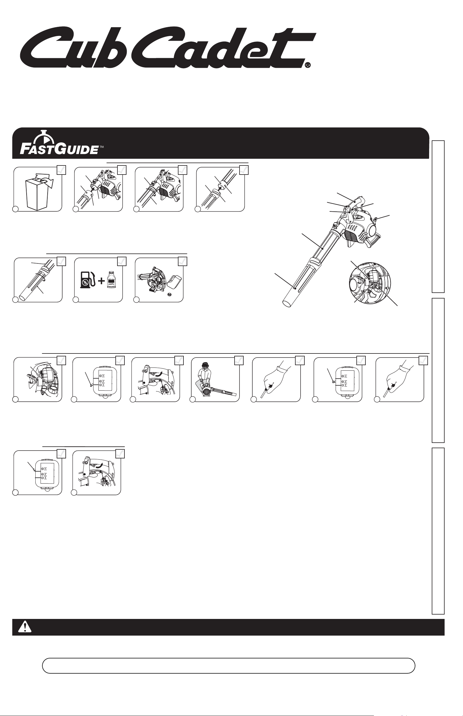
Removing Unit From Carton
11 2
Remove all contents from
carton.
Assemble The Unit
Tub e
5 6 7
Twist nozzle clockwise until
tight.
Nozzle
Assemble The Unit
Outlet
Tub e
Slot
Bump
Insert bump on blower
tube into slot on blower
outlet.
40:1
1 Gallon 3.2 oz
Mix thoroughly in separate
fuel can:
– 3.2 fl. oz. of 2-cycle
engine oil
– 1 gallon of unleaded
gasoline
NOTE: Do not mix directly in
fuel tank.
Outlet
3
Twist blower tube clockwise
until bump locks into place.
Place unit on a level surface.
Fill fuel tank.
Tub e
Tub e
Nozzle
Bump
4
Insert bump on other end of
blower tube into slot on
nozzle.
Slot
No Tools Required!
On/Off Stop Control
Cruise Control
Blower Tube
Nozzle
Handle
Choke Lever
Primer Bulb
Trigger
Starter Rope
Fuel Cap
Starting The Unit
Primer
Bulb
10 X
18 9
Press primer bulb 10 times,
or until fuel is visible
Starting The Unit
Choke
Lever
115 16
Continue to squeeze
throttle. Move choke lever
to Position 3.
Choke
Lever
Move choke lever to
Position 1.
Continue to squeeze
throttle. Run unit for an
additional 60 seconds to
complete warm-up. Unit
may be used during this
time.
10
SQUEEZE and HOLD
throttle for ALL further
steps.
Call 1-877-282-8684
DIDN’T START?
Repeat these instructions.
IF engine fails to start after 2 attempts,
move choke lever to position 3 and pull
the starter rope until engine starts
IF unit still fails to start, refer to the
operator’s manual for additional starting
and troubleshooting information
5 X
11
Crouch in starting position. Pull rope 5 times. Move choke lever to
12
13
Position 2 and squeeze
throttle.
Need Help?
Choke
Lever
14
Pull rope 3-5 times to start
engine. Run unit for 30-60
seconds to warm up.
3-5 X
IMPORTANT: READ OPERATOR’S MANUAL THOROUGHLY AND FOLLOW THE SAFE OPERATION PRACTICES WHILE OPERATING THE UNIT.
Page 2

SAFETY WARNINGS FOR GAS UNITS
• Store fuel only in containers specifically designed and approved for the storage of such materials.
• Always stop the engine and allow it to cool before filling the fuel tank. Never remove the fuel tank
cap or add fuel when the engine is hot. Always loosen the fuel tank cap slowly to relieve any
pressure in the tank before fueling. Do not smoke.
• Always add fuel in a clean, well-ventilated outdoor area where there are no sparks or open flames.
Do not smoke.
• Never operate the unit without the fuel cap securely in place.
• Avoid creating a source of ignition for spilled fuel. Wipe up any spilled fuel from the unit
immediately before starting the unit. Move the unit at least 30 feet (9.1 m) from the fueling source
and site before starting the engine. Do not smoke.
• Never start or run the unit inside a closed room or building. Breathing exhaust fumes can kill.
Operate this unit only in a well-ventilated outdoor area.
WHILE OPERATING
• Wear safety glasses or goggles that are marked as meeting ANSI Z87.1-1989 standards. Also wear
ear/hearing protection when operating this unit.
• Never run the unit without the proper equipment attached.
• To reduce the risk of hearing loss associated with sound level(s), always wear ear/hearing
protection when operating this unit.
• Wear heavy long pants, boots, gloves, and a long sleeve shirt. Do not wear loose clothing, jewelery,
short pants, sandals or go barefoot. Secure hair above shoulder level.
• To avoid static electricity shock, do not wear rubber gloves or any other insulated gloves while
operating this unit.
• Use the unit only in daylight or good artificial light.
• Keep all surfaces free from oil and fuel.
• Avoid accidental starting. Be in the starting position whenever pulling the starter rope. The operator
and unit must be in a stable position while starting. Refer to Starting and Stopping Instructions.
• Do not set unit on any surface except a clean, hard area while engine is running. Debris such as
gravel, sand, dust, grass, etc. could be picked up by the air intake and thrown out by the discharge
opening, damaging unit, property, or causing serious injury to bystanders or operator.
• Use the right tool. Only use this tool for its intended purpose.
• Do not force the unit. It will do the job better and with less likelihood of injury at a rate for which it
was designed.
• Do not overreach or use from unstable surfaces such as ladders, trees, steep slopes, rooftops, etc.
Always keep proper footing and balance.
• Always hold the unit with a firm grip when operating.
• Keep hands, face, and feet away from all moving parts. Do not touch or try to stop the impeller
when it is rotating. Do not operate without guards in place.
• Do not put any object into openings. Do not use with any opening blocked; keep free of dirt, debris,
and anything that may reduce the air flow.
• Do not touch the engine or muffler. These parts get extremely hot from operation, even after the
unit is turned off.
• Do not operate the engine faster than the speed needed to do the job. Do not run the engine at
high speed when not in use.
• Always stop the engine when operation is delayed or when walking from one location to another.
• Stop the engine for maintenance, repair, to install or remove the blower tubes. The unit must be
stopped and the impeller no longer turning to avoid contact with the rotating blades.
• If you strike or come into contact with a foreign object, stop the engine immediately and check for
damage. Do not operate before repairing damage. Do not operate the unit with loose or damaged parts.
• Use only replacement parts recommended for this tool that are sold by a Cub Cadet outlet. Use of
any replacement parts purchased elsewhere may be hazardous, and will also void your warranty.
• Never use this unit for spreading chemicals, fertilizers or other substances which may contain toxic
materials.
• To reduce fire hazard, replace faulty muffler and spark arrestor. Keep the engine and muffler free
from grass, leaves, excessive grease or carbon build up.
• Turn the engine off and disconnect the spark plug for maintenance or repair.
• Never point the blower or blowing debris in the direction of people, animals, or in the direction of
windows. Always direct the blowing debris away from people, animals, and windows. Use extra
caution when blowing debris near solid objects such as trees, automobiles, walls, etc.
OTHER SAFETY WARNINGS
• Always disconnect the spark plug before performing maintenance or accessing movable parts.
• Never store the unit, with fuel in the tank, inside a building where fumes may reach an open flame
(pilot lights, etc.) or sparks (switches, electrical motors, etc.).
• Allow the engine to cool before storing or transporting. Be sure to secure the unit while transporting.
• Store the unit in a dry place, either locked up or up high to prevent unauthorized use or damage.
Keep out of the reach of children.
• Never douse or squirt the unit with water or any other liquid. Keep handles dry, clean, and free from
debris. Clean after each use, see Cleaning and Storage instructions.
• Keep these instructions. Refer to them often and use them to instruct other users. If you loan this
unit to others, also loan these instructions to them.
SPECIAL NOTE: Exposure to vibrations through prolonged use of gasoline powered hand tools could
cause blood vessel or nerve damage in the fingers, hands, and joints of people prone to circulation
disorders or abnormal swelling. Prolonged use in cold weather has been linked to blood vessel
damage in otherwise healthy people. If symptoms occur such as numbness, pain, loss of strength,
change in skin color or texture, or loss of feeling in the fingers, hands or joints, discontinue use of this
tool and seek medical attention. An anti-vibration system does not guarantee avoidance of these
problems. Users who operate power tools on a regular basis must closely monitor their physical
condition and the condition of this tool.
SAVE THESE INSTRUCTIONS
2
SAFETY INFORMATION
SPARK ARRESTOR NOTE
NOTE: For users on U.S. Forest Land and in the states of California, Maine, Oregon and Washington.
All U.S. Forest Land and the state of California (Public Resources Codes 4442 and 4443), Oregon and
Washington require, by law that certain internal combustion engines operated on forest brush and/or grasscovered areas be equipped with a spark arrestor, maintained in effective working order, or the engine be
constructed, equipped and maintained for the prevention of fire. Check with your state or local authorities for
regulations pertaining to these requirements. Failure to follow these requirements could subject you to liability
or a fine. This unit is factory equipped with a spark arrestor. If it requires replacement, ask your LOCAL
SERVICE DEALER to install the Accessory Part #753-06027 Muffler Assembly.
READ ALL INSTRUCTIONS BEFORE OPERATING
• Read the instructions carefully. Be familiar with the controls and proper use of the unit.
• Do not operate this unit when tired, ill, or under the influence of alcohol, drugs, or medication.
• Children and teens under the age of 15 must not use the unit, except for teens guided by an adult.
• All guards and safety attachments must be installed properly before operating the unit.
• Inspect the unit before use. Replace damaged parts. Check for fuel leaks. Make sure all fasteners
are in place and secure. Replace parts that are cracked, chipped, or damaged in any way. Do not
operate the unit with loose or damaged parts.
• Carefully inspect the area before starting the unit. Remove all debris and hard or sharp objects such
as glass, wire, etc.
• Clear the area of children, bystanders, and pets. At a minimum, keep all children, bystanders, and pets
outside a 50 feet (15 m) radius; there still may be a risk to bystanders from thrown objects. Bystanders
should be encouraged to wear eye protection. If you are approached, stop the unit immediately.
• IMPORTANT SAFETY INSTRUCTIONS •
SERVICE INFORMATION
TABLE OF CONTENTS
Service Information . . . . . . . . . . . . . . . . . . . . . . . . . . . . . . . . . . . . . . . . . . . . . . . . . . . . . . . . . . . . . . . .2
Safety Information . . . . . . . . . . . . . . . . . . . . . . . . . . . . . . . . . . . . . . . . . . . . . . . . . . . . . . . . . . . . . . . .2
Know Your Unit . . . . . . . . . . . . . . . . . . . . . . . . . . . . . . . . . . . . . . . . . . . . . . . . . . . . . . . . . . . . . . . . . . .3
Assembly Instructions . . . . . . . . . . . . . . . . . . . . . . . . . . . . . . . . . . . . . . . . . . . . . . . . . . . . . . . . . . . . .3
Oil and Fuel Information . . . . . . . . . . . . . . . . . . . . . . . . . . . . . . . . . . . . . . . . . . . . . . . . . . . . . . . . . . . .3
Starting and Stopping Instructions . . . . . . . . . . . . . . . . . . . . . . . . . . . . . . . . . . . . . . . . . . . . . . . . . . . .3
Operating Instructions . . . . . . . . . . . . . . . . . . . . . . . . . . . . . . . . . . . . . . . . . . . . . . . . . . . . . . . . . . . . .3
Maintenance and Repair Instructions . . . . . . . . . . . . . . . . . . . . . . . . . . . . . . . . . . . . . . . . . . . . . . . . . .4
Cleaning and Storage . . . . . . . . . . . . . . . . . . . . . . . . . . . . . . . . . . . . . . . . . . . . . . . . . . . . . . . . . . . . . .4
Troubleshooting . . . . . . . . . . . . . . . . . . . . . . . . . . . . . . . . . . . . . . . . . . . . . . . . . . . . . . . . . . . . . . . . . .4
Specifications . . . . . . . . . . . . . . . . . . . . . . . . . . . . . . . . . . . . . . . . . . . . . . . . . . . . . . . . . . . . . . . . . . . .4
Warranty Information . . . . . . . . . . . . . . . . . . . . . . . . . . . . . . . . . . . . . . . . . . . . . . . . . . . . . . . . . . . . .16
All information, illustrations, and specifications in this manual are based on the latest product information
available at the time of printing. We reserve the right to make changes at any time without notice.
Copyright© 2010 MTD SOUTHWEST INC, All Rights Reserved.
DO NOT RETURN THIS UNIT TO THE RETAILER. PROOF OF PURCHASE WILL BE REQUIRED
FOR WARRANTY SERVICE.
For assistance regarding the assembly, controls, operation or maintenance of the unit, please call the
Customer Support Department at 1-877-282-8684 in the United States or 1-800-668-1238 in Canada.
Additional information about the unit can be found on our website at www.cubcadet.com or
www.cubcadet.ca.
For service, please call the Customer Support Department to obtain a list of authorized service dealers
near you. Service on this unit, both within and after the warranty period, should only be performed by an
authorized and approved service dealer. When servicing, use only identical replacement parts.
Before calling for service, locate the unit’s model plate, which lists the model and serial numbers of
your unit. Refer to the sample plate below and copy the information for future reference.
Copy the serial number here:
Copy the model and parent part numbers here:
Read the Operator’s Manual and follow all warnings and safety instructions. Failure to do so
can result in serious injury to the operator and/or bystanders.
FOR QUESTIONS, CALL 1-877-282-8684 IN THE U.S. OR 1-800-668-1238 IN CANADA
CALIFORNIA PROPOSITION 65 WARNING
WARNING
THE ENGINE EXHAUST FROM THIS PRODUCT CONTAINS CHEMICALS KNOWN TO THE STATE
OF CALIFORNIA TO CAUSE CANCER, BIRTH DEFECTS OR OTHER REPRODUCTIVE HARM.
WARNING: When using the unit, you must follow the safety rules. Please read these
instructions before operating the unit in order to ensure the safety of the operator and any
bystanders. Please keep these instructions for later use.
WARNING: Gasoline is highly flammable, and its vapors can explode if ignited. Take the
following precautions:
SAFETY INFORMATION
• SAFETY ALERT SYMBOLS •
Safety alert symbols are used to draw your attention to possible dangers. These symbols, and their
explanations, deserve your careful attention and understanding. The safety warnings do not by
themselves eliminate any danger. The instructions or warnings they give are not substitutes for
proper accident prevention measures. These safety instructions are not meant to cover every
possible condition that may occur. If questions arise, please call the Customer Support
Department at 1-877-282-8684 (U.S.) or 1-800-668-1238 (Canada).
DANGER: Signals an EXTREME hazard.
Failure to obey a safety DANGER signal WILL result in serious injury or death to yourself or
to others.
WARNING: Signals a SERIOUS hazard.
Failure to obey a safety WARNING signal CAN result in serious injury to yourself or to others.
CAUTION: Signals a MODERATE hazard.
Failure to obey a safety CAUTION signal MAY result in property damage or injury to
yourself or to others.
IMPORTANT! Signals special mechanical information.
NOTE: Signals additional important general information.
SYMBOL MEANING
• SAFETY AND INTERNATIONAL SYMBOLS •
This operator's manual describes safety and international symbols and pictographs that may appear on this product.
Read the operator's manual for complete safety, assembly, operating, maintenance and repair information.
SYMBOL MEANING
• SAFETY ALERT SYMBOL
Indicates danger, warning or caution. May be used in conjunction with other symbols
or pictographs.
• READ OPERATOR'S MANUAL
WARNING: Read the operator’s manual(s) and follow all warnings and safety
instructions. Failure to do so can result in serious injury to the operator and/or bystanders.
• WEAR EYE AND HEARING PROTECTION
WARNING: Thrown objects and loud noise can cause severe eye injury and hearing
loss. Wear eye protection meeting ANSI Z87.1-1989 standards and ear protection when
operating this unit. Use a full face shield when needed.
• UNLEADED FUEL
Always use clean, fresh unleaded fuel
• OIL
Refer to operator’s manual for the proper type of oil.
• DO NOT USE E85 FUEL IN THIS UNIT
WARNING: It has been proven that fuel containing greater than 15% ethanol will
likely damage this engine and void the warranty.
MODEL :
S/N :
ITEM :
Page 3
OIL AND FUEL MIXING INSTRUCTIONS
Old and/or improperly mixed fuel are the main reasons for the unit not running properly. Be sure to use fresh, clean
unleaded fuel. Follow the instructions carefully for the proper fuel/oil mixture.
Definition of Blended Fuels
Today's fuels are often a blend of gasoline and oxygenates such as ethanol, methanol, or MTBE (ether). Alcoholblended fuel absorbs water. As little as 1% water in the fuel can make fuel and oil separate. It forms acids when
stored. When using alcohol-blended fuel, use fresh fuel (less than 30 days old).
Using Blended Fuels
If you choose to use a blended fuel, or its use is unavoidable, follow recommended precautions:
• Always use the fresh fuel mix explained in your operator's manual
• Always agitate the fuel mix before fueling the unit
• Drain the tank and run the engine dry before storing the unit
Using Fuel Additives
The bottle of 2-cycle oil that came with your unit contains a fuel additive which will help inhibit corrosion and minimize
the formation of gum deposits. It is recommended that you use our 2-cycle oil with this unit. If unavailable, use a good
2-cycle oil designed for air-cooled engines along with a fuel additive, such as STA-BIL® Gas Stabilizer or an
equivalent. Add 0.8 oz. (23 ml) of fuel additive per gallon of fuel according to the instructions on the container. NEVER
add fuel additives directly to the unit's fuel tank.
Thoroughly mix the proper ratio of 2-cycle engine oil with unleaded gasoline in a separate fuel can. Use a 40:1 fuel/oil
ratio. Do not mix them directly in the engine fuel tank. See the table below for specific gas and oil mixing ratios.
NOTE: One gallon (3.8 liters) of unleaded gasoline mixed with one 3.2 oz. (95 ml.) bottle of 2-cycle oil makes a 40:1
fuel/oil ratio.
NOTE: Dispose of the old fuel/oil mix in accordance to federal, state and local regulations.
3
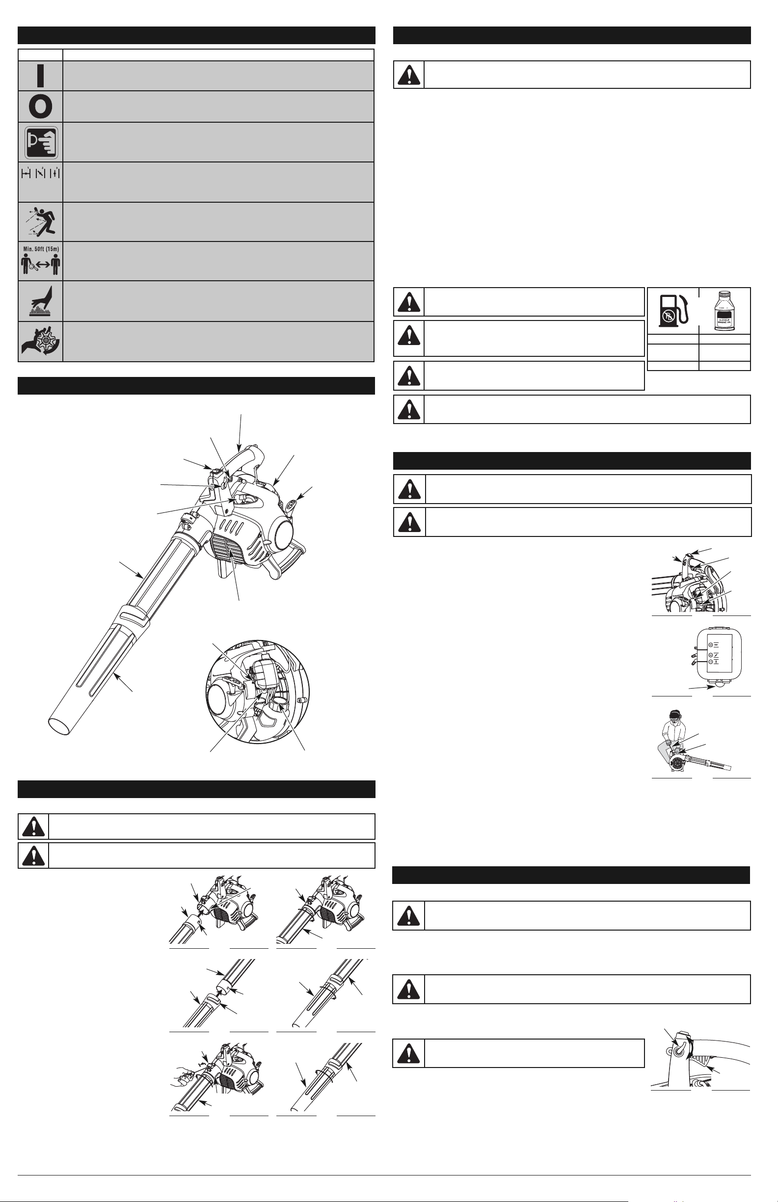
KNOW YOUR UNIT
Handle
ASSEMBLING THE UNIT
Installing the Blower Tube
1. Align the bump on the end of the blower tube
with the bump slot on the bottom end of the
blower outlet (Fig. 1).
2. Insert the bump on the blower tube into the
bump slot on the blower outlet (Fig. 1).
3. Twist the blower tube clockwise inside the
blower outlet until the bump locks into place
(Fig. 2).
Installing the Nozzle
1. Align the bump on the end of the blower tube
with the bump slot on the top end of the nozzle
(Fig. 3).
2. Insert the bump on the blower tube into the
bump slot on the nozzle (Fig. 3).
3. Twist the nozzle clockwise over the blower
tube until tight (Fig. 4).
Removing the Blower Tube
1. Hold the unit firmly.
2. Insert a flathead screwdriver into the tube lock
and twist the screwdriver counterclockwise
1/4 turn and hold it there (Fig. 5).
3. While holding the screwdriver in a
counterclockwise position, grasp the blower
tube and twist it counterclockwise (Fig. 5).
4. Pull the blower tube from the blower outlet.
Removing the Nozzle
1. Hold the blower tube firmly.
2. Grasp the nozzle and twist it counterclockwise
until the nozzle unlocks from the blower tube
(Fig. 6).
3. Remove the nozzle from the blower tube.
ASSEMBLY INSTRUCTIONS
WARNING:
To avoid serious personal injury and damage to the unit, shut the unit off before removing
or installing the blower tubes.
*WARNING: DO NOT USE E85 FUEL IN THIS UNIT.
It has been proven that fuel containing greater than 15% ethanol will likely
damage this engine and void the warranty.
WARNING:
Gasoline is extremely flammable. Ignited vapors may
explode. Always stop the engine and allow it to cool before filling the
fuel tank. Do not smoke while filling the tank. Keep sparks and open
flames at a distance from the area.
CAUTION:
For proper engine operation and maximum reliability, pay strict attention to the oil and fuel
mixing instructions on the 2-cycle oil container. Using improperly mixed fuel can severely damage the engine.
WARNING:
Remove fuel cap slowly to avoid injury from fuel spray.
Never operate the unit without the fuel cap securely in place.
OIL AND FUEL INFORMATION
SYMBOL MEANING
• ON/OFF STOP CONTROL
ON / START / RUN
• ON/OFF STOP CONTROL
OFF or STOP
• PRIMER BULB
Push primer bulb, fully and slowly, 10 times.
• CHOKE CONTROL
1. • FULL choke position
2. • PARTIAL choke position
3. • RUN choke position
• THROWN OBJECTS CAN CAUSE SEVERE INJURY
WARNING: Small objects can be propelled at high speed, causing injury.
• KEEP BYSTANDERS AWAY
WARNING:
Keep all bystanders, especially children and pets, at least 50 feet (15 m)
from the operating area.
• HOT SURFACE
WARNING:
Do not touch a hot engine. These parts get extremely hot from
operation and may cause severe burns. When the unit is turned off, the engine will
remain hot for a short time.
• BLOWERS – ROTATING IMPELLER BLADES CAN CAUSE SEVERE INJURY
WARNING:
Stop the engine and allow the impeller to stop before installing or
changing tubes, or before cleaning or performing any maintenance.
WARNING:
To prevent serious personal injury or damage to the unit, the blower tube must be installed
while operating this unit.
SAFETY INFORMATION
Blower
Outlet
Blower Tube
Fig. 2
MIXING RATIO - 40:1
UNLEADED GAS* 2-CYCLE OIL
1 GALLON US
(3.8 LITERS)
3.2 FL. OZ.
(95 ml)
1 LITER 25 ml
+
APPLICATIONS
Cleaning yards, garages, driveways, porches, patios,
around walls, fences and more
Trigger
On/Off Stop Control
Cruise Control
Spark Plug
Blower Tube
Nozzle
Muffler Cover
Air Filter Cover
Starter Rope Grip
Choke Lever
Primer Bulb
Fuel Cap
Blower Outlet
Bump
Slot
Bump
Fig. 1
Tube Lock
Blower Outlet
Blower Tube
Fig. 5
Nozzle
Blower
Tub e
Fig. 4
Nozzle
Blower
Tub e
Fig. 6
Blower
Tub e
Bump
Bump
Slot
Fig. 3
Blower
Tub e
Nozzle
WARNING:
Add fuel in a clean, well ventilated outdoor area. Wipe up any spilled fuel immediately.
Avoid creating a source of ignition for spilled fuel. Do not start the engine until fuel vapors dissipate.
STARTING INSTRUCTIONS
1. Mix gas with oil. Fill the fuel tank with fresh fuel/oil mixture. See Oil and Fuel
Mixing Instructions.
NOTE: There is no need to turn the unit on. The On/Off switch is in the ON ( I )
position at all times (Fig. 7).
2. Fully press and release the primer bulb 10 times, slowly. Some amount of fuel
should be visible in the primer bulb (Fig. 7). If fuel cannot be seen in the bulb,
press and release the bulb until fuel is visible.
3. Move the choke lever to Position 1 (Fig. 8).
4. Squeeze and hold the trigger or press down the cruise control (Fig. 7).
5. Continue to squeeze the trigger or keep the cruise control down. Place the
unit on a firm, flat surface. Crouch in the starting position and hold the unit firmly
(Fig. 9).
6. Continue to squeeze the trigger or keep the cruise control down. Pull the
starter rope out until some resistance is felt. This is usually around 2–4 inches.
Pull the starter rope 5 times in a controlled and steady motion.
7. Continue to squeeze the trigger or keep the cruise control down. Move the
choke lever to Position 2 (Fig. 8).
8. Continue to squeeze the trigger or keep the cruise control down. Pull the
starter rope 3-5 times in a controlled and steady motion to start the engine.
9. Continue to squeeze the trigger or keep the cruise control down. Allow the
engine to warm up for 30-60 seconds.
10. Continue to squeeze the trigger or keep the cruise control down. Move the
choke lever to Position 3 (Fig. 8).
11. Continue to squeeze the trigger or keep the cruise control down. Continue
warming the engine for an additional 60 seconds. The unit is now ready for use.
IF... The engine does not start, go back to step 2.
IF... The engine fails to start after 2 attempts, move the choke lever to Position
3, squeeze the trigger, and pull the starter rope 3-8 times in a controlled
and steady motion. The engine should start. If not, repeat.
IF WARM... If the engine is already warm, move the choke lever to Position 2, squeeze the trigger and pull the starter
rope to restart.
STOPPING INSTRUCTIONS
1. Release the trigger or raise the cruise control to idle the engine.
2. Press and hold the On/Off switch in the OFF (O) position until the engine comes to a complete stop (Fig. 7).
STARTING AND STOPPING INSTRUCTIONS
WARNING: Avoid accidental starting. Make sure you are in the starting position when pulling the starter
rope (Fig. 9). To avoid serious injury, the operator and unit must be in a stable position while starting.
To avoid serious personal injury, make sure that the blower tube is locked in place.
Cruise
Control
On/Off Switch
Primer
Bulb
Fig. 7
Starter Rope
Fig. 9
WARNING:
Operate this unit only in a well-ventilated outdoor area. Carbon monoxide exhaust fumes
can be lethal in a confined area.
Fig. 8
Primer Bulb
Position 3
Choke
Lever
Trigger
Trigger
Starting Position
Position 2
Position 1
OPERATING INSTRUCTIONS
HOLDING THE BLOWER
Before operating the unit, stand in the operating position. Check for the following:
• Operator is wearing proper clothing, such as boots, safety glasses or goggles, ear/hearing protection, gloves, long
pants and long sleeve shirt
• If the conditions are dusty, the operator is wearing a dust mask or face mask
• The unit is in good working condition
• The tubes are in place and secure
OPERATING TIPS
Using the Cruise Control
1. Once the engine has started and warmed up, squeeze the trigger to accelerate
the unit as needed (Fig. 10).
2. For longer periods of operation and to eliminate possible finger fatigue, move the cruise control toward the FAST
position to incrementally increase or maintain the unit’s engine speed (Fig. 10). When the cruise control is pressed,
the trigger will recede into the handle.
3. To decrease engine speed, move the cruise control to the SLOW position and the trigger will return to idle (Fig. 10).
Fig. 10
WARNING: After starting the unit, always stand on the left side of the unit to operate it as shown in
figure 11 to keep from blocking the air intake.
WARNING: To avoid serious personal injury, wear goggles or safety glasses at all times when
operating this unit. Wear a face mask or dust mask in dusty locations.
WARNING:
To prevent serious personal injury or damage to the
unit, make sure blower tubes are in place before you operate the unit.
SLOW
FAST
Cruise
Control
Trigger
(Idle Position)
Page 4
CLEANING
Use a small brush to clean off the outside of the unit. Do not use strong detergents. Household cleaners that contain
aromatic oils such as pine and lemon, and solvents such as kerosene, can damage the plastic housing or handle. Wipe
off any moisture with a soft cloth.
STORAGE
• Never store a fueled unit where fumes may reach an open flame or spark.
• Allow the engine to cool before storing.
• Store the unit locked up to prevent unauthorized use or damage.
• Store the unit in a dry, well-ventilated area.
• Store the unit out of the reach of children.
LONG TERM STORAGE
If planning on storing the unit for an extended time, use the following storage procedure:
1. Drain all fuel from the fuel tank into a container with the same 2-cycle fuel mixture. Do not use fuel that has been
stored for more than 30 days. Dispose of the old fuel/oil mix in accordance with federal, state and local regulations.
2. Start the engine and allow it to run until it stalls. This ensures that all fuel has been drained from the carburetor.
3. Allow the engine to cool. Remove the spark plug and put 5 drops of any high quality motor oil or 2-cycle oil into the
cylinder. Pull the starter rope slowly to distribute the oil. Reinstall the spark plug.
NOTE: Remove the spark plug and drain all of the oil from the cylinder before attempting to start the unit after storage.
4. Thoroughly clean the unit and inspect it for any loose or damaged parts. Repair or replace damaged parts and
tighten loose screws, nuts or bolts. The unit is ready for storage.
TRANSPORTING
• Allow the engine to cool before transporting
• Drain the fuel from the unit
• Tighten the fuel cap before transporting
• Secure the unit while transporting
CAUSE SOLUTION
The fuel is old and/or improperly mixed Drain the fuel tank and add fresh, properly mixed fuel
The air filter is plugged Clean or replace the air filter
The spark plug is fouled Clean, gap or replace the spark plug
CAUSE SOLUTION
The fuel is old and/or improperly mixed Drain the fuel tank and add fresh, properly mixed fuel
The air filter is plugged Clean or replace the air filter
CAUSE SOLUTION
The fuel tank is empty Fill the fuel tank with properly mixed fuel
The primer bulb was not pressed enough Press the primer bulb fully and slowly 10 times
The engine is flooded
Move the choke lever to Position 3, hold down the
trigger and pull the starter rope
The fuel is old and/or improperly mixed Drain the fuel tank and add fresh, properly mixed fuel
The spark plug is fouled Clean, gap or replace the spark plug
CAUSE SOLUTION
The air filter is plugged Clean or replace the air filter
The fuel is old and/or improperly mixed Drain the fuel tank and add fresh, properly mixed fuel
TROUBLESHOOTING
THE ENGINE WILL NOT START
THE ENGINE WILL NOT IDLE
THE ENGINE WILL NOT ACCELERATE
NOTE: For repairs beyond the minor adjustments listed above, locate your nearest authorized service center by
calling the Customer Support Department at 1-877-282-8684 (U.S.) or 1-800-668-1238 (Canada).
THE ENGINE LACKS POWER OR STALLS
ENGINE*
Engine Type. . . . . . . . . . . . . . . . . . . . . . . . . . . . . . . . . . . . . . . . . . . . . . . . . . . . . . . . . . . . . . . . . . . . . Air-Cooled, 2-Cycle
Displacement . . . . . . . . . . . . . . . . . . . . . . . . . . . . . . . . . . . . . . . . . . . . . . . . . . . . . . . . . . . . . . . . . . . . . . . . . . . . . . . 27 cc
Idle Speed RPM . . . . . . . . . . . . . . . . . . . . . . . . . . . . . . . . . . . . . . . . . . . . . . . . . . . . . . . . . . . . . . . . . . . 3,600–4,200 rpm
Operating RPM . . . . . . . . . . . . . . . . . . . . . . . . . . . . . . . . . . . . . . . . . . . . . . . . . . . . . . . . . . . . . . . . . . . . 6,800–8,500 rpm
Blower Velocity . . . . . . . . . . . . . . . . . . . . . . . . . . . . . . . . . . . . . . . . . . . . . . . . . . . . . . . . . . . . . . . . . . 150 mph (241 kmh)
Blower Air Output . . . . . . . . . . . . . . . . . . . . . . . . . . . . . . . . . . . . . . . . . . . . . . . . . . . . . . . . . . . . . . . 500 cfm (14.15 cmm)
Ignition Type . . . . . . . . . . . . . . . . . . . . . . . . . . . . . . . . . . . . . . . . . . . . . . . . . . . . . . . . . . . . . . . . . . . . . . . . . . . . Electronic
Ignition Switch . . . . . . . . . . . . . . . . . . . . . . . . . . . . . . . . . . . . . . . . . . . . . . . . . . . . . . . . . . . . . Momentary On/Off Switch
Spark Plug Gap . . . . . . . . . . . . . . . . . . . . . . . . . . . . . . . . . . . . . . . . . . . . . . . . . . . . . . . . . . . . . . . . . 0.025 in. (0.635 mm)
Lubrication. . . . . . . . . . . . . . . . . . . . . . . . . . . . . . . . . . . . . . . . . . . . . . . . . . . . . . . . . . . . . . . . . . . . . . . . . Fuel/Oil Mixture
Fuel/Oil Ratio . . . . . . . . . . . . . . . . . . . . . . . . . . . . . . . . . . . . . . . . . . . . . . . . . . . . . . . . . . . . . . . . . . . . . . . . . . . . . . . . 40:1
Carburetor. . . . . . . . . . . . . . . . . . . . . . . . . . . . . . . . . . . . . . . . . . . . . . . . . . . . . . . . . . . . . . . . . . . Diaphragm, All-Position
Starter. . . . . . . . . . . . . . . . . . . . . . . . . . . . . . . . . . . . . . . . . . . . . . . . . . . . . . . . . . . . . . . . . . . . . . . . . . . AST Auto Rewind
Muffler. . . . . . . . . . . . . . . . . . . . . . . . . . . . . . . . . . . . . . . . . . . . . . . . . . . . . . . . . . . . . . . . . . . . . . . . . . Baffled with Guard
Throttle . . . . . . . . . . . . . . . . . . . . . . . . . . . . . . . . . . . . . . . . . . . . . . . . . . . . . . . . . . . . . . . . . . . . . . . . . . . . Variable Speed
Fuel Tank Capacity . . . . . . . . . . . . . . . . . . . . . . . . . . . . . . . . . . . . . . . . . . . . . . . . . . . . . . . . . . . . . . . . . . . 14 oz. (414 ml)
Approximate Weight (no fuel) . . . . . . . . . . . . . . . . . . . . . . . . . . . . . . . . . . . . . . . . . . . . . . . . . . . . . . . . . . 12 lbs. (5.44 kg)
SPECIFICATIONS
* All specifications are based on the latest product information available at the time of printing. We reserve the right
to make changes at any time without notice.
WARNING:
To avoid serious personal injury, always turn your unit off and allow it to cool before you
clean or do any maintenance on it.
CLEANING AND STORAGE
REPLACING THE SPARK PLUG
Use a replacement part number 753-05784. The correct spark gap is 0.025 in. (0.635 mm).
Remove the plug after every 25 hours of operation and check its condition.
1. Stop the engine and allow it to cool.
2. Grasp the plug boot firmly and pull the cap from the spark plug.
3. Clean dirt from around the spark plug. Remove the spark plug from the cylinder
head by turning a 5/8 in. socket counterclockwise.
4. Replace cracked, fouled or dirty spark plug. Set the spark gap at 0.025 in. (0.635 mm) using a feeler gauge (Fig. 19).
5. Install a correctly-gapped spark plug in the cylinder head. Turn the 5/8 in. socket clockwise until snug.
If using a torque wrench, torque to:
110-120 in.•lb. (12.3-13.5 N•m)
Do not over tighten.
6. Reinstall the spark plug boot.
4
MAINTENANCE AND REPAIR INSTRUCTIONS
MAINTENANCE AND REPAIR INSTRUCTIONS
MAINTENANCE SCHEDULE
Perform these required maintenance procedures at the frequency stated in the table. These procedures should also be
a part of any seasonal tune-up.
NOTE: Some maintenance procedures may require special tools or skills. If you are unsure about these procedures,
take the unit to a Cub Cadet or other qualified service dealer.
NOTE: Maintenance, replacement, or repair of the emission control devices and system may be performed by a
Cub Cadet or other qualified service dealer.
WARNING:
To prevent serious injury, never perform maintenance or repairs with unit running. Always
service and repair a cool unit. Disconnect the spark plug wire to ensure that the unit cannot start.
FREQUENCY MAINTENANCE REQUIRED SEE
Before starting the engine Fill the fuel tank with fresh fuel mixture* p. 3
Every 10 hours Clean and re-oil the air filter p. 4
Every 25 hours Check the spark plug condition and gap p. 4
* DO NOT use E85 fuel in this unit. It has been proven that fuel containing greater than 15% ethanol will likely
damage this engine and void the warranty.
OPERATING INSTRUCTIONS
Other Tips
• Assure the unit is not directed at anybody or any loose debris before starting the unit.
• Verify that the unit is in good working condition. Make sure the tubes are in place and secure.
• Always hold the unit securely when operating. Keep a firm grip on the handle.
• To reduce the risk of hearing loss associated with sound level(s), hearing protection is required.
• Operate power equipment only at reasonable hours— not early in the morning or late at night when people might
be disturbed. Comply with times listed in local ordinances. Usual recommendations are 9:00 am to 5:00 pm,
Monday through Saturday.
• To reduce noise levels, limit the number of pieces of equipment used at any one time.
• To reduce noise levels, operate power blowers at the lowest possible speed to do the job.
• Check your equipment before operation, especially the muffler, air intakes and air filters.
• Use rakes and brooms to loosen debris before blowing.
• In dusty conditions, slightly dampen surfaces or use a mister attachment when water is available.
• Conserve water by using power blowers instead of hoses for many lawn and garden applications, including areas
such as screens, patios, grills, porches, and gardens.
• Watch out for children, pets, open windows or freshly washed cars, and blow
debris safely away.
• Clean up after using blowers and other equipment. Dispose of debris appropriately.
• Use the blower for trees, shrubs, flower beds and hard-to-clean areas. Also use
the unit around buildings, walls, overhangs, fences and screens, and for other
normal cleaning procedures.
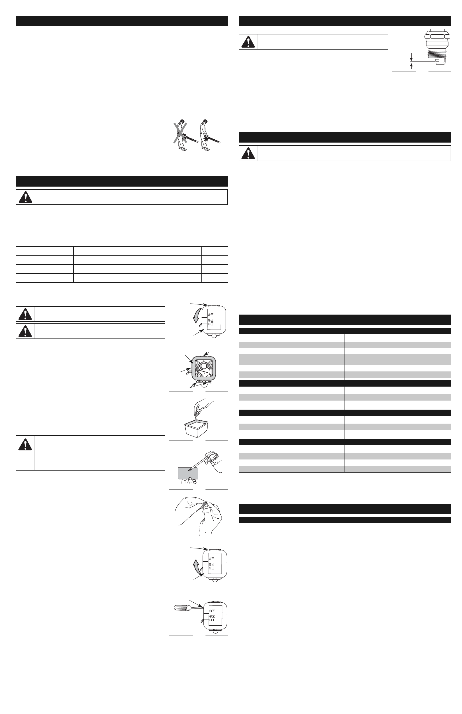
• Hold the blower with the right hand. Do not stand on the right side of the blower
when operating the unit (Fig. 11). If you do, you will be blocking the air intake and
this will affect the unit’s performance. Instead, be sure to stand on the left side of
the unit to maximize the unit’s efficiency (Fig. 11).
Fig. 11
INCORRECT
POSITION
CORRECT
POSITION
AIR FILTER MAINTENANCE
Cleaning the Air Filter
Clean and re-oil the air filter every 10 hours of operation. It is an important item to
maintain. Failure to maintain your air filter properly can result in poor performance or
can cause permanent damage to your engine.
1. Open the air filter cover. Push the locking tab on the top of the cover inward, then
pull the air filter cover out and down. (Fig. 12).
2. Remove the air filter (Fig. 13).
3. Wash the filter in detergent and water (Fig. 14). Rinse the filter thoroughly and
allow it to dry.
4. Apply enough clean SAE 30 motor oil to lightly coat the filter (Fig. 15).
5. Squeeze the filter to spread and remove excess oil (Fig. 16).
6. Replace the filter (Fig. 13).
NOTE: If the unit is operated without the air filter, you will VOID the warranty.
7. Reinstall the air filter cover. Position the slots on the bottom of the air filter cover
onto the tabs at the bottom of the back plate (Fig. 13).
8. Swing the cover up until the tab on the air filter backplate snaps into place in the
slot on the air filter cover (Fig. 17).
CARBURETOR ADJUSTMENT
The idle speed of the engine is adjustable. An idle adjustment screw is between the
air filter cover and the engine starter housing (Fig. 18).
NOTE: Careless adjustments can seriously damage your unit. An authorized
service dealer should make carburetor adjustments.
Check Fuel Mixture
Old fuel is usually the reason for improper unit performance. Drain and refill the tank with
fresh fuel mixture prior to making any adjustments. Refer to Oil and Fuel Information.
Clean Air Filter
The condition of the air filter is important to the operation of the unit. A dirty air filter
will restrict air flow. This is often mistaken for an out of adjustment carburetor. Check
the condition of the air filter before adjusting the idle speed screw. Refer to Air Filter
Maintenance.
Adjust Idle Speed Screw
If, after checking the fuel and cleaning the air filter, the engine still will not idle, adjust
the idle speed screw as follows:
1. Start the engine and let it run at a high idle for a minute to warm up. Refer to
Starting/Stopping Instructions.
2. Release the throttle trigger and let the engine idle. If the engine stops, insert a
small Phillips in between the air filter cover and the engine cover (Fig. 18). Turn the
idle speed screw in, clockwise, 1/8 of a turn at a time (as needed) until the engine
idles smoothly.
Checking the fuel, cleaning the air filter, and adjusting the idle speed should solve
most engine problems. If not and all of the following are true:
• the engine will not idle
• the engine hesitates or stalls on acceleration
• there is a loss of engine power
Have the carburetor adjusted by an authorized service dealer.
WARNING: To avoid serious personal injury, always turn your
trimmer off and allow it to cool before you clean or service it.
WARNING: Wear gloves to prevent injury when handling unit.
WARNING:
This unit will need to be running during idle speed
adjustment. Wear protective clothing and observe all safety
instructions to prevent serious personal injury.
Also, DO NOT set unit on any surface except a clean, hard area while
starting or performing any adjustments. Debris, such as gravel, sand,
dust, grass, etc., could be thrown by the blower tube and damage
property or cause serious injury to bystanders or operator.
CAUTION:
Do not sand blast, scrape, or clean electrodes. Grit in
the engine could damage the cylinder.
Fig. 12
Locking Tab
Air Filter Cover
Fig. 13
Locking Tab
Tab s
Fig. 14
Fig. 15
Fig. 17
Locking Tab
Air Filter Cover
Fig. 18
Idle Adjustment
Screw
Air Filter
Back
Plate
Fig. 19
0.025 in.
(0.635 mm)
Fig. 16
Page 5

BESOIN D’AIDE ? POUR VOS QUESTIONS, APPELEZ LE 1-877-282-8684
AUX É.-U. OU LE 1-800-668-1238 AU CANADA
PART NO. 769-05636 P00 (07/10)
HB227
Souffleur thermique
2 temps
Español — Page 9 English — Page 1Français — Page 5
Manuel de l’utilisateur
Retirer l’appareil du carton
11 2
Retirez tous les éléments du
carton.
Assembler l’appareil
Tub e
5
Pivotez la buse vers la droite
jusqu’à ce qu'elle soit bien
serrée.
Démarrer l’appareil
Poire
d’amorçage
Buse
Assembler l’appareil
Sortie
Tub e
Encoche
Partie saillante
Insérez la partie saillante
du tube de soufflage dans
l’encoche sur la sortie du
souffleur.
40:1
1 Gallon 3,2 oz
6 7
Mélangez soigneusement
dans un bidon d’essence :
– 0,95 dl (3,2 oz) d’huile
pour moteur 2 temps
– 3,8 l (1 gal) d’essence
sans plomb
REMARQUE : ne faites pas
le mélange directement
dans le réservoir de
carburant.
Levier
d’étranglement
Sortie
3
Pivotez le tube de soufflage
vers la droite jusqu’à ce que
la partie saillante soit
parfaitement en place.
Placez l’appareil sur une
surface plane. Remplissez le
réservoir de carburant.
Tub e
Tub e
Buse
Partie
saillante
4
Insérez la partie saillante à
l’autre extrémité du tube de
soufflage dans l’encoche
située sur la buse.
Encoche
Aucun outil nécessaire !
Poignée
Commande marche/arrêt
Régulateur de vitesse
Tube de soufflage
Buse
Poire d’amorçage
Levier
d’étranglement
Levier
d’étranglement
Gâchette
Cordon de
démarrage
Bouchon de réservoir
de carburant
10 X
18 9
Pressez la poire
d’amorçage 10 fois ou
jusqu’à ce que le carburant
soit visible.
Démarrer l’appareil
Levier
d’étranglement
115 16
Continuez de presser la
manette des gaz. Mettez le
levier d’étranglement en
position 3.
Mettez le levier
d’étranglement en position 1.
Continuez de presser la
manette des gaz. Laissez
tourner le moteur encore
60 secondes pour terminer
le réchauffage. L’appareil
peut être utilisé pendant ce
temps.
10
MAINTENEZ la manette des
gaz ENFONCÉE TOUT AU
LONG des étapes suivantes.
11
Placez-vous en position de
démarrage.
Besoin d’aide ?
Appelez le 1-877-282-8684
L’APPAREIL NE DÉMARRE PAS ?
SI le moteur ne démarre pas après 2 tentatives, placez
le levier d’étranglement en position 3 et tirez le cordon
de démarrage jusqu’à ce que le moteur démarre
SI le moteur ne démarre toujours pas, consultez le
manuel de l’utilisateur pour plus d’informations sur le
Répétez ces étapes.
démarrage et le dépannage
5 X
12
Tirez 5 fois sur le cordon. Mettez le levier
13
d’étranglement en position
2 et pressez la manette des
gaz.
14
Tirez sur le cordon 3 à 5
fois de suite pour démarrer
le moteur. Laissez tourner
le moteur 30 à 60 secondes
pour le réchauffer.
3-5 X
IMPORTANT : LISEZ ATTENTIVEMENT LE MANUEL DE L’UTILISATEUR ET CONFORMEZ-VOUS AUX INSTRUCTIONS POUR UNE UTILISATION DE
L’APPAREIL EN TOUTE SÉCURITÉ.
Page 6

6
• Éloignez les enfants, les personnes à proximité et les animaux domestiques de la zone d’utilisation. Au
minimum, faites reculer les enfants, les personnes à proximité et les animaux domestiques de 15 m (50
pieds) ; il existe néanmoins un risque de projectile pour les personnes à proximité. Encouragez-les à
porter des lunettes de sécurité. Si quelqu’un s’approche de vous, arrêtez l’appareil immédiatement.
AVERTISSEMENTS DE SÉCURITÉ POUR LES APPAREILS A ESSENCE
• Stockez uniquement le carburant dans des conteneurs prévus spécifiquement à cet effet et
approuvés pour le stockage de telles substances.
• Coupez toujours le moteur et laissez-le refroidir avant de remplir le réservoir d’essence. Ne retirez jamais le
bouchon du réservoir d’essence et ne remplissez jamais ce dernier lorsque le moteur est chaud. Dévissez
lentement le bouchon du réservoir d’essence afin de réduire la pression avant de le remplir. Ne fumez pas.
• Ajoutez le carburant dans un endroit propre, bien aéré et dépourvu de toute source d’étincelles ou
de flammes. Ne fumez pas.
• Ne démarrez jamais l’appareil sans avoir bien revissé le bouchon du réservoir d’essence.
• Évitez tout ce qui pourrait enflammer le carburant renversé. L’essence s’étant échappée de l’appareil
doit être essuyée immédiatement avant de démarrer l'appareil. Éloignez l’appareil d’au moins 9,1 m
(30 pieds) du site et de la source du carburant avant de démarrer le moteur. Ne fumez pas.
• L'appareil ne doit pas être démarré ou utilisé à l'intérieur d'un espace ou d’un bâtiment clos. Inhaler
les fumées du pot d’échappement peut provoquer la mort. Cet appareil doit fonctionner
uniquement en extérieur, dans une zone bien aérée.
LORS D’UNE UTILISATION
• Portez des lunettes de sécurité conformes aux normes ANSI Z87.1-1989. Portez une protection
auditive lorsque vous utilisez cet appareil.
• N’utilisez jamais l’appareil sans l'accessoire adéquat.
• Pour diminuer le risque de perte d'audition due au niveau sonore, portez toujours une protection
auditive lorsque vous utilisez cet appareil.
• Portez un pantalon long et épais, des bottes, des gants et une chemise à manches longues. Ne
marchez pas pieds nus et évitez de porter des vêtements amples, des bijoux, des pantalons courts
et des sandales. Relevez les cheveux au-dessus des épaules.
• Pour éviter les chocs d'électricité statique, ne portez pas de gants en caoutchouc ou de gants
isolés en utilisant cet appareil.
• Utilisez l’appareil uniquement à la lumière du jour ou sous un éclairage artificiel satisfaisant.
• Veillez à ce que toutes les surfaces soient dépourvues d'huile et d’essence.
• Évitez les démarrages accidentels. Soyez en position de démarrage lorsque vous tirez sur le
cordon de démarrage. L’utilisateur et l’appareil doivent se trouver dans une position stable lors du
démarrage. Consultez les Instructions de démarrage et d’arrêt.
• Ne posez l’appareil que sur une surface propre et stable lorsque le moteur tourne. Les débris tels
que le gravier, le sable, la poussière, l’herbe, etc. pourraient être entraînés par une prise d’air et
éjectés par l’ouverture d’expulsion, et endommager l’appareil, les objets environnants, ou causer
des blessures graves aux personnes avoisinantes ou à l’utilisateur.
• Utilisez le bon outil. N’employez cet outil que pour son usage prévu.
• Ne forcez pas l’appareil. Il sera plus efficace et vous courrez moins de risques de blessures en
l’utilisant de façon adéquate.
• N’essayez pas d’atteindre un point trop éloigné et évitez de vous tenir sur des surfaces trop instables comme
une échelle, un arbre, une pente raide, un toit, etc. Tenez-vous toujours bien campé, en position d'équilibre.
• Gardez toujours une prise ferme sur l’appareil lorsque vous l’utilisez.
• Gardez les mains, le visage et les pieds éloignés des parties en mouvement. N’essayez pas de toucher
ou d’arrêter l’hélice lorsqu’elle tourne. N’utilisez pas l’appareil si les protections ne sont pas en place.
• N’insérez pas d’objets dans les ouvertures. N’utilisez pas l’appareil si une ouverture est obstruée ;
enlevez la poussière et les débris et tout ce qui pourrait réduire le passage de l’air.
• Ne touchez pas au moteur ni au pot d'échappement. Ces pièces deviennent extrêmement chaudes
lors du fonctionnement, même après l'arrêt de l'appareil.
• Ne faites pas tourner le moteur à une vitesse supérieure à celle qui est nécessaire pour effectuer le
travail. Ne faites pas tourner le moteur à haut régime lorsque vous n’utilisez pas l’appareil.
• Arrêtez toujours le moteur lorsque l’utilisation est interrompue ou lorsque vous vous déplacez d’un
endroit à l’autre.
• Arrêtez le moteur pour effectuer l’entretien, la réparation, pour installer ou enlever les tubes de soufflage.
L’appareil doit être arrêté et l’hélice ne doit plus tourner pour éviter tout contact avec les lames en rotation.
• Si l’appareil heurte ou se prend dans un objet, arrêtez le moteur immédiatement et vérifiez que l’appareil
n’a pas été endommagé. N’utilisez pas l’appareil avant d’avoir réparé les dommages. N’utilisez pas
l’appareil avec des pièces endommagées ou ayant du jeu.
• Utilisez uniquement des pièces de rechange recommandées pour cet outil et distribuées par un
point de vente Cub Cadet. L’utilisation de pièces de rechange non agréées peut être dangereuse et
entraînera l’annulation de votre garantie.
• N’utilisez jamais cet appareil pour répandre des produits chimiques, des engrais ou d’autres
substances pouvant contenir des matériaux toxiques.
• Afin de réduire les risques d’incendie, remplacez le pare-étincelle et les pots d’échappement
défectueux. Nettoyez l’herbe, les feuilles, les couches de graisse excessives et les dépôts de
carbone du moteur et du pot d’échappement.
• Éteignez le moteur et débranchez la bougie pour effectuer son entretien ou sa réparation.
• Ne jamais orienter le souffleur en direction de personnes ou d’animaux domestiques, ni en direction
de fenêtres. Ne jamais diriger les débris soufflés en direction de personnes, d’animaux et de
fenêtres. Faire particulièrement attention en soufflant les débris à proximité d’objets solides tels que
des arbres, voitures, murs, etc.
AUTRES AVERTISSEMENTS DE SÉCURITÉ
• Débranchez systématiquement la bougie avant d’effectuer l'entretien ou d’accéder aux pièces en
mouvement.
• N’entreposez jamais l’appareil avec de l’essence dans le réservoir à l’intérieur d’un bâtiment où les
vapeurs peuvent entrer en contact avec toute source de flammes (lampes témoin, etc.) ou
d’étincelles (interrupteurs, moteurs électriques, etc.).
• Laissez refroidir le moteur avant de le ranger ou de le déplacer. Attachez bien l’appareil pendant le transport.
• Entreposez l’appareil dans un endroit sec éventuellement sous clef ou en hauteur pour éviter tout usage
non autorisé et pour éviter qu’il soit endommagé. Gardez toujours l’appareil hors de la portée des enfants.
• Ne trempez ou n’humidifiez jamais l’appareil avec de l’eau ou tout autre liquide. Conservez les
poignées sèches et propres. Nettoyez l’appareil après chaque utilisation ; consultez les Instructions
de nettoyage et rangement.
• Conservez ces instructions. Consultez-les régulièrement et utilisez-les pour donner des consignes aux
autres utilisateurs. Si vous prêtez cet appareil à quelqu’un, transmettez également ces instructions.
REMARQUE IMPORTANTE : L'exposition aux vibrations due à une utilisation prolongée d'outils
manuels à essence peut provoquer des lésions nerveuses ou aux vaisseaux sanguins au niveau des
doigts, des mains et des articulations pour les personnes prédisposées aux problèmes de circulation
ou de gonflement anormal. Des cas de lésions aux vaisseaux sanguins ont été signalés chez des
personnes par ailleurs en bonne santé suite à une utilisation prolongée par temps froid. Si vous
constatez l’apparition de symptômes tels que des engourdissements, des douleurs, une perte de
force, un changement de couleur ou de texture de la peau, ou une perte de sensation dans les doigts,
les mains ou les articulations, cessez l'utilisation de cet outil et consultez un médecin. Un système
anti-vibration ne garantit pas d'éviter ces problèmes. Les personnes qui ont une utilisation régulière
de ces outils à moteur doivent surveiller attentivement leur condition physique et l'état de l’outil.
CONSERVEZ CES INSTRUCTIONS
INFORMATIONS SUR LA SÉCURITÉ
REMARQUE CONCERNANT LE PARE-ÉTINCELLE
REMARQUE : À l'intention des utilisateurs utilisant l’appareil dans les terres forestières des États-
Unis et dans les états de Californie, du Maine, de l'Oregon et de Washington. Toutes les terres
forestières des États-Unis et de l'état de Californie (Codes sur les ressources publiques 4442 et 4443),
de l'Oregon et de Washington exigent de par la loi que certains moteurs à combustion interne utilisés
dans des zones couvertes de taillis et/ou d'herbes soient équipés d'un pare-étincelle en parfait état de
fonctionnement, ou qu'ils soient conçus, équipés et entretenus pour la prévention des incendies.
Renseignez-vous auprès des autorités locales ou régionales concernant la réglementation en vigueur.
Vous pourriez être passible d'une amende ou être tenu responsable si vous ne respectez pas cette
réglementation. Cet appareil est équipé d'un pare-étincelle en usine. Si l'écran du pare-étincelle, réf.
753-06027, doit être remplacé, contactez votre RÉPARATEUR LOCAL AGRÉE.
LISEZ CETTE NOTICE INTÉGRALEMENT AVANT D’UTILISER CET APPAREIL :
• Lisez soigneusement les instructions. Familiarisez-vous avec les commandes et la marche à suivre
pour une bonne utilisation de l'appareil.
• N’utilisez pas cet appareil lorsque vous êtes fatigué, malade, ou sous l’influence de l’alcool, de
drogues, ou de médicaments.
• L'appareil ne doit pas être utilisé par un enfant ou adolescent de moins de 15 ans, à moins que
l'adolescent soit sous la supervision d’un adulte.
• Toutes les protections et tous les dispositifs de sécurité doivent être installés correctement avant
l’utilisation de l’appareil.
• Inspectez l’appareil avant utilisation. Remplacez les pièces endommagées. Assurez-vous qu'il n'y a
pas de fuites de carburant. Assurez-vous que toutes les attaches sont en place et solidement
fixées. Remplacez les pièces fissurées, ébréchées ou endommagées. N’utilisez pas l’appareil avec
des pièces endommagées ou ayant du jeu.
• Inspectez attentivement la zone d’utilisation avant de démarrer cet outil. Retirez tous les débris et
objets durs ou tranchants tels que du verre, des câbles, etc.
• CONSIGNES DE SÉCURITÉ IMPORTANTES •
INFORMATIONS SUR L’ENTRETIEN ET LE SERVICE APRÈS-VENTE
TABLE DES MATIÈRES
Informations sur l’entretien et le service après-vente . . . . . . . . . . . . . . . . . . . . . . . . . . . . . . . . . . . . .6
Informations sur la sécurité . . . . . . . . . . . . . . . . . . . . . . . . . . . . . . . . . . . . . . . . . . . . . . . . . . . . . . . . .6
Familiarisez-vous avec votre outil . . . . . . . . . . . . . . . . . . . . . . . . . . . . . . . . . . . . . . . . . . . . . . . . . . . .7
Instructions de montage . . . . . . . . . . . . . . . . . . . . . . . . . . . . . . . . . . . . . . . . . . . . . . . . . . . . . . . . . . . .7
Informations sur l’huile et le carburant . . . . . . . . . . . . . . . . . . . . . . . . . . . . . . . . . . . . . . . . . . . . . . . . .7
Instructions de démarrage et d’arrêt . . . . . . . . . . . . . . . . . . . . . . . . . . . . . . . . . . . . . . . . . . . . . . . . . .7
Instructions d’utilisation . . . . . . . . . . . . . . . . . . . . . . . . . . . . . . . . . . . . . . . . . . . . . . . . . . . . . . . . . . . .7
Entretien et réparations . . . . . . . . . . . . . . . . . . . . . . . . . . . . . . . . . . . . . . . . . . . . . . . . . . . . . . . . . . . .8
Nettoyage et rangement . . . . . . . . . . . . . . . . . . . . . . . . . . . . . . . . . . . . . . . . . . . . . . . . . . . . . . . . . . . .8
Résolution des problèmes . . . . . . . . . . . . . . . . . . . . . . . . . . . . . . . . . . . . . . . . . . . . . . . . . . . . . . . . . .8
Spécifications . . . . . . . . . . . . . . . . . . . . . . . . . . . . . . . . . . . . . . . . . . . . . . . . . . . . . . . . . . . . . . . . . . . .8
Garantie . . . . . . . . . . . . . . . . . . . . . . . . . . . . . . . . . . . . . . . . . . . . . . . . . . . . . . . . . . . . . . . . . . . . . . .16
Toutes les informations, illustrations et caractéristiques sont basées sur les toutes dernières informations
disponibles sur le produit, à l’impression de ce guide. Nous nous réservons le droit d’effectuer des
modifications à tout moment sans notification préalable.
Copyright© 2010 MTD SOUTHWEST INC. Tous droits réservés.
NE RAMENEZ PAS CET APPAREIL CHEZ LE DÉTAILLANT. UNE PREUVE D’ACHAT SERA
EXIGÉE POUR TOUTE PRISE EN CHARGE DANS LE CADRE DE LA GARANTIE.
Si vous éprouvez des difficultés à assembler ce produit ou si vous avez des questions sur les
commandes, l'utilisation ou l'entretien de cet appareil, veuillez contacter le service à la clientèle en
composant le 1-877-282-8684 aux États-Unis ou le 1-800-668-1238 au Canada. Des informations
supplémentaires sont disponibles sur notre site web : www.cubcadet.com ou www.cubcadet.ca.
Pour un entretien ou une réparation, veuillez appeler le service clientèle pour obtenir une liste
complète des professionnels agréés près de chez vous. L’entretien de cet appareil doit être confié
exclusivement à un professionnel agréé pendant et après la période de garantie. Utilisez uniquement
des pièces de rechange identiques.
Avant de contacter le service après-vente, repérez la plaque mentionnant le modèle et le numéro de série
de votre appareil. Reportez-vous à l’exemple ci-dessous et notez les informations pour référence ultérieure.
Copiez ici le nº de série :
Copiez ici les numéros de modèle et d’article :
Lisez le manuel de l’utilisateur et suivez toutes les consignes de sécurité et de prévention. Tout
manquement peut entraîner des blessures graves pour les utilisateurs et/ou pour les personnes
à proximité.
POUR VOS QUESTIONS, APPELEZ LE 1-877-282-8684 AUX E.U. OU LE 1-800-668-1238 AU CANADA
AVERTISSEMENT RELATIF A LA PROPOSITION 65 DE L’ÉTAT DE CALIFORNIE
AVERTISSEMENT
LES GAZ D'ÉCHAPPEMENT DU MOTEUR DE CET APPAREIL CONTIENNENT DES PRODUITS
CHIMIQUES CONSIDÉRÉS PAR L'ÉTAT DE CALIFORNIE COMME POUVANT PROVOQUER
DES CANCERS, DES MALFORMATIONS CONGÉNITALES OU D'AUTRES EFFETS NOCIFS
SUR LA REPRODUCTION.
AVERTISSEMENT : Lors de l’utilisation de l’appareil, vous devez suivre les consignes
de sécurité. Veuillez lire ces consignes avant d’utiliser l’appareil afin de garantir votre sécurité
et celle des personnes à proximité. Conservez-les pour vous y référer ultérieurement.
AVERTISSEMENT : L’essence est extrêmement inflammable et ses vapeurs peuvent
exploser si on y met le feu. Veuillez prendre les précautions suivantes :
INFORMATIONS SUR LA SÉCURITÉ
• SYMBOLE D’ALERTE DE SÉCURITÉ •
L’objectif de ces symboles d’alerte de sécurité est d’attirer votre attention sur les dangers possibles.
Vous devez être attentifs aux symboles de sécurité et à leurs explications. Les seuls avertissements
de sécurité n’éliminent pas le danger. Les consignes ou avertissements de sécurité ne remplacent pas
les mesures appropriées de prévention des accidents. Ces consignes de sécurité ne sauraient couvrir
toutes les éventualités susceptibles de se produire. Si vous avez des questions, veuillez appeler le
service à la clientèle au 1-877-282-8684 (E.U.) ou 1-800-668-1238 (Canada).
DANGER : Signale un risque EXTREME.
Le non-respect d’une consigne de sécurité relative à un signal de DANGER entraînera des
blessures graves ou mortelles pour vous-même ou pour les autres.
AVERTISSEMENT : Signale un risque GRAVE.
Le non-respect d’un AVERTISSEMENT de sécurité PEUT entraîner des blessures graves
pour vous-même ou pour les autres.
ATTENTION : Signale un risque MOYEN.
Le non-respect d’une consigne de signal d’ATTENTION PEUT entraîner des dégâts
matériels ou des blessures graves pour vous-même ou pour les autres.
IMPORTANT ! Signale une information technique spécifique.
REMARQUE : Signale une information générale importante supplémentaire.
SYMBOLE SIGNIFICATION
• SYMBOLES INTERNATIONAUX ET DE SÉCURITÉ •
Ce manuel de l’utilisateur décrit les symboles et pictogrammes de sécurité internationaux qui peuvent
apparaître sur ce produit. Lisez ce manuel de l’utilisateur pour obtenir une information complète sur la sécurité,
l’assemblage, l’utilisation l’entretien et les réparations.
SYMBOLE SIGNIFICATION
• SYMBOLE D’ALERTE DE SECURITÉ
Indique un danger, un avertissement ou une mise en garde. Ce symbole peut être
combiné à d'autres symboles ou pictogrammes.
• LISEZ LE MANUEL DE L’UTILISATEUR
AVERTISSEMENT : Lisez le(s) manuel(s) de l’utilisateur et suivez toutes les
consignes de sécurité et de prévention. Tout manquement peut entraîner des blessures
graves pour les utilisateurs et/ou pour les personnes à proximité.
• PORTEZ DES LUNETTES DE SÉCURITÉ ET DES PROTECTIONS AUDITIVES
AVERTISSEMENT : Les objets projetés et le bruit peuvent entraîner des lésions
oculaires et des pertes auditives. Portez toujours des protections oculaires conformes
aux normes ANSI Z87.1-1989 et des protections auditives lorsque vous utilisez cet outil.
Protégez-vous le visage avec un masque intégral au besoin.
• ESSENCE SANS PLOMB
Utilisez toujours de l’essence sans plomb fraîche et propre.
• HUILE
Consultez le manuel de l’utilisateur pour connaître le type d’huile à utiliser.
• N’UTILISEZ PAS D’ESSENCE E85 DANS CET APPAREIL
AVERTISSEMENT : Il a été prouvé que l’utilisation de carburant contenant plus
de 15 % d’éthanol endommagera très certainement ce moteur et annulera la garantie.
MODEL :
S/N :
ITEM :
Page 7

7
INSTRUCTIONS DE MÉLANGE HUILE/ESSENCE
L’utilisation d’un vieux carburant ou d’un mélange huile/essence incorrect est la principale cause d’un mauvais
fonctionnement de l’appareil. Prenez soin d’utiliser de l’essence sans plomb fraîche et propre. Suivez à la lettre les
instructions de mélange d’huile et d’essence.
Définition des carburants mélangés
Les carburants d'aujourd'hui sont souvent un mélange d'essence et d'oxygénés comme l'éthanol, le méthanol ou l'éther
MTBE. Un carburant mélangé à l'alcool absorbe l'eau. Il suffit d’1% d'eau pour séparer le carburant et l'huile. Cela forme de
l’acide pendant le stockage. Si vous devez utiliser ce type de carburant, servez-vous de carburant frais (moins de 30 jours).
Utilisation de carburants mélangés
Si vous choisissez d'utiliser ou ne pouvez éviter d'utiliser un carburant mélangé, suivez les conseils ci-dessous :
• Utilisez toujours un mélange de carburant frais, tel qu’expliqué dans le manuel de l'utilisateur.
• Agitez toujours le mélange de carburant avant d'alimenter l'appareil.
• Videz le réservoir et faites marcher le moteur jusqu'à l’assécher avant d'entreposer l'appareil.
Utilisation d'additifs de carburant
Le flacon d'huile 2 temps livré avec l’appareil contient un additif permettant d'empêcher la corrosion et de minimiser la
formation de résidus de gomme. Nous vous recommandons d’utiliser uniquement ce type d’huile. Si elle n’est pas
disponible, utilisez une huile de qualité pour moteur 2 temps à refroidissement par air en y ajoutant un additif, tel que le
stabilisant de gaz STA-BIL® ou un produit équivalent. Ajoutez 23 ml (0,8 oz) d'additif par gallon (3,8 litres) de carburant selon
les instructions indiquées sur le bidon. N'ajoutez JAMAIS d'additifs directement dans le réservoir d’essence de l'appareil.
Mélangez soigneusement l'huile pour moteur 2 temps avec de l'essence sans plomb dans un bidon séparé. Utilisez un
rapport essence/huile de 40:1. Ne les mélangez pas directement dans le réservoir de carburant. Consultez le tableau
ci-dessous pour connaître les rapports de mélange d’essence et d’huile.
REMARQUE : 3,8 litres (1 gallon) d'essence sans plomb mélangés avec un flacon de 95 ml (3,2 oz) d'huile 2 temps donnent un
rapport d’essence/ huile de 40:1.
REMARQUE : Éliminez les restes de mélange d’essence et d’huile conformément aux réglementations locales,
régionales et nationales en vigueur.
FAMILIARISEZ-VOUS AVEC VOTRE OUTIL
Poignée
ASSEMBLER L’APPAREIL
Mise en place du tube du souffleur
1. Alignez la partie saillante sur l’extrémité du tube
de soufflage avec l’encoche sur l’extrémité
inférieure de la sortie du souffleur (Fig. 1).
2. Insérez la partie saillante sur le tube de
soufflage dans l’encoche sur la sortie du
souffleur (Fig. 1).
3. Pivotez le tube du souffleur vers la droite une
fois inséré dans la sortie du souffleur, jusqu’à
ce que la partie saillante soit parfaitement en
place (Fig. 2).
Mise en place de la buse
1. Alignez la partie saillante sur l’extrémité du
tube de soufflage avec l’encoche sur
l’extrémité supérieure de la buse (Fig. 3).
2. Insérez la partie saillante sur le tube de
soufflage dans l’encoche sur la buse (Fig. 3).
3. Pivotez la buse vers la droite par dessus le
tube de soufflage, jusqu’à ce qu'elle soit bien
serrée (Fig. 4).
Retirer le tube de soufflage
1. Tenez fermement l’appareil.
2. Insérez un tournevis plat dans le verrouillage
du tube, tournez le tournevis d’un quart de
tour vers la gauche et maintenez-le à cet
endroit (Fig. 5).
3. Tout en gardant le tournevis dans cette
position, saisissez le tube de soufflage et
tournez-le vers la gauche (Fig. 5).
4. Retirez le tube de soufflage de la sortie du
souffleur.
Retirer la buse
1. Tenez fermement le tube de soufflage.
2. Saisissez la buse et tournez-la vers la gauche jusqu’à ce qu’elle se libère du tube de soufflage (Fig. 6).
3. Retirez la buse du tube de soufflage.
INSTRUCTIONS D’ASSEMBLAGE
AVERTISSEMENT :
Afin d’éviter de graves blessures et d’endommager l’appareil, le tube du
souffleur et la buse doivent être mis en place avant de faire fonctionner l’appareil.
*AVERTISSEMENT : N’UTILISEZ PAS D’ESSENCE
E85 DANS CET APPAREIL.
Il a été prouvé que l’utilisation de
carburant contenant plus de 15 % d’éthanol endommagera très
certainement ce moteur et annulera la garantie.
AVERTISSEMENT :
L'essence est extrêmement inflammable.
Les vapeurs qui s'en dégagent peuvent exploser si on y met le feu.
Coupez toujours le moteur et laissez-le refroidir avant de remplir le
réservoir d’essence. Ne fumez pas en remplissant le réservoir.
Éloignez toute source d'étincelles ou de flammes vives de la zone.
ATTENTION :
Pour assurer un bon fonctionnement et une fiabilité maximale du moteur, suivez à la lettre
les instructions de mélange d'huile et d’essence indiquées sur le bidon d'huile pour moteur 2 temps. L'emploi
de carburant mal mélangé peut gravement endommager le moteur.
AVERTISSEMENT :
Enlevez le bouchon du réservoir lentement
pour ne pas être blessé par les jets d'essence. Ne démarrez jamais
l’appareil sans avoir bien revissé le bouchon du réservoir d’essence.
INFORMATIONS SUR L’HUILE ET LE CARBURANT
SYMBOLE SIGNIFICATION
• COMMANDE MARCHE/ARRÊT
ALLUMAGE / DÉMARRAGE / MARCHE
• COMMANDE MARCHE/ARRÊT
ARRÊT ou STOP
• POIRE D’AMORÇAGE
Appuyez sur la poire d’amorçage lentement et complètement, dix (10) fois.
• COMMANDE D’ÉTRANGLEMENT
1. • Etrangleur en position COMPLÈTE
2. • Etrangleur en position PARTIELLE
3. • Etrangleur en position MARCHE
• LES OBJETS PROJETÉS PEUVENT ENTRAÎNER DES BLESSURES GRAVES
AVERTISSEMENT : de petits objets peuvent être projetés à grande vitesse et
entraîner des blessures.
• ÉLOIGNEZ LES PERSONNES SE TROUVANT À PROXIMITÉ
AVERTISSEMENT :
Faites reculer les personnes se trouvant à proximité, en
particulier les enfants et les animaux, d’au moins 15 m (50 pieds) de la zone de travail.
• SURFACE CHAUDE
AVERTISSEMENT :
ne jamais toucher un moteur chaud. Ces pièces deviennent
très chaudes lors de l’utilisation et peuvent entraîner de graves brûlures. À l’extinction
de l’appareil, le moteur restera chaud pendant un moment.
• SOUFFLEURS – LES LAMES DE L’HÉLICE EN ROTATION PEUVENT CAUSER DE
GRAVES BLESSURES
AVERTISSEMENT :
Couper le moteur et laisser l’hélice s’arrêter avant d’installer ou
de changer les tubes, ou avant d’entreprendre le nettoyage ou l’entretien de l’appareil.
AVERTISSEMENT :
Afin d’éviter de graves blessures et d’endommager l’appareil, coupez le moteur
avant de retirer le tube du souffleur et la buse.
INFORMATIONS SUR LA SÉCURITÉ
Sortie du
souffleur
Tube de soufflage
Fig. 2
RAPPORT DE MÉLANGE O - 40:1
ESSENCE SANS
PLOMB*
HUILE 2 TEMPS
3,8 LITRES
(1 GALLON
AMÉRICAIN)
95 ml
(3,2 OZ)
1 LITRE 25 ml
+
APPLICATIONS
Nettoyage des jardins, garages, allées, auvents,
terrasses, trottoirs, alentours des murs et des
clôtures, etc.
Gâchette
Commande
marche/arrêt
Régulateur
de vitesse
Bougie
Tube de
soufflage
Buse
Couvercle du pot
d’échappement
Couvercle
du filtre à air
Poignée du cordon
de démarrage
Levier
d’étranglement
Poire d’amorçage
Bouchon de réservoir
de carburant
Sortie du
souffleur
Encoche
Partie saillante
Fig. 1
Verrouillage
du tube
Sortie du souffleur
Tube de soufflage
Fig. 5
Buse
Tube de
soufflage
Fig. 4
Buse
Tube de
soufflage
Fig. 6
Tube de
soufflage
Partie
saillante
Encoche
Fig. 3
Tube de
soufflage
Buse
AVERTISSEMENT :
Ajoutez du carburant dans un lieu propre et bien aéré en plein air. Si de
l’essence est renversée, essuyez-la immédiatement. Évitez tout ce qui pourrait enflammer le carburant
renversé. Ne démarrez pas le moteur avant que les vapeurs de carburant ne se soient dissipées.
CONSIGNES DE DÉMARRAGE
1. Mélangez l’essence avec l’huile. Remplissez le réservoir d’essence avec un
mélange essence/huile frais. Consultez les Instructions de mélange huile/essence.
REMARQUE : Il est inutile de mettre l’appareil en marche. La commande On/Off
(marche/arrêt) est en position ON ( I ) en permanence (Fig. 7).
2. Lentement, pressez puis relâchez dix fois de suite la poire d’amorçage. Une certaine
quantité de carburant devrait être visible dans la poire d’amorçage (Fig. 7). Si vous ne
voyez pas d’essence dans la poire d’amorçage, pressez et relâchez la poire jusqu’à ce
que le carburant soit visible.
3. Mettez le levier d’étranglement en position 1 (Fig. 8).
4. Pressez la gâchette en continu ou enfoncez le régulateur de vitesse (Fig. 7).
5. Continuez de presser la gâchette ou d’enfoncer le régulateur de vitesse.
Placez l’appareil sur une surface ferme et plane. Placez-vous en position de
démarrage et tenez l’appareil fermement (Fig. 9).
6. Continuez de presser la gâchette ou d’enfoncer le régulateur de vitesse. Tirez
sur le cordon de démarrage jusqu’à ce que vous sentiez une certaine résistance. La
longueur du cordon se situe alors généralement entre 5 à 10 cm (2 à 4 pouces). Tirez
sur le cordon de démarrage à 5 reprises d’un mouvement contrôlé et ferme.
7. Continuez de presser la gâchette ou d’enfoncer le régulateur de vitesse.
Mettez le levier d’étranglement en position 2 (Fig. 8).
8. Continuez de presser la gâchette ou d’enfoncer le régulateur de vitesse. Tirez
sur le cordon de démarrage de 3 à 5 reprises si nécessaire d’un mouvement
contrôlé et ferme pour démarrer le moteur.
9. Continuez de presser la gâchette ou d’enfoncer le régulateur de vitesse.
Laissez le moteur se réchauffer pendant 30 à 60 secondes.
10. Continuez de presser la gâchette ou d’enfoncer le régulateur de vitesse.
Mettez le levier d’étranglement en position 3 (Fig. 8).
11. Continuez de presser la gâchette ou d’enfoncer le régulateur de vitesse.
Laissez le moteur se réchauffer pendant encore 60 secondes. L’appareil est
maintenant prêt à être utilisé.
SI... Le moteur ne démarre pas, retournez à l’étape 2.
SI... Le moteur ne démarre pas après 2 tentatives, placez le levier d’étranglement en position 3, enfoncez la
gâchette, puis tirez sur le cordon de démarrage de 3 à 8 reprises d’un mouvement contrôlé et ferme. Le
moteur devrait démarrer. Dans le cas contraire, recommencez.
S'IL EST CHAUD... Si le moteur est déjà chaud, placez le levier d’étranglement en position 2, enfoncez la gâchette,
puis tirez sur le cordon de démarrage pour redémarrer.
CONSIGNES POUR ARRÊTER L’APPAREIL
1. Relâchez la gâchette ou relevez le régulateur de vitesse pour faire tourner le moteur au ralenti.
2. Maintenez la commande marche/arrêt enfoncée en position OFF (O) (ARRÊT) jusqu’à ce que le moteur soit
complètement arrêté (Fig. 7).
INSTRUCTIONS DE DÉMARRAGE ET D’ARRÊT
AVERTISSEMENT : Évitez les démarrages accidentels. Soyez en position de démarrage lorsque
vous tirez sur le cordon de démarrage (Fig. 9). Afin d’éviter les blessures graves, l’utilisateur et l’appareil
doivent être sur un sol ferme lors du démarrage. Afin d’éviter de graves blessures, veillez à ce que le
tube de soufflage soit bien en place.
Régulateur
de vitesse
Bouton marche/
arrêt (On/Off)
Poire
d’amorçage
Fig. 7
Cordon de
démarrage
Fig. 9
AVERTISSEMENT :Cet appareil doit fonctionner uniquement en extérieur, dans une zone bien aérée.
Les fumées d’échappement de monoxyde de carbone peuvent être mortelles dans les zones confinées.
Fig. 8
Poire
d’amorçage
Position 3
Levier
d’étranglement
Gâchette
Gâchette
Position de démarrage
Position 2
Position 1
INSTRUCTIONS D’UTILISATION
POSITION ADÉQUATE POUR TENIR LE SOUFFLEUR
Avant de démarrer l’appareil, placez-vous en position de démarrage. Vérifier que les consignes suivantes ont été respectées :
• L’utilisateur porte les vêtements et les accessoires de protection adéquats tels que des bottes, des lunettes de
protection, un casque antibruit, des gants, un pantalon et une chemise à longues manches.
• Si les conditions sont poussiéreuses, l’utilisateur doit porter un masque antipoussière.
• L’appareil est en bon état de marche.
• Les tubes sont en place et solidement fixés.
CONSEILS D’UTILISATION
Utilisation du régulateur de vitesse
1. Dès que le moteur a démarré et qu’il est chaud, actionnez la gâchette pour
accélérer l’appareil (Fig. 10).
2. Pour des périodes d’utilisation plus longues et pour éviter l’engourdissement des doigts, poussez le régulateur de
vitesse vers la position RAPIDE afin d’augmenter progressivement ou de maintenir la vitesse du moteur de
l'appareil (Fig. 10). Lorsque vous appuyez sur le régulateur de vitesse, la gâchette s’enfonce dans la poignée.
3. Pour diminuer la vitesse du moteur, déplacez le régulateur de vitesse vers la position LENTE : la gâchette revient
alors en position de ralenti (Fig. 10).
Fig. 10
AVERTISSEMENT : Après avoir démarré le souffleur, tenez-vous toujours du côté gauche de
l’appareil pour l’utiliser, comme indiqué sur la figure 11, afin de ne pas bloquer l’entrée d’air.
AVERTISSEMENT :
Afin d’éviter toute blessure grave, protégez-vous toujours les yeux lorsque
vous utilisez cet appareil. Portez un masque de protection pour le visage ou antipoussière sur les sites
poussiéreux.
AVERTISSEMENT :
Afin d’éviter de graves blessures et
d’endommager l’appareil, s’assurer que les tubes de soufflage sont
bien en place avant d’utiliser l’appareil.
LENTE
RAPIDE
Régulateur
de vitesse
Gâchette
(Position de ralenti)
Page 8
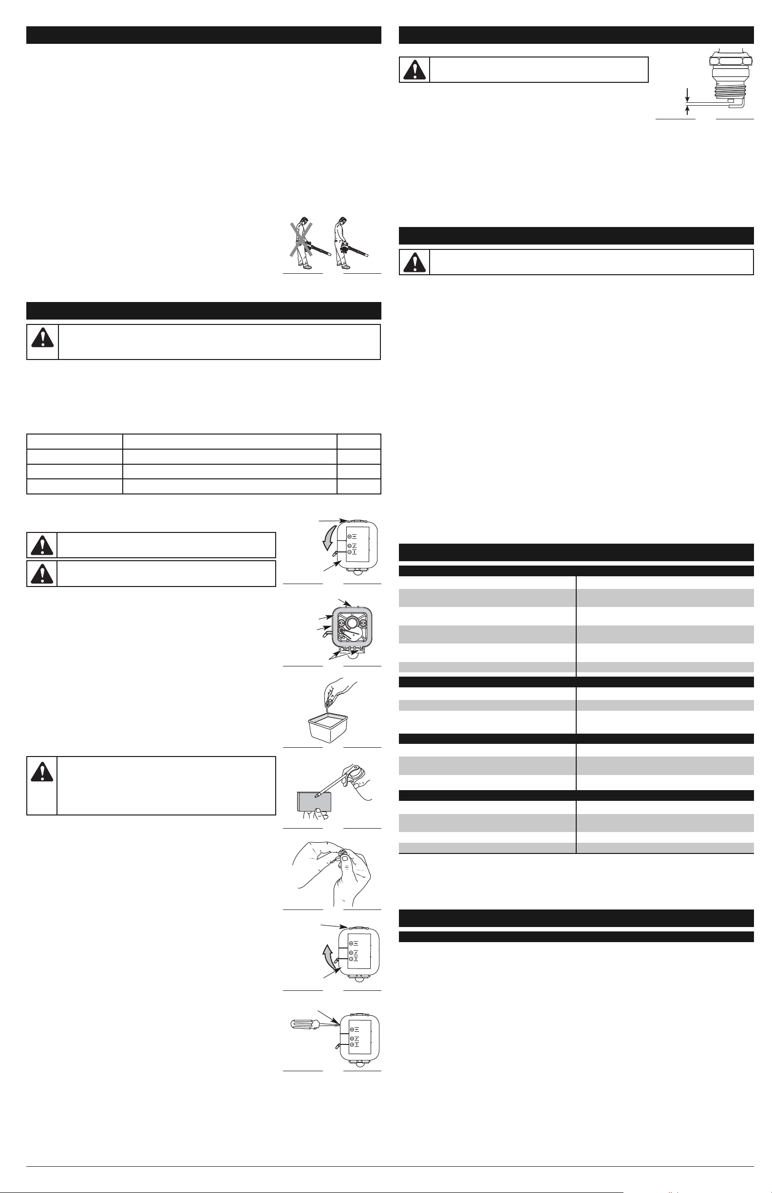
8
NETTOYAGE
Utilisez une petite brosse pour nettoyer l’extérieur de l’appareil. N’utilisez pas de détergents agressifs. Des produits
d’entretien ménagers contenant des huiles aromatiques, telles que le pin ou le citron, et des solvants tels que le kérosène,
peuvent endommager le boîtier en plastique ou la poignée. Essuyez toute trace d'humidité avec un chiffon doux.
RANGEMENT
• N’entreposez jamais un appareil moteur à essence où les vapeurs peuvent entrer en contact avec toute source de
flammes ou d’étincelles.
• Laissez le moteur refroidir avant d’entreposer l’appareil.
• Gardez l’appareil sous clef pour éviter tout usage non autorisé et pour éviter qu’il soit endommagé.
• Entreposez l’appareil dans un endroit sec et bien aéré.
• Entreposez l’appareil hors de la portée des enfants.
ENTREPOSAGE À LONG TERME
Si vous comptez entreposer l'appareil pendant une longue période, suivez la procédure ci-dessous :
1. Videz toute l’essence du réservoir dans un récipient contenant le même mélange pour moteur 2 temps. N'utilisez
pas de carburant stocké pendant plus de 30 jours. Éliminez les restes de mélange de carburant conformément aux
réglementations locales, régionales et nationales en vigueur.
2. Démarrez le moteur et laissez-le tourner jusqu’à ce qu’il s’arrête par faute d’essence. Ceci vous assure que le
carburateur est bien vide.
3. Laissez refroidir le moteur. Retirez la bougie et versez 5 gouttes d’huile moteur de qualité dans le cylindre. Tirez
lentement sur le cordon de démarrage pour bien répartir l’huile. Remettez la bougie en place.
REMARQUE : Retirez la bougie et videz toute l’huile se trouvant dans le cylindre avant d’essayer de démarrer l’appareil
après l’entreposage.
4. Nettoyez soigneusement l’appareil et inspectez-le méticuleusement pour vérifier s’il n’y a pas de pièces détachées
ou endommagées. Réparez ou remplacez les pièces endommagées et serrez tous les boulons et vis desserrées.
L’appareil est prêt à être entreposé.
TRANSPORT
• Laissez le moteur refroidir avant de transporter l’appareil.
• Videz toute l’essence de l’appareil.
• Serrez le bouchon du réservoir d’essence avant de transporter l’appareil.
• Sécurisez l’appareil pour le transport.
CAUSE SOLUTION
Le carburant est vieux et/ou mal mélangé
Videz toute l’essence du réservoir et ajoutez un
carburant frais et correctement mélangé
Le filtre à air est bouché Nettoyez ou remplacez le filtre à air
La bougie d’allumage est encrassée Nettoyez, écartez ou remplacez la bougie d’allumage
CAUSE SOLUTION
Le carburant est vieux et/ou mal mélangé
Videz toute l’essence du réservoir et ajoutez un
carburant frais et correctement mélangé
Le filtre à air est bouché Nettoyez ou remplacez le filtre à air
CAUSE SOLUTION
Le réservoir d’essence est vide
Remplissez le réservoir d’essence avec du carburant
correctement mélangé
La poire d’amorçage n’a pas été suffisamment pressée
Pressez la poire d’amorçage lentement et
complètement, 10 fois de suite
Le moteur est noyé
Placez le levier d’étranglement en position 3, pressez la
gâchette et tirez sur le cordon de démarrage
Le carburant est vieux et/ou mal mélangé
Videz toute l’essence du réservoir et ajoutez un
carburant frais et correctement mélangé
La bougie d’allumage est encrassée Nettoyez, écartez ou remplacez la bougie d’allumage
CAUSE SOLUTION
Le filtre à air est bouché Nettoyez ou remplacez le filtre à air
Le carburant est vieux et/ou mal mélangé
Videz toute l’essence du réservoir et ajoutez un
carburant frais et correctement mélangé
RÉSOLUTION DES PROBLÈMES
LE MOTEUR NE DÉMARRE PAS
LE MOTEUR NE TOURNE PAS AU RALENTI
LE MOTEUR N’ACCÉLÈRE PAS
REMARQUE : Pour des réparations au-delà des petits réglages mentionnés ci-dessus, veuillez appeler le service à la
clientèle au 1-877-282-8684 (E.U.) ou 1-800-668-1238 (Canada) pour connaître le professionnel agréé le
plus proche de chez vous.
LE MOTEUR MANQUE DE PUISSANCE OU CALE
MOTEUR*
Type de moteur. . . . . . . . . . . . . . . . . . . . . . . . . . . . . . . . . . . . . . . . . . . . . . . . . . . . . . . 2 temps, à refroidissement par air
Cylindrée . . . . . . . . . . . . . . . . . . . . . . . . . . . . . . . . . . . . . . . . . . . . . . . . . . . . . . . . . . . . . . . . . . . . . . . . . . . . . . . . . . 27 cc
Régime au ralenti . . . . . . . . . . . . . . . . . . . . . . . . . . . . . . . . . . . . . . . . . . . . . . . . . . . . . . . . . . . . . . . . . 3 600–4 200 t/min
Régime de fonctionnement . . . . . . . . . . . . . . . . . . . . . . . . . . . . . . . . . . . . . . . . . . . . . . . . . . . . . . . . . . 6 800–4 200 t/min
Vitesse de soufflage . . . . . . . . . . . . . . . . . . . . . . . . . . . . . . . . . . . . . . . . . . . . . . . . . . . . . . . . . . . . . 241 km/h (150 mi/h)
Débit d’air . . . . . . . . . . . . . . . . . . . . . . . . . . . . . . . . . . . . . . . . . . . . . . . . . . . . . . . . . . . . . . . 14,15 cm3/min (500 pi³/min)
Type d’allumage . . . . . . . . . . . . . . . . . . . . . . . . . . . . . . . . . . . . . . . . . . . . . . . . . . . . . . . . . . . . . . . . . . . . . . . Électronique
Interrupteur d’allumage . . . . . . . . . . . . . . . . . . . . . . . . . . . . . . . . . . . . . . . . . Interrupteur à rappel marche/arrêt (On/Off)
Écartement de la bougie d’allumage . . . . . . . . . . . . . . . . . . . . . . . . . . . . . . . . . . . . . . . . . . . . . . . . 0,635 mm (0,025 po)
Lubrification . . . . . . . . . . . . . . . . . . . . . . . . . . . . . . . . . . . . . . . . . . . . . . . . . . . . . . . . . . . . . . . . . . Mélange huile/essence
Rapport essence/huile . . . . . . . . . . . . . . . . . . . . . . . . . . . . . . . . . . . . . . . . . . . . . . . . . . . . . . . . . . . . . . . . . . . . . . . . 40:1
Carburateur . . . . . . . . . . . . . . . . . . . . . . . . . . . . . . . . . . . . . . . . . . . . . . . . . . . . . . . . . . . . . Diaphragme, toutes positions
Démarreur . . . . . . . . . . . . . . . . . . . . . . . . . . . . . . . . . . . . . . . . . . . . . . . . . . . . . . . . . . . Avec enroulage automatique AST
Pot d’échappement . . . . . . . . . . . . . . . . . . . . . . . . . . . . . . . . . . . . . . . . . . . . . . . . . . . . Compartimenté avec protection
Accélérateur. . . . . . . . . . . . . . . . . . . . . . . . . . . . . . . . . . . . . . . . . . . . . . . . . . . . . . . . . . . . . . . . . . . . . . . . Vitesse variable
Capacité du réservoir d’essence . . . . . . . . . . . . . . . . . . . . . . . . . . . . . . . . . . . . . . . . . . . . . . . . . . . . . . . . 414 ml (14 oz)
Poids approximatif (réservoir vide) . . . . . . . . . . . . . . . . . . . . . . . . . . . . . . . . . . . . . . . . . . . . . . . . . . . . . . . 5,44 kg (12 lb)
SPÉCIFICATIONS
* L’ensemble des caractéristiques sont basées sur les toutes dernières informations disponibles sur le produit à l’impression
de ce guide. Nous nous réservons le droit d’effectuer des modifications à tout moment sans notification préalable.
AVERTISSEMENT :
Afin d’éviter des blessures graves, arrêtez toujours l’appareil et laissez-le
refroidir avant tout nettoyage ou entretien.
NETTOYAGE ET RANGEMENT
REMPLACEMENT DE LA BOUGIE D’ALLUMAGE
Utilisez une bougie 753-05784. L'écartement correct est de 0,635 mm (0,025 po).
Retirez la bougie toutes les 25 heures d’utilisation et vérifiez son état.
1. Arrêtez le moteur et laissez-le refroidir.
2. Saisissez fermement la coiffe de la bougie et retirez le capuchon de la bougie.
3. Nettoyez bien l’espace autour de la bougie. Dévissez la bougie de la tête du
cylindre à l’aide d’une douille de 5/8 po en tournant vers la gauche.
4. Remplacez toute bougie fendue, encrassée ou sale. Réglez l’écartement des électrodes à 0,635 mm (0,025 po) à
l’aide d’une jauge d’épaisseur (Fig. 19).
5. Installez une bougie à l’écartement correct dans la tête du cylindre. Tournez la douille de 5/8 po vers la gauche
jusqu’à ce qu’elle soit bien serrée.
Si vous utilisez une clé dynamométrique, mettez le couple de serrage à :
12,3-13,5 N•m (110-120 in.•lb.).
Ne serrez pas trop fort.
6. Remettez la coiffe de bougie en place.
ENTRETIEN ET RÉPARATIONS
ENTRETIEN ET RÉPARATIONS
PROGRAMME D’ENTRETIEN
Effectuez ces procédures d’entretien obligatoires aux fréquences indiquées dans le tableau d’entretien. Ces
procédures devraient également avoir lieu lors de toute révision de début de saison.
REMARQUE : Certaines procédures d’entretien peuvent nécessiter des outils ou compétences spécifiques. Si vous
n’êtes pas certain d’être capable de les effectuer, apportez l’appareil chez un revendeur Cub Cadet ou un
concessionnaire agréé.
REMARQUE : L’entretien, le remplacement ou la réparation des dispositifs et systèmes de commande peuvent être
effectués chez un revendeur Cub Cadet ou un concessionnaire agréé.
AVERTISSEMENT :
Afin d’éviter les blessures graves, n’effectuez jamais de réparation ou
n’entretenez jamais l’appareil lorsqu’il est en fonctionnement. Les réparations et l’entretien doivent
toujours être effectués lorsque l’appareil est froid. Déconnectez le fil de la bougie pour vous assurer que
l’appareil ne se mette pas en marche.
FRÉQUENCE ENTRETIEN REQUIS VOIR
Avant de démarrer le moteur Remplissez le réservoir de carburant avec un mélange essence/huile frais* p. 7
Toutes les 10 heures Nettoyez et appliquez de l’huile sur le filtre à air p. 8
Toutes les 25 heures Vérifiez l’état de la bougie ainsi que l’espacement de cette dernière p. 8
* N’utilisez PAS d’essence E85 dans cet appareil. Il a été prouvé que l’utilisation de carburant contenant plus de 15 %
d’éthanol endommagera très certainement ce moteur et annulera la garantie.
INSTRUCTIONS D’UTILISATION
Autres conseils
• Assurez-vous que l’appareil n’est pas dirigé vers une personne ou des débris non sécurisés avant de démarrer l’appareil.
• Vérifiez que l’appareil est en bon état de marche. Assurez-vous que tous les tubes sont en place et solidement fixés.
• Tenez toujours l’appareil bien en main lorsque vous l’utilisez. Tenez fermement la poignée.
• Pour diminuer le risque de perte d'audition due au niveau sonore, portez toujours une protection auditive lorsque
vous utilisez cet appareil.
• Utilisez les outils à moteur uniquement à des heures raisonnables, non pas tôt le matin ou tard le soir à des heures
susceptibles de déranger le voisinage. Conformez-vous aux horaires indiqués par les autorités locales
(généralement de 9h00 à 17h00, du lundi au samedi).
• Pour réduire le niveau sonore, limitez le nombre d’appareils utilisés en même temps.
• Pour réduire le niveau sonore, utilisez le souffleur à la vitesse la plus basse possible pour effectuer le travail.
• Contrôlez votre matériel avant l'utilisation, en particulier le pot d'échappement, les entrées d'air et les filtres.
• Désagrégez grossièrement les débris à l’aide de râteaux et de balais avant d'utiliser le souffleur.
• Dans des conditions poussiéreuses, humidifiez légèrement les surfaces ou utilisez un accessoire humidificateur si
de l’eau est disponible.
• Économisez l’eau en utilisant des souffleurs plutôt que les tuyaux d’arrosage pour différents travaux de jardin et de
pelouse, tels que les caniveaux, les grillages, les terrasses, les grilles, les auvents et les jardins.
• Faites attention aux enfants, animaux domestiques, fenêtres ouvertes, voitures qui viennent d’être lavées et
soufflez les débris en toute sécurité.
• Nettoyez après avoir utilisé le souffleur ou d’autres appareils. Éliminez les débris de
façon appropriée.
• Utilisez le souffleur autour des arbres, des arbustes, des parterres de fleurs et des
zones difficiles à nettoyer. Utilisez-le également pour nettoyer autour des
bâtiments, des murs, des parties en surplomb, des clôtures et des grillages et
pour d’autres tâches habituelles de nettoyage.
• Tenez le souffleur de la main droite. Ne vous placez pas à droite du souffleur lorsque
vous utilisez l’appareil (Fig. 11). Si vous le faites, vous bloquerez l’entrée d’air et cela
peut avoir des conséquences sur les performances de l’appareil. Placez-vous plutôt
du côté gauche de l’appareil pour optimiser son efficacité (Fig. 11).
Fig. 11
POSITION
INCORRECTE
POSITION
CORRECTE
ENTRETIEN DU FILTRE A AIR
Nettoyage du filtre à air
Nettoyez et appliquez de l’huile sur le filtre à air toutes les 10 heures d’utilisation. Son
entretien est essentiel : Tout manquement à sons entretien peur entraîner une baisse
de performance ou des dégâts permanents au moteur.
1. Ouvrez le couvercle du filtre à air. Poussez sur la languette de verrouillage située
sur la partie supérieure du couvercle, puis tirez sur le couvercle du filtre à air en
l’orientant vers l’extérieur et le bas. (Fig. 12).
2. Retirez le filtre à air (Fig.13).
3. Lavez le filtre avec du détergent et de l’eau (Fig. 14). Rincez-le soigneusement et
laissez-le sécher.
4. Appliquez suffisamment d’huile lubrifiante pour moteur SAE 30 afin de recouvrir le
filtre d’une fine couche (Fig. 15).
5. Pressez le filtre pour répartir et enlever l’excédent d'huile (Fig. 16).
6. Remettez le filtre en place (Fig. 13).
REMARQUE : L’utilisation de l’appareil sans le filtre à air ANNULERA la garantie.
7. Remettez le couvercle du filtre à air en place. Positionnez les encoches dans la
partie inférieure du couvercle du filtre à air sur les languettes sur la partie
inférieure de la plaque arrière (Fig. 13).
8. Faites pivoter le couvercle jusqu’à ce que la languette sur la plaque arrière du filtre
à air se loge dans l’encoche sur le couvercle du filtre à air (Fig. 17).
RÉGLAGE DU CARBURATEUR
Il est possible de régler la vitesse de ralenti de l’appareil. Une vis de réglage du ralenti
se trouve entre le couvercle du filtre à air et le couvercle du moteur (Fig. 18).
REMARQUE : Un mauvais réglage peut sérieusement endommager votre appareil.
Le réglage du carburateur doit être confié à un concessionnaire agrée.
Vérifiez le mélange de carburant
L’utilisation de vieux carburant est souvent à l’origine de mauvaises performances de
l’appareil. Videz le réservoir et remplissez-le avec un mélange huile/essence frais avant de
procéder à tout réglage. Consultez les Informations sur l’huile et le carburant.
Nettoyez le filtre à air
L’état du filtre à air est important pour le bon fonctionnement de l’appareil. Un filtre à
air sale limitera le flux d’air. Ceci est souvent confondu avec un carburateur déréglé.
Vérifiez l’état du filtre à air avant de régler la vis de ralenti du moteur. Consultez la
section Entretien du filtre à air.
Ajustez la vis de réglage du ralenti
Si, après avoir vérifié le niveau de carburant et nettoyé le filtre à air, le moteur ne
tourne toujours pas au ralenti, ajustez la vis de réglage du ralenti comme suit :
1. Démarrez le moteur et laissez-le tourner à une vitesse supérieure à celle du ralenti
pendant une minute environ pour que le moteur se réchauffe. Consultez les
Instructions de démarrage et d’arrêt.
2. Relâchez la manette des gaz et laissez tourner le moteur au ralenti. Si le moteur s’arrête,
insérez un petit tournevis cruciforme entre le couvercle du filtre à air et le couvercle du
moteur (Fig. 18). Tournez la vis de réglage du ralenti vers la droite, 1/8 de tour à la fois
(si nécessaire), jusqu’à ce que le moteur tourne au ralenti de façon régulière.
La vérification du niveau de carburant, le nettoyage du filtre à air et le réglage de la
vitesse de ralenti devraient résoudre la plupart des problèmes du moteur. Dans le cas
contraire et en présence des symptômes suivants :
• le moteur ne tourne pas au ralenti
• le moteur hésite et cale lors de l’accélération
• il y a une perte de puissance moteur
Faites ajuster le carburateur par un technicien agrée.
AVERTISSEMENT :
Afin d’éviter des blessures graves, arrêtez
toujours l’appareil et laissez-le refroidir avant tout nettoyage ou entretien.
AVERTISSEMENT : Portez des gants lorsque l’appareil est
utilisé afin d’éviter des blessures.
AVERTISSEMENT :
Le moteur de l’appareil doit tourner pour ajuster
le ralenti. Portez des vêtements de sécurité et respectez toutes les
consignes pour éviter des blessures graves. Ne posez l’appareil QUE sur
une surface propre et dure lorsque vous démarrez ou faites des
ajustements. Les débris tels que le gravier, le sable, la poussière, l’herbe,
etc. pourraient être projetés par le tube du souffleur et causer des dégâts
matériels ou blesser l’utilisateur ou les personnes se trouvant à proximité.
ATTENTION :
Ne jamais gratter, sabler ou nettoyer les électrodes.
Des saletés dans le moteur pourraient endommager le cylindre.
Fig. 12
Languette de
verrouillage
Couvercle
du filtre à air
Fig. 13
Languette de
verrouillage
Languettes
Fig. 14
Fig. 15
Fig. 17
Languette de
verrouillage
Couvercle
du filtre à air
Fig. 18
Vis de réglage
du ralenti
Filtre à air
Plaque
arrière
Fig. 19
0,635 mm
(0,025 po)
Fig. 16
Page 9

¿NECESITA AYUDA? LLAME AL 1-877-282-8684 EN EE. UU.,
O AL 1–800–668–1238 EN CANADÁ
PART NO. 769-05636 P00 (07/10)
HB227
Sopladora con
motor de gasolina
de 2 tiempos
Español — Page 9 English — Page 1Français — Page 5
Manual del Operador
Sacar la unidad de su cartón
11 2
Sacar todo el contenido del
cartón.
Ensamblar la unidad
Tub o
5
Gire la boquilla a la derecha
hasta que quede apretada.
Arrancar la unidad
Pera del
cebador
Boquilla
Ensamblar la unidad
Salida
Tub o
Ranura
Saliente
Inserte el saliente del tubo
de la sopladora en la
ranura de la salida.
40:1
1 Gallon 3,2 oz
6 7
Mezcle bien en un recipiente
de combustible aparte:
– 3.2 onzas líquidas de
aceite para motor de 2
tiempos
– 1 galón de gasolina sin
plomo
NOTA: No haga directamente
la mezcla en el tanque de
combustible.
Palanca del
obturador
Salida
3
Gire el tubo de la sopladora
a la derecha hasta que trabe
en su sitio.
Coloque la unidad sobre
una superficie plana.
Llene el tanque de
combustible.
Tub o
Tub o
Boquilla
Saliente
4
Inserte el saliente del otro
extremo del tubo de la
sopladora en la ranura de la
boquilla.
Ranura
¡No se necesitan herramientas!
Manija
Control de encendido/
apagado de parada
Control de crucero
Tubo de la sopladora
Boquilla
Palanca del
obturador
Palanca del
obturador
Pera del
cebador
Gatillo
Cuerda de
arranque
Tapa del tanque
de combustible
10 X
18 9
Presione la pera del
cebador 10 veces o hasta
que se vea el combustible.
Arrancar la unidad
Palanca del
obturador
115 16
Siga apretando el
regulador. Mueva la
palanca del obturador a la
Posición 3.
Mueva la palanca del
obturador a la Posición 1.
Siga apretando el
regulador. Deje funcionando
la unidad otros 60 segundos
para calentarla por completo.
La unidad se puede usar en
este momento.
10
OPRIMA y MANTENGA
OPRIMIDO el regulador en
TODOS los pasos
siguientes.
11
Agáchese en la posición de
arranque.
¿Necesita ayuda?
Llame al 1-877-282-8684
¿NO ARRANCÓ?
Repita estas instrucciones.
SI después de 2 intentos de arranque el motor no
reacciona, mueva la palanca del obturador a la
posición 3 y tire de la cuerda de arranque hasta que el
SI a pesar de ello la unidad no arranca, busque en el
manual del operador más información en cuanto al
motor eche a andar.
arranque y la solución de problemas.
5 X
12
Tire de la cuerda de
arranque 5 veces.
13
Mueva la palanca del
obturador a la Posición 2 y
oprima el regulador.
14
Tire de la cuerda de 3 a 5
veces para arrancar el
motor. Deje funcionar la
unidad de 30 a 60
segundos para calentarla.
3-5 X
IMPORTANTE: LEA BIEN EL MANUAL DEL OPERADOR Y, AL OPERAR LA UNIDAD, SIGA LAS INSTRUCCIONES PARA EL FUNCIONAMIENTO SEGURO.
Page 10

10
• Aleje a los niños, personas presentes y animales domésticos. Como mínimo, mantenga a todos los
niños, personas presentes y animales domésticos fuera de un radio de 50 pies (15 m); aún así, es
posible que los presentes se arriesguen al impacto de objetos despedidos. Debe sugerir a los
presentes que usen protección para los ojos. Si alguien se le acerca, pare la unidad de inmediato.
AVISOS DE SEGURIDAD PARA LAS UNIDADES QUE TRABAJAN CON GASOLINA
• Almacene el combustible solamente en los recipientes diseñados y aprobados específicamente
para estos materiales.
• Pare siempre el motor y deje que se enfríe antes de llenar el tanque de combustible. No quite
nunca la tapa del tanque de combustible ni eche combustible cuando el motor esté caliente. Antes
de llenar el tanque, afloje siempre la tapa lentamente para disipar la presión del mismo. No fume.
• Eche siempre el combustible en un área exterior bien ventilada y limpia, donde no haya chispas ni
llamas expuestas. No fume.
• No opere nunca la unidad si la tapa del combustible no está bien asegurada en su lugar.
• Evite el peligro de incendio debido a combustible derramado. Limpie de inmediato todo combustible
derramado de la unidad antes de encenderla. Antes de arrancar el motor, aleje la unidad a una
distancia de 30 pies (9.1 m) como mínimo del lugar de abasto de combustible. No fume.
• No arranque ni use nunca la unidad dentro de una habitación o edificio cerrados. Respirar los
vapores de escape puede ocasionarle la muerte. Opere esta unidad solamente en un área exterior
bien ventilada.
DURANTE EL FUNCIONANDO
• Use espejuelos o gafas de seguridad que estén marcados como que cumplen con las normas
ANSI Z87.1-1989. Use también protección para los oídos al operar esta unidad.
• No opere nunca la unidad sin haber conectado los equipos adecuados.
• Para reducir el riesgo de pérdida de la audición relacionada con el o los niveles de ruido, use
siempre protección para los oídos al operar esta unidad.
• Use pantalones largos y gruesos, botas, guantes y camisa de mangas largas. No use ropa holgada,
alhajas, pantalones cortos, sandalias ni esté descalzo. Asegure su cabello por encima del nivel de
los hombros.
• Para evitar una descarga de electricidad estática, no lleve puestos guantes de goma ni otros
guantes aislantes al operar esta unidad.
• Use la unidad únicamente a la luz del día o con buena luz artificial.
• Mantenga todas las superficies libres de aceite y combustible.
• Evite los arranques accidentales. Debe estar en la posición de arranque siempre que tire de la
cuerda. El operador y la unidad deben estar en una posición estable durante el arranque. Consulte
las Instrucciones de arranque y parada.
• Mientras el motor esté funcionando, no coloque el equipo sobre ninguna superficie, excepto un
área limpia y sólida. La toma de aire pudiera recoger residuos tales como gravilla, arena, polvo,
hierba, etc., los que luego serían lanzados por la abertura de descarga, dañando de esta forma la
unidad, la propiedad u ocasionar lesiones graves a las personas presentes o al operador.
• Use la herramienta correcta. Use esta herramienta solamente para el propósito previsto.
• No fuerce la unidad. El equipo funcionará mejor y con menos probabilidad de accidentes a la
velocidad para la que fue diseñado.
• No intente alcanzar demasiado lejos ni lo use parado en superficies inestables como escaleras, árboles,
pendientes pronunciadas, techos, etc. Mantenga siempre una posición y equilibrio adecuados.
• Sostenga siempre la unidad con firmeza cuando esté funcionando.
• Mantenga las manos, la cara y los pies lejos de todas las partes móviles. No toque ni trate de detener
el impelente cuando esté girando. No opere la unidad sin tener los protectores instalados.
• No ponga ningún objeto en las aberturas. No opere la unidad si alguna de las aberturas está
obstruida; manténgala sin suciedad, residuos y cualquier otra cosa que pueda reducir el flujo de aire.
• No toque el motor ni el silenciador. Estas partes se calientan mucho durante el funcionamiento y se
mantienen así aun después de apagada la unidad.
• No opere el motor a una velocidad mayor que la necesaria para el trabajo. No ponga a funcionar el
motor a alta velocidad si no lo está usando.
• Apague siempre el motor cuando la operación se demore o al caminar de un lugar a otro.
• Apague el motor para su mantenimiento, reparaciones o para instalar o quitar los tubos de la sopladora.
Para evitar el contacto con las aspas giratorias, se debe parar la unidad y esperar a que el impelente no
dé más vueltas.
• Si golpea o se enreda con un objeto extraño, pare inmediatamente el motor y busque si hay daño. No
ponga a funcionar el equipo antes de reparar el daño. No opere la unidad si tiene piezas flojas o dañadas.
• Utilice solamente las piezas de repuesto recomendados para esta herramienta que venda un
distribuidor Cub Cadet. Usar cualquier pieza de repuesto comprada en otra parte puede ser
peligroso y, además, anulará su garantía.
• No use nunca esta unidad para rociar productos químicos, fertilizantes ni otras sustancias que
puedan contener materiales tóxicos.
• Para evitar el peligro de incendio, reemplace el silenciador y parachispas defectuosos. Mantenga el
motor y el silenciador sin hierbas, hojas, grasa excesiva ni incrustación de carbón.
• Apague el motor y desconecte la bujía para el mantenimiento o reparación.
• No apunte nunca la sopladora ni los residuos hacia las personas, animales o contra las ventanas.
Dirija siempre los residuos lejos de las personas, animales y ventanas. Tenga mucho cuidado al
soplar los residuos cerca de objetos masivos como árboles, automóviles, paredes, etc.
OTRAS ADVERTENCIAS DE SEGURIDAD
• Antes de llevar a cabo el mantenimiento o acceder a las piezas movibles, desconecte siempre la bujías.
• No guarde nunca la unidad con combustible en el tanque ni dentro de una edificación en la que los
gases puedan ponerse en contacto con una llama expuesta (luces pilotos, etc.) o chispas
(interruptores, motores eléctricos, etc.).
• Espere a que el motor se enfríe para guardar o transportar la unidad. Cerciórese de que la unidad esté
segura al transportarla.
• Guarde la unidad en un lugar seco, ya sea bajo llave o en alto, a fin de evitar su uso no autorizado o daño.
Manténgala fuera del alcance de los niños.
• No moje nunca ni rocíe la unidad con agua ni con ningún otro líquido. Mantenga las manijas secas,
limpias y sin residuos. Limpie la unidad después de cada uso; consulte las Instrucciones de
Limpieza y almacenamiento.
• Conserve estas instrucciones. Consúltelas con frecuencia y utilícelas para enseñar a otros usuarios. Si
le presta esta unidad a alguien, préstele también estas instrucciones.
NOTA ESPECIAL: La exposición a las vibraciones por el uso prolongado de herramientas manuales
con motores de gasolina podría ocasionar daños a las venas o nervios de los dedos, manos y
articulaciones de personas propensas a problemas circulatorios o inflamaciones atípicas. Su uso
prolongado en climas fríos se ha relacionado con daños a las venas de otras personas, de lo contrario,
sanas. Si se presentaran síntomas como entumecimiento, dolor, pérdida de fuerza, cambios en el color
o textura de la piel o pérdida de sensibilidad en los dedos, las manos o articulaciones, suspenda el uso
de la herramienta y busque atención médica. Un sistema anti vibratorio no garantizaría evitar estos
problemas. Los usuarios que operan habitualmente herramientas motorizadas deben monitorear de
cerca su estado de salud y las condiciones de la herramienta.
GUARDE ESTAS INSTRUCCIONES
INFORMACIÓN DE SEGURIDAD
NOTA SOBRE EL PARACHISPAS
NOTA: Para usuarios de la Zona Forestal de EE. UU., y los estados de California, Maine, Oregón
y Washington. Todas las Zonas Forestales de EE. UU., así como los estados de California (Códigos de
Recursos Públicos 4442 y 4443), Oregón y Washington exigen, por ley, que determinados motores de
combustión interna operados en matorrales boscosos y/o zonas cubiertas de hierba, estén equipados
con un parachispas y se mantengan en buen estado de funcionamiento, o que el motor sea construido,
equipado y mantenido con vista a la prevención de incendios. Compruebe con sus autoridades estatales
o locales las regulaciones relacionadas con estos requisitos. Si no cumple estos requisitos podría estar
sujeto a responsabilidad civil o multa. Esta unidad viene equipada de fábrica con un parachispas.
Si necesita reemplazarlo, pídale a su DISTRIBUIDOR DE SERVICIO LOCAL instalarle la Pieza Accesorio
#753-06027 del ensamblaje del silenciador.
LEA TODAS LAS INSTRUCCIONES ANTES DE OPERAR LA UNIDAD
• Lea las instrucciones detenidamente. Familiarícese con los controles y el uso adecuado de la unidad.
• No opere esta unidad si está cansado, enfermo o bajo los efectos del alcohol, drogas o medicamentos.
• Los niños y adolescentes menores de 15 años no deben usar la unidad. Los adolescentes pueden
hacerlo bajo la supervisión de un adulto.
• Todos los accesorios de protección y seguridad deben estar instalados adecuadamente antes de
comenzar a operar la unidad.
• Inspeccione la unidad antes de utilizarla. Cambie las piezas dañadas. Verifique que no haya fugas de
combustible. Asegúrese de que todos los sujetadores estén colocados y asegurados. Cambie las piezas
rajadas, melladas o dañadas de cualquier forma. No opere la unidad si tiene piezas flojas o dañadas.
• Inspeccione cuidadosamente el área antes de encender la unidad. Elimine todos los escombros y
los objetos duros o filosos tales como cristales, alambres, etc.
• INSTRUCCIONES IMPORTANTES DE SEGURIDAD •
INFORMACIÓN SOBRE SERVICIO
TABLA DE CONTENIDO
Información sobre servicio . . . . . . . . . . . . . . . . . . . . . . . . . . . . . . . . . . . . . . . . . . . . . . . . . . . . . . . . .10
Información de seguridad . . . . . . . . . . . . . . . . . . . . . . . . . . . . . . . . . . . . . . . . . . . . . . . . . . . . . . . . . .10
Conozca su unidad . . . . . . . . . . . . . . . . . . . . . . . . . . . . . . . . . . . . . . . . . . . . . . . . . . . . . . . . . . . . . . .11
Instrucciones de ensamblaje . . . . . . . . . . . . . . . . . . . . . . . . . . . . . . . . . . . . . . . . . . . . . . . . . . . . . . .11
Información sobre aceite y combustible . . . . . . . . . . . . . . . . . . . . . . . . . . . . . . . . . . . . . . . . . . . . . .11
Instrucciones de arranque y parada . . . . . . . . . . . . . . . . . . . . . . . . . . . . . . . . . . . . . . . . . . . . . . . . . .11
Instrucciones de operación . . . . . . . . . . . . . . . . . . . . . . . . . . . . . . . . . . . . . . . . . . . . . . . . . . . . . . . .11
Instrucciones de mantenimiento y reparación . . . . . . . . . . . . . . . . . . . . . . . . . . . . . . . . . . . . . . . . . .12
Limpieza y almacenamiento . . . . . . . . . . . . . . . . . . . . . . . . . . . . . . . . . . . . . . . . . . . . . . . . . . . . . . . .12
Localización y solución de problemas . . . . . . . . . . . . . . . . . . . . . . . . . . . . . . . . . . . . . . . . . . . . . . . .12
Especificaciones . . . . . . . . . . . . . . . . . . . . . . . . . . . . . . . . . . . . . . . . . . . . . . . . . . . . . . . . . . . . . . . . .12
Información sobre garantía . . . . . . . . . . . . . . . . . . . . . . . . . . . . . . . . . . . . . . . . . . . . . . . . . . . . . . . . .16
Toda la información, las ilustraciones y especificaciones que contiene este manual se basan en la
información más reciente del producto, existente en el momento de la impresión. Nos reservamos el
derecho de hacer cambios en cualquier momento sin previo aviso.
Copyright© 2010 MTD SOUTHWEST INC. Todos los derechos reservados.
NO DEVUELVA ESTA UNIDAD AL VENDEDOR. PARA SOLICITAR SERVICIO POR GARANTÍA,
DEBERÁ PRESENTAR EL COMPROBANTE DE COMPRA.
Para solicitar asistencia en relación con el ensamblaje, los controles, la operación o el mantenimiento
de la unidad, llame al Departamento de Atención al Cliente al 1-877-282-8684 en Estados Unidos o el
1-800-668-1238 en Canadá. Puede encontrar más información sobre la unidad en nuestro sitio Web
en www.cubcadet.com o www.cubcadet.ca.
Con vista a recibir servicios, llame al Departamento de Atención al Cliente para que le faciliten una
lista de los distribuidores de servicio autorizados cercanos a usted. El servicio a esta unidad, tanto
durante como después del período cubierto por la garantía, debe ser llevado a cabo solamente por
un distribuidor de servicio autorizado y aprobado. Cuando vaya a dar mantenimiento al equipo, utilice
solo piezas de repuesto idénticas.
Antes de llamar para recibir servicio, localice la placa correspondiente al modelo de la unidad, en la que se
indican el modelo y número de serie de su unidad. Remítase a la placa de ejemplo debajo y copie la
información para consultarla en el futuro.
Copie aquí el número de serie:
Copie aquí el modelo y los números de piezas del fabricante:
Lea el Manual del Operador y siga todas las advertencias e instrucciones de seguridad. No
hacerlo puede ocasionar lesiones graves al operador y/o a las personas presentes.
SI TIENE PREGUNTAS, LLAME AL 1-877-282-8684 EN EE. UU., O AL 1-800-668-1238 EN CANADÁ
ADVERTENCIA DE LA PROPOSICIÓN 65 DEL ESTADO DE CALIFORNIA
ADVERTENCIA
LOS GASES DE ESCAPE DEL MOTOR DE ESTE EQUIPO CONTIENEN PRODUCTOS QUÍMICOS
DE LOS QUE EL ESTADO DE CALIFORNIA TIENE CONOCIM IENTO PROVOCAN CÁNCER,
MALFORMACIONES CONGÉNITAS U OTROS DAÑOS AL SISTEMA REPRODUCTOR.
ADVERTENCIA: Al utilizar la unidad, debe seguir las normas de seguridad. Lea estas
instrucciones antes de operar la unidad a fin de garantizar la seguridad del operador y de
cualquier otra persona presente. Guarde estas instrucciones para poder usarlas más adelante.
ADVERTENCIA: La gasolina es sumamente inflamable y, de prenderse, sus vapores
pueden hacer explosión. Tome las siguientes precauciones:
INFORMACIÓN DE SEGURIDAD
• SÍMBOLOS DE ALERTA DE SEGURIDAD •
Los símbolos de alerta de seguridad se utilizan para llamar su atención sobre posibles peligros. Estos
símbolos y sus explicaciones merecen toda su atención y comprensión. Las advertencias de seguridad
no eliminan ningún peligro por sí mismas. Las instrucciones o advertencias que ofrecen no sustituyen a
las medidas adecuadas de prevención de accidentes. El objetivo de estas instrucciones de seguridad no
consiste en abarcar cada una de las posibles situaciones que puedan ocurrir. Si surgen preguntas, llame
al Departamento de Atención al Cliente al 1-877-282-8684 (EE. UU.) o al 1-800-668-1238 (Canadá).
PELIGRO: Indica un peligro EXTREMO.
El no obedecer una señal de PELIGRO TENDRÁ COMO CONSECUENCIA que usted u
otras personas puedan recibir lesiones graves o la muerte.
ADVERTENCIA: Indica un peligro GRAVE.
El no obedecer una señal de ADVERTENCIA de seguridad PUEDE provocar que usted u
otras personas sufran graves lesiones.
PRECAUCIÓN: Indica un peligro MODERADO.
El no obedecer una señal de PRECAUCIÓN de seguridad PUEDE provocar daños a la
propiedad o que usted u otras personas se lesionen.
¡IMPORTANTE! Indica información mecánica especial.
NOTA: Indica información general importante adicional.
SÕMBOLO SIGNIFICADO
• SÍMBOLOS INTERNACIONALES Y DE SEGURIDAD •
Este manual del operador describe símbolos y pictografías internacionales y de seguridad que posiblemente
aparezcan en este producto. Lea el manual del operador a fin de informarse bien sobre la seguridad, el
ensamblaje, la operación, el mantenimiento y la reparación.
SÍMBOLO SIGNIFICADO
• SÍMBOLO DE ALERTA DE SEGURIDAD
Indica peligro, advertencia o precaución. Puede utilizarse junto a otros símbolos o
pictografías.
• LEA EL MANUAL DEL OPERADOR
ADVERTENCIA: Lea el o los manuales del operador y siga todas las advertencias e
instrucciones de seguridad. No hacerlo puede ocasionar lesiones graves al operador y/o a
las personas presentes.
• USE PROTECCIÓN PARA LOS OJOS Y OÍDOS
ADVERTENCIA: Los objetos que salen despedidos y el ruido fuerte pueden
ocasionar lesiones oculares severas y pérdida de la audición. Póngase gafas o lentes de
protección que cumplan las normas ANSI Z87.1-1989 y protección para los oídos
cuando opere esta unidad. De ser necesario, use un protector de cara entera.
• COMBUSTIBLE SIN PLOMO
Use siempre combustible limpio, fresco y sin plomo.
• ACEITE
Consulte el tipo de aceite adecuado en el manual del operador.
• NO USE COMBUSTIBLE E85 EN ESTA UNIDAD
ADVERTENCIA: Se ha comprobado que es probable que el combustible con más
de un 15% de etanol dañe este motor, lo que anulará la garantía.
MODEL :
S/N :
ITEM :
Page 11

11
INSTRUCCIONES PARA MEZCLAR EL ACEITE Y EL COMBUSTIBLE
Un combustible viejo y/o mal mezclado es la principal causa de que la unidad no funcione bien. Asegúrese de usar un
combustible fresco, limpio y sin plomo. Siga atentamente las instrucciones para mezclar adecuadamente el aceite/combustible.
Definición de combustibles mezclados
Los combustibles de hoy en día son, por lo regular, una mezcla de gasolina e hidrocarburos oxigenados como el
etanol, metanol o MTBE (éter). La gasolina mezclada con alcohol absorbe agua. Un 1% de agua es suficiente para
separar la mezcla de aceite y alcohol. Al guardarla, se forman ácidos. Si utiliza combustible mezclado con alcohol,
úselo siempre fresco (con menos de 30 días).
Uso de combustibles mezclados
Si opta por utilizar un combustible mezclado, o no puede utilizar otro, tenga en cuenta las precauciones recomendadas:
• Utilice siempre la mezcla fresca de combustible indicada en su manual del operador
• Agite siempre la mezcla de combustible antes de abastecer la unidad
• Drene el tanque y eche a andar el motor en seco antes de guardar la unidad
Uso de aditivos al combustible
La botella de aceite para motor de 2 tiempos que vino con su unidad contiene un aditivo que ayudará a inhibir la corrosión y
minimizará la formación de depósitos de goma. Se le recomienda que use nuestro aceite para motor de 2 tiempos en esta
unidad. Si no es posible, utilice un buen aceite para motores de 2 tiempos enfriados por aire elaborado con un aditivo como
el estabilizador de gasolina STA-BIL® o similar. Agregue 0.8 oz. (23 ml) de aditivo por galón de combustible según las
instrucciones del recipiente. No añada NUNCA los aditivos directamente en el tanque de combustible de la unidad.
Mezcle bien el aceite para motor de 2 tiempos con la gasolina sin plomo en la proporción correcta, en una lata aparte
para combustible. Use una proporción de combustible/aceite 40:1 No los mezcle directamente en el tanque de
combustible del motor. Vea en la tabla a continuación las proporciones específicas de las mezclas de gasolina y aceite.
NOTA: Un galón (3.8 litros) de gasolina sin plomo mezclado con una botella de 3.2 oz. (95 ml) de aceite para motores de 2
tiempos representa una proporción de combustible/aceite 40:1.
NOTA: Deseche la mezcla vieja de combustible/aceite conforme a las regulaciones federales, estatales y locales.
CONOZCA SU UNIDAD
Manija
ENSAMBLAR LA UNIDAD
Instalación del tubo de la sopladora
1. Alinee el saliente del extremo del tubo de la
sopladora con la ranura de tope del extremo
inferior de la salida de la sopladora (Fig. 1).
2. Inserte el saliente del tubo de la sopladora en
la ranura de tope de la salida de la sopladora
(Fig. 1).
3. Gire a la derecha el tubo de la sopladora
insertado en la salida de la sopladora hasta
que el saliente trabe en su lugar (Fig. 2).
Instalación de la boquilla
1. Alinee el saliente del extremo del tubo de la
sopladora con la ranura de tope del extremo
superior de la salida de la sopladora (Fig. 3).
2. Inserte el saliente del tubo de la sopladora en
la ranura de tope de la boquilla (Fig. 3).
3. Gire a la derecha la boquilla encima el tubo de
la sopladora hasta que quede apretada (Fig. 4).
Quitar el tubo de la sopladora
1. Sujete la unidad firmemente.
2. Inserte un destornillador plano en la traba del
tubo y dele 1/4 de vuelta a la izquierda,
sosteniéndolo en esa posición (Fig. 5).
3. Sin soltar el destornillador, sujete el tubo de la
sopladora y gírelo hacia la izquierda (Fig. 5).
4. Hale el tubo de la sopladora por la salida de la
sopladora.
Quitar la boquilla
1. Sujete firmemente el tubo de la sopladora.
2. Sujete la boquilla y gírela hacia la izquierda
hasta que la boquilla se destrabe del tubo de la sopladora (Fig. 6).
3. Saque la boquilla del tubo de la sopladora.
INSTRUCCIONES DE ENSAMBLAJE
ADVERTENCIA:
A fin de evitar lesiones personales graves y daños a la unidad, el tubo de la
sopladora y la boquilla deben ser instalados antes de poner en funcionamiento la unidad.
*ADVERTENCIA: NO USE COMBUSTIBLE E85 EN
ESTA UNIDAD.
Se ha comprobado que es probable que el
combustible con más de un 15% de etanol dañe este motor, lo que
anulará la garantía.
ADVERTENCIA: La gasolina es sumamente inflamable. De
prenderse, los vapores pueden hacer explosión. Detenga siempre el
motor y deje que se enfríe antes de llenar el tanque de combustible.
No fume mientras llena el tanque. Mantenga alejadas del área las
chispas y llamas expuestas.
PRECAUCIÓN:
Para el funcionamiento adecuado y máxima confiabilidad del motor, hay que prestar
rigurosa atención a las instrucciones para mezclar el aceite y el combustible que están en el recipiente del
aceite para motores de 2 tiempos. El uso de un combustible mal mezclado puede dañar seriamente el motor.
ADVERTENCIA:
Quite lentamente la tapa de combustible a fin
de evitar lesiones por salpicaduras. No opere nunca la unidad sin la
tapa del combustible colocada firmemente en su lugar.
INFORMACIÓN DEL ACEITE Y COMBUSTIBLE
SÍMBOLO SIGNIFICADO
• CONTROL DE ENCENDIDO/APAGADO DE PARADA
ENCENDIDO / ARRANQUE / EN MARCHA
• CONTROL DE ENCENDIDO/APAGADO DE PARADA
APADADO o PARADA
• PERA DEL CEBADOR
Oprima lentamente y por completo la pera del cebador 10 veces.
• CONTROL DE OBTURACIÓN
1. • Posición COMPLETA del obturador
2. • Posición PARCIAL del obturador
3. • Posición de FUNCIONAMIENTO del obturador
• LOS OBJETOS QUE SALEN DESPEDIDOS PUEDEN OCASIONAR LESIONES
GRAVES
ADVERTENCIA: Los objetos pequeños pueden ser lanzados a gran velocidad y
ocasionar lesiones.
• MANTENGA ALEJADOS A LOS PRESENTES
ADVERTENCIA:
Mantenga a todos los presentes, especialmente a los niños y
animales domésticos, a una distancia de al menos 50 pies (15 m).
• SUPERFICIE CALIENTE
ADVERTENCIA:
No toque nunca un motor caliente. Estas partes se ponen
extremadamente calientes durante el funcionamiento y pueden ocasionar graves
quemaduras. Después de apagada la unidad, el motor se mantendrá caliente durante un rato.
• SOPLADORAS – LA ASPAS GIRATORIAS DEL IMPELENTE PUEDEN OCASIONAR
LESIONES GRAVES
ADVERTENCIA:
Pare el motor y espere a que el impelente se detenga antes de
quitar o instalar los tubos o para limpiar o llevar a cabo cualquier mantenimiento.
ADVERTENCIA:
A fin de evitar lesiones personales graves y daños a la unidad, apague la unidad
antes de quitar el tubo de la sopladora y la boquilla.
INFORMACIÓN DE SEGURIDAD
Salida de la
sopladora
Tubo de la sopladora
Fig. 2
PROPORCIÓN - 40:1
GASOLINA SIN
PLOMO*
ACEITE PARA
MOTOR DE 2
TIEMPOS
1 GALÓN EE. UU.
(3.8 LITROS)
3.2 ONZAS
LÍQUIDAS
(95 ml)
1 LITRO 25 ml
+
APLICACIONES
Limpieza de patios, garajes, entrada de autos,
pórticos, terrazas, aceras, derredores de muros,
cercas y otros
Gatillo
Control de encendido/
apagado de parada
Control de
crucero
Bujía de
encendido
Tubo de la
sopladora
Boquilla
Cubierta del
silenciador
Tapa del
filtro de aire
Agarre de la cuerda
de arranque
Palanca del
obturador
Pera del cebador
Tapa del tanque
de combustible
Salida de la
sopladora
Ranura
de tope
Saliente
Fig. 1
Traba
del tubo
Salida de la sopladora
Tubo de la sopladora
Fig. 5
Boquilla
Tubo de la
sopladora
Fig. 4
Boquilla
Tubo de la
sopladora
Fig. 6
Tubo de la
sopladora
Saliente
Ranura
de tope
Fig. 3
Tubo
de la
sopladora
Boquilla
ADVERTENCIA:
Eche el combustible en un área exterior bien ventilada y limpia. Limpie de
inmediato todo el combustible derramado. Evite el peligro de incendio debido a combustible derramado.
No arranque el motor hasta que no se hayan disipado los vapores de combustible.
INSTRUCCIONES DE ARRANQUE
1. Mezcle la gasolina con el aceite. Llene el tanque de combustible con la mezcla de
combustible/aceite fresca. Consulte las Instrucciones para mezclar el aceite y el
combustible.
NOTA: No hay necesidad de arrancar la unidad. El interruptor de Encendido/Apagado
debe estar en la posición ENCENDIDO ( I ) en todo momento (Fig. 7).
2. Oprima lentamente y suelte por completo la pera del cebador 10 veces. Deberá verse
alguna cantidad de combustible en la pera del cebador (Fig. 7). Si no se ve
combustible en la pera, oprima y suelte la pera hasta que se vea el combustible.
3. Mueva la palanca del obturador a la Posición 1 (Fig. 8).
4. Apriete el gatillo y manténgalo apretado u oprima el control de crucero (Fig. 7).
5. Siga apretando el gatillo u oprimiendo el control de crucero. Coloque la
unidad en una superficie firme y plana. Agáchese en la posición de arranque y
sostenga la unidad firmemente (Fig. 9).
6. Siga apretando el gatillo u oprimiendo el control de crucero. Tire de la cuerda de
arranque hasta que sienta un poco de resistencia. Esto ocurre por lo general entre 2 y
4 pulgadas. Tire de la cuerda de arranque 5 veces con movimiento regulado y firme.
7. Siga apretando el gatillo u oprimiendo el control de crucero. Mueva la palanca
del obturador a la Posición 2 (Fig. 8).
8. Siga apretando el gatillo u oprimiendo el control de crucero. Tire de la cuerda
de arranque de 3 a 5 veces con movimiento regulado y firme para arrancar el motor.
9. Siga apretando el gatillo u oprimiendo el control de crucero. Deje que el
motor se caliente de 30 a 60 segundos.
10. Siga apretando el gatillo u oprimiendo el control de crucero. Mueva la palanca
del obturador a la Posición 3 (Fig. 8).
11. Siga apretando el gatillo u oprimiendo el control de crucero. Siga calentando
el motor otros 60 segundos. La unidad está lista para el uso.
SI... El motor no arranca, regrese al paso 2.
SI... El motor no arranca después de 2 intentos, mueva la palanca del obturador
a la Posición 3, apriete el gatillo y tire de la cuerda de arranque de 3 a 8
veces con movimiento regulado y firme. El motor debe arrancar. Si no arranca, repita las operaciones.
SI ESTÁ CALIENTE... Si el motor ya está caliente, mueva la palanca del obturador a la Posición 2, apriete el gatillo y
tire de la cuerda de arranque para repetir las operaciones.
INSTRUCCIONES DE PARADA
1. Suelte el gatillo o el control de crucero para que el motor se mantenga en ralentí.
2. Oprima y mantenga oprimido el interruptor de encendido/ apagado en la posición APAGADO (O) hasta que el
motor se detenga por completo (Fig. 7).
INSTRUCCIONES DE ARRANQUE Y PARADA
ADVERTENCIA: Evite los arranques accidentales. Cerciórese de estar en la posición de arranque al
tirar de la cuerda (Fig. 9). A fin de evitar lesiones graves, el operador y la unidad deben estar en una
posición estable durante el arranque. Para evitar lesiones personales graves, asegúrese de que los tubos
de la sopladora estén bien trabados en su sitio.
Control de
crucero
Interruptor de
Encendido/
Apagado
Pera del
cebador
Fig. 7
Cuerda de
arranque
Fig. 9
ADVERTENCIA: Opere esta unidad solamente en un área exterior bien ventilada. Las emanaciones de
escape de monóxido de carbono pueden ser letales en un lugar cerrado.
Fig. 8
Pera del
cebador
Posición 3
Palanca del
obturador
Gatillo
Gatillo
Posición de arranque
Posición 2
Posición 1
INSTRUCCIONES DE OPERACIÓN
SOSTENER LA SOPLADORA
Antes de poner a funcionar la unidad, párese en posición para operarla. Compruebe lo siguiente:
• El operador lleva puesta ropa adecuada como botas, espejuelos o gafas de protección, protección para los oídos,
guantes, pantalones largos y camisa de manga larga.
• Si la operación levanta polvo, el operador lleva puesta una máscara facial para protegerse.
• La unidad esté en buen estado de funcionamiento.
• Los tubos están en su sitio y asegurados.
RECOMENDACIONES DE OPERACIÓN
Usar el control de crucero
1. Una vez que el motor arranque y se caliente, apriete el gatillo para acelerar según
sea necesario (Fig. 10).
2. Para funcionamientos prolongados y eliminar la posibilidad de fatiga en el dedo, mueva el control de crucero a la
posición RÁPIDO ("FAST") a fin de aumentar poco a poco, o mantener, la velocidad del motor de la unidad (Fig.
10). Cuando oprima el control de crucero, el gatillo retrocederá hacia la manija.
3. Para disminuir la velocidad del motor, mueva el control de crucero a la posición LENTO ("SLOW") y el gatillo
regresará a la posición de ralentí (Fig. 10).
Fig. 10
ADVERTENCIA: Después de arrancar la unidad, para operarla, párese siempre a la izquierda de la
unidad como se muestra en la figura 11 a fin de no bloquear la entrada de aire.
ADVERTENCIA:
Para evitar lesiones personales graves, protéjase los ojos y los oídos siempre que
opere esta unidad. En lugares polvorientos, use una máscara contra polvo.
ADVERTENCIA:
A fin de evitar lesiones personales graves y
daños a la unidad, antes de operar la unidad, asegúrese de que el
tubo de la sopladora y la boquilla estén bien puestos.
LENTO
RÁPIDO
Control de
crucero
Gatillo
(posición de ralentí)
Page 12

12
LIMPIEZA
Use un cepillo pequeño para limpiar la parte exterior de la unidad. No utilice detergentes fuertes. Los limpiadores caseros
que contienen aceites esenciales, por ejemplo, de pino y limón, y los solventes como el queroseno pueden dañar el
cuerpo de plástico o la manija. Limpie la humedad con un paño suave.
ALMACENAMIENTO
• No guarde nunca la unidad con combustible en el tanque en un lugar en el que las emanaciones puedan ponerse
en contacto con una llama expuesta o chispas.
• Espere a que el motor se enfríe para guardar la unidad.
• Guarde la unidad bajo llave a fin de evitar su uso no autorizado o daño.
• Guarde la unidad en un lugar seco y bien ventilado.
• Guarde la unidad fuera del alcance de los niños.
ALMACENAMIENTO A LARGO PLAZO
Si tiene planeado guardar la unidad un tiempo prolongado, utilice el siguiente procedimiento:
1. Drene todo el combustible del tanque hacia un contenedor con la misma mezcla de combustible para motor de 2
tiempos. No use el combustible que lleve almacenado más de 30 días. Deseche la mezcla vieja de
combustible/aceite conforme a las regulaciones federales, estatales y locales.
2. Arranque el motor y déjelo funcionar hasta que cale. Con esto se asegura drenar todo el combustible del carburador.
3. Espere a que el motor se enfríe. Quítele la bujía y eche 5 gotas de cualquier aceite de motor de 2 tiempos de alta
calidad en el cilindro. Tire lentamente de la cuerda de arranque para distribuir el aceite. Vuelva a poner la bujía.
NOTA: Saque la bujía y drene todo el aceite del cilindro antes de intentar arrancar de nuevo la unidad después de
estar almacenada.
4. Limpie bien la unidad y compruebe que no haya piezas sueltas o dañadas. Repare o reemplace las piezas dañadas
y apriete los tornillos, tuercas o pernos sueltos. La unidad está lista para guardarse.
TRANSPORTE
• Espere a que el motor se enfríe para transportar la unidad.
• Drene el combustible de la unidad.
• Apriete la tapa del tanque de combustible antes de transportarla.
• Asegure la unidad durante el transporte.
CAUSA SOLUCIÓN
El combustible está viejo y/o mal mezclado
Drene el tanque de combustible y eche combustible
fresco mezclado adecuadamente
El filtro de aire está obstruido Limpie o cambie el filtro de aire
La bujía está corroída Limpie, ajuste el espacio o cambie la bujía
CAUSA SOLUCIÓN
El combustible está viejo y/o mal mezclado
Drene el tanque de combustible y eche combustible
fresco mezclado adecuadamente
El filtro de aire está obstruido Limpie o cambie el filtro de aire
CAUSA SOLUCIÓN
El tanque de combustible está vacío Llene el tanque de combustible con la mezcla adecuada
La pera del cebador no se oprimió lo suficiente
Oprima lentamente la pera del cebador por completo 10
veces
El motor está rebosado
Mueva la palanca del obturador a la Posición 3, oprima
el gatillo y tire de la cuerda de arranque
El combustible está viejo y/o mal mezclado
Drene el tanque de combustible y eche combustible
fresco mezclado adecuadamente
La bujía está corroída Limpie, ajuste el espacio o cambie la bujía
CAUSA SOLUCIÓN
El filtro de aire está obstruido Limpie o cambie el filtro de aire
El combustible está viejo y/o mal mezclado
Drene el tanque de combustible y eche combustible
fresco mezclado adecuadamente
LOCALIZACIÓN Y SOLUCIÓN DE PROBLEMAS
EL MOTOR NO ARRANCA
EL MOTOR NO MANTIENE EL RALENTÍ
EL MOTOR NO ACELERA
NOTA: Para reparaciones más allá de los ajustes menores mencionados anteriormente, localice el centro de servicio
autorizado más cercano llamando al Departamento de Atención al Cliente al 1-877-282-8684 (EE. UU.) o al
1-800-668-1238 (Canadá).
EL MOTOR NO TIENE POTENCIA O SE CALA
MOTOR*
Tipo de motor . . . . . . . . . . . . . . . . . . . . . . . . . . . . . . . . . . . . . . . . . . . . . . . . . . . . . . . . . . Enfriado por aire, de 2 tiempos
Cilindrada. . . . . . . . . . . . . . . . . . . . . . . . . . . . . . . . . . . . . . . . . . . . . . . . . . . . . . . . . . . . . . . . . . . . . . . . . . . . . . . . . . 27 cc
RPM de ralentí . . . . . . . . . . . . . . . . . . . . . . . . . . . . . . . . . . . . . . . . . . . . . . . . . . . . . . . . . . . . . . . . . . . . 3,600 –4,200 rpm
RPM de funcionamiento . . . . . . . . . . . . . . . . . . . . . . . . . . . . . . . . . . . . . . . . . . . . . . . . . . . . . . . . . . . . . 6,800–8,500 rpm
Velocidad de la sopladora . . . . . . . . . . . . . . . . . . . . . . . . . . . . . . . . . . . . . . . . . . . . . . . . . . . . . . . . . 150 mph (241 kmh)
Salida de aire de la sopladora . . . . . . . . . . . . . . . . . . . . . . . . . . . . . . . . . . 500 pies cúbicos por minuto (14.15 m3/min)
Tipo de encendido . . . . . . . . . . . . . . . . . . . . . . . . . . . . . . . . . . . . . . . . . . . . . . . . . . . . . . . . . . . . . . . . . . . . . . Electrónico
Interruptor de encendido . . . . . . . . . . . . . . . . . . . . . . . . . . . . . Interruptor de Encendido/Apagado de acción inmediata
Espacio de la bujía de encendido . . . . . . . . . . . . . . . . . . . . . . . . . . . . . . . . . . . . . . . . . . . . . 0.025 pulgadas (0.635 mm)
Lubricación. . . . . . . . . . . . . . . . . . . . . . . . . . . . . . . . . . . . . . . . . . . . . . . . . . . . . . . . . . . . . Mezcla de aceite/combustible
Proporción de aceite/combustible . . . . . . . . . . . . . . . . . . . . . . . . . . . . . . . . . . . . . . . . . . . . . . . . . . . . . . . . . . . . . . . 40:1
Carburador . . . . . . . . . . . . . . . . . . . . . . . . . . . . . . . . . . . . . . . . . . . . . . . . . . . . . . . . . . . Diafragma, múltiples posiciones
Motor de arranque . . . . . . . . . . . . . . . . . . . . . . . . . . . . . . . . . . . . . . . . . . . . . . . . . . . . . . . Rebobinado automático AST
Silenciador . . . . . . . . . . . . . . . . . . . . . . . . . . . . . . . . . . . . . . . . . . . . . . . . . . . . . . . . . . . . . . . . . Desviado con protección
Regulador . . . . . . . . . . . . . . . . . . . . . . . . . . . . . . . . . . . . . . . . . . . . . . . . . . . . . . . . . . . . . . . . . . . . . . . Velocidad variable
Capacidad del tanque de combustible . . . . . . . . . . . . . . . . . . . . . . . . . . . . . . . . . . . . . . . . . . . . . . . . . . . 14 oz. (414 ml)
Peso aproximado (sin combustible) . . . . . . . . . . . . . . . . . . . . . . . . . . . . . . . . . . . . . . . . . . . . . . . . . . . . . 12 lbs. (5.44 kg)
ESPECIFICACIONES
* Todas las especificaciones se basan en la información del producto más reciente disponible en el momento de la
impresión. Nos reservamos el derecho de hacer cambios en cualquier momento sin previo aviso.
ADVERTENCIA:
Para evitar lesiones personales graves, apague siempre la unidad y deje que se
enfríe antes de limpiarla o darle mantenimiento.
LIMPIEZA Y ALMACENAMIENTO
REEMPLAZO DE LA BUJÍA DE ENCENDIDO
Use una bujía de encendido 753-05784. La separación correcta es de 0,635 mm (0,025 po).
Quite la bujía después de cada 25 horas de operación y compruebe su estado.
1. Detenga el motor y déjelo enfriar.
2. Agarre firmemente la pipa (capucha) de la bujía y sáquela.
3. Limpie la suciedad alrededor de la bujía. Saque la bujía de la culata girándola a la
derecha con una llave de bujía de 5/8 pulgadas.
4. Reemplace la bujía si está rajada, corroída o sucia. Ajuste el espacio de la bujía a 0.025 pulgada (0.635 mm) con la
ayuda de un calibrador de hoja (Fig. 19).
5. Instale una bujía correctamente espaciada en la culata del motor. Dele vueltas con la llave de bujía de 5/8 pulgada
hasta que ajuste.
Si usa una llave dinamométrica, use un par de torsión de:
110-120 pulgada•libra. (12.3-13.5 N•m)
No apriete demasiado.
6. Vuelva a ponerle la pipa (capucha).
INSTRUCCIONES DE MANTENIMIENTO Y REPARACIÓN
INSTRUCCIONES DE MANTENIMIENTO Y REPARACIÓN
PROGRAMA DE MANTENIMIENTO
Lleve a cabo estos procedimientos necesarios de mantenimiento con la frecuencia indicada en la tabla. Estos
procedimientos deberían también formar parte de cualquier puesta a punto de temporada.
NOTA: Es posible que algunos procedimientos de mantenimiento precisen de herramientas o habilidades
especiales. Si no está seguro de poder llevar a cabo estos procedimientos, lleve la unidad a un Cub Cadet
u otro distribuidor de servicio calificado.
NOTA: Cub Cadet, u otro distribuidor de servicios calificado, pueden llevar a cabo el mantenimiento, reemplazo
de piezas o reparación del sistema y dispositivos para el control de emisiones.
ADVERTENCIA: Para evitar lesiones graves, no haga nunca ningún mantenimiento ni reparación con la
unidad funcionando. Siempre que se le dé servicio o se le haga una reparación, la unidad debe estar fría.
Desconecte el cable de la bujía de encendido para estar seguro de que la unidad no pueda arrancar.
FRECUENCIA MANTENIMIENTO NECESARIO OBSERVAR
Antes de arrancar el motor Llenar el tanque de combustible con mezcla fresca* p. 11
Cada 10 horas Limpiar y engrasar de nuevo el filtro de aire p. 12
Cada 25 horas Comprobar el estado y espacio de la bujía de encendido p. 12
* NO use combustible E85 en esta unidad. Se ha comprobado que es probable que el combustible con más de un
15% de etanol dañe este motor, lo que anulará la garantía.
INSTRUCCIONES DE OPERACIÓN
Otras recomendaciones
• Antes de arrancar la unidad, compruebe que no esté dirigida hacia ninguna persona ni residuos sueltos.
• Verifique que la unidad esté en buen estado de funcionamiento Asegúrese de que todos los tubos estén en su sitio
y asegurados.
• Sujete siempre la unidad firmemente cuando esté funcionando. Agárrela firmemente por la manija.
• La protección de los oídos se exige con la finalidad de reducir el riesgo de pérdida de la audición relacionada con
el o los niveles sonoros.
• Utilice herramientas motorizadas solamente en horarios razonables, o sea, ni temprano en la mañana ni tarde en la
noche cuando molestaría a las personas. Aténgase a los horarios indicados por los reglamentos de la localidad.
Usualmente se recomienda un horario de 9:00 am a 5:00 pm, de lunes a sábado.
• Para reducir los niveles de ruido, limite la cantidad de equipos funcionando a la vez.
• Para reducir los niveles de ruido, opere las sopladoras potentes a la velocidad más baja posible a la que se pueda
hacer el trabajo.
• Compruebe su equipo antes de la operación, especialmente el silenciador, las entradas de aire y los filtros de aire.
• Utilice rastrillos y escobas para aflojar la suciedad antes de comenzar a soplar.
• Si se levanta mucho polvo, humedezca ligeramente las superficies o utilice un accesorio nebulizador cuando haya
agua disponible.
• Ahorre agua utilizando las sopladoras potentes en lugar de mangueras en numerosas aplicaciones de césped y
jardín, incluyendo áreas como mallas metálicas, patios, asadores, pórticos y jardines.
• Vigile que no haya niños, animales domésticos, ventanas abiertas o autos recién
lavados y sople lejos la suciedad, de forma segura.
• Limpie bien después de usar la sopladora y los demás equipos. Elimine los
residuos como se debe.
• Utilice la sopladora para limpiar árboles, arbustos, canteros de flores y áreas
difíciles. Use también la unidad en los alrededores de edificios, muros, voladizos,
cercas y mallas metálicas, así como en otras labores normales de limpieza.
• Sujete la sopladora con la mano derecha. No se pare a la derecha de la sopladora
cuando esté funcionando (Fig. 11). Si lo hace, bloqueará la entrada de aire y ello
afectará el funcionamiento de la unidad. En su lugar, párese a la izquierda de la
unidad para maximizar su eficiencia (Fig. 11).
Fig. 11
POSICIÓN
INCORRECTA
POSICIÓN
CORRECTA
MANTENIMIENTO DEL FILTRO DE AIRE
Limpieza del filtro de aire
Limpie y engrase de nuevo el filtro de aire cada 10 horas de operación. Es importante darle
mantenimiento a este componente. No darle mantenimiento al filtro de aire correctamente
puede hacer que funcione mal o puede dañar de manera permanente a su motor.
1. Abra la tapa del filtro de aire. Empuje la lengüeta de traba situada a la derecha del
interior de la tapa y hálela hacia la izquierda y para afuera. (Fig. 12)
2. Quite el filtro de aire (Fig. 13).
3. Lave el filtro con detergente y agua (Fig. 14). Enjuague bien el filtro y déjelo secar.
4. Aplique suficiente aceite limpio de motor SAE 30 para recubrir ligeramente el filtro
(Fig. 15).
5. Apriete el filtro para esparcir y eliminar el exceso de aceite (Fig. 16).
6. Reemplace el filtro (Fig. 13).
NOTA: Si la unidad se opera sin filtro de aire se ANULARÁ la garantía.
7. Vuelva a instalar la tapa del filtro de aire. Coloque las ranuras del fondo de la tapa
del filtro de aire sobre las lengüetas al fondo de la placa posterior (Fig. 13).
8. Gire la tapa hacia la derecha hasta que la lengüeta de la placa posterior del filtro
de aire encaje en la ranura de la tapa (Fig. 17).
AJUSTE DEL CARBURADOR
El ralentí del motor es ajustable. Hay un tornillo de regulación del ralentí entre la tapa
del filtro de aire y la tapa del motor (Fig. 18).
NOTA: Los ajustes negligentes pueden dañar seriamente su unidad. Los ajustes
del carburador deben ser hechos por un distribuidor de servicio autorizado.
Comprobar la mezcla de combustible
Por lo regular, la causa de un funcionamiento inadecuado de la unidad es un
combustible viejo. Antes de hacer cualquier ajuste, vacíe el tanque de combustible y
vuelva a llenarlo con una mezcla de combustible fresco. Consulte el acápite
Información sobre aceite y combustible.
Limpieza del filtro de aire
El estado del filtro de aire es importante para el buen funcionamiento de la unidad.
Un filtro de aire sucio impide el flujo de aire. A menudo esto se confunde con que el
carburador esté fuera de ajuste. Antes de hacer ningún ajuste al tornillo de regulación
del ralentí, compruebe la condición del filtro de aire. Consulte el acápite
Mantenimiento del filtro de aire.
Ajustar el tornillo de regulación del ralentí
Si, luego de verificar el combustible y limpiar el filtro de aire, el motor aún no se
mantiene en ralentí, ajuste el tornillo de regulación del ralentí de la siguiente manera:
1. Arranque el motor y déjelo que funcione en ralentí de alta durante un minuto para
calentarlo. Consulte las Instrucciones de Arranque /Apagado.
2. Suelte el gatillo del regulador y deje que el motor se mantenga en ralentí. Si el motor se
para, inserte un destornillador Phillips pequeño entre la tapa del filtro de aire y la tapa
del motor (Fig. 18). Gire el tornillo del ralentí a la derecha dándole 1/8 de vuelta cada vez
(según sea necesario) hasta que el motor se mantenga en ralentí sin inconvenientes.
Comprobar el combustible, limpiar el filtro de aire y ajustar el ralentí, deberían resolver
la mayoría de los problemas del motor. De lo contrario y ser cierto todo lo siguiente:
• el motor no mantiene el ralentí
• el motor falla o se cala al acelerar
• hay una pérdida de potencia del motor
Lleve el carburador a un distribuidor de servicio autorizado para que lo ajuste.
ADVERTENCIA:
Para evitar lesiones personales graves, apague
siempre la unidad y deje que se enfríe antes de limpiarla o darle servicio.
ADVERTENCIA: Para evitar lesiones al manipular la unidad, lleve
puestos guantes.
ADVERTENCIA:
Es necesario que esta unidad esté funcionando
durante el ajuste del ralentí (velocidad de marcha en vacío). Use ropa de
protección y observe todas las instrucciones de seguridad para evitar
lesiones personales graves. Además, al arrancar la unidad o llevar a cabo
cualquier ajuste, NO la coloque sobre ninguna superficie que no esté
limpia y dura. Los residuos como gravilla, arena, polvo, hierba, etc.,
podrían ser lanzados por el tubo de la sopladora y dañar la propiedad u
ocasionar lesiones graves a las personas presentes o al operador.
PRECAUCIÓN:
No sople, raspe ni limpie los electrodos con
arena. La arenisca en el motor puede dañar el cilindro.
Fig. 12
Lengüeta
de traba
Tapa del
filtro de aire
Fig. 13
Lengüeta de traba
Lengüetas
Fig. 14
Fig. 15
Fig. 17
Lengüeta
de traba
Tapa del
filtro de aire
Fig. 18
Tornillo de regulación
del ralentí
Filtre à air
Placa
posterior
Fig. 19
0.025 pulgada
(0.635 mm)
Fig. 16
Page 13

13
NOTES
Page 14

14
NOTES
Page 15

15
NOTES
Page 16

The limited warranty set forth below is given by Cub Cadet LLC (“Cub Cadet”) with respect with new merchandise purchased and used in the United States, its possessions and territories. Cub Cadet warrants this product against defects in material and workmanship for a period of three
(3) years commencing on the date of original purchase and will, at its option, repair or replace, free of charge, any part found to be defective in material or workmanship. This limited warranty shall only apply if this product has been operated and maintained in accordance with the
Operator’s Manual furnished with the product, and has not been subject to misuse, abuse, commercial use, neglect, accident, improper maintenance, alteration, vandalism, theft, fire, water or damage because of other peril or natural disaster. Damage resulting from the installation or use of
any accessory or attachment not approved by Cub Cadet for use with the product(s) covered by this manual will void your warranty as to any resulting damage.
This warranty is limited to ninety (90) days from the date of original retail purchase for any Cub Cadet product that is used for rental or commercial purposes, or any other income-producing purpose.
HOW TO OBTAIN SERVICE: Warranty service is available, WITH PROOF OF PURCHASE THROUGH YOUR LOCAL AUTHORIZED SERVICE DEALER. To locate the dealer in your area, please check for a listing in the Yellow Pages or contact the Customer Service Department of Cub Cadet by
calling 1-877-282-8684 or writing to P.O. Box 361131, Cleveland OH 44136-0019 or if in Canada call 1-800-668-1238. No product returned directly to the factory will be accepted unless prior written permission has been extended by the Customer Service Department of Cub Cadet.
This limited warranty does not provide coverage in the following cases:
A. Tune-ups - Spark Plugs, Carburetor Adjustments, Filters
B. Wear items - Bump Knobs, Outer Spools,Cutting Line, Inner Reels, Starter Pulley,Starter Ropes, Drive Belts, Saw Chains, Guide Bars, Cultivator Tines.
C. Cub Cadet does not extend any warranty for products sold or exported outside of the United States of America, its possessions and territories, except those sold through Cub Cadet’s authorized channels of export distribution.
Cub Cadet reserves the right to change or improve the design of any Cub Cadet product without assuming any obligation to modify any product previously manufactured.
No implied warranty, including any implied warranty of merchantability or fitness for a particular purpose, applies after the applicable period of express written warranty above as to the parts as identified. No other express warranty or guaranty, whether written or oral,
except as mentioned above, given by any person or entity, including a dealer or retailer, with respect to any product shall bind Cub Cadet. During the period of the Warranty, the exclusive remedy is repair or replacement of the product as set forth above. (Some states do
not allow limitations on how long an implied warranty lasts, so the above limitation may not apply to you.)
The provisions as set forth in this Warranty provide the sole and exclusive remedy arising from the sales. Cub Cadet shall not be liable for incidental or consequential loss or damages including, without limitation, expenses incurred for substitute or replacement lawn care
services, for transportation or for related expenses, or for rental expenses to temporarily replace a warranted product. (Some states do not allow limitations on how long an implied warranty lasts, so the above limitation may not apply to you.)
In no event shall recovery of any kind be greater than the amount of the purchase price of the product sold. Alteration of the safety features of the product shall void this Warranty. You assume the risk and liability for loss, damage, or injury to you and your property and/or to others and their
property arising out of the use or misuse or inability to use the product.
This limited warranty shall not extend to anyone other than the original purchaser, original lessee or the person for whom it was purchased as a gift.
How State Law Relates to this Warranty: This warranty gives you specific legal rights, and you may also have other rights which vary from state to state.
To locate your nearest service dealer dial 1-877-282-8684 in the United States or 1-800-668-1238 in Canada.
MANUFACTURER’S LIMITED WARRANTY FOR:
GARANTIE LIMITÉE DU FABRICANT POUR:
GARANTÍA LIMITADA DEL FABRICANTE PARA:
La garantie limitée énoncée ci-après est accordée par Cub Cadet LLC (« Cub Cadet ») et concerne les marchandises neuves achetées et utilisées aux États-Unis, ainsi que dans leurs possessions et territoires. Cub Cadet garantit ce produit contre tout vice de matière ou de façon pendant une
période de trois (3) ans à compter de la date d’achat initiale et elle se réserve le choix de réparer ou de remplacer, à titre gratuit, toute pièce présentant un vice de matière ou de façon. Cette garantie limitée nes’ appliquera que dans la mesure où le produit aura été utilisé et entretenu
conformément au Guide de l’utilisateur fourni avec le produit et n’aura pas fait l’objet d’un usage inadéquat, abusif, commercial ou négligent, d’un accident, d’un entretien inadéquat, d’une modification, de vandalisme, d’un vol, d’un incendie, de dégâts d’eau ou d’un endommagement
résultant d’un autre péril ou d’un désastre naturel. Les dommages résultats de l’installation ou de l’utilisation de tout accessoire ou équipement non approuvé par Cub Cadet pour une utilisation avec le(s) produit(s) couvert(s) par le présent guide annuleront la garantie et ce qui concerne les
dommages qui en résulteraient éventuellement. La présente garantie est limitée à quatre-vingt-dix (90) jours à compter de la date d’achat au détail initiale pour tout produit Cub Cadet utilisé à des fins locatives ou commerciales, ou toute utilisation produisant des revenus.
POUR L’ENTRETIEN-DÉPANNAGE : l’Entretien-dépannage au titre de la garantie est disponible, SUR PRÉSENTATION DE PREUVE D’ACHAT, AUPRÈS DU DISTRIBUTEUR AGRÉÉ LOCAL. Pour obtenir le nom du distributeur agréé local, consulter les Pages Jaunes ou se mettre en rapport
avec le Service après-vente de Cub Cadet en appelant le 1-877-282-8684 ou en écrivant au P.O. Box 361131, Cleveland OH 44136-0019 ou en appelant le 1-800-668-1238 au Canada. Aucun produit retourné à l’usine sans permission écrite préalable du service après-vente de Cub Cadet ne
sera accepté.
La garantie limitée n’offre aucune couverture dans les cas suivants :
A. Mises au point – Bougies, réglages de carburateur, filtres.
B. Articles d’usure – Bouton de butée, bobines extérieures, fil de coupe, bobines intérieures, poulie de démarrage, cordes de démarrage, courroies d’entraînement, chaînes de scie, guide barres, couteaux de motobineuse.
C. Cub Cadet n’accorde aucune garantie pour les produits vendus ou exportés des États-Unis, de leurs possessions et territoires, exception faite en ce qui concerne les produits vendus par l’intermédiaire de ses canaux agréés de distribution à l’exportation.
Cub Cadet se réserve la droit de modifier ou d’améliorer la conception de tout produit Cub Cadet sans assumer l’obligation de modifier tout produit d’une fabrication plus ancienne.
Aucune garantie implicite, y compris toute garantie de valeur marchande ou d’adaptation à une fin particulière, ne s’applique après la période applicable de garantie expresse écrite ci-dessus concernant les pièces qui sont identifiées. Aucune autre garantie ou caution
expresse, écrite ou orale, à l’exception de celle mentionnée ci-dessus, accordée par toute personne ou entité, y compris tout distributeur ou détaillant, concernant tout produit n’engagera la responsabilité de Cub Cadet. Pendant la période destates garantie, le remède
exclusif est la réparation ou le remplacement du produit dans les conditions énoncées ci-dessus. (Certains états ne permettent pas la limitation de la garantie implicite, il est donc possible que la limitation ci-dessus ne s’applique pas à vous.)
Les clauses énoncées dans la présente Garantie constituent le recours unique et exclusif inhérent aux ventes. Cub Cadet ne sera en aucun cas tenue pour responsable de tout dommage indirect ou consécutif ou de dommages comprenant, entre autres mais pas seulement,
les dépenses encourues du fait du recours à des services de remplacement ou de substitution pour l’entretien des pelouses, le transport ou des frais connexes, ou les frais entraînés par une location destinée à remplacer provisoirement un produit sous garantie. (Certains
états ne permettent pas la limitation de la garantie implicite, il est donc possible que la limitation ci-dessus ne s’applique pas à vous.)
Aucun recouvrement, quel qu’il soit, ne sera d’un montant supérieur au prix du produit vendu. Toute modification des dispositifs de sécurité du produit annulera la présente Garantie. Vous assumez tout risque et toute responsabilité résultant de la perte, de l’endommagement ou du préjudice
que vous et votre propriété et/ou d’autres et leur propriété pourront encourir du fait de l’utilisation normale, de la mauvaise utilisation ou de l’empêchement d’utiliser le produit.
La présente garantie limitée n’est accordée qu’à l’acheteur initial, au preneur initial ou à la personne à laquelle le produit a été offert.
Le Droit des États vis à vis de la présente garantie : la présente garantie vous confère certains droits juridiques, et vous pouvez bénéficier d’autres droits, lesquels varient d’une juridiction à l’autre.
Pour obtenir l’adresse du distributeur agréé le plus proche, composer le : 1-877-282-8684 aux États-Unis ou le 1-800-668-1238 au Canada.
La garantía limitada establecida a continuación es dada por Cub Cadet LLC (“Cub Cadet”) con respecto a mercancía nueva que sea comprada y usada en los Estados Unidos, sus posesiones y territorios. Cub Cadet garantiza este producto contra defectos en el material y la mano de obra
durante un período de tres (3) años, a partir de la fecha de compra original y a su entera opción, arreglará o substituirá, sin costo alguno, cualquier pieza cuyo material o mano de obra se considere defectuoso. Esta garantía limitada se deberá aplicar únicamente si este producto ha sido
manejado y mantenido de acuerdo al Manual del Operador incluido con el producto y, si no ha sido sometido a mal uso, abuso, uso comercial, accidente, mantenimiento inapropiado, alteración, vandalismo, hurto, fuego, agua o daños debidos a otros riesgos o desastre natural. Los daños
ocasionados por la instalación o el uso de cualquier accesorio o aditamento que no esté aprobado por Cub Cadet para que sea usado con el (los) producto(s) contemplados en este manual, anularán la garantía con respecto a cualquier daño resultante. Esta garantía está limitada a noventa
(90) días a partir de la fecha de compra original de cualquier producto Cub Cadet que se use para alquiler o para propósitos comerciales, o cualquier otro propósito que genere ingreso.
CÓMO OBTENER SERVICIO: El servicio de garantía se encuentra disponible A TRAVÉS DE SU DISTRIBUIDOR LOCAL AUTORIZADO, AL PRESENTAR UN COMPROBANTE DE COMPRA. Para ubicar al distribuidor de su área, por favor consulte las Páginas Amarillas o contacte al Departamento
de Servicio al Consumidor de Cub Cadet llame al 1-877-282-8684 o, escriba a P.O. Box 361131, Cleveland OH 44136-0019. Si está en Canadá, llame al 1-800-668-1238. No se aceptará ningún producto que sea enviado directamente a la fábrica, a menos que haya recibido autorización previa
por escrito por parte del Departamento de Servicio al Consumidor de Cub Cadet.
Esta garantía limitada no ofrece cobertura en los siguientes casos:
A. Sincronizaciones — Bujías, ajustes de carburadores, filtros.
B. Artículos de desgaste — Botón de tope, carretes externos, línea de corte, carretes internos, polea de arranque, cuerdas de arranque, correas motoras, vio cadenas, guía bares, dientes de cultivadora.
C. Cub Cadet no le ofrece ninguna garantía a productos que sean vendidos o exportados fuera de los Estados Unidos de Norteamérica, sus posesiones y territorios, excepto aquellos que se vendan a través de los canales de distribución para exportación autorizados por Cub Cadet.
Cub Cadet se reserva el derecho a cambiar o mejorar el diseño de cualquier producto Cub Cadet, sin asumir ninguna obligación para modificar ningún producto fabricado con anterioridad.
Ninguna garantía implícita es aplicable, incluyendo cualquier garantía implícita de comerciabilidad o idoneidad para un propósito particular, después del período de la garantía expresa escrita con anterioridad, con respecto a las piezas identificadas. Ninguna otra garantía
expresa dada por cualquier persona o entidad, incluyendo a los distribuidores o minoristas, bien sea escrita u oral, deberá comprometer a Cub Cadet con respecto a cualquier producto. Durante el período de la Garantía, la solución exclusiva es arreglar o cambiar el producto
de la manera establecida anteriormente. (Algunos estados no permiten limitaciones en cuanto al período de duración de una garantía implícita, de manera que puede que la limitación anterior no sea aplicable para usted.)
Las estipulaciones establecidas en esta Garantía ofr
ecen la solución única y exclusiva que resulte de las ventas. Cub Cadet no deberá ser responsable de pérdidas o daños incidentales o consecuentes que incluyen, sin limitación, erogación de gastos debido a la sustitución
de servicios de mantenimiento de prados, transporte o gastos relacionados, o gastos de alquiler para reemplazar temporalmente un producto bajo garantía. (Algunos estados no permiten limitaciones en cuanto al período de duración de una garantía implícita, de manera que puede
que la limitación anterior no sea aplicable para usted.)
La recuperación de cualquier tipo no deberá ser superior al precio de compra del producto vendido en ningún caso. La alteración de las características de seguridad del producto deberá anular la garantía. Usted asume el riesgo y la obligación de la pérdida, daño o lesión en su persona o a
su propiedad y / o la de otras personas y sus propiedades, que se origine a raíz del uso o mal uso, o la falta de capacidad para usar el producto.
Esta garantía limitada no deberá cubrir a ninguna otra persona distinta al comprador original, arrendatario original, o la persona para la que se compró en calidad de regalo.
Relación de las leyes estatales con esta Garantía: Esta garantía le confiere derechos legales específicos, y puede que usted también tenga otros derechos, los cuales varían en cada estado.
Para ubicar a su distribuidor de servicio más cercano, llame al 1-877-282-8684 en los Estados Unidos a al 1-800-668-1238 en Canadá.
Cub Cadet LLC
P.O. Box 361131
Cleveland, OH 44136-0019
 Loading...