

Page 1
36", 48", 54"
Hydrostatic Walk-Behind
Commercial Rotary Mowers
Standard and Wide T rack(WT)
Professional Turf Equipment
OPERATOR’S AND SERVICE MANUAL
Page 2

SECTION 1: TABLE OF CONTENTS
FOREWORD.................................................................................................................3
SAFETY PRECAUTIONS.............................................................................................4
SAFETY DECALS FOUND ON YOUR UNIT................................................................5
SPECIFICATIONS.........................................................................................................7
OPERATING INSTRUCTIONS .....................................................................................8
CONTROLS ..................................................................................................................8
INITIAL ADJUSTMENTS...............................................................................................10
BREAK-IN AND OPERATION.......................................................................................11
CUTTING HEIGHT ADJUSTMENT TABLE ..................................................................12
MAINTENANCE............................................................................................................13
TO CHANGE A BLADE:................................................................................................15
TO CHANGE THE BLADE DRIVE BELTS:...................................................................15
TO CHANGE THE PUMP DRIVE BELT:.......................................................................20
TO CHANGE A SPINDLE ASSEMBLY.........................................................................20
TO CHANGE SPINDLE BEARINGS (Fixed Decks Only): ............................................21
REPLACEMENT PARTS...............................................................................................22
WARRANTY..................................................................................................................24
2
Page 3

SECTION 2: FOREWORD
The Cub Cadet Commercial Hydro Walk-Behind Commercial Rotary Mower has been
developed for use by professional landscapers, commercial lawn service companies,
professional turf managers and golf course superintendents. The machine incorporates many
safety features that should be studied by all operators and maintenance personnel before use.
The list of safety precautions should receive particular attention. This manual presents the
operating and maintenance instructions necessary to keep your Cub Cadet Commercial
mower at peak efficiency. If properly operated and maintained, your Cub Cadet Commercial
mower will give dependable and trouble-free service. Although hazard control and accident
prevention are partially dependent upon the design and configuration of the equipment, these
factors are also dependent upon the awareness, concern, prudence, and proper training of the
personnel involved in the operation, transport, maintenance and storage of the equipment.
The Cub Cadet Commercial Hydro Walk-Behind Commercial Rotary Mower
should only be operated and maintained by thoroughly trained individuals. The
machine could cause serious injury to anyone who misuses it or does not understand its operation. All operators and maintenance personnel are urged to read
this e ntire manual for their personal safety.
3
Page 4

SECTION 3: SAFETY PRECAUTIONS
A. GENERAL:
1. Read this Operator ’s Manual before starting the mower . Study the controls and learn the proper sequence of operation.
2. Do not allow anyone to operate or maintain this machine who has not read the manual.
operate this machine.
3. Always have your feet and hands clear of the cutter deck when star ti ng the engine.
4. Do not remove any shields, guards, decals or safety devices. If a shield, guard, decal or safety device is damaged or does
not function , repair or replace it before operat ing the mower.
5. Always wear safety glasses, long pants and safety shoes when operating or maintaining this mower. Do not wear loosefitting clothing.
6. Never run the engine indoors without adequate ventilation.
7. To avoid serious burns, do not touch the engine or muffler while the engine is running or until it has cooled after it has
been shut off.
8. When looking for oil leaks, never run your hand over hydraulic hoses, lines or fittings. (High-pressure oil can easily
penetrate the skin.) Never tighten or adjust hydraulic hoses or fittings while the system is under pressure.
Exhaust fumes are deadly.
B. RELATED TO FUEL:
1. Gasoline is highly flammable. Respect it.
2. Do not smoke or permit oth ers to smoke while handling gasolin e.
3. Always use approved containers for gasoline.
4. Always shut off the engine and permit it to cool before removing the cap of the fuel tank.
5. If the fuel contai ner spout will not fit
6. When filling the fuel tank, stop when the gasoline reaches one inch from the top. This space must be left for expansion.
Do not overfill.
7. Wipe up any spilled gasoline.
the fuel tank opening, use a fu nnel.
inside
Never permit children to
C. WHEN MOWING:
1. Keep adults, children and pets away from the area to be mowed.
2. Never use this mower without the grasscatcher or discharge chute installed and set in the down position.
3. Mow only in daylight.
4. Always check the area to be mowed and remove debris and other objects pri or to mowing.
5. Watch for holes, spri nkler heads and other hidden hazar ds.
6. Reduce speed when makin g sharp turns.
7. Always have proper footing on slopes and hillsides and never operate when conditions are slippery. Be very careful on
wet grass.
8. Always keep both hands on th e handles.
9. Never engage the blade clutch when the engine is running unless you are on grass that you intend to mow.
10. Be careful when crossing gravel paths or roadways. Always disengage the blade clutch and wait until the blades stop
rotating.
11. Never leave the mower unattended without disengaging the blade clutch, placing the ground speed control levers in
neutral, placing the neutral latch levers in the neutral lock position, shutting off the engine, taking the key from the ignition
switch and closi ng the fuel shutoff valve.
12. Always park the mower and start the engine on a level surface with the ground speed control levers in neutral, the blade
clutch disen gaged and the neutral latch levers in the neutral lock position.
13. Shut off the engine and wait for the blades to sto p rotating before removing the gra ss catcher.
Always walk, never run.
4
Page 5
14. If you hit a solid object while mowing, disengage the blade clutch, place the ground speed control levers in neutral, place
the neutral latch levers in the neutral lock position and stop the engine. Disconnect the spark plug wire and inspect for
damage. Repair any damage and make sure the blades are in good condition and the blade bolts are tight before
restarting the engine.
15. Do not mow excessively steep slopes. Mow across the slope, not up and down the slope.
16. Never raise the mower deck while the blades are rotating.
17. Never walk or stand on the discharge side of a mower with the engine running. Disengage the blade clutch if another
person approaches while you are operating a mower.
18. Always disconnect the spark plug wire to prevent the engine from accidentally starting before performing any maintenance
on this mower.
19. Keep the mower and especially the engine/pump area clean and free of grease, grass and leaves to reduce the chance of
fire and to permit proper cooling.
20. The operator presence control levers located at each handle are designed for your safety. Do not try to defeat their
operation. If the blade clutch is engaged or either of the ground speed control levers are out of the neutral position,
releasing bot h handles will shut off the mower’s engine.
SECTION 4: SAFETY DECALS FOUND ON YOUR UNIT
Keep safety decals clean. Replace any safety decal that is damaged, destroyed, missing,
painted over or can no longer be read. Replacement safety decals are available through your
dealer.
WARNING
OPEN BELT DRIVE
STOP ENGINE BEFORE
REACHING UNDERNEATH
Do not operate without discharge deflector
or entire grass collection system in place.
Do not remove grass catcher until blades
have stopped.
WARNING
WARNING
SHIELD MISSING
DO NOT OPERATE
5
Page 6

SAFETY DECALS FOUND ON YOUR UNIT
CLOSE FUEL VALVE
WHEN MACHINE IS
NOT IN USE
WARNING
IF VALVE IS LEFT OPEN,
SEVERE ENGINE DAMAGE
OR HARD STARTING MAY
RESULT FROM FLOODING
- TURN OFF ENGINE AND ALLOW
TO COOL BEFORE REFUELING.
- DO NOT SMOKE NEAR FUEL.
6
Page 7

SECTION 5: SPECIFICATIONS
POWER UNIT:
MODEL 1536H 1548H 1748F 1954F
Engine MFG
Horsepower
Type
Starter
Air Cleaner
Lubrication
Fuel Tank
Traction Drive
Hyd. Tank
Filtration
Ground S peed
Drive Wheels
Control
Kawasaki Kawasaki Kawasaki Kawasaki
14HP 14HP 17HP 19HP
4 Cycle
Single
Recoil Recoil El ectric Electric
--------------- Dual Element, Dry ----------------
--------------- Pressure with Filter -------- ------5 gallon 5 gallon 5 gallon 5 gallon
Two variable displacement pumps and two
2 gallon 2 gallon 2 gallon 2 gallon
--------------------- 30-micron --------------------0-6 mph 0-6 mph 0-6 mph 0-6 mph
16 x 6.50 -8 16 x 6.50-8 16 x 6.50-8 16 x 6.50-8
Right and left traction/steering levers; right
and left ground speed control levers, over-
center blade clutch; engine throttle; cutter
blade, ground speed control and operator
presence safety group; key-type ignition
4 Cycle
Single
wheel motors
switch; hour meter.
4 Cycle
Twin
4 Cycle
Twin
Frame
Handles
Mower Type
Cutting Width
Overall Width
Number of Blades
Cut Height
Deck Material
Caster Wheels
Steel plate. All welded construction.
1-1/4" diameter, tubular steel, adjustable.
Fixed Fab Fixed Fab Float Float
36" 48" 48" 54"
47" 59" 58" 64"
2333
2"-4" 2"-4" 1-1/2"-
4-1/2"
7 and 10
gauge
steel
-------------------- 9 x 3.50-4 ----------------------
4-ply tires with inner tubes. Wheels have
7 and 10
gauge
steel
open-cage roller bearings.
11 gauge
steel
1-1/2" 4-1/2"
11 gauge
steel
7
Page 8

SECTION 6: OPERATING INSTRUCTIONS
Choke
(Some Models)
Neutral
Latch Lev e r
Engine
Throttle/
Choke
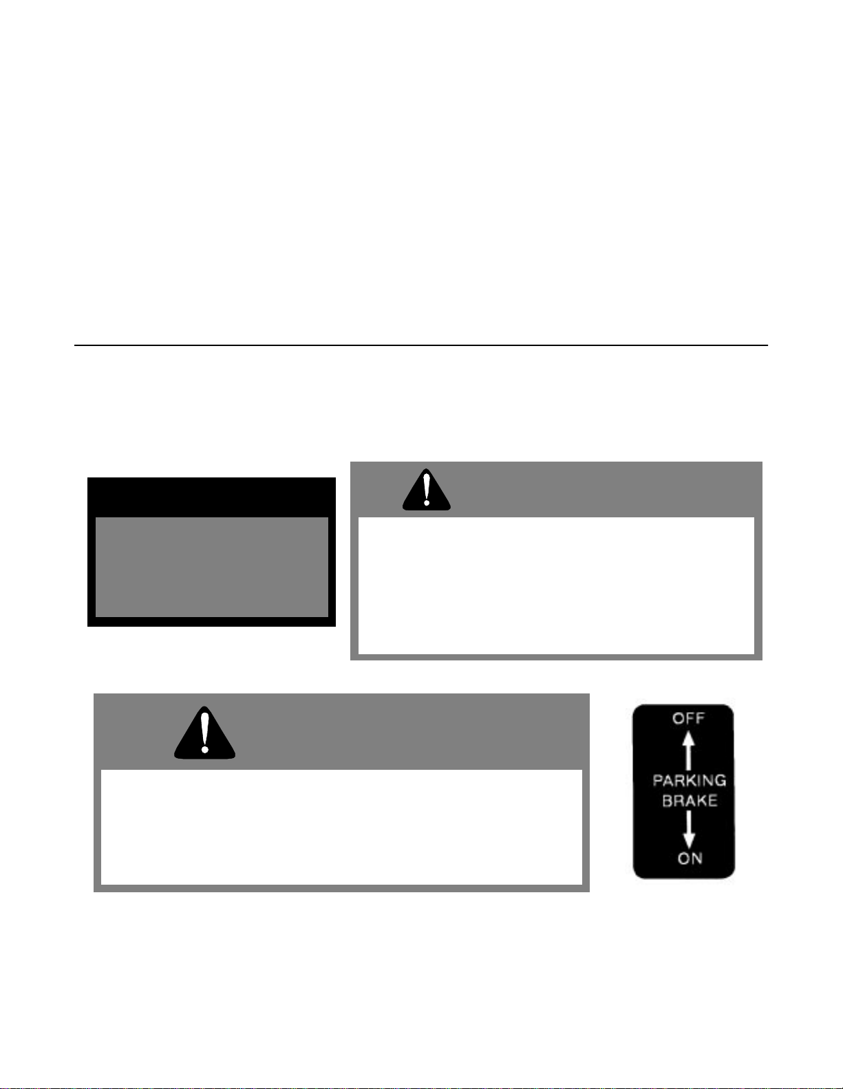
Parking
Brake Lever
A. CONTROLS
1. Ignition Switch:
the ignition circuit. If the neutral latch levers are in the neutral lock position, the ground speed control levers
are in neutral and the blade clutch is disengaged the engine can be started by pulling the recoil starter rope.
The engine can be shut off by turning the ignition key 45° counterclockwise.
2.
Fuel Shut off Va lve:
90 degrees. When t he hand le is in a horizontal position, it w ill s hu t off the flow of fuel to the engine. When it is
turned to a vertical position, it will open and allow fuel to flow to the engine. Anytime the mower is being
trailered or, if the mower will not be in use for 30 m inutes or more, close the fuel shutoff valve to prev ent
flooding the engine.
3. Engine Throttle:
lever from the front to the rear will increase the engine speed from slow to fast. To start the engine, set the
throttle all the way to the rear in the “Choke” position. After the engine starts, move the throttle halfway
between slow and fast. Always mow at full throttle.
4. Traction/Steering Levers:
a left-hand lever located beneath the outer end of the left handle. Each lever operates independently and
when squeezed against spring tension, freed from the neutral lock position (see Neutral Latch Levers below)
and released, permits the pump to send oil to the wheel drive motor at the rate set by the ground speed
control lever. When both traction/steering levers are released, the mower will move ahead in a straight line if
the engine is running and the ground speed control levers have been moved forward out of the neutral
position. Steering is accomplished by squeezing the traction/steering lever on the side to which the turn is to
be made. If both traction/steering levers are squeezed at the same time, the mower will stop and then backup.
The mower can then be steered in reverse by squeezing one of the traction/steering levers closer to the
handle than the other.
5. Ground Speed Control Levers:
maximum output of the two hydraulic pumps to the two wheel drive motors and thus the ground speed of the
mower independent of the engine speed. Moving the right lever forward increases the output of the right side
pump and moving the left lever forward increases the output of the left side pump. Normally these levers are
moved in unison. In order to start the engine both levers must be pulled back to the neutral position.
Located in the center of the control panel between the handles. A clockwise 45° turn closes
Located under the fuel tank in the ope ning of the handle m ount frame. The ha ndle turns
Located on the far right side of the control panel between the handles. Moving the throttle
Ground Speed
Control Levers
Ignition
Switch
Figure 1
There is a right-hand lever located beneath the outer end of the right handle and
Located on the right side of the control panel. These two levers control the
Electric Blade
Clutch
Operator Presence
Lever
Left Tracti o n
Steering Lever
Standard
Blade Clutch
8
Page 9

6. Neutral Latch Levers:
Pivoted inside each handle there is a neutral latch lever which works with each of the
traction/steering levers. When either of the traction/steering levers is squeezed and its neutral latch lever
pushed forward and engaged in the neutral lock position, the traction/steering lever is held in a position where
its pump should not be sending any oil to the wheel drive motor. (If this is not the case, see Initial Adjustments
6 and 7.) The neutral latch levers should be engaged in the neutral lock position before starting the engine.
The hardware for the neutral lock latches should be snug to maintain the latches in the “on” or “off” positions
when set by the operator.
The left traction /steering lever shown in the neut ral lock position.
7. Blade Clutch:
Located on the left handle just below the control panel. This is an over-center belt clutch and
when the handle is pushed forward until it snaps to rest, it forces the idler pulley into the blade drive belt
which causes the blades to rotate. When the handle is pulled back, the pressure on the belt is relieved and
the blades will stop rotating. Figure 1 show s the elect ric bla de clutch loca ted on the cont rol panel. This is an
on/off toggle switch that controls the electric blade clutch which supplies power to the cutting blades.
Figure 2
8. Operator Presence Levers:
Located above the outer ends of the right and left handles, these levers must be
held down on the handles against spring pressure when the engine is running in order to move the ground
speed selector levers out of neutral or engage the blade clutch. Releasing the operator presence levers with
the ground speed selector levers in any position other than neutral or the blade clutch engaged will shut off
the engine.
9. Freewheeling Valves:
A “T” valve located on the side of each hydraulic pump when opened will permit the
mower to be pushed forward or pulled in reverse without the engine running. To override the braking force of
the hydraulic system, turn each valve counterclockwise two turns, move the mower as you wish and then turn
each valve clockwise two turns to shut the valves.
Freewheeling
Valve
Pump
Figure 3
10.Hour Meter:
Located at the lower left edge of the control panel. The meter records total operating hours and
is running only when the engine is running. This hourmeter indicates hours when the engine is not running
and engine rpms when the engine is running. This unit also indicates lubrication intervals by flashing “LUBE”,
and it also indicates engine oil and filt er change interval s by fla shing “oil” . Bot h service r em inders will f lash
whether or not the engine is running.
9
Page 10

B. INITIAL ADJUSTMENTS
1. Disconnect the spark plug wire.
2. Check the tire pressure. Drive Wheels should be inflated to 25 psi. Caster Wheels should be inflated to 15 psi.
Note: New tires are overinflated in order to properly seat the bead to the rim.
3. Check that all nuts, bolts and screws are tight.
4. Check the tension of the deck drive belts:
a. Remove the deck cover shield and engage the blade clutch.
b. Make sure the belts clear the belt guides by 1/8" to 1/4".
c. T he t ension o f the de ck dri ve belts should be adju sted so that a ten-pound pull between two pu lleys
deflects each belt about 1/2".
with only moderate force.
d. Replace the deck cover shield and disengage the blade clutch.
5. The tension of the pump drive belt should be adjusted so that a five-pound pull between the engine traction
drive pulley and the pump drive pulley opposite the idler pulley deflects the belt about 3/16".
6. The long traction/steering control rods which run down to the pump control levers on each side of the handle
assembly should initially be adjusted so that when the ground speed control levers are in neutral and the
traction/steering levers are released from the neutral lock position, the mower stands still with the engine
running.
If the mower starts to creep forward or to the rear in this situation, then the turnbuckle at the top of the long
control rod on the side of the mower which seemed to creep must be adjusted.
Loosen the top and bottom nut on the turnbuckle and adjust until the drive wheel stops moving. Then
retighten the top nuts.
The short traction/steering control rods which run down from the traction/steering levers on eac h side of the
handle assembly should initially be adjusted so that when the ground speed control levers are in neutral and
the traction/steering levers are in the neutral lock position, the mower stands still with the engine running. If
the mower starts to creep forward or to the rear in this situation, then the rod end bearing at the bottom of the
short control rod on the si de of the mower which seemed to creep must be adjusted. Rem ove the hairpin
holding the long control ro d in place in the rod e nd bearing, remove th e flat washer and pull th e long control
rod from the rod end b earing. Loosen the lock nut and adju st the rod end bearin g ½ turn clockwise if the
creep was forward or ½ turn counterclockwise if the creep was to the rear. Tighten the lock nut, replace the
long control rod in the rod end bearing, replace the flat washer and the hairpin.
Do not overtighten these bel ts.
The blade clutch shoul d engage
7.
Adjusting the cutting height:
depending on the air pressure in the t ires. To change t he cutting height, blade spacers and/ or caster spacers
must be moved according to the table on page 12.
8. Lubricate all fittings listed in the maintenance section.
The mower is shipped with the cutting height set at 3 inches ±1/4 inch
10
Page 11

C. BREAK-IN AND OPERATION
1. Make certain you thoroughly understand all of the safety precaution s before you attempt to operate
this machine.
2. Check the engine oil level. Fill to the proper level with straight 30W eng ine oil rated for service SE or SF.
3. Check the hydraulic oil level. Remove the fill cap and make sure the hydraulic oil level is up to the bottom of
the strainer screen. Leave this a ir space for ex pan sion. If the hydraulic oil level is low, fill with a good grade of
SAE 20W50 engine oil.
4. Move the mower outdoors. Check the e ngine gasoline level. When filling the tank, s top when the gas oline
reaches one inch from the top. This space m ust be left for expans ion. Use fresh, clean, unleade d, regular
gasoline.
5. Move the mower to a “test area” where you can operate the mower for about half an hour without being
disturbed.
6. To start the engine:
a. Move the ground speed control levers back to the neutral position.
b. Disengage the blade clutch.
c. Place t he neut ral latch levers in the neutral lock position.
d. Connect the spark plug wire.
e. Open the fuel shutoff valve.
f. Move the throttle lever to the “Choke” position.
g. Put the key in the ignition switch and turn the switch to “ON”.
h. To start the engine, grasp the starter grip and pull slowly until the starter engages. The n pull the
cord rapidly to overcome compression, prevent kickback and start the engine. Repeat if necessary
with the choke opened slightly. When the engine starts, slowly open the choke all the way.
i. Set the throttle at 50% of full engine RPM and allow the engine to warm up. Then, adjust the throttle
to 75% of full engine RPM.
7. After the engine has warmed up, shut off the ignition switch and check the operation of the safety switches.
Make certain that the engine will not start unless the ground speed control levers are in neut ral and the blade
clutch is disengaged. If the engine will start with either of the ground speed control le vers in any position ot her
than neutral, immediately shut off the engine and replace the neutral safety switch operated by that lever
under the control panel. If the engin e will st art with the blade clu tch engaged, immedi ately shut off the engi ne
and adjust or replace, if ne cessary, the blad e s afety sw itch m ount ed on the engine deck. Start the engine and
hold the left operator presence lever do wn against the left handle and move the left ground s peed control
lever out of neutral. Now take your hand off the operator presence lever and the engine should die. If it does
not, immediately shut off the engine and adjust or replace, if necessary, the operator presence switch under
the control panel. Repeat this procedure moving the right ground speed control lever out of neutral. If the
engine does not die, immediately shut off the engine and adjust or replace, if necessary, the operator
presence switch under the control panel. Move both ground speed control levers into neutral, restart the
engine, hold the left operator presence control down agai nst the left han dle and en gage the blade clutch. Now
take your hand off of the o perator presence leve r and the engine s hould die. If it does not, immediately shut
off the engine and adjust or replace, if necessary, the operator presence switch under the control panel.
Disengage the blade clutch.
8. Restart the engine. Push the blade clutch lever forward until it engages and the cutter blades start rotating.
9. Move the ground speed control levers forward to about
one third of full speed.
CAUTION:
are fully familiar with the operation of the mower.
10. Squeeze both traction/steering levers with both hands and releas e the neutral latch levers from the neut ral
lock position.
“off”.
11. Slowly release the traction/steering levers and the mower will move ahead in a straight line. To turn the
mower, squeeze the traction/steering lever on the side to which you want to turn.
12. To stop the mower’s forward motion, squeeze both traction/s teering levers until the mower stops and place
Set the ground speed contro l levers at no more than one third full speed un til you
NOTE: The neutra l lat ch le ver h ard ware ne eds to b e s nug so th at the latc h s tays “o n” o r
11
Page 12

the neutral latch levers into the neutral lock position.
13.Before moving into reverse, the mower’s forward motion should be completely stopped.
14. P ractice operating the mower and as you ga in confidenc e, move the ground speed selector levers forward t o
two thirds full speed. Mow until comfortable and confident with the controls and then return the mower to the
shop.
WARNING:
transport only.
15.To stop and shut off the mower, squeez e both traction/steering l evers and place the neutral latch levers into
the neutral lock position, disengage the blade c lutch, move the ground speed co ntrol levers into neutral, turn
off the ignition to stop the engine, close the fuel shutoff valve and disconnect the spark plug wire.
16. Check, and adjust if necessary, the tension of the deck drive belts and the pump drive belt as described in
items 4 and 5 of the Initial Adjustment section.
17.Readjust the traction/ steering con trol rods. These adjustm ents are described in item 6 of the Initial Adjustment
section.
“OFF” positions.
18.After the first full day of mowing, all nuts, bolt and screws should be rechecked for proper tightness and the
belts should be rechecked for proper tension.
NOTE: Make sure the neutral latch hardware is snug so the latch will stay in the “ON” or
Do not mow at full speed. Set the ground speed control levers at full speed for
SECTION 7: CUTTING HEIGHT ADJUSTMENT TABLE
Note: The front edge of the cutting deck should be 1/8”-1/4” below the rear edge of the deck so that the blades are
cutting grass in only the front half of their circular path. This decreases friction and reduces the drive power
required.
Approximate
Cutting
Height
Inches Above Below Above Below
2
2-1/8
2-3/8
2-1/2
2-3/4
3
3-1/4
3-1/2
2-3/4
3
3-1/4
3-1/2
3-3/4
3-1/4
3-1/2
3-3/4
4
1/4” Blade Spacers
Above and Below the
Spindle Assemblies
0
1
2
1
2
3
4
5
0
1
2
3
4
0
1
2
3
5
4
3
4
3
2
1
0
5
4
3
2
1
5
4
3
2
1/2” Caster Spacers
Above and Below the
Caster Brackets
3
3
3
2
2
2
2
2
2
2
2
2
2
1
1
1
1
1
1
1
2
2
2
2
2
2
2
2
2
2
3
3
3
3
Engine Deck
Bolted to
Upper Holes
on Cutting
Deck
Engine Deck
Bolted to
Lowe r Hole s
on Cutting
Deck
12
Page 13

SECTION 8: MAINTENANCE
WARNING:
before perfo rm i ng any maintenan ce on t hi s m ower.
Disconnect the spark plug wire to prevent the engine from accidentally starting
A. GENERAL MAINTENANCE:
1. If the mower must be tipped on its side for maintenance, first drain the fuel from the fuel tank, the oil from the
engine’s crankcase and the hydraulic oil from the supply tank.
2. Be caref ul n ot to sp ill o il on any of the belts.
3. Do not tamper with the engine’s go vernor settings. They are adjusted to p rovide the p roper maxim um engine
speed.
4. If the mower is to be in storage for more than 30 days, drain the fuel tank, run the engine to drain the
carburetor dry, change the oil, remove the spark plug and pour a teaspoonful of oil into the cylinder. Run the
starter briefly to crank the engine and distribute the oil then replace the spark plug.
B. DAILY MAINTENANCE AFTER MOWING:
1. Park the mower outside the storage facility with the engine shut off.
2. Close the fuel shutoff valve.
3. Permit the mower to cool.
4. Disconnect the spark plug wire.
5. Wash the mower off with a water hose. Be sure to clean out grass clippings from under the cutter deck and
also under the deck cover. Allow the mower to dry before storing.
6. Check that the blade mounting bolts are tight.
7. Check that the blades are sharp. NOTE: Never mow with dull blades.
8. Check the fuel level, the engine oil level and clean the cooling-air intake (the rotating screen).
9. Clean the air cleaner elements (foam and paper).
10.After the first 5 hours of use, change the engine oil. (Change the oil every 100 hours thereafter.)
11.Follow the lubrication chart on the following page.
12.Place the mower in locked storage to avoid tampering or use by an untrained operator.
13. C heck condition and ope ration of all safety switches and make sure the neut ral latch hardware is snug so the
latch will stay in the “ON” or “OFF” positions.
C. MAINTENANCE EVERY 100 HOURS:
1. Change the engine oil and replace the oil filter. (Change the engine oil more frequently under severe
operating conditions.)
2. Change the hydraulic oil and the oil filter after the first 100 hours and every 500 hours thereafter.
3. Check that all nuts, bolts and screws are tight.
4. Check the condition and tension of all belts.
5. Clean the spark plug and check the spark plug gap.
6. Follow the lubrication chart on the following page.
13
Page 14

D. LUBRICATION CHART:
NUMBER OF
GREASIN G
POSITI ON S ITEM DESCRIPTI O N
Gear Deck Mowe
DAILY
EVERY
40
HOURS
r
2 A Cutter Blade Spindle Bearings
2
2
2
1
B
Caster Wheel Bearing
C
Cas ter W heel P ivot Shafts
D
Deck Idler Pulley Pivot Arms
Blade Clutch Bellcrank Pivot
Float Deck Mowe
r
Figure 4
E. ENGINE MAINTENANCE:
For detailed maintenance instructions for the engine on your m ower, see the E ngi ne M anual pack ed with your
mower .
F. HYDRAULIC SYSTEM MAINTENANCE:
The hydraulic system should not require maintenanc e other than the changing of the hydraulic oil and the oil
filter at 100 hours and every 500 hours thereafter. The pumps and wheel drive motors are not owner
repairable. If you have a problem with a pump or wheel drive motor, call your authorized Cub Cadet
Commercial Dealer for a replacement. Do not disassemble the pump or wheel drive motor.
14
Page 15

G. MOWER MAINTENANCE
1. TO CHANGE A BLADE:
a. Remove the deck cover.
b. Tip the mower back and block up the front of the deck.
c. Place on e wrench on the hex head bolt under the blade. Use a second wrench to remo ve the nut
on top of the spindle pulley.
d. Remember the number of blade spacers both above and below the spindle.
e. Remove the long (5/8" x 9 -1/2") blade bolt for f ixed decks and (3/4" x 7") blade bolt for float d ecks,
the flat washer, the blade and the blade spacers. (
bolt 90-115 ft.lbs.
)
See Figure 5.
Note: torque the 5/8"bolt 70-80 ft.lbs. and the 3/4"
Figure 5 48" Cutting Deck Shown
f. To replace the blade, reverse the above procedure. Be careful to replace the blade spacers
correctly above and below the spindle.
2. TO CHANGE THE BLADE DRIVE BELTS:
a. Make sure the blade clutch is disengaged.
b. Remove the deck cover.
c. Rem ove the nut and the cap screw which serves as a belt guide and is mounted in the idler pulley
arm. See Figure 6.
Figure 6
15
Page 16

d. Loosen the two belt guides under the engine deck and rotate them out of the way.
Figure 7
e. Slip the long blade drive belt off of the pulleys.
f. Loosen the idler pull rod which holds the idler pulley tight against the short blade drive belt. See
Figure 7.
g. Remove the short blade drive belt from the pulleys.
h. Place a new short blade drive belt back on the pulleys and tighten the idler pull rod to hold the idler
pulley tight against the belt.
i. P lace a new long blade drive belt through the belt guide and lo op it around the engine pulley and
then around the two deck pulleys. The belt’s back side should ride on the idler pulley.
j. Rep lace the cap screw and nut in the idler pulley arm. Readju st and tighten the two belt guides
under the engine deck.
k. T he idler pulleys shoul d be adjusted so t hat when the blade clu tch is engaged, a ten-pound pul l
between two pulleys d eflec ts either be lt about 1/2". Do not o vertigh ten the se belts. The blade clutch
should engage with only moderate force.
l. Rep lace the deck co ver.
16
Page 17

3. INSTALLATION AND REMOVAL OF MOWER FLOAT DECK
1. Power Unit Frame Tube
2. Stop Tabs
3. Mower Deck Channel
4. Retaining Pin
5. U-Bracket
PREPARATION
Place the mower deck in front of the power unit on a level surface. Turn off power take-off (PTO), turn off engine
and remove key from ignition switch.
CAUTION:
WARNING:
injury.
WARNING:
1. Turn the T Handles located on each side of the hydraulic pumps counter clockwise two turns to move unit
without engine running.
2. Remove center mower deck cover by first removing two large wing nuts.
3. With the mower deck positioned in front of the power unit,
frame tubes.
Push down on power unit handle bar to bring the front caster wheels to a level above top of the mower deck.
4.
Push the power unit over the mower deck. Align the power unit frame tubes with the mower deck channels.
5.
6. Slowly reduce force on the handle bar to lower the front caster wheels until they rest on the surface with the
frame tubes inside the mower deck channels.
7. Push the power unit forward until the rear stop tabs of the frame contact the mower deck channels.
The mower deck and power unit must be placed on a hard, level surface.
Disengage the PTO, stop engine and remove key to avoid accidental starting and
When handling the mower deck, be careful not to cut yourself on the sharp blades.
visually align
mower deck channels with power unit
INSTALLING THE MOWER DECK
17
Page 18

WARNING:
injury.
Disengage PTO, stop engine and remove key to avoid accidental starting and
WARNING:
Lift one side of the mower deck to achieve the desired cutting height.
1.
2. Push the button in the center of the handle of eac h of the retainin g pins to insert the ret aining pins th rough t he
appropriate front and rear height adjustment holes in the mower deck channel. Select the lowest holes that
allow insertion of the pins just abov e the bottom inside edge of the power unit frame U-brackets inside the
brackets.
NOTE:
3.
4. Repeat the above procedure to install the other side of the mower deck.
NOTE:
5.
6. Install the PTO belt by executing the following procedures:
NOTE:
The same height adjustment hole must be used for both front and rear pin installation.
Release the mower deck.
The same height adjustment hole must be used for all four pin installations.
Adjust the mower deck as required. Refer to “Adjustments” in your Operator’s Manual.
1. Remove center mower deck cover by first removing two large wing nuts.
2. Push against idler arm to release tension on the PTO belt. For increased lev erage, a 3/8-inch square
drive of a breaker bar can be placed in the 3/8-inch square hole of the idler arm. The breaker bar handle can be pushed to release tension on the PTO belt.
Be sure the na rrow side of the belt is in the bott om of t he pulley groov es .
3. Carefully remove old PTO belt, and replace it with a new belt.
4. Release force on the idler ar m to restore tension to new PTO belt. If used, remove breaker bar from
idler arm.
5. Replace center mower deck cover and secure it in place with two large wing nuts.
When handling the mower deck, be careful not to cut yourself on the sharp blades.
NOTE:
7. Turn the T Handles on each side of the hydrau lic pumps clockwise two turns to shut the valves. (CAUTION
Ensure that the center mower deck cover is replace d and secured with the two large wing nuts.
DO NOT OVERTIGHTEN.
18
Page 19

REMOVING THE MOWER DECK
WARNING:
injury.
WARNING:
blades.
1. Remove the center mower deck cover by first removing the two large wing nuts.
2. Remove the PTO belt.
3. Lift one side of the mower deck.
4. Push the button in the center of the handle of eac h of t he tw o retai ning pins supporting this side of the m ower
deck. Remove the pins.
5. Lower this side of the mower deck until the ball wheels rest on the surface.
6. Repeat steps 3 through 5 for the other side of the mower deck.
7. Turn the T handles located on the side of each hydraulic pump count erclockwise two turns to move the unit
without engine running.
8. Push down on the power unit handle bar to bring the front caster wheels to a level above the top of the mower
deck.
9. Pull the power unit backwards, free of the mower deck. Slowly reduce force on the handle bar to lower the
front caster wheels until they rest on the surface.
Disengage PTO, stop engine and remove key to avoid accidental starting and
When handling the mower deck cover, be careful not to cut yourself on the sharp
19
Page 20

TO CHANGE THE PUMP DRIVE BELT:
4.
a. Make sure the blade clutch is disengaged.
b. Working under the engine deck, take the long blade drive belt off of the engine pulley.
c. Lo osen the locknut holding the pu mp drive belt idler pulley in place and slide the pulley aw ay from
the pump drive belt.
d. Remove the old belt and mount a new belt on the pulleys.
e. Slide the idler pulley back onto the belt and tighten the locknut holding it in place. The idler pulley
should be ad justed so that a five-poun d pull on the belt be tween the engine pul ley and the pump
pulleys deflects the belt about 3/16".
f. Replace the long blade drive belt on the engine pulley.
See Figure 8.
Figure 8
5. TO CHANGE A SPINDLE ASSEMBLY
a. Make sure the blade clutch is disengaged.
b. Remove the deck cover or covers.
c. Rem ove the blade.
d. Remove the blade drive belts.
e. Remove the two bolts which hold the pulley bushing tight in the spindle pulley and thread the bolts
into the other two holes in the bushing. (For float deck mowers, skip to “i” ).
f. Alternately turn each bolt 1/2 turn clockwise until the bolts force the pulley off of the bushing.
g. Remove the bushing by tapping a large screw driver into the slot in the side of the bushing.
h. Remove the key from the spindle.
i. Tip the mower back and block up the front of the deck.
j. Remove the bolts and locknuts (four for fixed and three for float decks) holding the spindle
assembly to the deck.
k. Remove the spindle assembly.
20
Page 21

6. TO CHANGE SPINDLE BEARINGS (Fixed Decks Only):
(See the exploded view drawing on page 19.)
a. Clamp the spindle assembly in a vise with the grease fitting pointing up.
b. Bend down the tab of the tab lockwasher.
c. Rem ove the hex jam nut.
d. Obtain a round wooden dowel about 6-inches long such as a piece of broom handle. Hold this
wooden dowel on top of the spindle and tap it with a hammer to drive the spindle out of the
bearings and the spindle housing.
e. Pull the seal spacer out of the top seal.
f. Using a large screwdriver, pry the seals out of each end of t he spindle housing. (NOTE: You will
destroy the old seals as you remove them.) As you remove the old seals, the inner races of the
roller bearings and the internal spacer will fall out of the spindle housing.
g. Using a bearing puller, remove the outer races from both ends of the bearing housing.
NOTE: If the outer races cannot be removed using this procedure, take the sp indle housing to a local machine
shop and let them remove the bearing races.
h. Clean the old grease out of the spindle housing.
i. Cl amp the housing in a vise with the grease fitting pointing down.
j. G ent ly drive a new bearing outer race back i nto the s pindl e hou sing us i ng the wooden dowel. Make
certain that the tapered side of the race faces outward.
k. Pac k one inner race with fresh grease and place it into the outer race.
l. P ress one of th e new seals into the spindle housing by using the wooden dowel, moving around the
circumference of the seal and tapping gently with a hammer.
NOTE: The metal surface of the seal should face outward.
m. Turn the housing over and re-clamp it in the vise with the grease fitting pointing up.
n. Gently drive the second bearing outer race back into the spindle hous ing using the wooden dowel.
Make certain that the tapered side of the race faces outward.
o. Insert the internal spacer.
p. Pack the second inner race with fresh grease and place it into the outer race.
q. Press the second ne w seal i nto the sp indle hous ing by using the wooden dowel, moving around t he
circumference of the seal and tapping gen tly with a hammer. NOTE: The metal surface of the seal
should face outward.
r. Coat the spindle with grease and push it up through the bottom of the spind le housing. The spindl e
will pass through the lower seal, an inner race, the internal spacer, an inner race and the upper
seal.
s. Hol d the spindle in place and install the seal spacer down over the spindle and push it into the top
seal. There is a notch on one of the inside edges of the seal spacer that s hould be facing up and
should be oppos ite the side of the spi ndle with the ke yway. Install the new tab lockwasher with its
bent inner tab pointing down to engage with the notch in the seal spacer. Install the hex jam nut and
torque it to 100 ft. lbs. Bend up the large tab on the tab lockwasher to hold the jam nut in place.
21
Page 22

SECTION 9: REPLACEMENT PARTS
SPINDLE - Part No. 00057412 (Fixed Decks)
Ref. Description Qty.
1Hex Jam Nut 1
2 Tab Lockwasher 1
3 Seal Spacer 1
4 Top and Bottom Seal 2
5Bearing 2
6 Spindle Housing 1
7 Internal Spacer 1
8 Cutter Blade Spindle 1
9 Grease Fitting 1
SPINDLE REPAIR KIT NO. 00054433
Ref. Description Qty.
2 Tab Lockwasher 1
4 Top and Bottom Seal 2
5Bearing 2
Spindle, 48"/54" Float Deck
Spindle, 60" Float Deck
SUGGESTED MOWER REPLACEMENT PARTS
Part No. Description Qty. Part No. D escription Qty.
00021871 Rotary Blade, 16-1/2" Fixed 2 or 3 00021947 Drive Belt, Long, 48" Fixed 1
01001367 Rotary Blade, 16-1/2" 2 or 3 00050441 Drive Belt, 36" 1
-- -- -- -- -- --
01001490 Rotary Blade, 18.5" 2 or 3 00050480 Drive Belt, Short, 48" Fixed 1
-- -- -- -- -- -00013091 Blade Bolt 5/8" 2 or 3 0100171 0 V Belt, Drive, 48"/54" 1
01000373 3/4"-16, Hex Cap Screw, 6.0 2 -- -- -01002074 3/4"-16, Hex Cap Screw, 7.75 1 01000399 Spindle Drive Belt 48" Float 1
00011807 BladeNut 5/8" 2 or 3 0100475 2 V Belt, Spindle, 54" 1
01000380 3/4"-16, Hex 3 01007333 Pump Drive Belt, All 1
00021924 Blade Spacer 5/8" 10 00018969 Cartridge, Hydraulic Oil Filter 1
01002564 Spacer .76 ID x 2.00 OD x .477 3
SUGGESTED ENGINE REPLACEMENT PARTS
Engine Oil Filter Air Fil ter Air Filter Foam
Wrap
00035048 Kawasaki, 15. 0 HP KM-49065-2078 KM-1 1013-2141 KM-11013- 2109 KM-BPR5ES
01000998 Kawasaki, 17 HP KM-49065-20 78 KM-11013-7002 KM-11013-7001 759-3331
01003613 Kawasaki, 19 HP KM-49065-2078 KM-11013-7010 KM-110 13-7009 KM-BPR5ES
Spark Plug
Page 23

MAINTENANCE RECORD
DATE WORK PERFORMED DATE WORK PERFORMED
23
Page 24

MANUFA C TURER’S LIMITED WARRANTY - TURF EQUIPMENT
This warranty is specific to the product ma nua l to wh ich it is attac hed.
For a complete list of products and warranties contact y our aut hori zed Cub Cadet Comme rcial dealer.
Proper maintenance of the purchased Cub Cadet Commercial equipment is the owner’s responsibility.
Follow the
instructions in your owner’s manual for correct lubricants and maintenance schedule. Your Cub Cadet Commercial dealer
carri es a comp lete li ne of qua lity lu bricants and fi lters for your equi pment’s engi ne, transmi ssion, c hassis, a nd atta chments.
What is C over ed By Thi s Warra nty ?
This l imit ed warra nty c overs any de fect in ma ter ia ls and /or wor kma nshi p in you r
Cub Cadet Commer cial equipment to the original owner for the following time periods:
A) First (1
associated
Labor
B) Second (2
st
) Year of Original Ownership:
of the particular repair are covered under the terms of this limited warranty
nd
) and Third (3rd) Year of Original Ownership:
Bot h Part s
found defective in materials and /or workmanship
Parts
found defective in materials and /or workmanshi p are
and
the
covered under the terms of this limited warranty.
•
Limited Battery Warranty
workmanship, thereafter prorated for the period from the fourth (4th) through the twelfth (12
•
“No-Fault Warranty”: Covers th e “No- Fault” t o owne r repl acem ent o f dam aged belt s, tire s, sea ts, an d grass
: 90-day free battery replacement in the case of defects in materials and/or
th
) mont h of ownership.
bags (cutting blades are not include d) for a period of One (1) month or One-Hundred (100) hours, whichever comes firs t.
•
Limit ed Engi ne Warranty
: Parts and Labor for defects in materials and/or workmanship are covered for the
first two (2) years of original equipment ownership. Refer to the Engine Manual for spec ific limitations and restrictions.
Accordingly, Cub Cadet Commercial will replace or repair any part or parts without charge through your authorized Cub
Cadet Com mercial dea ler subjec t to the above ti me and coverage l imitation s. U pon completi on of your purc hase, the
Serial Number/s of the unit will be registered with the Cub Cadet. This will initiate and validate your limited warranty and
the applicable Warranty Period.
What is Not Covered By this Warranty?
Cub Cad et Commercial does not warrant ( a ) routine maintenance items such
as lubricants, filters (oil, fuel, air and hydraulic), cleaning, tune-ups, brake or clutch inspections, adjustments made as part
of normal maintenance, blades, blade sharpening, equipment setup, and normal wear items; ( b ) incidental cost such as
transporting equipment to and from the dealer, telephone charges or renting product temporarily to replace a warranted
product; ( c ) damage caused by use of the equipment for pur poses other than those for which it was designed; ( d )
damage caused by accident o r Disas ters such as fire, f lood, wind and lighting: ( e ) da mage cau sed by unau thorized
attachments, modifications, alterations, improper servicing or maintenance, improper storage; or ( f ) any other abuse or
misus e of the equipment.
Exclusiv e Warr ant y.
The foregoing warranty is exclusive and in lieu of all other warranties or remedies, whether written,
oral or implied. Any and all implied warranties of merchantability, fitness for particular purpose, course of delaying or
usage o f t rad e are he reby exp re ss ly di sc la im ed an d exclu de d
. (Some states do not allow the exclusion or limitation
of incidental or consequential damages, so the above exclusion or limitation may not apply to you.)
Limitation of Remedies.
Under no circumstances, except to the extent such exclusions are prohibited by applicable law,
shall Cu b Cadet Commercial be li able for any loss or da mage, direct or indirect , special, incidental or conseq uential
arising out of the use of or inability to use this equipment including but not limited to any claim for loss of profits, loss of
profits, loss of savings or revenue, loss of use of the equi pment or any associated equi pment, facilities or continued
service, downtime, the claims of costs of third parties including customers and injury to property. Some states do not
allow limitations on how long an implied warranty lasts of the exclusion or limitation of incidental or consequential
damages, so the above limitations or exclusion may not apply to you.
This warranty give s you specific leg al rights , and
you may also have other rights that vary from state to state.
Futu r e C ha nges
: Cub Cadet Commercial reserves the right to reserve, chang e or mod ify the construction and design o f
its equipment or any component part or parts thereof without incurring the obligations to make such changes or modifications in present equipment.
How to Obta i n Se rvice:
Contac t t he au tho r i zed Cub Ca de t Com m erc ia l de al er a t t he poi nt o f or i gi na l ret ai l pu rch ase t o
obtain service or replacement parts.
Products purchased outside the USA are not covered by this warran ty
Cub Cadet LLC
P.O. Box 361131
Cleveland, Ohio 44136
Form No. 01006627 Rev. 02-1 11/13/2002
 Loading...