

CSZ LT 749 User manual

MICRO-TEMP LT
Operation and Technical Manual
Model 749 Localized Therapy Units
Cincinnati Sub-Zero Products, Inc. • 12011 Mosteller Road • Cincinnati, Ohio 45241, U.S.A.
www.cszmedical.com
In Europe: • CEpartner4U • Esdoornlaan 13, 3951 DB Maarn.
The Netherlands
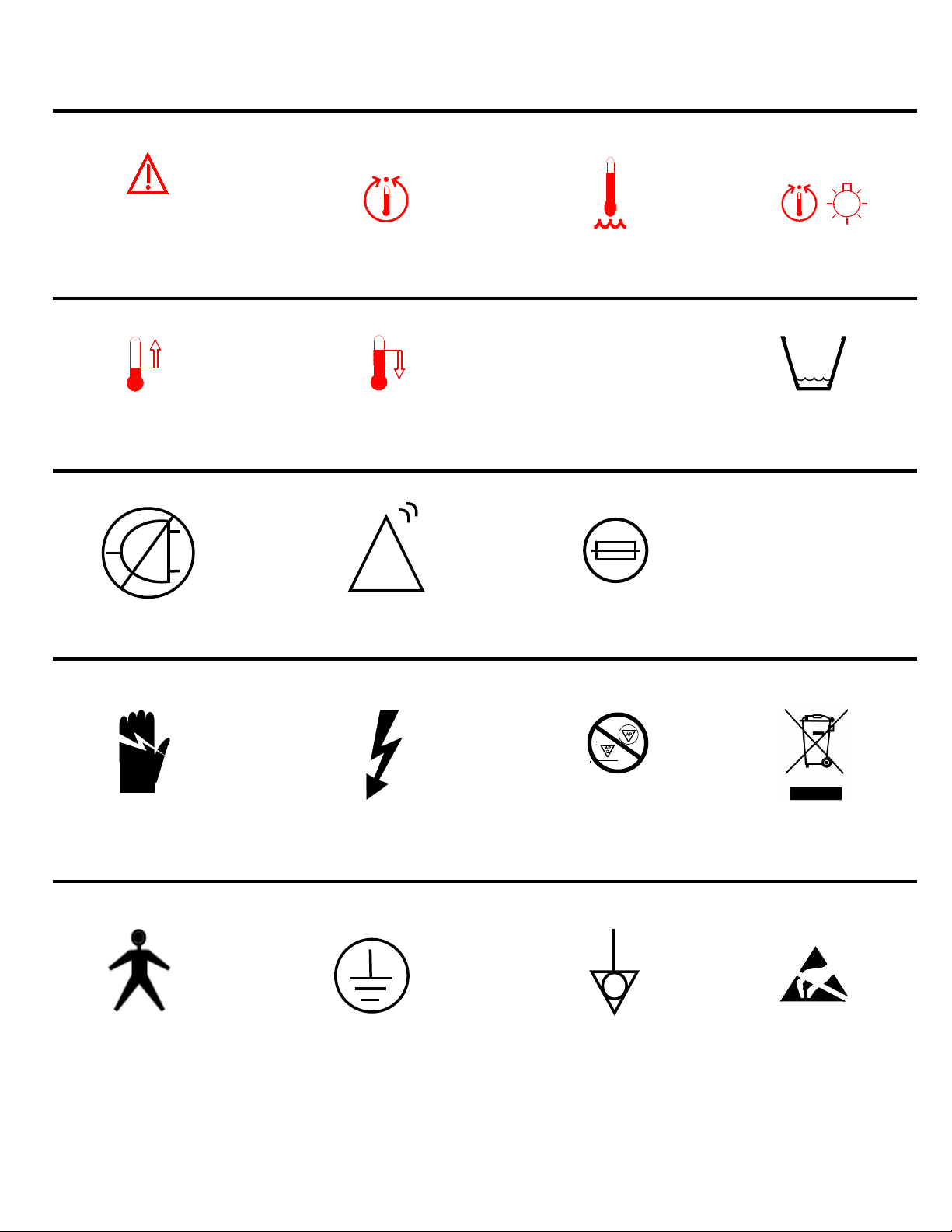
MICRO-TEMP LT
Temperature
Point Indicator
O / I
Attention: Read
Operation Instructions
and Manual Before
Operating
Temperature Set
Symbols / Definitions
Water
Temperature Set
Increasing
Temperature
Power Failure
Disconnect Power
Before Servicing
Decreasing
Temperature
CAUTION
Danger; Risk of
Electric Shock
OFF / ON Switch
Fuse
Risk of Explosion:
Do not use in the
Presence of Flammable
Anesthetics
Low Water
Level
AC Voltage
Separate collection for
electrical and electronic
equipment
Type B
Equipment
Earth (Ground)
Equipotentiality
II
ESD
Susceptibility

MICRO-TEMP LT
OPERATION AND TECHNICAL MANUAL
Cincinnati Sub-Zero Products, Inc., reserves the right to make equipment changes and improvements, which
may not be reflected in this manual.
WARNING
• Read Operation Manual before operating.
• A physician's order is required for setting pad temperature and use of equipment. As
directed by physician, check patient's temperature and skin condition of areas in contact
with pad. Check the pad water temperature. Pediatric patients, temperature-sensitive
patients with vascular disease, surgical patients, diabetics, and Raynauds disease patients
should be checked more frequently. Notify the physician promptly of any change in
patient status in order to avoid serious injury or death. Failure to inform the
physician of any deviation may result in injury to the patient.
Pediatrics – Infants and children’s body temperature are more responsive to
surface heating than adults. Due to their size, the effect of heating a child is more
pronounced because of their higher ratio of skin contact area to body mass.
Temperature Sensitive Patients – Patients with impaired peripheral blood
circulation and patients who are incapacitated may be more sensitive to
temperature changes than patients with normal circulation.
Surgical Patients – Patients with poor circulation due to inadequate heart function,
loss of blood, or impaired peripheral blood circulation may be more sensitive to
temperature changes.
• If device is used at home, patient must follow directions prescribed by their
physician and be aware of all warnings and cautions mentioned throughout the manual.
• Observe patient’s skin condition frequently due to individual differences in
sensitivity and susceptibility to injury from heat and/or externally applied chemicals
or pressure. Patients at greatest risk are those unconscious, on prolonged therapy,
diabetics, children, and persons incapacitated, with sensitive skin areas, or poor
circulation.
• Do not use for ECMO (Extracorporeal Membrane Oxygenation) therapy.
• Heating may affect toxicity of certain prep solutions which has been reported to
cause skin injury when remaining on patient’s skin during application of prolonged
heat. For moist heat therapy, moisten the pad using distilled water only.
• The method of temperature control provided by all localized heat therapy units presents the
danger of heating body tissues, particularly the skin, to a point where they are injured, i.e.,
burns. Depending on the extent and severity of a burn, very serious complications may
arise.
• Prevent excessive and/or prolonged tissue pressure and shearing forces, especially over
bony prominences, to prevent skin damage that may result.
• Do not wrap pad so tightly as to constrict blood flow. Do not use pins to secure pad
or hoses. Do not allow pad or hoses to come in contact with any sharp object.
• Do not place additional heat sources between the patient and pad. Skin damage may
result.
Manual 57203 Rev. I
DCN: M006-3983
III

WARNING
• Proper sanitation procedures must be practiced and hygienic safety must be
maintained, to prevent contamination. Contamination can affect patient’s health, i.e. skin
irritation/rash may result.
• Any time water is found leaking into or around the unit, connecting hose, and/or pad, turn
the unit off, disconnect the power cord from its power source, and correct the problem
before proceeding. Water leaks could lead to electric shock.
• Water leaks present a risk of infection and should be handled accordingly. Proper
sanitation procedures should be followed including, but not limited to, the preventative
maintenance described in this manual. Leaky pads or hoses, as well as unapproved
pads should never be used.
• Do not use the MICRO-TEMP LT system in the presence of flammable anesthetics. Risk of
explosion can result.
• For continued protection against risk of fire, replace only with same type and rating of
fuse.
• This device is still energized when the inlet switch is in the off position. To completely
disconnect the device from the power source, remove the appliance plug from the back of
the unit.
• Always unplug the unit before accessing internal components during service. Failure to
unplug the unit could result in electric shock.
• Do not by-pass ground on power cord plug. Electrical Hazards may result.
• Do not position unit near any objects that can generate a strong electrical/magnetic field.
Potential electromagnetic interference may result. If interference is observed, re-locate
the unit away from such devices.
• The display may blank momentarily during an electrostatic discharge event, but the
essential performance of the unit is not affected and no harm will occur to the patient. If an
electrostatic discharge event occurs, check to see if unit is operating properly. If unit does
not return to previous operation, turn unit off then back on and reset temperature settings
as prescribed.
• Keep air vents free of debris and obstruction. Blockage of vents could result in the unit
overheating which could render the unit unable to provide adequate therapy and
excessive surface temperatures could cause injury of patient or operator. Keep unit,
specifically the air vents, away from curtains or other obstructions.
• Remove the MICRO-TEMP LT from service if the outer casing or membrane control panel is
cracked or internal components are exposed. Contact with internal components could
result in electric shock or thermal injury to the patient or operator and exposure to
sharp edges.
• Before returning the MICRO-TEMP LT to patient use after repairs, the MAINTENANCE
CHECKLIST in Section 4 must always be performed. Improper repair and inadequate
maintenance can result in system damage and patient injury.
• The repair, calibration, and servicing of the MICRO-TEMP LT should be performed by
qualified Medical Equipment Service Technicians, Certified Biomedical Electronics
Technicians, or Certified Clinical Engineers familiar with good repair practices for servicing
medical devices, and in accordance with instructions contained in this manual. Improper
repair can result in system damage and patient injury.
IV

CAUTION
• Always drain the MICRO-TEMP LT to a sanitary drain because bio-contaminants may
be present in the unit’s water supply.
• Do NOT fill the reservoir to the bottom of the strainer if there is water in the pad.
This could cause an overflow when the unit is turned on.
• Working with electronic boards, plugs, and cables requires delicate handling. Proper
Electrostatic Discharge procedure should be followed during replacement of any
electronic board.
• Use only CSZ provided hospital grade power cord assembly and used in
conjunction with a properly grounded receptacle or electric shock may result.
• Do not operate pump without a pad connected or with pad clamps in the “CLOSED”
position. Always check clamps to make sure they are fully open.
• Full or partial covering of pads with materials with high insulative properties (pillows, etc.)
could cause excessive retention of heat in the patient leading to injury.
• The pad surface should be checked for freedom from mechanical damage prior to each
application.
• Complete folding of pad may restrict flow and reduce therapy to patient.
• Make sure hose and pads are free of kinks that might restrict flow.
• Check hose couplings to be certain they are properly locked together.
• Follow pad instructions and Hospital/Physician instructions for applying, storing, and
disposal of product.
• Do not use alcohol. Alcohol may cause pad and unit deterioration.
• Use distilled water only. Do Not Use De-Ionized water or tap water. Failure to use
distilled water may result in poor performance and damage to the Micro-Temp LT.
• It is recommended that two (2) ounces of Propylene Glycol be added to the reservoir
upon fill up.
MICRO-TEMP LT, MAXI-THERM®, MAXI-THERM LITE®, and TEMP-PAD® are registered
trademarks of Cincinnati Sub Zero Products, Inc., Cincinnati, Ohio USA.
©
Copyright 1982, Cincinnati Sub-Zero Products, Inc. All rights reserved.
V

TABLE OF CONTENTS
TECHNICAL HELP ...................................................................................................................................................1
AUTHORIZED EUROPEAN REPRESENTATIVE: ..............................................................................................1
BEFORE YOU CALL FOR SERVICE..........................................................................................................................1
IN-WARRANTY REPAIR AND PARTS .....................................................................................................................1
RECEIVING INSPECTION.......................................................................................................................................1
IMPORTANT SAFETY INFORMATION...............................................................................................................1
SECTION 1. INTRODUCTION................................................................................................................................2
1-0.
GENERAL SAFETY PRECAUTIONS ..........................................................................................................2
1-1.
GENERAL DESCRIPTION OF THIS MANUAL..........................................................................................2
1-2.
GENERAL DESCRIPTION OF THE MICRO-TEMP LT SYSTEM .............................................................2
1-3.
CLINICAL APPLICATIONS .........................................................................................................................3
1-4.
PHYSICAL DESCRIPTION OF THE MICRO-TEMP LT UNIT...................................................................3
1-4.1. EXTERNAL FEATURES - FRONT VIEW .......................................................................................3
1-4.2. EXTERNAL FEATURES - REAR VIEW .........................................................................................5
1-4.3. EXTERNAL FEATURES – MEMBRANE CONTROL PANEL....................................................7
1-5. REQUIRED ACCESSORIES................................................................................................................................9
1-6.
FUNCTIONAL DESCRIPTION OF THE MICRO-TEMP LT SYSTEM.......................................................9
1-6.1. THEORY OF OPERATION...............................................................................................................9
1-6.2. HEATING SYSTEM..........................................................................................................................9
1-6.3. CIRCULATING SYSTEM.................................................................................................................9
1-6.4. TEMPERATURE SAFETY CONTROL SYSTEM .........................................................................10
SECTION 2. GENERAL PREPARATION OF THE MICRO-TEMP LT SYSTEM ........................................11
2-1.
INTRODUCTION.........................................................................................................................................11
2-2.
UNPACKING THE SHIPMENT ..................................................................................................................11
2-3.
FIRST TIME SET-UP/SYSTEM TEST ROUTINE......................................................................................11
2-3.1. INSPECTING AND ARRANGING THE EQUIPMENT ................................................................11
2-3.2. COMPLETING A SYSTEM TEST ROUTINE ...............................................................................12
2-5.
PATIENT PREPARATION AND BEDSIDE CARE....................................................................................14
SECTION 3. OPERATING THE MICRO-TEMP LT UNIT...............................................................................17
3-1.
INTRODUCTION.........................................................................................................................................17
3-2.
ARRANGING THE SYSTEM COMPONENTS ..........................................................................................17
3-3.
OPERATING THE MICRO-TEMP LT ........................................................................................................19
3-4.
CONCLUDING LOCALIZED HEAT THERAPY TREATMENT ..............................................................20
3-5.
STATUS DISPLAY AND ALARM MESSAGES ........................................................................................20
SECTION 4. GENERAL MAINTENANCE OF THE MICRO-TEMP LT SYSTEM.......................................23
4-1.
INTRODUCTION.........................................................................................................................................23
4-1.1.
TEST EQUIPMENT REQUIRED.............................................................................................23
4-2.
MAINTENANCE OF THE WATER RESERVOIR......................................................................................25
4-2.1. DRAINING THE RESERVOIR.......................................................................................................25
4-2.2. REPLENISHING THE RESERVOIR ..............................................................................................25
4-2.3. DISINFECTION/DRY STORAGE PROCEDURE FOR CIRCULATING WATER UNITS........26
4-3.
MAINTENANCE OF THE MICRO-TEMP LT EXTERIOR – CLEANING INSTRUCTIONS ..................28
4-4.
DISPOSAL OF THE LOCALIZED HEAT THERAPY PADS.....................................................................28
4-5.
CURRENT LEAKAGE TEST ......................................................................................................................28
4-6.
GROUND CONTINUITY TEST..................................................................................................................29
4-7.
FLOW RATE TEST......................................................................................................................................29
4-8.
>1°C (2°F) OVER SET POINT CHECK.......................................................................................................30
4-9.
TEMPERATURE ACCURACY CHECK.....................................................................................................30
4-10. HIGH LIMIT SAFETY CHECK...................................................................................................................31
4-11. LOW WATER ALARM CHECK..................................................................................................................31
4-12. POWER FAILURE ALARM CHECK..........................................................................................................32
4-13. TILT SWITCH ALARM CHECK.................................................................................................................33
VI

SECTION 5. FIELD REPAIR/SERVICE OF THE MICRO-TEMP LT UNIT .................................................34
5-1.
INTRODUCTION.........................................................................................................................................34
5-2.
ACCESS TO THE INTERIOR OF THE MICRO-TEMP LT UNIT ...................................................................36
5-2.1. SEPARATING THE FRONT AND REAR ENCLOSURES............................................................36
5-2.2. RECONNECTING THE FRONT AND REAR ENCLOSURES .....................................................36
5-2.3. DISCONNECTING THE CABLES FROM THE CONTROL BOARD..........................................37
5-2.4. DISCONNECTING THE CABLES FROM THE DISPLAY BOARD............................................37
5-3.
REPLACEMENT OF THE HEATER.................................................................................................................38
5-4.
REPLACEMENT OF THE PUMP .....................................................................................................................39
5-5.
REPLACEMENT OF THE RESERVOIR ..........................................................................................................40
5-6.
REPLACEMENT OF THE TWIN BLACK TUBING........................................................................................41
5-7.
REPLACEMENT OF THE WATER TEMPERATURE SENSOR (THERMISTOR)........................................41
5-8.
REPLACEMENT OF THE I/O POWER SWITCH ............................................................................................43
5-9.
REPLACEMENT OF FUSES IN THE I/O POWER SWITCH.....................................................................44
5-10.
REPLACEMENT OF THE WATER LEVEL SENSOR ASSEMBLY.............................................................45
5-11.
REPLACEMENT OF THE CONTROL BOARD AND/OR DISPLAY BOARD AND/OR THE
MEMBRANE CONTROL PANEL.............................................................................................................................45
5-12. TROUBLESHOOTING GUIDE...................................................................................................................48
SECTION 6. PARTS INFORMATION..................................................................................................................53
6-1. INTRODUCTION ...............................................................................................................................................53
6-2.
ORDERING INFORMATION FOR REPLACEMENT PARTS........................................................................53
6-3.
RECOMMENDED REPLACEMENT PARTS INVENTORY...........................................................................53
6-4.
RETURNING PARTS UNDER WARRANTY..................................................................................................54
6-5.
SHIPPING PARTS .............................................................................................................................................54
SECTION 7. SPECIFICATIONS AND CERTIFICATIONS OF THE MICRO-TEMP LT.............................61
TABLE OF FIGURES
Figure 1-1. Micro-Temp LT Unit - Front View....................................................................................................... 4
Figure 1-2. Micro-Temp LT - Rear View.................................................................................................................6
Figure 1-3. Micro-Temp LT – Membrane Control Panel (100/115V)..................................................................8
Figure 1-4. Micro-Temp LT – Membrane Control Panel (230/240V)..................................................................8
Figure 4-1. Maintenance Checklist..........................................................................................................................24
Figure 5-1. Micro-Temp LT Unit - Exposed Rear View.......................................................................................35
Figure 6-1. Micro-Temp LT Unit - Internal Exploded - Front View..................................................................55
Figure 6-2. Parts List A.............................................................................................................................................55
Figure 6-3. Micro-Temp LT - Internal Exploded Rear View...............................................................................56
Figure 6-4. Parts List B.............................................................................................................................................56
Figure 6-5. Micro-Temp LT Unit – Reservoir - Side View...................................................................................57
Figure 6-6. Parts List C.............................................................................................................................................57
Figure 6-7.A Electrical Wiring Diagrams – 100V & 115V......................................................................................58
Figure 6-7.B Electrical Wiring Diagram – 230/240V...............................................................................................59
Figure 6-8. Micro-Temp LT Accessories ..........................................................................................................60
Table 7-1. Guidance and Manufacturer’s Declaration – Electromagnetic Emissions for Micro-Temp
LT............................................................................................................................................................63
Table 7-2. Guidance and Manufacturer’s Declaration – Electromagnetic Immunity for Micro-Temp
LT.....................................................................................................................................................63
Table 7-3. Guidance and Manufacturer’s Declaration – Electromagnetic Immunity for Micro-Temp LT
that is Not Used for Life Support.......................................................................................................64
Table 7-4. Recommended Separation Distances Between Portable and Mobile RF Communications
Equipment and the Micro-Temp LT.............................................................................................65
VII

TECHNICAL HELP
516.536.26
United States and Canada Telephone 1-513-772-8810
Cincinnati Sub-Zero Products, Inc. Toll Free 1-800-989-7373
12011 Mosteller Road Fax 1-513-772-9119
Cincinnati, OH 45241
Authorized European Representative:
CEpartner4U Telephone +31 (0) 6Esdoornlaan 13
3951 DB Maarn
The Netherlands
BEFORE YOU CALL FOR SERVICE
To help us better serve you, please have the serial number of your MICRO-TEMP LT unit
ready when you call for parts or service.
IN-WARRANTY REPAIR AND PARTS
All parts on your MICRO-TEMP LT unit are covered by a one year warranty (parts and labor
if returned to CSZ). To return defective parts or units, first obtain a Returned Materials
Authorization (RMA) number from our Medical Technical Service department.
RECEIVING INSPECTION
After unpacking the MICRO-TEMP LT System, be sure to inspect the system for concealed
damage. Retain all packing material and carefully describe or photograph any damage.
Notify the carrier at once and ask for an inspection (in writing). Failure to do this within 15
days may result in loss of claim. Do not return the equipment to Cincinnati Sub-Zero. Call
our Medical Technical Service department for further instructions.
IMPORTANT SAFETY INFORMATION
Refer to this manual for instructions and caregiver information. Read and understand all
precautionary information before using, prescribing, or servicing the MICRO-TEMP LT unit.
1

INTRODUCTION MICRO-TEMP LT, Model 749
OPERATION AND TECHNICAL MANUAL
SECTION 1. INTRODUCTION
1-0. GENERAL SAFETY PRECAUTIONS
To provide the patient maximum safety during the use of the MICRO-TEMP LT localized heat
therapy system, a thorough knowledge and understanding of the system and its correct
application and operating use are required. Each person who is responsible for use or direction
of use of the system, such as physicians, nurses, technicians and operators must read and
understand this operating manual and all precautions and warnings prior to use. It is
recommended this manual be reviewed at least semi-annually as a refresher to ensure safe
operation and application. For proper knowledge and understanding, health care facility inservice is available upon request.
1-1. GENERAL DESCRIPTION OF THIS MANUAL
This manual describes the operation, maintenance, and service of the CSZ MICRO-TEMP LT
localized heat therapy system. Section One describes the physical and functional characteristics
of the MICRO-TEMP LT System. Section Two explains how to prepare the MICRO-TEMP LT unit
for general use. Section Three expresses how to operate the unit. Section Four describes the
regular maintenance of the MICRO-TEMP LT unit. Section Five explains Field Repair and Service
of the MICRO-TEMP LT unit and contains a troubleshooting guide. Section Six outlines parts
information, and Section Seven lists the specifications of the MICRO-TEMP LT.
All individuals who use, operate, or service the unit should be familiar with all parts of this
manual. However, Sections One and Two are primarily intended for personnel who unpack and
setup the unit. Section three is primarily intended for personnel who operate the unit, and
Sections Four through Six are primarily intended for personnel who service and repair the unit.
Section (1-4) describes the external features of the MICRO-TEMP LT and Section (3-5)
describes the alarm messages.
1-2. GENERAL DESCRIPTION OF THE MICRO-TEMP LT SYSTEM
The CSZ MICRO-TEMP LT (Model 749) Localized Heat Therapy System is used to raise a
patient's body part temperature and/or maintain a desired patient body part temperature through
conductive heat transfer. The CSZ MICRO-TEMP LT unit is intended for continuous operation
and is composed of a heater, a circulating pump, and a microprocessor. This unit requires no
field adjustments or calibrations in order to maintain the precise board measurement of
temperature and temperature limits.
Distilled water is heated and pumped from the unit to a thermal pad. The pad1 rests under, on top
of, or wrapped around the desired area on the patient (i.e. leg, arm, etc.) and is designed so that
the water circulates through the pad and returns to the unit.
1
The recommended pad(s) for use are described in Section 1-5.
2

INTRODUCTION MICRO-TEMP LT, Model 749
OPERATION AND TECHNICAL MANUAL
The Micro-Temp LT is intended for use in ambient temperatures of 20°C – 35°C (68°F – 95°F).
The maximum contact surface temperature at the pad is 42°C (107°F).
1-3. CLINICAL APPLICATIONS
The MICRO-TEMP LT unit is used primarily in hospitals, in home environments (if prescribed by a
doctor), and in veterinarian offices.
Medically this system can be used to increase the rate of circulation, and treat skin trauma (i.e.
bruises, contusions, abscesses, boils, and burns), inflammation and other medical problems like
infection, phlebitis, I.V. infiltration, and neuritis. It can also be used in orthopedic conditions to
treat lower back pain, strains, acute injuries, chronic pain, muscle spasm, tendonitis and arthritis.
1-4. PHYSICAL DESCRIPTION OF THE MICRO-TEMP LT UNIT
See Section (7) for specifications and certifications of the MICRO-TEMP LT.
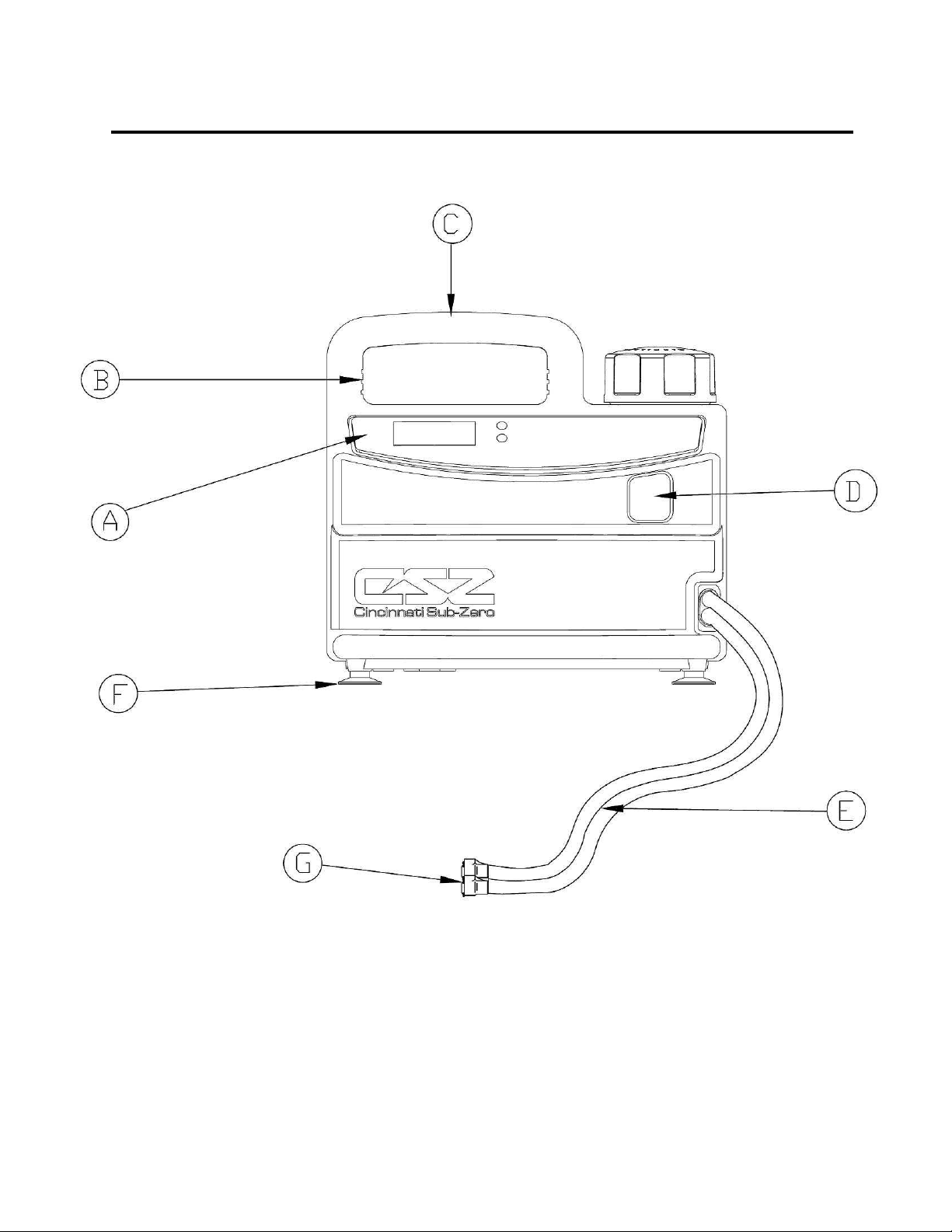
1-4.1. EXTERNAL FEATURES - FRONT VIEW
The external features in Figure (1-1) of the MICRO-TEMP LT unit are described as follows:
A. The membrane on the front of the unit allows the user to change the temperature of
the water flowing through the thermal pad. It displays error messages and sounds
an alarm if there is a problem with the device. Refer to Section (1-4.3) for a list of
controls on the membrane. Refer to Section (3-5) for a list of possible display
messages and alarms.
B. The air vents, on both the top and bottom of the unit, provide air circulation for the
control board.
C. The built in handle permits the operator to grip and pick up the unit when moving it.
D. The sight window allows the operator to visually see how much water is in the
reservoir.
E. The permanently attached hose connects the unit and the thermal pad.
F. The four rubber suction cups on the bottom of the unit prevent the unit from tipping.
G. The coupling attached to the end of the twin black tubing allows a quick disconnect
for the heat therapy pad.
3
INTRODUCTION MICRO-TEMP LT, Model 749
OPERATION AND TECHNICAL MANUAL
FIGURE 1-1. MICRO-TEMP LT, FRONT VIEW
4

INTRODUCTION MICRO-TEMP LT, Model 749
OPERATION AND TECHNICAL MANUAL
1-4.2. EXTERNAL FEATURES - REAR VIEW
The external features in Figure (1-2) of the MICRO-TEMP LT unit are described as follows:
A. The power switch is a beveled rocker switch labeled “I” for ON and “O” for OFF.
B. The fuse housing holds replaceable fuses that are integrated in the switch assembly
to protect against overload conditions.
C. The main power connection is where the detachable power cord connects.
D. The detachable power cord with a hospital grade plug should only be inserted into a
properly grounded receptacle. Electrical specifications are described in Section (7).
E. The water fill opening, secured with a reservoir cap, is where the operator pours
distilled water into the unit to fill the reservoir.
F. The specification label outlines the MICRO-TEMP LT unit's electrical requirements
and the condensed operating instructions allow the operator to see the instructions
and appropriately use the unit.
G. The recessed bottom is used to secure and store the permanently attached hose
and/or the power cord by wrapping the hose and/or cord around the unit when it is
not in use.
H. The equipment grounding terminal is used to perform the ground continuity test.
5

INTRODUCTION MICRO-TEMP LT, Model 749
OPERATION AND TECHNICAL MANUAL
FIGURE 1-2. MICRO-TEMP LT, REAR VIEW
6

INTRODUCTION MICRO-TEMP LT, Model 749
OPERATION AND TECHNICAL MANUAL
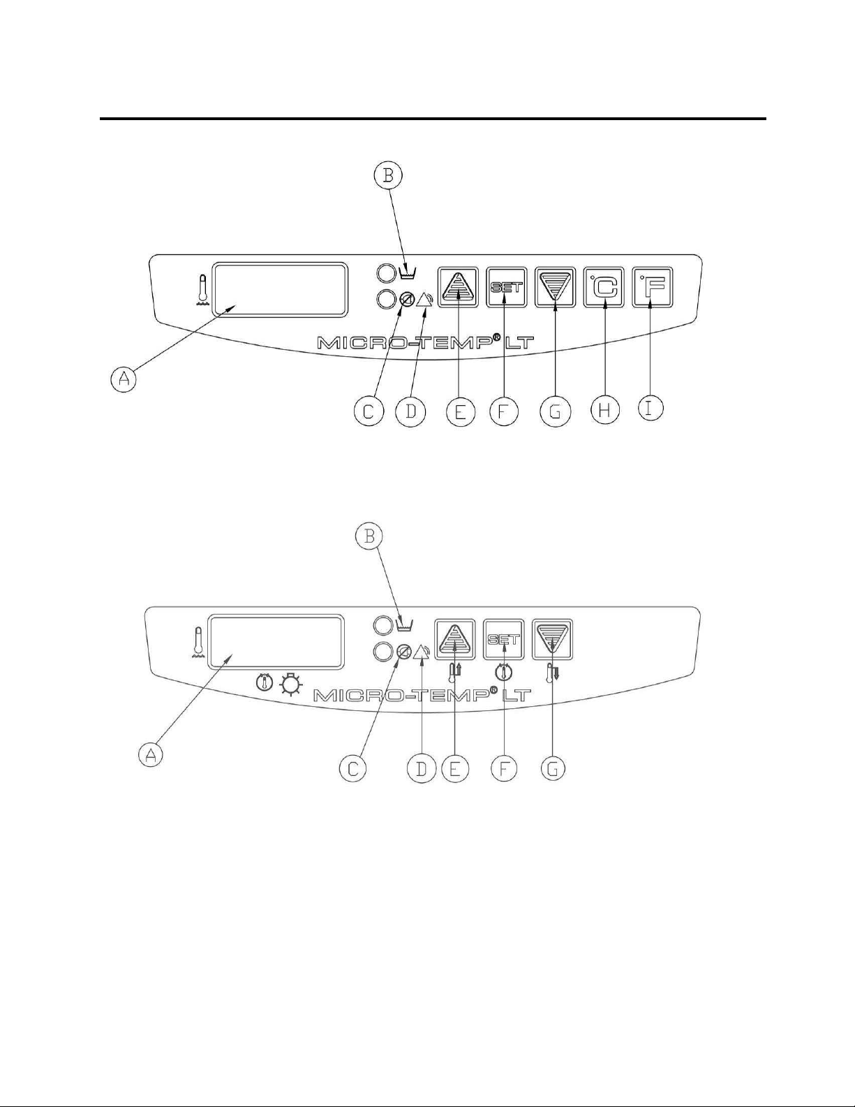
1-4.3. EXTERNAL FEATURES – MEMBRANE CONTROL PANEL
The external features in Figure (1-3) and Figure (1-4) of the MICRO-TEMP LT unit are described
as follows:
A. The digital temperature display shows the actual temperature of the circulating water
and the set point temperature when the “SET” button is depressed. It also displays
alarm messages when a problem occurs, alerting the operator to make a change.
Refer to Section (3-5) for a list of possible display messages and alarms.
B. The “Low Water” symbol indicates when the unit is low on water by illuminating the
yellow LED to the left of the symbol. Refer to Section (3-5), Step (B) for Low Water
Alarm.
C. The “Power Fail” symbol indicates when power has been interrupted by flashing the
red LED to the left of the symbol and sounding an audible alarm. Refer to Section
(3-5), Step (B) for Power Failure.
D. The “Warning” symbol indicates when the water temperature is >1°C (2°F) over the
set point temperature, the water has reached the high limit temperature of 44°C
(111° F), the tilt of the unit is beyond approximately 20˚ in any direction, or when
there is a fault within the unit by flashing/illuminating the red LED to the left of the
symbol and sounding an audible alarm. Refer to Section (3-5), Step (B).
E. The Increment button is used to increase the set point temperature when needed.
F. The “SET” temperature button is used to position the set point temperature.
G. The Decrement button is used to decrease the set point temperature when needed.
H. The “°C” button allows the operator to select Celsius as the measurement scale by
which the unit functions (100V and 115V only).
I. The “°F” button allows the operator to select Fahrenheit as the measurement scale
by which the unit functions (100V and 115V only).
7
INTRODUCTION MICRO-TEMP LT, Model 749
OPERATION AND TECHNICAL MANUAL
FIGURE 1-3. MICRO-TEMP LT, MEMBRANE CONTROL PANEL (100V/115V ONLY)
FIGURE 1-4. MICRO-TEMP LT, MEMBRANE CONTROL PANEL (230/240V ONLY)
8

INTRODUCTION MICRO-TEMP LT, Model 749
OPERATION AND TECHNICAL MANUAL
1-5. REQUIRED ACCESSORIES
The only essential accessory for the MICRO-TEMP LT unit is a thermal pad. Thermal pads are
available with or without a layer of foam bonded to one side and with a non-woven fabric on both
sides to allow moist heat therapy when the foam or non-woven fabric is wetted. They are available
in a variety of sizes. The maximum thermal pad allowed for the MICRO-TEMP LT is 25” x 19”.
The thermal pad is connected to the unit via the permanently attached eight foot (2.4 meter) hose
with “quick-connect” couplings, featuring automatic shut-offs on the end of each hose.
A list of MICRO-TEMP LT System Equipment and accessories are found in Figure (6-8).
1-6. FUNCTIONAL DESCRIPTION OF THE MICRO-TEMP LT SYSTEM
1-6.1. THEORY OF OPERATION
The MICRO-TEMP LT utilizes a linear temperature controller featuring a digital read-out of
water and set point temperature (selectable to indicate Celsius or Fahrenheit for 100V and
115V only), and operates between a temperature range of 20°C to 42°C (68°F to 107°F). In
addition, this model includes audible alarms and visual indicators for power failure and warning
alarms, along with a visual indicator for low water. Safety features include: linear control to
ensure accuracy of temperature setting at all times by eliminating the need for calibration;
digital display of actual water temperature as well as set point temperature; a low water cut-off
switch which shuts off both the heater and circulating pump; an independent high limit sensor to
guard against possible over-heating and subsequent patient injury; and a tilt switch alarm which
sounds and shuts the unit off when tilted more than approximately 20° in any direction from the
horizontal plane.
1-6.2. HEATING SYSTEM
The MICRO-TEMP LT heating system consists of an immersion heater, a water temperature
control, and two high temperature safety devices. Temperature ranges of the system are
described in Section (1-6.4). The immersion heater is located in the reservoir. The water
circulating in the reservoir flows around the immersion heater and is warmed by conductive heat
transfer.
The heating system is operational whenever the control system calls for an increase in the
temperature of the circulating water. It is important to note that the rate of change in the circulating
water temperature is not directly proportional to the rate of change in the temperature of the
patient.
1-6.3. CIRCULATING SYSTEM
The MICRO-TEMP LT circulating water system is composed of a magnetically driven circulating
pump, a single self contained reservoir, a connecting hose, quick-disconnect fittings, and a
localized heat therapy pad.
9

INTRODUCTION MICRO-TEMP LT, Model 749
OPERATION AND TECHNICAL MANUAL
The 0.24-gallon (0.9 liters) capacity reservoir is composed of a single circulating unit.
The circulating water flows over and around the heating element and water temperature sensor
located in the circulating reservoir. The heated water then flows out of the reservoir, to the
circulating pump, through the pump housing and connecting hoses, and then to the localized heat
therapy pad. The water circulates through the pad and returns to the unit to be reheated and
recycled.
In addition, the reservoir contains a low water level sensor which shuts down the heater and
pump, and illuminates the Low Water LED if the water level drops below a preset amount. The
unit becomes operational only after the water level is restored to normal.
1-6.4. TEMPERATURE SAFETY CONTROL SYSTEM
The MICRO-TEMP LT unit is designed to carefully measure and control the temperature of the
circulating water. It is engineered so that when the temperature of the circulating water reaches
the desired set point, the heater cycles in order to maintain the set point temperature. The unit is
designed not to exceed or fall below the desired temperature.
As a safety precaution, the MICRO-TEMP LT unit has a >1°C (2°F) over set point alarm and a
high temperature alarm.
Each safety device continuously monitors the temperature of the circulating water. As an
additional precaution, if the water temperature sensor itself should fail, the unit shuts down and
the display indicates EE05. With this safety design, both the patient and the unit are protected
from injury or damage caused by extreme temperatures.
NOTE: The operator must regularly monitor the patient whenever localized heat therapy is used.
SAFETY CONTROLS FOR PROTECTION FROM HIGH TEMPERATURE
The circulating water reaches 42.0°C ± 0.5°C (107°C ± 1°F), and a microprocessor controls the
set point.
If the circulating water reaches 44°C ± 0.5°C (111°F ± 1°F), a safety device shuts off the heater
and pump, the display alternates between flashing the actual water temperature and flashing “HL,”
an alarm continuously sounds, and the red “Warning” LED illuminates. This alarm condition
cancels only after the unit is powered down.
If the circulating water reaches >1°C (2°F) over th e set point, the display flashes the actual water
temperature, and 2 beeps sound while the red ”Warning” LED flashes. The safety device shuts
off the heater. If the water temperature does not return to the set point temperature after 9
minutes, the device will again sound 2 beeps and the “Warning” LED will flash. The actual water
temperature will continue to flash until the water temperature reaches the set point.
10

GENERAL PREPARATION MICRO-TEMP LT, Model 749
OPERATION AND TECHNICAL MANUAL
SECTION 2. GENERAL PREPARATION OF THE MICRO-TEMP LT
SYSTEM
2-1. INTRODUCTION
This section describes the procedures to prepare the MICRO-TEMP LT unit for general use. This
entails unpacking the shipment, arranging all the equipment for the first time, and completing a test
routine. This section also outlines the bacteriocidal agent preparations, standard safety
precautions, and patient preparation/bedside care when using the hyperthermia pad(s). Technical
support is available upon request.
2-2. UNPACKING THE SHIPMENT
WARNING
• Do not use if the outer casing or membrane control panel is cracked or internal
components are exposed. Contact with internal components could result in
electric shock or thermal injury to the patient or operator.
During the unpacking process, look carefully for signs of shipping damage. If any unacceptable
damage is found, notify the transportation company immediately and file a claim. The
transportation company is responsible for the shipment after it leaves the factory. If problems other
than shipping damage are found, notify your Cincinnati Sub-Zero representative or the Factory.
2-3. FIRST TIME SET-UP/SYSTEM TEST ROUTINE
This section describes the tasks necessary to inspect and arrange the equipment for the first time
after unpacking, and describes a System Test Routine to check the membrane control panel.
The System Test Routine can also be used to teach operators who are unfamiliar with the
equipment how to use the unit.
2-3.1. INSPECTING AND ARRANGING THE EQUIPMENT
A. Place the MICRO-TEMP LT unit in an uncluttered work space that is accessible to the
correct power source with an ambient temperature between
Position the unit so that the membrane control panel faces the operator. See Section
(7) for electrical specifications.
B. Visually inspect the MICRO-TEMP LT unit to determine that there are no missing
parts, unusual dents, or punctures.
C. Examine the power cord for cuts or exposed wires and check the power cord for bent
or missing prongs.
20°C – 35°C (68°F – 95°F)
11

GENERAL PREPARATION MICRO-TEMP LT, Model 749
OPERATION AND TECHNICAL MANUAL
D. Review Section (1-4.1), (1-4.2), and (1-4.3) to identify the features of the MICRO-
TEMP LT unit.
E. Collect and arrange a localized heat therapy pad described in Section (1-5).
CAUTION
• Use distilled water only. Do Not Use De-Ionized water.
• Do not use alcohol. Alcohol may cause pad deterioration.
• Do NOT fill the reservoir to the bottom of the strainer if there is water in the pad.
This could cause an overflow when the unit is turned on.
F. Twist off the cap on the water fill opening and gradually pour approximately .9 liters of
distilled water and two (2) ounces of Propylene Glycol into the reservoir. Stop pouring
when the water reaches the strainer and is visible at the bottom of the water fill
opening.
G. Connect the pad to the MICRO-TEMP LT unit by attaching the pad to the couplings at
the end of the connecting hose. The pad must be connected to one outlet and one
return.
H. Check that the pad is lying flat and that the hose permanently attached to the unit is
not twisted or pinched.
I. Check that the power switch of the unit is OFF.
J. Connect the detachable power cord to the unit.
NOTE: If pad is placed above unit, disconnect pad prior to turning off unit. This could
cause backflow if pad is not disconnected.
WARNING
• Do not by-pass ground on power cord plug. Electrical Hazards may result.
K. Insert the plug into a properly grounded receptacle.
2-3.2. COMPLETING A SYSTEM TEST ROUTINE
After arranging the equipment described in Section (2-3.1), complete the System Test Routine
describing which switches to press and the changes to observe.
NOTE: If power is supplied to the unit and is removed without actuating the power switch (I/O
switch) a power fail alarm is activated. To stop the alarm, restore power to the unit or turn the power
switch to the “O” (OFF) position.
A. Make sure that the power switch is in the "I" (ON) position.
1. The digital temperature display indicates that the unit is on.
12

GENERAL PREPARATION MICRO-TEMP LT, Model 749
OPERATION AND TECHNICAL MANUAL
a. Upon initial power-up, the unit flashes the 42°C default set point
four times, and then flashes the actual water temperature two times
before constantly displaying the water temperature.
2. The pump activates and begins circulating water.
B. Press and hold the “SET” button.
1. The display shows 42°C
C. Release “SET” button.
1. The display reverts back to displaying the actual water temperature.
D. Press the “°F” button (100V and 115V only).
1. The water temperature displayed changes from Celsius to Fahrenheit.
E. Press the “˚C” button (100V and 115V only)
1. The water temperature displayed changes from Fahrenheit to Celsius.
NOTE: If at any time the water falls below a preset limit, the low water sensor is activated
and the Low Water LED illuminates. The unit shuts down and the operator cannot proceed
until this is corrected.
If any of the above are not observed, consult the Troubleshooting Guide in Section (5-12). If they
are observed, continue with the test routine.
WARNING
• Water leaks present a risk of infection to the patient and should be handled
accordingly. Proper sanitation procedures should be followed including, but not
limited to, the preventative maintenance described in this manual. Leaky pads or
hoses should never be used.
F. Check the pad for leaks. If a leak is found, the pad cannot be used. The disposal for
reusable pads is described in Section (4-4).
G. Check the couplings at the end of the hose and pad for positive connection.
NOTE: Set point may be displayed in Fahrenheit if the operator is in Fahrenheit mode (100V
and 115V only). Otherwise the set point is displayed in Celsius.
H. While depressing the “SET” button, press the Down arrow next to the “SET” button.
1. The set point display temperature changes and the numbers move down the
scale. The longer the button is pressed the faster the digits change. When
the button is released and repressed, the digits once again change slowly
and then increase in speed. The lowest setting is 20°C (68°F).
I. While depressing the “SET” button, press the Up arrow next to the “SET” button.
13

GENERAL PREPARATION MICRO-TEMP LT, Model 749
OPERATION AND TECHNICAL MANUAL
1. The set point display changes and the numbers move up the scale. The
longer the button is pressed the faster the digits change. When the button is
released and repressed, the digits once again change slowly and then
increase in speed. The highest setting is 42°C or 107°F.
NOTE: If water temperature is >1°C (2°F) over the set point temperature, the display will
flash and the unit will alarm.
J. To complete this test routine, turn the power switch to the “O” (OFF) position.
1. The display goes blank.
K. Disconnect the power cord from the power source and loosely coil it up, securing it
with the attached velcro tie.
L. For single-use pads, i.e. TEMP-PAD, MAXI-THERM, and MAXI-THERM LITE pads,
follow the instructions packaged with the pad.
The MICRO-TEMP LT unit is now ready for patient use.
2-4. UNIT AND PATIENT RELATED PRECAUTIONS
This unit requires both water and electricity to operate.
Please consult page I, II, and III at the beginning of the manual for a complete list of
warnings and cautions related to the MICRO-TEMP LT.
A. Anytime the unit sounds an alarm, the operator should immediately check the status
display and act accordingly (e.g., add water, remove from service, etc.). See
Section (3-5) for status display and alarm messages.
B. The MICRO-TEMP LT unit is equipped with fuses in the I/O power switch to protect
against current overload.
2-5. PATIENT PREPARATION AND BEDSIDE CARE
Effective use of the MICRO-TEMP LT system must include proper patient care prior to and while
using the hyperthermia pad(s).
14

GENERAL PREPARATION MICRO-TEMP LT, Model 749
OPERATION AND TECHNICAL MANUAL
WARNING
• A physician's order is required for setting pad temperature and use of equipment. As
directed by physician, check the patient's temperature and skin condition of areas in
contact with the pad. Check the pad water temperature. Pediatric patients, temperaturesensitive patients with vascular disease, surgical patients, diabetics, and Raynauds
disease patients should be checked more frequently. Notify the physician promptly of
any change in patient status in order to avoid serious injury or death. Failure to
inform the physician of any deviation may result in injury to the patient.
Pediatrics – Infants and children body temperature are more responsive to
surface heating than adults. Due to their size, the effect of heating a child is
more pronounced because of their higher ratio of skin contact area to body
mass.
Temperature Sensitive Patients – Patients with impaired peripheral blood
circulation and patients who are incapacitated may be more sensitive to
temperature changes than patients with normal circulation.
Surgical Patients – Patients with poor circulation due to inadequate heart
function, loss of blood, or impaired peripheral blood circulation may be more
sensitive to temperature changes.
• If device is used at home, patient must follow directions prescribed by their
physician and be aware of all warnings and cautions mentioned throughout the manual.
• Observe patient’s skin condition frequently due to individual differences in
sensitivity and susceptibility to injury from heat and/or externally applied chemicals
or pressure. Patients at greatest risk are those unconscious, on prolonged
therapy, diabetics, children, and persons incapacitated, with sensitive skin areas,
or poor circulation.
• Do not use for ECMO (Extracorporeal Membrane Oxygenation) therapy.
• The method of temperature control provided by all localized heat therapy units presents
the danger of heating body tissues, particularly the skin, to a point where they are injured,
i.e., burns. Depending on the extent and severity of a burn, very serious complications
may arise.
• Prevent excessive and/or prolonged tissue pressure and shearing forces, especially over
bony prominences, to prevent skin damage that may result.
• Do not place additional heat sources between the patient and pad. Skin damage may
result.
• Do not use the MICRO-TEMP LT system in the presence of flammable anesthetics. Risk
of explosion can result.
• Do not position unit near any objects that can generate a strong electrical/magnetic
field. Potential electromagnetic interference may result.
• The display may blank momentarily during an electrostatic discharge event, but the
essential performance of the unit is not affected and no harm will occur to the patient. If
an electrostatic discharge event occurs, check to see if unit is operating properly. If unit
does not return to previous operation, turn unit off then back on and reset temperature
settings as prescribed.
• Do not wrap pad so tightly as to constrict blood flow. Do not use pins to secure pad or
hoses. Do not allow pad or hoses to come in contact with any sharp object.
15
 Loading...