

Page 1
OPERATION
MANUAL
ELECTRI-COOL® II
MODEL 767
Page 2

Table of Contents
1.0
2.0
3.0
4.0
5.0 Set Up / Operation / Cleaning
6.0 Specifications
7.0 General Maintenance and Checkout Procedures
7.10
7.11
8.0 Troubleshooting Guide
Warnings / Cautions
Symbols
Receiving and Inspection
Approvals
Introduction
4.1
Purpose 6
4.2
Clinical Indications 6
4.3
Contraindications 7
4.4
Description 7
4.5
Accessories 8
4.6
Transporting and Storing 9
5.1
Equipment Set Up 9
5.2
Filling Instructions 11
5.3
Startup Instructions 11
5.4
Setting Temperature 11
5.5
Pad Instructions 14
5.6
Disposal 14
5.7
Cleaning 14
5.8
Storage 14
7.1
Exterior Physical Inspection 16
7.2
Air Filter Inspection
7.3
Flow Test
7.4
Temperature Test 16
7.5
Low Water Switch/Alarm Test 16
7.6
Leakage Current Test 17
7.7
Ground Continuity Test 17
7.8
Internal Heatsink High-Limit Thermostat Test/ Redundant Internal Heatsink
High-Limit Thermal Fuse Test
Water Temperature Low-Limit Thermistor Test 17
Internal Physical Inspection 17
3
5
9
15
16
16
17
19
6
6
6
16
8.1
General 19
8.2
Alarm Indications 19
9.0 Parts List
10.0
11.0
Fluid Circuit Disinfection/Dry Storage Procedure
Customer Service & Support
20
23
27
56269-D ECN M508-3187
Page 2 of 27
Page 3
• Read Operation Manual before operating.
• At least every 20 minutes, check patient’s temperature and skin condition of areas in contact with
blanket; also, check blanket water temperature. Pediatric, temperature-sensitive patients with
vascular disease, and operating room patients should be checked more frequently. Notify physician
promptly of any change, or if the patient’s temperature is not responding properly, or does not
reach the prescribed temperature in the prescribed time, or there is a change in the prescribed
temperature range. Failure to inform physician of the deviation may result in injury to the
patient.
• Observe patient’s skin condition frequently due to individual differences in sensitivity and
susceptibility to injury from cold and/or externally applied chemicals or pressure. Patients
at greatest risk are those unconscious, on prolonged therapy, diabetics, children, and
persons incapacitated or with insensitive skin areas or poor circulation.
• Prevent excessive and/or prolonged tissue pressure and shearing forces, especially over bony
prominences to prevent skin damage that may result.
• Do not place additional cold sources between the patient and blanket. Skin damage may result.
• The area between the patient and the blanket should be kept dry to avoid injury to patient.
• Do not wrap pad so tightly as to constrict blood flow. Do not use pins to secure pad or
hoses. Do not allow pad or hoses to come in contact with any sharp object.
• Do not use the Electri-Cool® II system in the presence of flammable anesthetics. Risk of explosion
can result.
• The Electri-Cool® II system has been designed and tested according to UL-60601-1 and has passed
testing regarding the reception and emission of electromagnetic interference. However, operation of
the Electri-Cool® II system near sources of electromagnetic interference or near sources that may
receive electromagnetic interference may cause abnormal operation of this unit or other devices. If
interference of this type is observed, re-locate the unit away from such devices.
• Power interruption will cause the Electri-Cool® II to revert to the default range of 40°F-45°F (5°C-7 °C).
Follow instructions for First Time Set-Up/System Test Routine to resume operation. Failure to
resume the desired therapy could result in injury.
• This device is still energized when the inlet switch is in the off position. To completely
disconnect the device from the power source, remove the appliance plug from the back of the
unit.
• Electric shock hazard. Do not remove cover. Service to be performed by qualified
personnel only.
• For continued protection against risk of fire, replace only with same type and rating of fuse.
WARNING
Page 3 of 27
Page 4

CAUTION
• Use distilled water only. Failure to use distilled water may result in poor performance and/or
damage to the Electri-Cool® II voiding the warranty.
• Do not use De-ionized Water. The majority of de-ionizers do not maintain a neutral pH of 7. If the
de-ionized water is acidic, it will cause a battery effect, the metal will begin to deteriorate and may
cause a leak in the system.
• Do not use alcohol. Alcohol may cause blanket deterioration.
• Do not overfill. Overfilling may result in overflow when the water in the blanket drains back into the
system when the system is turned off.
• Power cord has “HOSPITAL GRADE” plug (domestic units only). Grounding reliability can
only be achieved when connected to an equivalent receptacle marked “HOSPITAL
GRADE.”
• Do not operate pump without a pad connected or with pad clamps in the “CLOSED” position.
Always check clamps to make sure they are fully open.
• Check hose couplings to be certain they are properly locked together.
• Make sure hose and pads are free of kinks that might restrict flow.
• Complete folding of pad may restrict flow and reduce therapy to patient.
• The pad surface should be checked for damage prior to each application.
• To ensure maximum therapy is delivered, it may be necessary to retain the pad on the patient with
straps for adequate contact with the patient.
• Follow Pad instructions and Hospital/Physician instructions for applying, storing, and disposal of
product.
Page 4 of 27
Page 5
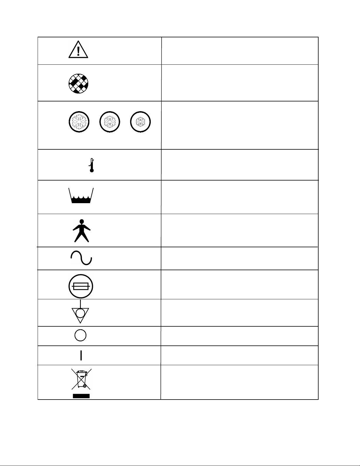
1.0 Symbols
See Accompanying Documentation
Inspect and Change Filter Periodically
5 - 7°C 8 - 10°C 11 -13°C
40 - 45°F 46 - 50°F 51 - 55°F
Temperature Settings
2°C/36°F
Low Water Temperature
Low Water Level
Type B Applied Part
Voltage, Alternating Current
Externally Accessible Fuse Rating
Potential Equalization Connection (Grounding)
Power OFF ( Located on Switch)
Power ON (Located on Switch)
Separate collection for electrical and Electronic
equipment
Page 5 of 27
Page 6
2.0 Receiving Inspection
2.1 After unpacking the Electri-Cool ® II Cold Therapy Unit, inspect the system for concealed damage.
Retain all packing material and carefully record or photograph any damage. Notify the carrier at once
and ask for an inspection (in writing). Failure to do this within 15 days may result in loss of claim. Do
not return the equipment to Cincinnati Sub-Zero. Call our Medical Technical Service department for
further instruction.
3.0 Approvals
3.1 General Safety and Electrical Safety
Classified by Underwriters Laboratory Inc. ® with
respect to Electric Shock, Fire and Mechanical
Hazards only in accordance with UL 60601-1,
CAN/CSZ-C22.2 No. 601-1, 5R37
5R37
3.2 Electromagnetic Compatibility (EMC)
Tested and passed in accordance with IEC 60601-1-2 EMC requirements
3.3 European
4.0 Introduction
4.1 Purpose
The purpose of this manual is to provide operation and maintenance instructions for the Electri-Cool ®
II Cold Therapy Unit.
4.2 Clinical Indications
Cold therapy has been found to be clinically effective in accelerating the healing of damaged tissue,
and in retarding metabolism within the tissue cells.
Localized cold therapy is used in the operating room, recovery room, intensive care unit, physical
therapy, and in individual patient rooms. It is used effectively to treat surgical incisions, as well as
wounds and inflammation caused by traumatic injury. It is prescribed with many types of surgery, for
example:
• Orthopedic (Arthroscopy, Anterior Cruciate Ligament Repair, Arthroplasty for Hip, Knee, and other
Total Joint Replacement)
• Neurologic/Orthopedic (Laminectomy)
• Abdominal (Hernia, Cholecystectomy)
• Oral/Maxillofacial/Plastic (Dental Extractions, Rhinoplasty, Augmentations, Face Lifts)
• Urological (Vasectomy, Prostatectomy, Urological Implants)
• Obstetrical/Gynecological (“C” Section, Episiotomy, Hysterectomy)
In compliance with the Medical Device Directive 93/42/EEC
Page 6 of 27
Page 7
In most cases, cold therapy is applied immediately following the surgical procedure directly to the
wound site. This acts to help reduce swelling and pain, while also helping to reduce or eliminate the
need for pain-killing medications. For the specialty of hand surgery, cold therapy is also applied to the
upper extremity before and during the procedure in conjunction with a tourniquet.
Other conditions indicating the application of cold therapy are:
• Acute injuries • Chronic pain
• Alopecia • Low back pain
• Arthritis • Muscle spasms
• Bruises/contusions • Sprains
• Cellulitis • Strains
4.3 Contraindications
Observe patient's skin condition frequently due to individual differences in sensitivity and susceptibility
to injury from cold and/or externally applied chemicals or pressure. Patients at greatest risk are those
unconscious, on prolonged therapy, diabetics, children, and persons incapacitated or with insensitive
skin or compromised circulation.
4.4 Description
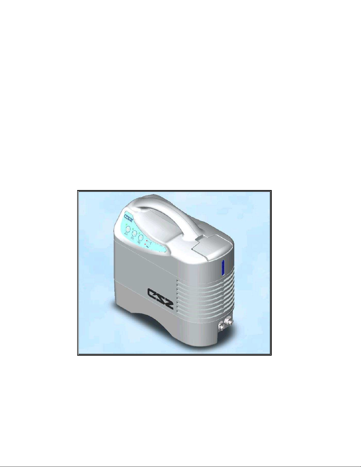
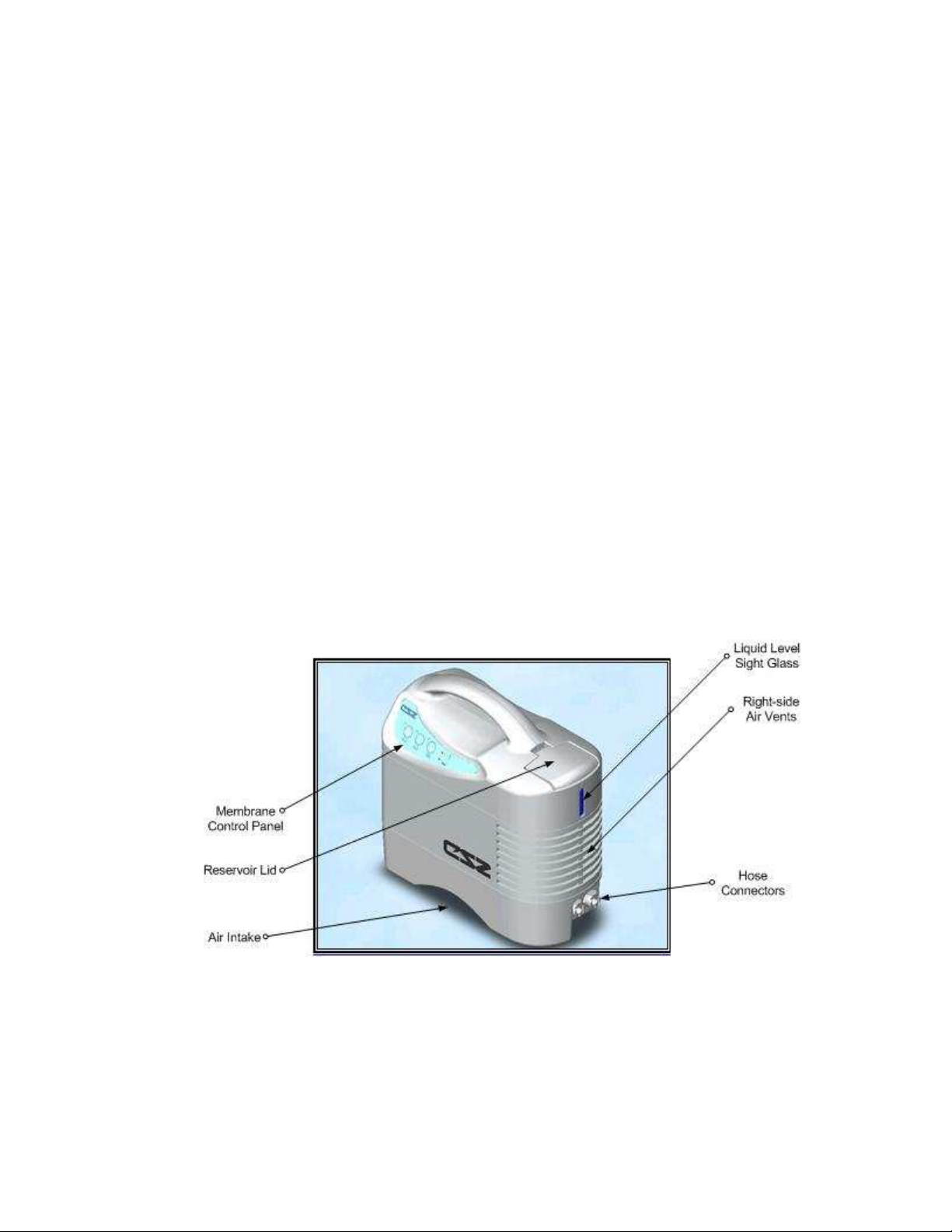
The Electri-Cool® II Cold Therapy Unit has been designed to provide maximum thermal transfer
efficiency at optimum safety. The Electri-Cool® II consists of a plastic reservoir for holding distilled
water; a float switch to sense water level; a pump for circulating water through an external pad; a
thermoelectric sub-assembly to cool the water; a microprocessor-based electronic control to regulate
water temperature; and a fan to transfer absorbed heat to the ambient air. The user can select
among three pre-set temperature ranges: 51ºF-55ºF (11ºC-13ºC); 46ºF-50ºF (8ºC-10ºC); and 40ºF45ºF (5ºC-7ºC). In addition to the aforementioned features, this model includes audible alarms for low
temperature and low water with visual indicators. The unit also shuts down entirely in the event of an
internal component over temperature condition.
Figure 1.1: Electri-Cool® II Front View
Page 7 of 27
Page 8
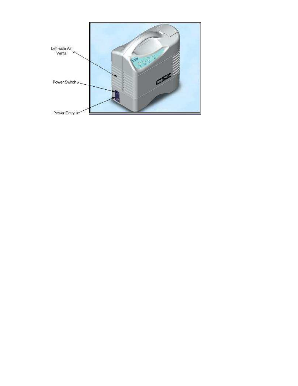
Figure 1.2: Electri-Cool® II Left-side View
4.5 Accessories
The essential accessories for the Electri-Cool® II Unit are listed below:
The Thermal Pads consist of two layers of plastic sealed together to provide multiple passageways for
water flow in a random-flow pattern designed to prevent occlusion.
Temp-Pad® Localized Cold Therapy Pads
Urethane with Foam Backing Sterile w/o Straps Sterile w/Straps
3” x 5” (7.6cm x 12.7cm) 305-USS
3" x 18" (7.6cm x 45.7cm) 318-US
5" x 10" (12.7cm x 25.4cm) 510-US 510-USS
8" x 14" (20.3cm x 35.6cm) 814-US 814-USS
11" x 10" (27.9cm x 25.4cm) CT-99
11" x 12" (27.9cm x 30.5cm) 1112-US 1112-USS
12" x 15" (30.5cm x 38.1 cm) 1215-US
ImmobilICE® Supports consist of a Temp-Pad® Pad contained within a polypropylene felt body,
brushed nylon outer laminate and Tietex 100% polyester with hook and loop closures.
ImmobilICE® Supports, Sterile
Universal Back Support 814-IMB
Universal Hip Support 814-IMH
Temp-Pad Wraps
Shoulder Wrap - small/medium 707-WSS
Shoulder Wrap - large/x-large 707-WSL
Knee Wrap 707-WKN
The pads are connected to the unit via a hose with self-sealing “quick-connect” couplings containing
automatic shut-off valves at each end.
Insulated Hose
Insulated Connecting Hose, 6' (1.83m) 757-HIN
Other Accessories
Bed Bracket 767-BBK
Disposable Filter 767-FIL
Mobile Stand (Requires 767-BBK) 767-MST
Page 8 of 27
Page 9
4.6 Transporting and Storing
Drain all water from the reservoir before shipment or storage. The Electri-Cool® II unit can be transported via
normal shipping methods via ground, air, or water when packaged in its approved packaging material.
During transportation and storage, packaging should not be exposed to conditions that fall out of the ranges
below:
4.6.1 Temperature: -40°C to 70°C (–40°F to 158°F)
4.6.2 Humidity: 10% to 100%
4.6.3 Atmospheric Pressure: 500 to 1060hPa (7.25 to 15.37 PSIA)
5.0 Set Up / Operation / Cleaning & Storage
5.1 Equipment Set Up
5.1.1 Before use, check the air filter for accumulated dust. If filter is dirty, replace the filter with a new
one. Refer to, “General Maintenance and Checkout Procedures”, for filter replacement
instructions.
5.1.2 Check to ensure that the water level in the reservoir is at its maximum level. The maximum level
is at the lowest level of the fill spout (or threaded neck). Refer to “Filling Instructions”.
Use distilled water only. Failure to use distilled water may result in poor performance and/or
damage to the Electri-Cool® II voiding the warranty.
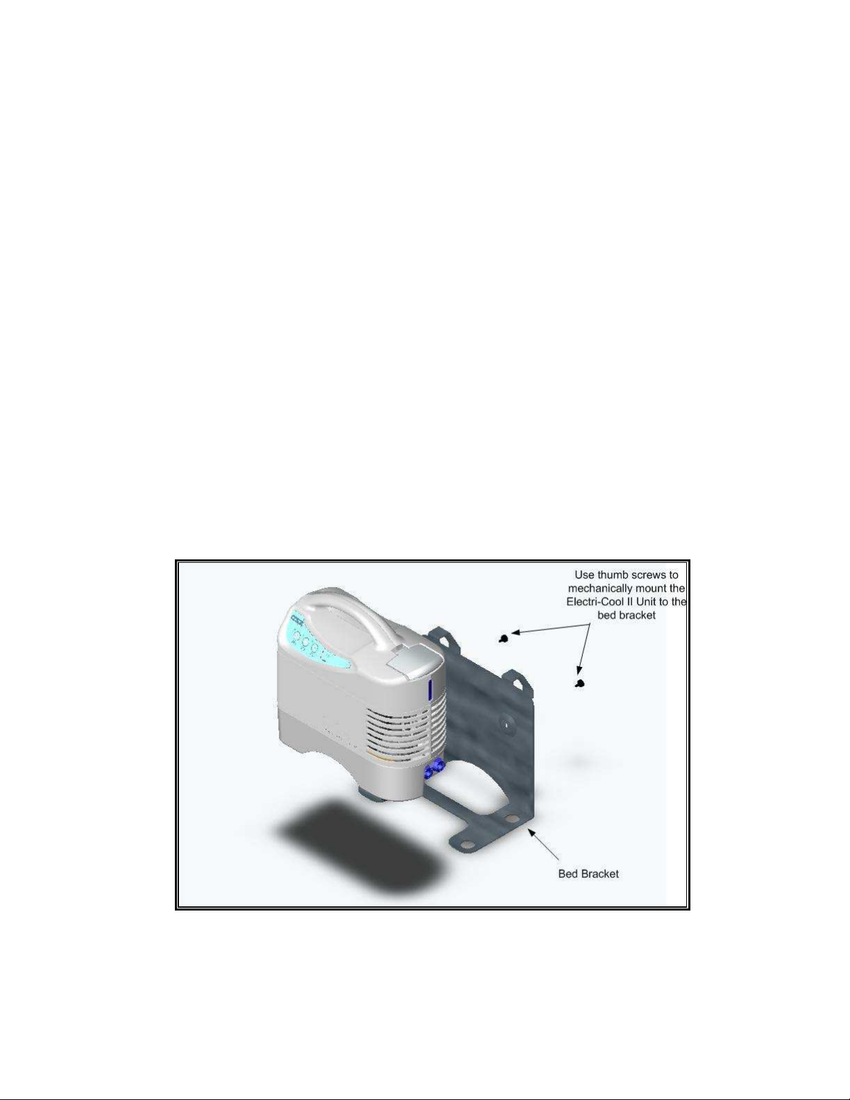
5.1.3 The Electri-Cool® II unit should be placed on a secure, flat surface at least 61cm (2 feet) from
any wall or object that may restrict airflow to the unit. A bed bracket or mounting stand as listed
in “Accessories” section can also be used within proximity of the patient such that the attached
hoses will reach the desired therapy site.
Figure 5.1: Mounting the Electri-Cool II to the Bed Bracket
Page 9 of 27
Page 10
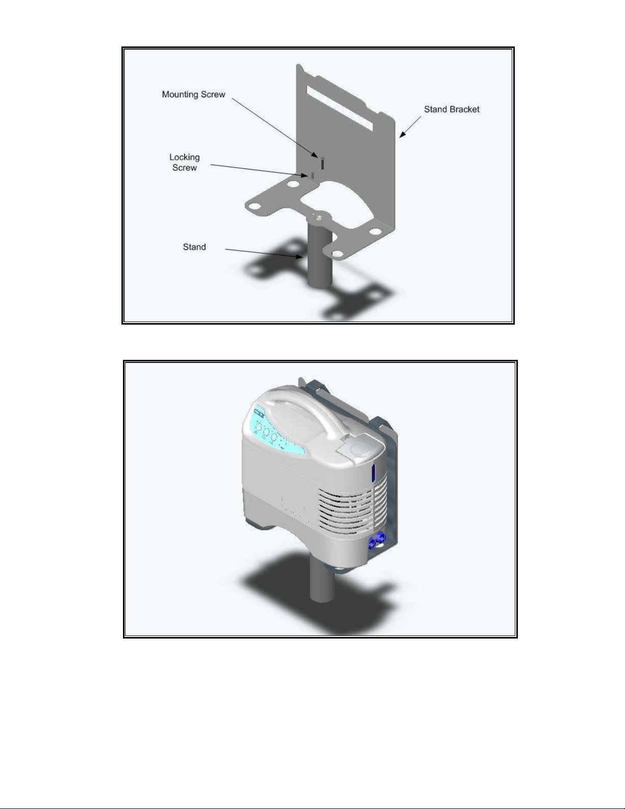
Figure 5.2: Mounting Stand Bracket to Stand Assembly
Figure 5.3: Mounting the Electri-Cool II to Stand
Page 10 of 27
Page 11

5.2 Filling Instructions
5.2.1 Lift the reservoir lid and fill reservoir with distilled water to its maximum level. The maximum
5.2.2 Select a CSZ pad and insert the male couplings from the pad into the female couplings
5.3 Startup Instructions
5.3.1 Plug the power cord into a grounded receptacle providing the proper voltage and
5.3.2 Press the power switch to the “ON” position. Electri-Cool® II Unit will then go into a startup
5.3.3 The Electri-Cool® II Unit is now ready to use.
5.4 Setting Temperature
5.4.1 The Electri-Cool® II Unit must be filled with distilled water and connected to a pad before
5.4.2 Select a temperature range among the three possible settings:
1. 11ºC-13ºC (51ºF-55ºF)
5.4.3 A visual light (temperature indicating LED) located in the upper-left area of the selected
level is at the lowest level of the fill spout (or threaded neck). Close the lid.
Use distilled water only. Failure to use distilled water may result in poor performance
and/or damage to the Electri-Cool® II voiding the warranty.
on the hose. Make sure couplings are locked together tightly. Check the clamps on the
pad making sure they are fully open. The hose and pad must be free of kinks that might
restrict flow. Refer to Section “Pad Instructions”.
Note: Optimum operation is obtained when water level is well above to low water level
marked “MIN”. The low water cut-off switch will activate before the water level reaches the
bottom of the window
frequency.
sequence for approximately one minute. During this sequence check to make sure that
all audible and visible alarms are working. Check to make sure that there is water flow
through the pad. Check water level and refill with cool distilled water if necessary.
attempting to set temperature.
2. 8ºC-10ºC (46ºF-50ºF)
3. 5ºC-7ºC (40ºF-45ºF)
button will indicate the selected range. Allow fifteen to twenty minutes for the water to
reach selected temperature. The time required for the unit to reach the set point depends
on the pad used and the ambient temperature. The time may also very from patient to
patient.
Page 11 of 27
Page 12
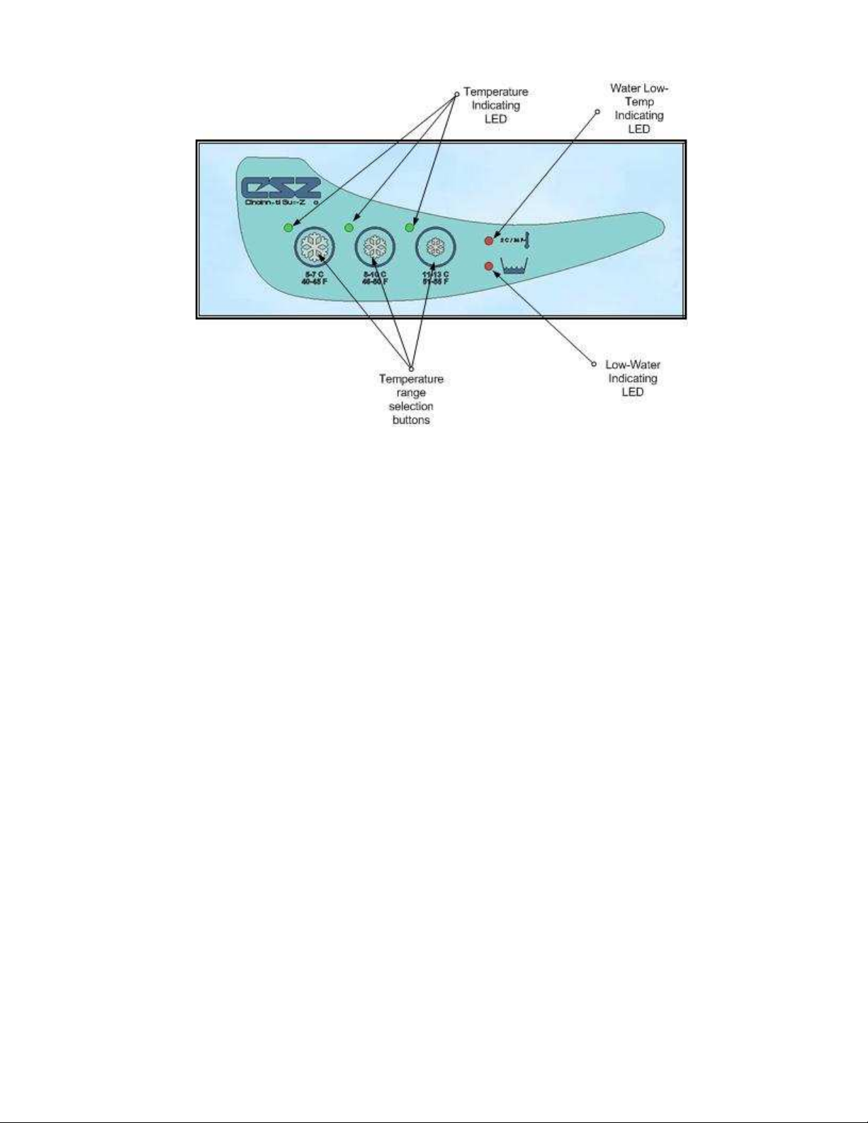
Figure 2.1: Membrane Control Panel
Page 12 of 27
Page 13
6.0
• At least every 20 minutes, or as directed by physician, check patient’s skin condition of areas
in contact with blanket; also, check blanket water temperature. Pediatric, temperaturesensitive patients with vascular disease, and operating room patients should be checked
more frequently. Notify physician promptly of any change, or if the patient’s treatment
is not responding properly. Failure to inform a physician of the deviation may result
in injury to the patient.
• Observe patient’s skin condition frequently due to individual differences in
sensitivity and susceptibility to injury from cold and/or externally applied
chemicals or pressure. Patients at greatest risk are those unconscious, on
prolonged therapy, diabetics, children, and persons incapacitated or with
insensitive skin areas or poor circulation.
• Prevent excessive and/or prolonged tissue pressure and shearing forces, especially over
bony prominences, to prevent skin damage that may result.
• Do not place additional heat or cold sources between the patient and blanket. Skin damage
may result.
• The area between the patient and the blanket should be kept dry to avoid injury to patient.
• Do not wrap pad so tightly as to constrict blood flow. Do not use pins to secure
pad or hoses. Do not allow pad or hoses to come in contact with any sharp object.
WARNING
• Do not operate unit without a pad connected or with pad clamps in the “CLOSED”
position. Always check clamps to make sure they are fully open.
• Check hose couplings to be certain they are properly locked together.
• Make sure hose and pads are free of kinks that might restrict flow.
• Complete folding of pad may restrict flow and reduce therapy to patient.
• The pad surface should be checked for damage prior to each application.
• To ensure maximum therapy is delivered, it may be necessary to retain the pad on the
patient with straps for adequate contact with the patient.
• Follow Pad instructions and Hospital/Physician instructions for applying, storing, and
disposal of product.
CAUTION
Page 13 of 27
Page 14

5.5 Pad Instructions
The Electri-Cool® II has been designed and tested to be used with CSZ thermal pads. Use of nonCSZ manufactured pads may not produce the same results. CSZ pads allow maximum flow while
resisting restriction or kinks. The unique foam-layered side or non-woven covered sides offer
maximum patient comfort.
5.5.1 Read and understand operation manual before connecting pad to Electri-Cool® II unit.
5.5.2 Read and understand pad application instructions accompanying CSZ pad.
5.5.3 Connect hose to unit by inserting connectors on hose into connectors on unit.
5.5.4 Apply pad to patient and attach pad to hose by inserting connectors on pad into hose
5.5.5 If the pad has clamps, make sure clamps on tubing of pad are open.
5.5.6 Turn unit “ON” and set to temperature.
5.5.7 After pad has filled, check water level in unit. Add distilled water, only if necessary.
5.5.8 When therapy is no longer needed, turn unit “OFF”. Unplug power cord from the outlet.
5.5.9 If the pad has clamps, close clamps on pad.
5.5.10 Disconnect pad from hose by depressing metal clips. Dispose of pad.
5.6 Disposal
Medical Devices that have come in contact with patients contain the risk of bio-contamination. This
device generates no waste products or residues under normal use and normal cleaning routines.
Follow State and Hospital guidelines regarding disposal of medical devices at the end of their useful
lives.
5.7 Cleaning
The Electri-Cool® II Unit case is constructed of plastic. Wipe outer surface with a cloth soaked in a
solution of water and mild detergent. Rinse cloth of excess solution before applying to unit. Contact
the Cincinnati Sub-Zero Technical Service Department for information on the Decontamination
Cleaning procedure. Users should not use cleaning or decontamination methods different from those
recommended by the manufacturer without first checking with the manufacturer that the proposed
methods will not damage the equipment.
5.8 Storage
Drain the reservoir completely before storage of the Electri-Cool® II unit. Contact the
Cincinnati Sub-Zero Technical Service Department for the reservoir disinfection procedure.
Connectors should “click” as they lock together.
connectors. Normal use of the pad is to be applied in direct contact with the patient. Pad
may be used over or under a patient, in the flat state or wrapped around patient.
Page 14 of 27
Page 15

6.0 Specifications
Electri-Cool® II
Physical Model 767
Size 29.2cm W x 15.24cm D x 30.5cm H
(11.5"W x 6.0"D x 12.0"H)
Dry Weight 5.9 kg (13 lbs.)
Hose length 1.83 m (6 ft.)
Portability Molded, attached, carrying handle
Connectors Quick-connect, self-sealing
Case Material G.E. Cycoloy 6600 Plastic
Case Color Light Grey
Control System
Type Microprocessor –controlled
Mode of Operation Continuous
Cooling System
Temperature Range 5°- 13°C (40°- 55°F )
Electrical System
Type of Shock Protection Class I
Degree of Shock Protection Type B Applied Part
Voltage 100-240VAC, 50-60Hz.
Current 3.5 Amp.
Fuse 5 Amp rated at 250V 5mm x 20mm Time Delay
Qty. 2: Line and Neutral
Power Cord 115V & 100V - 3 conductor, 16/18 AWG, 10’ molded hospital
grade plug
230 V – 3 x 1.00mm, 10A, 2.5 m
Leakage Current Under 50 microamps
Circulating System
Reservoir Capacity 976mL (33 oz.)
Reservoir Fluid Distilled water
Fill Cap Vented
Flow Rate (thru pad) 38 LPH (10 GPH)
Water Level Indication Translucent window to reservoir
Low Water Cut-Off Switch Yes (thermoelectrics and pump)
Storage Dry
Degree of Water Ingress IPX0 Rated Equipment
Protection
Safety System
Overheat Protection Internal and power supply heatsink 65.6ºC (150ºF)
Low water 650 mL (22oz)
Low water temperature 3°C (36°F)
Warning Lights Low Temp and Low Water LED’s
Audible Alarms Low Temp and Low Water
Classified to UL 60601-1 Yes
Classified to IEC 60601-1-2 Yes
Page 15 of 27
Page 16
7.0 General Maintenance and Checkout Procedures
It is suggested you perform the following procedures in their order of listing and document the results on a
Preventive Maintenance Inspection Record. Refer to Table 7.0 for an example of an inspection form.
7.1 Exterior Physical Inspection
Look for cracked, bent, missing, or otherwise damaged parts. Carefully inspect the power cord for
cuts or exposed wire. Check the plug for missing or bent pins. Remove the fuse and make sure it is
the same type and rating as described on top of the unit.
7.2 Air Filter Inspection
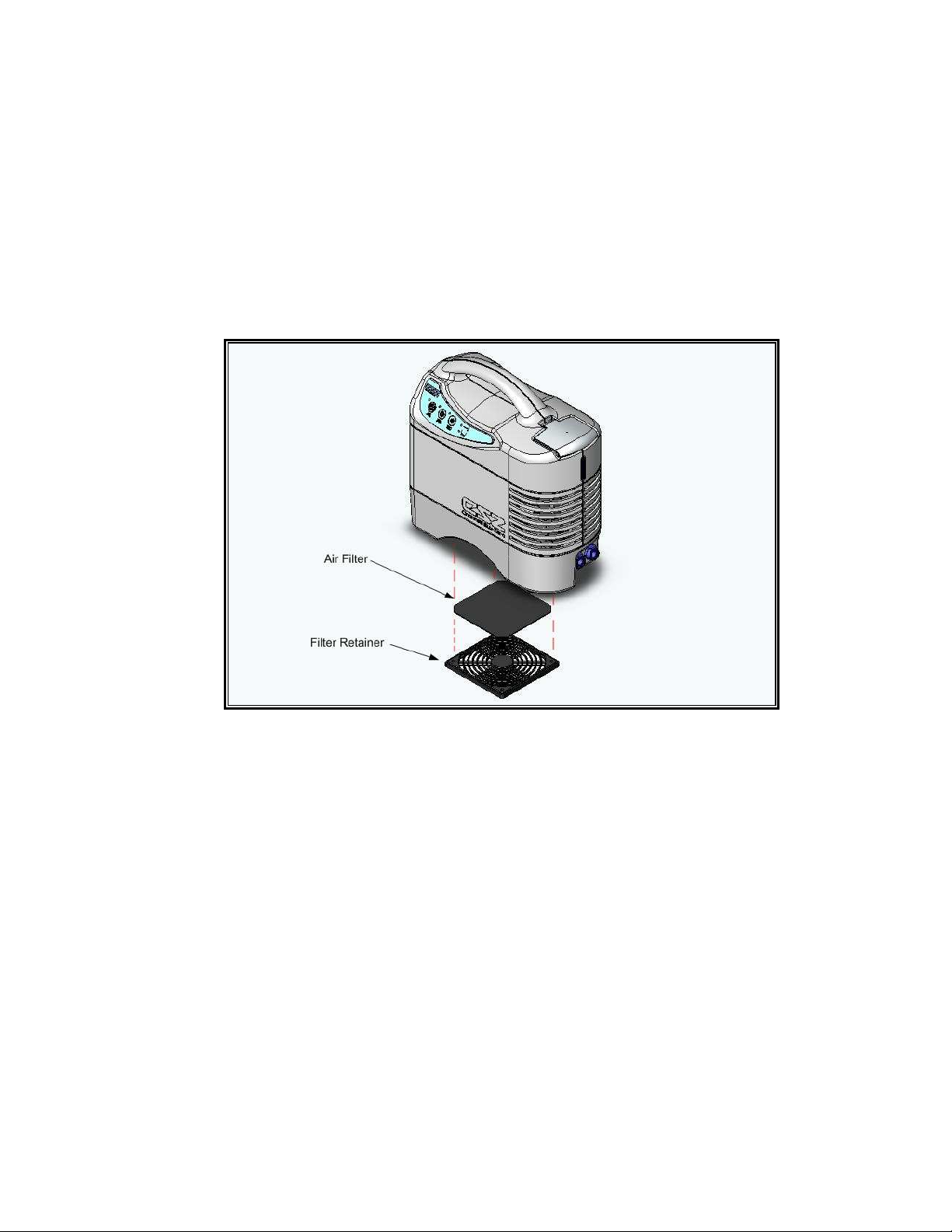
Inspect filter before each use of unit. Remove air filter retainer to access the air filter on the bottom of
the unit. Inspect the filter for accumulated dust. If the filter is 30% clogged with dust, replace filter with
a new one and reattach the air filter retainer.
7.3 Flow Test
Maximum flow rate is obtained with water temperature at room temperature and the pad laying flat on
a smooth surface. If no flow rate is observed, check for kinks in the pad or hose, clamps closed on
pad, or couplings not properly seated and locked together, or reversed connections to the pump.
Allow water temperature to reach room temperature, and check flow rate with a flow meter. If the flow
rate is substantially less than 38 LPH (10 GPH), check the pump and/or pad/hose for restrictions.
See Trouble Shooting Guide.
7.4 Temperature Test
Set Temperature to the coldest setting, 5-7°C (40-45°F). Let pump run 60 minutes to allow internal
operating temperatures to stabilize before performing this test. Insert a digital Thermistor (series 400)
probe into the outlet water flow stream. Note temperature every 30 seconds for five minutes, (10
readings). Record the average of these readings. The readings should fall within the selected
temperature range on digital readout. Temperature swings should not exceed ± two degrees
Fahrenheit out of the selected range.
7.5 Low Water Switch/Alarm Test
To perform this test, first open the reservoir access lid. Reach into the reservoir to the float switch
and push the float all the way down to it lowest possible position. The low water alarm should sound
along with the illumination of the low water level LED located on the membrane control panel. The
unit will stop pumping water and stop cooling immediately. Release the float and let it gravitate to its
highest position. The unit should now resume normal operation.
Page 16 of 27
Page 17

7.6 Leakage Current Test
Connect ground lead clamp of leakage current tester to the ground lug on the back of the unit. Plug
unit into tester. Test unit in all combinations of power switch off and on, normal and reverse polarity,
and normal and open ground. Record highest reading. If more than 50 microamperes, refer to
Troubleshooting Guide. Disconnect current leakage tester set-up. Unplug power from the unit.
7.7 Ground Continuity Test
Using an ohmmeter, measure the resistance between the ground lug and the ground pin of the power
plug. This value shall not exceed 0.2 ohm. If higher than 0.2 ohm, see Troubleshooting Guide.
7.8 Internal Heatsink High-Limit Thermostat Test/Redundant Internal Heat Sink -Limit Thermal
Fuse Test
Locate J4 connector on control board. Remove connector. Unit should alarm.
7.9 Water Temperature Low-Limit Thermistor Test
With a decade box insert connector to the low limit thermistor connector on control board, while
continuing to close the thermostat and thermistor. Set the resistance on the decade box to 2.22°C
(36°F). The low limit alarm should sound along with the illumination of low limit LED on the membrane
control panel. The unit will stop pumping water and stop cooling immediately. Reset the resistance on
the decade box to 2.78°C (37°F). The unit should no w resume normal operation.
7.10 Internal Physical Inspection
While the side enclosure is removed, carefully inspect the unit for any signs of leaks, loose
components, or damage. Check wiring for breaks in insulation, exposed wires, loose connections, etc.
Repair or replace components as necessary and retest unit before placing back into service. Once
inspection is complete, replace enclosure. Note: screws for enclosure are to be tightened to 10 in-lb
of torque. Run unit long enough to assure that all connections have been properly made and the
pump is in good working order.
Page 17 of 27
Page 18

Table. 7.0 Sample - Preventive Maintenance Inspection
Procedure 1/1/04 3/1/04 6/1/04
1.
Exterior physical inspection OK
2.
Air-filter inspection OK
3.
Flow test—Insert value 10 GPH
4.
Temperature test—Insert value 42
5.
Low water switch test OK
6.
Leakage current test—Insert value 50µµµµA
7.
Ground continuity test—Insert value .09ΩΩΩΩ
8.
Internal heatsink Hi-limit thermostat test— Insert value OK
9.
Redundant internal heatsink Hi-limit thermostat test—insert value OK
10.
Water temperature low-limit thermistor value test—insert value OK
11.
Internal physical inspection OK
°°°°
F
Page 18 of 27
Page 19
8.0 Troubleshooting Guide
8.1 General
This section provides information to aid the service technician in diagnosing problems with the Electri-
Cool® II Cold Therapy Unit. The left column lists problems that could occur; the right column lists the
most probable causes.
Problem Probable Cause
Unit will not turn on. 1. Unit not plugged into proper voltage supply.
2. Blown fuse.
3. Loose connector.
Unit turns on, but will not pump 1. Kinks in pad/hose.
2. Improper connections to pad/hose.
3. Improper connections to P.C. board.
4. Defective P.C. board.
Unit will not cool. 1. Air filter clogged.
2. Air intake blocked.
3. Air outlet vents restricted.
4. Defective P.C. board
Low water warning light/audible on. 1. Reservoir water level too low.
2. Unit Tilted
3. Defective P.C. board(s).
Low temp warning light/audible on. 1. Water used to fill pump too cold.
2. No water flow.
3. Defective P.C. board(s).
LED(s) will not illuminate. 1. Defective membrane control panel.
2. Defective P.C. board.
Desired setting cannot be set 1. Defective membrane control panel.
2. Loose connection to membrane control panel.
3. Defective P.C. board.
Ground continuity exceeds .2 ohm. 1. Loose or disconnected ground (green) wire(s).
2. Defective connector on ground wire.
3. Defective power cord.
Leakage current exceeds 100 1. Defective Power supply
microamperes.
8.2 Alarm Indications
Alarm Condition Alarm Indicator
Water Low Temp Limit Constant red LED & audible alarm
Low Water Constant red LED & audible alarm
Internal Heatsink High
Temp Limit
Unit completely shuts down
Page 19 of 27
Page 20

9.0 Parts List
Item No. CSZ Part No. Description
1 19137 Bracket, Pump
2 32018 Lug Ground, Euro
3 32025 Ground Lug Washer, Green/Yellow
4 37034
37029
5 37093 Fuse
6 39930 Power Supply
7 39990 Control Board
8 40303 Float Switch
9 41901 Thermal Electric Module
10 47026 Fan Guard
11 47910 Fan Motor
12 48023 Pump
13 50113 Insulation Tubing, 3/8” ID x 1/8 W
14 52362 Reservoir
15 52363 Reservoir Lid
16 52381 Enclosure Bottom
17 52382 Side Enclosure Front
18 52383 Side Enclosure Back
19 52554 Panel Mount Coupling
20 52834 Reservoir Collar
21 53536 18” Velcro Strap
22 54041 PVC Tubing, 12 mm ID x 16 mm OD
23 55061 Rubber Feet
24 55118 Carton
25 55502 Air Filter
26 56076 Reservoir Insulation
27 56269 Electri-Cool II Operation Manual
28 56488 Membrane Control Panel
29 57031 Exterior Spec Label
30 57121 Plastic Spacer
31 60102 Screw, 8-32 x ½” flat head SS
32 60219 8-32 x 1” Phillips Pan M/S 300 SS
33 60300 Kepnut, 8-32 Zinc
34 60308 Kepnut, Plated M6
35 60605 #8 internal tooth L/W 410 SS
36 62480 Screw, Filister Head, 10-24 x 3/4”
37 62481 Screw, Plastic 8-32 x1/4”, pan head Phillips
38 62482 Washer, Plastic #8
39 65145 Wire Harness Assembly
40 75900 ½” Insulation Tubing
41 70744 PVC Tubing ¼” ID x 3/8” OD Clear
42 71238 Warranty Card
43 71600 6 foot Insulated hose
44 78000 Barbed Elbow, 25 x 25
45 78023 Fuse Holder
46 37356 EMI Suppressor Core, .680
47 37357 EMI Suppressor Core, .993
Power Cord, 2.5 meters, 115V
Power Cord, 2.5 meters, 230/240V
Page 20 of 27
Page 21
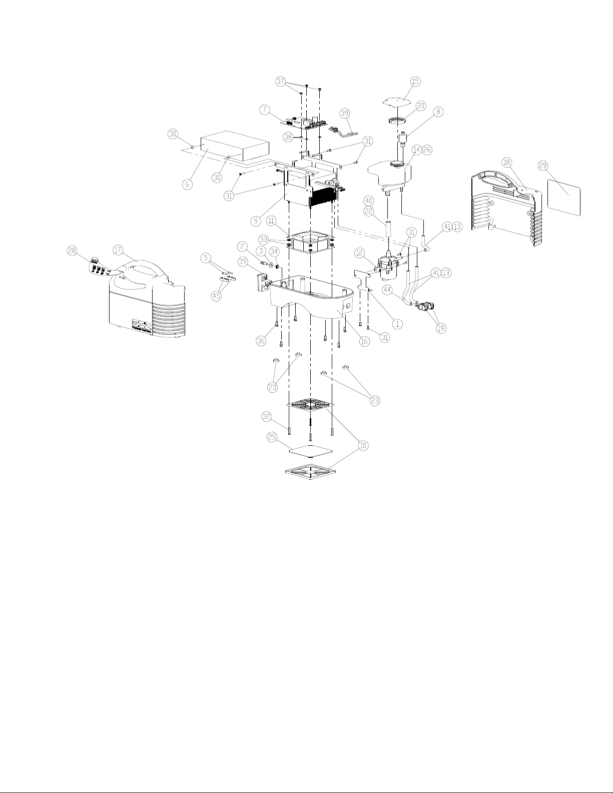
Figure 9.1: Exploded View
Page 21 of 27
Page 22
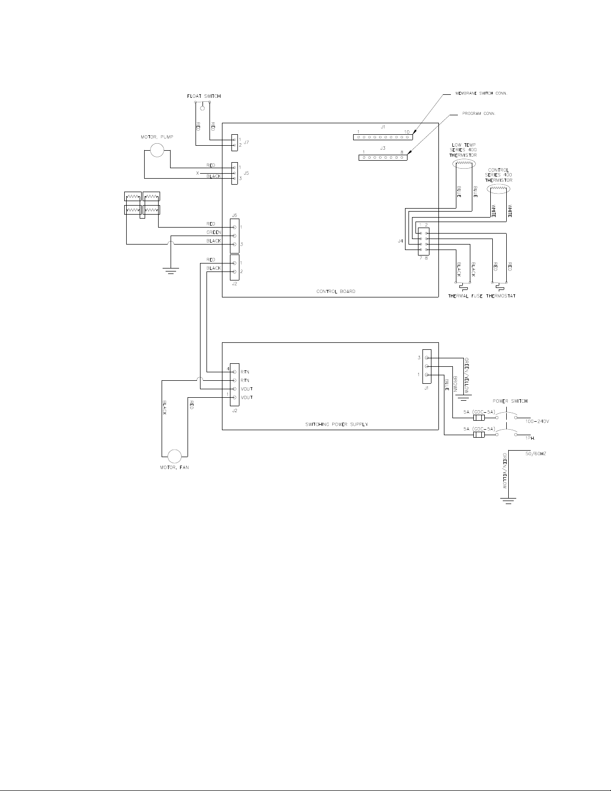
Figure 9.1: Wiring Schematic
Page 22 of 27
Page 23

11.0 FLUID CIRCUIT DISINFECTION/DRY STORAGE PROCEDURE
for Circulating Water Units Utilizing Airkem
A-33
The following procedure disinfects the fluid circuit in these products. If the product is to be placed back into
service, stop after step #5. For protracted storage in a dry state, complete the procedure. The required
tools/supplies are appropriate drain hose(s) and/or hose connector(s), a source of compressed air/nitrogen,
Airkem
A-33
Disinfectant Packets, distilled water, and the appropriate AC electrical power.
1.
Prepare distilled water/ A-33 solution in the volume needed to fill the unit’s reservoir(s). Solution must be in
the ratio of one packet of A-33 per gallon of distilled water. Set aside for later use.
2.
Turn unit OFF.
3.
Drain the water from the reservoir as described in the Operation Manual for the unit.
4.
Flush unit:
a). Fill the reservoir with solution prepared in step #1.
b). Turn unit ON, set to 5°C - 7°C (40°F- 45°F), and circulate for 5 minutes.
c). Drain unit as instructed in the Technical Manual for the unit.
d). Repeat steps 4.a - c. 3 times.
5.
If unit is to be returned to service, replenish reservoir(s) with the appropriate volume of distilled water.
6.
If unit is being placed in dry storage, continue with procedure.
7.
When all fluid has been removed from the unit, disconnect the drain hose(s) and wipe unit clean.
8.
Unit is now ready for storage.
When you are ready to return unit to service, replenish the reservoir(s) with distilled water. Perform all the checks
as described in the respective Operation and Technical Manual.
Airkem and A-33 are registered trademarks of Ecolab Inc.
Page 23 of 27
Page 24

(OPTIONAL METHOD)
FLUID CIRCUIT DISINFECTION/DRY STORAGE PROCEDURE
(for Circulating Water Units Utilizing Household Bleach (Sodium Hypochlorite)
The following procedure disinfects the fluid circuit in these products. If the product is to be placed back into
service, stop after step #8. For protracted storage in a dry state, complete the procedure. The required
tools/supplies are appropriate drain hose(s) and/or connector(s), a source of compressed air/nitrogen, a supply of
household bleach (sodium hypochlorite), Fac-Chek pH strips, distilled water, and the appropriate AC electrical
power.
1.
Turn unit OFF.
2.
Drain the water from the reservoir as described in the Technical Manual for the unit.
3.
Flush unit:
a).
Prepare a 9:1 solution of water and sodium hypochlorite (9 parts water and 1 part sodium
hypochlorite). Fill reservoir with solution.
b).
Turn unit ON, set to 5°C - 7°C (40°F- 45°F), and circulate for 5 minutes;
c).
Drain unit as instructed in the Operation Manual for the unit.
d).
Repeat steps 3.a - c. 3 times.
4.
Rinse unit three (3) times as described in Steps 3 a-c above, using distilled water only.
5.
Fill reservoir(s) with distilled water and circulate.
6.
Check the water with Fac-Chek pH strips or other appropriate method for detecting bleach. If bleach is
detected, repeat steps 5 and 6.
7.
When you no longer detect any bleach, drain reservoir.
8.
If unit is to be returned to service, replenish reservoir(s) with the appropriate volume of distilled water.
If unit is being placed in dry storage, continue with procedure.
9.
Re-connect the drain hose and drain all the fluid from the unit as in step #3 above, leaving drain hose
attached.
10.
When all fluid has been removed from the unit, disconnect the drain hose(s) and wipe unit clean.
11.
Unit is now ready for storage.
When you are ready to return unit to service, replenish their reservoir(s) with distilled water. Perform all the
checks as described in the respective Operation Manual.
Page 24 of 27
Page 25
SUGGESTIONS FOR PROTECTING THE RESERVOIR FROM BACTERIA
If sterile water is used and changed monthly, there should be no problem with bacteria forming in the reservoir or
blanket(s). If hospital procedures require the use of a bacteriostatic or bactericidal agent, we suggest HospitalApproved Bactericidal Agents which are non-acidic and non-foaming.
NOTE: Do not use De-Ionized or Reverse Osmosis Processed Water. The majority of de-ionizers do not maintain
a neutral pH of 7. If the de-ionized water is acidic, it will cause a battery effect and the copper
refrigeration line will begin to deteriorate and cause a leak in the refrigeration system.
SUGGESTED DECONTAMINATION GUIDELINES FOR
CINCINNATI SUB-ZERO EQUIPMENT
(Developed in conjunction with the risk management department at the Shriners Burn Institute in Cincinnati, Ohio)
Decontamination in the Healthcare environment is of the utmost concern with today's array of potential infectious
diseases. Cincinnati Sub-Zero has always been aware of these concerns in conjunction with the water reservoirs and
circulatory systems of CSZ equipment. For this reason, all CSZ equipment have a suggested monthly schedule for
flushing and cleaning the water system in an effort to inhibit the growth of bacteria and fungi.
The following decontamination procedure was developed to effectively rid the water system of all bacteria and not
damage any of the internal components of the equipment. All Steps should be followed as closely as possible.
This decontamination procedure should be conducted every three (3) months.
The Procedure:
1. Drain the water reservoir of your CSZ unit as described in Operational Manual
2. Flush the unit three (3) times per the following procedure.
A. Add one (1) ounce (30 cc) of household bleach (sodium hypochlorite) to the empty water
reservoir.
CAUTION
It is strongly suggested that appropriate eye protection and gloves be worn when handling and using
bleach. Wearing an apron is also suggested to protect clothing.
B. Fill the reservoir with warm tap water.
C. Turn the unit on and circulate per the chart below.
UNIT MODE TEMPERATURE DURATION
Electri-Cool II Cooling 5-7°C (40-45°F) 5 Min.
D. Drain the unit after each flush.
3. Rinse the unit three (3) times as described in (2) except to omit the household bleach (sodium
hypochlorite).
4. After the third rinse, drain the unit and add 22 ounces (650 liter) of distilled water to the water
reservoir and circulate.
5. Check the water with "Fac-Chek" pH strips or other appropriate test method for detecting bleach. If
bleach is detected, repeat steps 2 B, C, and D.
Page 25 of 27
Page 26

6. Once no bleach is detected, add the appropriate amount of U.S.P. Grade Propylene Glycol to the
water reservoir per the following chart:
UNIT U.S.P. GRADE PROPYLENE GLYCOL PER UNIT
Electri-Cool II 1.5 ounces (45 cc)
7. Continue to fill the water reservoir with distilled water.
8. Document the maintenance of the unit.
9. The unit is now ready to be placed back in service.
Page 26 of 27
Page 27

11.0 Customer Service & Support
516.536.26
To obtain parts or additional information regarding your unit, write or phone:
MAIL: Cincinnati Sub-Zero Products, Inc. Phone: 513-772-8810 / 1-800-989- 7373
12011 Mosteller Road
Cincinnati, OH 45241-1528
Attn: Customer Service
Authorized European Representative
CEpartner4U Phone: + 31 (0) 6-
Esdoorlaan 13, 3951 DB Maarn.
The Netherlands
The following information is necessary to ensure prompt service:
Model Number
Serial Number
Description of Part
Part Number (If known)
Quantity Desired
Shipping Address
Shipping Means (If any)
We strongly recommend that all repairs be done by properly trained staff.
CSZ will make available on request information which will assist the user's qualified service personnel to repair
those parts of the equipment which are designated by the manufacturer as repairable.
To qualify for credit, warranty parts must be tagged with the following information:
1. The invoice number under which the unit/part was purchased.
2. Cause of failure.
3. Serial Number of Unit.
4. Date of installation or purchase.
5. *RMA Number.
* You must first obtain an RMA number by calling CSZ Customer Service prior to returning an item.
Page 27 of 27
 Loading...