

Page 1
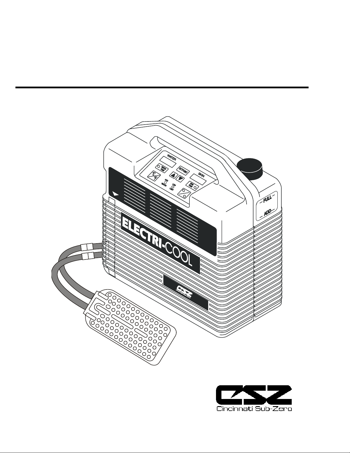
ELECTRI−COOL
Localized Cold Therapy Unit
Product Manual
®
Model 757
Page 2

LIMITED ONE YEAR WARRANTY
SCOPE OF WARRANTY
Cincinnati Sub-Zero Products, Inc. warrants the Electri-Cool
one year from date of purchase. During the warranty period Cincinnati Sub-Zero will repair or
replace, at its option, any Product which is defective in materials or workmanship or which fails to
meet the published product specification for that model. This Limited Warranty is made only to
the original purchaser of the Product and is non-transferable. The remedies described in this
Limited Warranty are the exclusive remedies for breach of warranty. THIS WARRANTY SHALL
NOT APPLY TO ANY PRODUCT WHICH HAS BEEN ALTERED OR MODIFIED IN ANY WAY
OR WHICH HAS BEEN SUBJECTED TO MISUSE OR ABUSE.
DISCLAIMER OF IMPLIED WARRANTIES
The foregoing Express Limited Warranty is given in lieu of any and all other express or implied
warranties.
CINCINNATI SUB-ZERO MAKES NO OTHER WARRANTIES INCLUDING THE IMPLIED
WARRANTIES OF MERCHANTABILITY OR FITNESS FOR A PARTICULAR PURPOSE.
LIMITATION OF REMEDIES
In no case shall Cincinnati Sub-Zero Products, Inc. be liable for any special, incidental or
consequential damages whether based on breach of warranty or other legal theory. Some states
do not allow limitations on warranties or on remedies for breach in certain transactions. In such
states, the limits in this paragraph and the preceding paragraph do not apply.
WARRANTY CLAIMS
In the event of a warranty claim within the warranty period please take the following steps:
1. Notify the Cincinnati Sub-Zero Products, Inc. Customer Service Department at Toll Free:
1-800-989-7373 or contact your local Cincinnati Sub-Zero representative. Please provide
details about the nature of the problem and include the product serial number. Upon receipt
of this information, Cincinnati Sub-Zero will provide you with a date for service or a return
shipping authorization.
2. Upon receipt of the shipping authorization, forward the equipment, freight prepaid, to the
location
specified in the shipping authorization.
Your compliance with these steps will help assure that you receive prompt warranty service for
your Product.
® Localized Cold Therapy Unit for
Manual 71065 Rev. B
DRAFT
Page 3

ELECTRI-COOL Localized Cold Therapy Unit
TABLE OF CONTENTS
1. Introduction.................................................
1.1 Purpose .....................................................................2
1.2 Indications—Localized Cold Therapy
Equipment ................................................................. 2
1.3 Contraindications......................................................2
2. Description................................................... 3
2.1 Description.................................................................3
2.2 Accessories.................................................................3
2.3 Incoming Inspection..................................................4
3. Operation..................................................... 6
3.1 Theory of Operation ................................................. 6
3.2 Safety Precautions.....................................................6
3.3 Filling Instructions.................................................... 7
3.4 Pad Connecting Instructions.................................... 7
3.5 Remote Probe Connection........................................ 7
3.6 Power Connection ..................................................... 7
3.7 Start-Up ..................................................................... 7
3.8 Mode of Operation ................................................... 8
3.9 Setpoint ...................................................................... 8
3.10 Continuous/Alternating Mode ................................. 8
3.11 Add Water ................................................................. 8
3.12 Cleaning..................................................................... 8
3.13 Storage ....................................................................... 8
3.14 Draining..................................................................... 8
4. Specifications............................................... 9
5. General Maintenance & Checkout
Proc. ............................................................
5.1 General.....................................................................10
5.2 Preventive Maintenance ......................................... 10
5.3 Checkout Procedures.............................................. 10
5.4 Calibration...............................................................11
6. Component Removal and
Replacement ...............................................
6.1 General.....................................................................12
6.2 Front to Rear Enclosure.........................................12
6.3 Vertical Power Supply Board ................................12
2
6.4 CPU Board...............................................................12
6.5 Fan............................................................................ 12
6.6 Control Panel...........................................................13
6.7 Pump Removal ........................................................13
6.8 Reservoir Removal..................................................13
6.9 Thermoelectric Unit Removal................................13
7. Troubleshooting Guide..............................
7.1 General.....................................................................14
8. Service and Parts Information .................
8.1 Warranty and Repair Policy..................................15
8.2 Obtaining Return Authorization ...........................15
8.3 Obtaining Replacement Parts ................................15
8.4 Parts List..................................................................16
9. Recommended Spare Parts.......................28
Figures
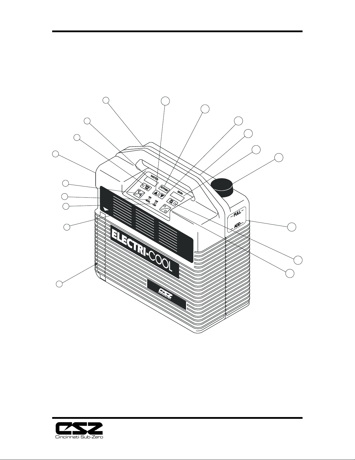
Fig. 2.1 Indicators and Switches........................................5
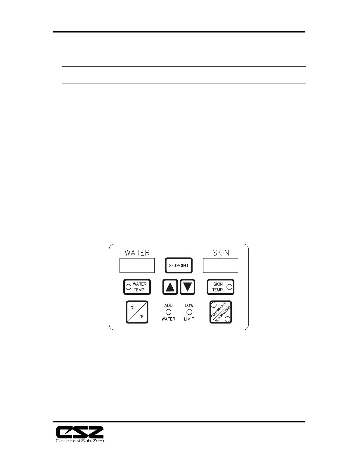
Fig. 3.1 Control Panel.........................................................6
Fig. 5.1 Temperature/Flow Tester ..................................10
Fig. 6.1 Extraction Procedure..........................................13
Fig. 6.2 4-Pin Connector ..................................................13
Fig. 6.3 9-Pin Connector ..................................................13
Fig. 8.1 Front to Rear Assembly......................................18
Fig. 8.2 Rear Assembly.....................................................19
10
Fig. 8.3 Front Assembly w/ Power Supply
(100V & 230V) .........................................................................20
Fig. 8.4 Front Assembly w/ Power Supply
(110V) 21
Fig. 8.5 Front Assembly w/ CPU Board..........................22
Fig. 8.6 Thermoelectric Unit Assembly ..........................23
Fig. 8.7 Pump Assembly...................................................24
Fig. 8.8 Reservoir Assembly ............................................25
12
Fig. 8.9 Switch Plate Assembly........................................26
Fig. 9.0 Electrical Schematic ...........................................27
14
15
1
Page 4

ELECTRI-COOL Localized Cold Therapy Unit
1. Introduction
1.1 Purpose
The purpose of this manual is to provide operation, maintenance, repair, and service
instructions for the Electri-Cool Localized Cold Therapy Unit.
1.2 Indications—Localized Cold Therapy Equipment
Cold therapy has been found to be clinically effective in accelerating the healing of
damaged tissue, and in retarding metabolism within the tissue cells.
Localized cold therapy is used in the operating room, recovery room, intensive care
unit, physical therapy, and in individual patient rooms. It is used effectively to treat
surgical incisions, as well as wounds and inflammation caused by traumatic injury. It
is prescribed with many types of surgery, for example:
• Orthopaedic (Arthroscopy, Anterior Cruciate Ligament Repair, Arthroplasty for
Hip, Knee, and other Total Joint Replacement)
• Neurologic/Orthopaedic (Laminectomy)
• Abdominal (Hernia, Cholecystectomy)
• Oral/Maxillofacial/Plastic (Dental Extractions, Rhinoplasty, Augmentations, Face
Lifts)
• Urological (Vasectomy, Prostatectomy, Urological Implants)
• Obstetrical/Gynecological (“C” Section, Episiotomy, Hysterectomy)
In most cases, cold therapy is applied immediately following the surgical procedure
directly to the wound site. This acts to reduce swelling and pain, while also reducing
or eliminating the need for pain-killing medications. For the specialty of hand
surgery, cold therapy is also applied to the upper extremity before and during the
procedure in conjunction with a tourniquet.
Other conditions indicating the application of cold therapy are:
• Acute injuries • Chronic pain
• Alopecia • Low back pain
• Arthritis • Muscle spasms
• Bruises/contusions • Sprains
• Cellulitis • Strains
1.3 Contraindications
Observe patient's skin condition frequently due to individual differences in
sensitivity and susceptibility to injury from cold or heat and/or externally applied
chemicals or pressure. Patients at greatest risk are those unconscious,
on prolonged therapy, diabetics, children, and persons incapacitated or with
insensitive skin or compromised
circulation.
2
Page 5

ELECTRI-COOL Localized Cold Therapy Unit
2. Description
2.1 Description
The Electri-Cool Unit consists of a plastic reservoir for holding distilled water; a float switch to
sense water level; a pump for circulating water through an external pad; a thermoelectric
assembly to cool the water; a microprocessor-based electronic control to regulate water
temperature and a fan to transfer absorbed heat to the ambient air.
A phone jack labeled “SKIN PROBE” allows connection of a 400 Series patient
temperature probe for monitoring and/or controlling patient skin temperature. The
control panel offers two modes of operation: “WATER TEMP” or “SKIN
TEMP”.
• In the “WATER TEMP” mode, the operator selects the desired water
temperature setpoint and the unit maintains the water at this
temperature.
• In the “SKIN TEMP” mode, the operator selects the desired skin temperature,
as measured by the remote probe, and the unit automatically lowers the
water temperature to maintain the skin temperature at the
setpoint.
• In the “WATER TEMP” mode the setpoint range is 40° to 68°F (4° to 20°C)
and in the “SKIN TEMP” mode the setpoint range is 50° to 86°F (10°
to 30°C).
Audible and visible alarms indicate “ADD WATER” and “LOW LIMIT”. Digital
displays indicate actual water temperature and skin temperature (when a probe is
connected) in degrees Fahrenheit or Celsius.
2.2 Accessories
The essential accessories for the Electri-Cool Unit are the Temp-Pad® or Maxi-
®
Therm
Lite Thermal Pads , Temp-Hose® Connection Hose, Steri-Probe® skin
probe and reusable cable.
The Thermal Pads consist of two layers of plastic sealed together to provide
multiple passageways for water flow in a random-flow pattern designed to
prevent occlusion.
Temp-Pad Localized Cold Therapy Pads
Urethane with Foam Backing Sterile w/o Straps Sterile
w/Straps
3" x 18" (7.6cm x 45.7cm) 318-US
5" x 10" (1 2.7cm x 25.4cm) 510-US 510USS
7" x 16" (1 7.8cm x 40.6cm) 716-US
8" x 14" (20.3cm x 35.6cm) 814-US 814USS
3
Page 6

ELECTRI-COOL Localized Cold Therapy Unit
11" x 12" (27.9cm x 30.5cm) 1112-US 1112USS
12" x 15" (30.5cm x 38.1 cm) 1215-US
Maxi-Therm Lite Localized Temperature Therapy Pads
EVA with Non-Woven Backing, Not Sterile
25" x 4" (63.5cm x 10.2cm) 870
22" x 16" (55.9cm x 40.6cm) 871
25" x 19" (63.5cm x 48.3cm) 872
18" x 12.5" (45.7cm x 31.8cm) 873
COOLTEMP Localized Cold Therapy Pads
Urethane with Foam Backing, Sterile
3" x 20" (7.6cm x 50.8cm) CT-60
5" x 10" (12.7cm x 25.4cm) CT-50
5" x 10" (1 2.7cm x 25.4cm) CT-50SS (self-sealing couplings)
11" x 10" (27.9cm x 25.4cm) CT-99
12" x 18" (30.5cm x 45.7cm) CT-216
ImmobilICE Supports consist of a Temp-Pad P ad contained within a
polypropylene felt body, brushed nylon outer laminate and Tietex 100% polyester
with hook and loop closures.
ImmobilICE Supports, Sterile
Universal Back Support 814-IMB
Universal Hip Support 814-IMH
Temp-Pad Wraps
Shoulder Wrap - small/medium 707-WSS
Shoulder Wrap - large/x-large 707-WSL
Knee Wrap 707-WKN
Temperature Probes
Reusable Cable 4900B
Steri-Probe, Sterile disposable Skin Probe 499B
The pads are connected to the unit via a hose with self-sealing “quick-connect”
couplings containing automatic shut-off valves at each end.
Temp-Hose
Insulated Connecting Hose, 6' (1.83m) 757-HIN
Insulated Dual Pad Connecting Hose, 8' (2.44m) 757-H8D
Other Accessories
Bed Bracket 757-BBK
Disposable Filter 757-FIL
Mobile Stand (Requires 757-BBK) 757-MST
4
Page 7
ELECTRI-COOL Localized Cold Therapy Unit
2.3 Incoming Inspection
Shipping cartons should be inspected upon receipt. If goods are damaged from
shipping, make a claim immediately to the carrier.
9
10
11
8
7
6
5
4
3
2
1
12
13
14
15
16
17
18
5
Page 8
ELECTRI-COOL Localized Cold Therapy Unit
3. Operation
CAUTION: Federal (USA) Law restricts this device to sale by or on
the order of a physician.
3.1 Theory of Operation
The Electri-Cool Unit provides a flow of temperature-controlled water to
an external pad. The unit, therefore, provides a means of cooling a
localized area of the body.
Two modes of operation are available to the operator: “WATER TEMP”
and “SKIN TEMP”. (See Fig. 3.1, Electri-Cool Control Panel.)
• In the “WATER TEMP” mode, the operator selects the desired water
temperature and sets the “SETPOINT” accordingly. The Electri-Cool
System then provides water at the “SETPOINT” temperature. To cause
a change in pad temperature, the operator must change the water
temperature setpoint.
• In the “SKIN TEMP” mode the operator selects the desired skin
temperature and sets the “SETPOINT” accordingly. The unit then
automatically provides water at a temperature necessary to maintain
the desired skin temperature.
Fig. 3.1 - Control Panel
Note: The “SKIN TEMP” mode requires the connection of a remote patient
temperature probe to sense skin temperature. If the probe becomes
disconnected, opened or shorted, an error code (“EEP”) will show in the
“SKIN TEMP” display and an audible alarm will sound.
Protection against overcooling is provided by a programmed low limit which
activates at 36°-38°F (2°- 3°C) and automatically disconnects power to the
thermoelectric unit and pump motor. In addition, if the water in the reservoir reaches
6
Page 9

ELECTRI-COOL Localized Cold Therapy Unit
a low level, an alarm alerts the operator and power is removed from the pump and
thermoelectric unit. All alarms are indicated by visual and/or audible signals.
3.2 Safety Precautions
The Electri-Cool Localized Cold Therapy Unit has been designed to provide
maximum thermal transfer efficiency at optimum safety. Safety features include:
• Microprocessor control to ensure accuracy of temperature settings at all times by
eliminating the need for
calibration.
• Digital display of actual water temperature, setpoint temperature, and skin temperature (when a
probe is attached).
• Audible and visual alarms to indicate activation of programmed low limit at 36°38°F (2°- 3°C) (power to the cooling unit and pump motor automatically
disconnected)
• Audible and visual alarms to indicate disconnected, open or shorted temperature
probe.
• Audible and visual alarms to indicate a low water level in the reservoir (power to
thermoelectric unit and pump motor automatically disconnected).
CAUTION: Read the “Operation” portion of this manual before using
product. Water or skin temperature must be set as prescribed by
physician. Observe patient’s skin condition frequently due to
individual differences in sensitivity and susceptibility to injury from
cold and/or externally applied chemicals or pressure. Patients at
greatest risk are those unconscious, on prolonged therapy, diabetics,
children, and persons incapacitated or with insensitive skin areas or
compromised circulation.
DANGER: Risk of explosion if used in the presence of flammable anesthetics.
CAUTION: Electric shock hazard. Do not remove cover. Service to be
performed by qualified service personnel only.
3.3 Filling Instructions
Remove reservoir cap and fill reservoir to full mark with distilled water only. Replace
cap.
3.4 Pad Connecting Instructions
Attach pad connecting hose to unit by inserting male couplings on 6 foot (1.83 meter) connecting
hose into female couplings on unit. Be sure couplings are locked together tightly. (An audible “click”
can be heard when couplings lock together.)
Select a CSZ Thermal Pad and insert the male couplings from the pad into the female
couplings on the hose. Again, make sure couplings are locked together tightly. The
hose and pad must be free of kinks that might restrict flow. Place or wrap pad onto
the area of the patient to be treated.
7
Page 10

ELECTRI-COOL Localized Cold Therapy Unit
3.5 Remote Probe Connection
Place a skin temperature probe onto the patient as instructed by the attending
physician. Connect the probe to the reusable cable and then insert the plug end of the
cable into the jack on the side of the unit marked “Skin Probe”.
Note: Use only 400 series patient temperature probes.
3.6 Power Connection
3.6.1 Plug the power cord into a receptacle providing the appropriate voltage for your
unit. The Electri-Cool System is now ready to begin operation.
CAUTION: Minimum clearance of 2 inches (5 cm) air space must be
maintained on left and right sides of unit where cooling slots are
located. Restriction of air flow will reduce cooling performance and
cause unit to overheat.
3.7 Start-Up
Turning the power switch to the “On” position causes the following:
• Power switch illuminates and fan energizes.
• All visual indicators flash four times.
• The audible alarm sounds.
• The setpoint and mode of operation to which the unit was last set flashes four
times.
The purpose of this “test” sequence is to allow the operator to check for proper
operation of all indicators. The operator should make sure that all indicators are
operating each time the unit is turned on. If an indicator does not illuminate, remove
unit from service and repair.
3.8 Mode of Operation
Select the mode of operation desired by pressing the “WATER TEMP” or “SKIN
TEMP” switch on the control panel. The unit will always begin operation in the
mode to which it was last set, even if it has been unplugged. An amber indicator will
illuminate adjacent to the pressed switch indicating the mode of operation chosen. If
the “SKIN TEMP” mode is selected without a probe connected, the “SKIN TEMP”
readout will display an error code, indicating “EEP”, and the audible alarm will
sound.
3.9 Setpoint
Once the mode of operation has been selected, the setpoint may be raised or lowered.
To change the setpoint, press the “SETPOINT” switch (the display will flash) and
simultaneously press either the increment (up arrow) or decrement (down arrow)
switch. The “arrow” switches can only be activated while pressing the “SETPOINT”
switch. The “SETPOINT” temperature of the mode selected will display in the
respective window of that mode. Each time the unit is turned on, the setpoint will be
the temperature at which it was last set. Therefore, power interruptions will not affect
setpoint. The setpoint range is 40° to 68°F (4° to 20°C) in the “WATER TEMP”
mode, and 50° to 86°F (10° to 30°C) in the “SKIN TEMP” mode.
8
Page 11

ELECTRI-COOL Localized Cold Therapy Unit
3.10 Continuous/Alternating Mode
The “CONTINUOUS/ALTERNATING" Mode allows for selection of either
continuous delivery of cold therapy or alternating cold therapy, i.e., the unit cycles
cooling on for 30 minutes and cooling off for 15 minutes.
3.11 Add Water
The “ADD WATER” indicator illuminates and the audible alarm sounds when the
water falls to a low level. Power to the cooling unit and pump is automatically
disconnected.
3.12 Cleaning
The Electri-Cool Localized Cold Therapy Unit case is constructed of plastic. Wipe
outer surface with a cloth soaked in a solution of water and mild detergent. Rinse
cloth of excess solution before applying to unit.
3.13 Storage
The Electri-Cool Unit may be stored full of water for short-term storage of one week
or less. If long-term storage is contemplated, it is best to drain the unit.
3.14 Draining
Drain the Electri-Cool Unit by removing the fill cap and inverting the unit over a
sink.
9
Page 12
ELECTRI-COOL Localized Cold Therapy Unit
4. Specifications
ELECTRI-COOL UNIT
Physical
Size 12.25in.W x 13.25in. H x 6.375in. D
(31.1 cm W x 33.7 cm H x 16.2 cm D)
Weight (Dry) 26 lbs. (11.79 Kg)
Hose 6 ft. (1.8 m), Insulated
Couplings Quick-Connect
Case Material Off-White Plastic
Control System
Type Microprocessor-based, Digital
Display Resolution ±1°
Self-Calibrating 60 Second Intervals
TEMP. Displays 7 Segment, 3 Digits
Display Range (Water) 32° to 122°F (0° to 50°C)
Display Range (Patient) 32° to 122°F (0° to 50°C)
Cooling System
Setpoint Range (Water) 40° to 68°F (4° to 20°C)
Setpoint Range (Patient) 50° to 86°F (10° to 30°C)
Cooling Unit Solid State, Thermoelectric
Modules
Circulating System
Reservoir Capacity 23 oz. (680 ml)
Reservoir Fluid Distilled Water
Fill Cap Vented
Flow Rate 10-13 gph (37.8-49.2 lph)
Maximum Pressure 2.5 PSI (175.76 g/cm2)
Safety System
Low Limit Alarm 36°-38°F (2°-3°C)
Add Water Alarm Removes power from pump
and cooling unit
Warning Lights ADD WATER and LOW
LIMIT
Audible Alarms ADD WATER and LOW
LIMIT; Selection of SKIN
TEMP mode without a probe
connected; Malfunction of the
water temperature sensor.
Specifications subject to change without notice
Electrical System
110-120V Unit
Voltage 110-120V, 60 Hz
Current 5 AMP (at 115V, 60 Hz)
Circuit Breaker 7 AMP
Power Cord 3 Conductor, 16 AWG, 12ft. (3.66 m)
long with Hospital Grade Plug
Leakage Current Under 300 Microamperes
220-240V Unit
10
Page 13
ELECTRI-COOL Localized Cold Therapy Unit
Voltage 220-240V, 50Hz
Current 3.0 AMP
Fuse 3.15 AMP
Leakage Current Under 500 Microamperes
100V Unit
Voltage 100 V, 50/60 Hz
Current 4.5 AMP
Circuit Breaker 7 AMP
Power Cord 3 Conductor, 16 AWG, 12ft. (3.66 m)
long with Hospital Grade Plug
Leakage Current Under 300 Microamperes
Steri-Probe
Type Thermistor, 400 Series,
Skin Sensor, Sterile Disposable
Accuracy ±.2°C at 37°C
Temp-Probe Cable 12ft. (3.66 m)
Bed Bracket 757-BBK
Bed Bracket Steel, Powder Coated with vinyl
coated hangers
Dimensions 12in. W x 11.5in. H x 8.5in. D
(30.5 cm W x 29.2 cm H x 21.6 cm D)
Temp-Stand
Material Steel, Powder-Coated
Casters (5) 4in. diameter (10.2 cm)
Dimensions 41.5in. High (105.4 cm)
22in. Diameter Base (55.9 cm)
9.5in. (24.1 cm) Deep Basket
for pads, hose, and probes: cord wrap on back.
®
Sensor 499B
®
757-MST
11
Page 14
ELECTRI-COOL Localized Cold Therapy Unit
T
5. General Maintenance and Checkout Procedures
5.1 General
This section provides recommended preventive maintenance and checkout procedures
for the Electri-Cool Localized Cold Therapy Unit.
Maintenance and checkout procedures must be performed by qualified personnel,
such as a biomedical electronics technician or a clinical engineer familiar with good
practice for medical devices.
CAUTION: Repairs of CSZ equipment by unqualified persons may void the
warranty.
5.2 Preventive Maintenance
A complete check of all Electri-Cool parameters should be made on a regularly
scheduled basis. Frequency of checkout should follow your hospital’s guidelines for
this type of equipment. CSZ suggests preventive maintenance at least every three
months.
5.3 Checkout Procedures
It is suggested you perform the following procedures in their order of listing and
document the results on a Preventative Maintenance Inspection Record.
1. Exterior Physical Inspection. Look for cracked, bent, missing, or otherwise
damaged parts. Carefully inspect the power cord for cuts or exposed wire. Check
the plug for missing or bent pins.
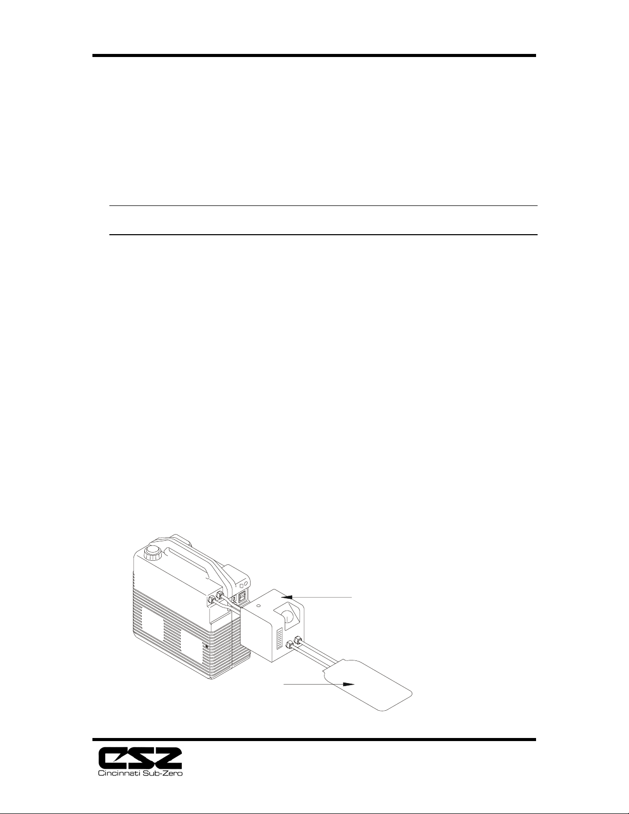
Connect the pump to the temperature/flow tester, Cat. No. 737-TFZ and a thermal
pad, as shown in Fig. 5.1. Fill the unit with distilled water and plug into a grounded
outlet providing the correct voltage and frequency. Turn unit on.
Fig. 5.1 - Temperature/Flow Tester
737-TFZ
TEMP. TESTER
NOTE: TESTER
MUST BE SET UP IN
HIS CONFIGURATION.
TEMP-PAD
®
12
Page 15

ELECTRI-COOL Localized Cold Therapy Unit
2. Flow Test. Maximum flow rate is obtained with the pad lying flat on a smooth
surface. If no flow rate is observed, check for reversed connections to pump,
kinked pad or hose, or couplings not properly seated and locked together. Check
flow rate. If less than 34 lph, check pump and/or pad for restrictions. See Trouble
Shooting Guide, Section 6.
3. Temperature Test. Take readings from the dial thermometer or add water to the
thermometer well and insert a glass or digital thermometer probe with appropriate
range such as 25° to 125°F or 0° to 50°C. Note temperature every 30 seconds for
five minutes, (ten readings). Record the average of these readings. Temperatures
should average +
refer to paragraph 5.4.
4. Add Water Switch Test. Drain the reservoir to below the “Add” mark. The
audible alarm should sound, the “ADD WATER” indicator on the front panel
should illuminate, and the pump should de-energize.
Note: To perform the next three tests, remove the filter drawer to allow access to the
fan frame.
5. Dielectric Withstand Test. Plug the Electri-Cool Cold Therapy Unit into your
Dielectric tester and turn the unit on. Attach the ground clamp to the fan frame.
The 100V and 115V units must withstand 1000V for one minute.
1°F (+1°C) of reading on digital readout. If out of calibration,
6. Ground Continuity Test. Using an ohmmeter, measure the resistance between the
fan frame and the ground pin of the power plug. This value should not exceed 0.1
ohm.
7. Leakage Current Test. Connect ground lead clamp of leakage tester to the fan
frame. Plug unit into tester. Test unit in all combinations of power switch off and
on; cooling off and on; normal and reverse polarity; and normal and open ground.
Record highest reading. If more than 300 microamperes (Refer to Trouble Shooting
Guide, Section 7. Disconnect current leakage tester set-up.
8. Low Limit Alarm Test. Add cold (below 36°F [2°C]) water to the reservoir while
the unit is running and observe the “WATER TEMP” readout. At 36°-38°F (2°3°C) the “Low Limit” indicator should illuminate and the audible alarm should
sound.
Note: It may be necessary to release some water from the pad or hose to allow the
reservoir water to enter the circulatory path.
5.4 Calibration
The Electri-Cool Localized Cold Therapy Unit contains a microprocessor-based
temperature controller. It does not require calibration and cannot be calibrated by
service personnel. The control self-calibrates every 60 seconds, effectively zeroing
out component value drifts due to aging. The unit does not compensate for calibration
variables in the temperature sensor. If the temperature readout is out of specification,
factory repair or replacement may be necessary.
13
Page 16

ELECTRI-COOL Localized Cold Therapy Unit
6. Component Removal and Replacement
6.1 General
This section provides instructions for the disassembly and removal of the major components contained
within the Electri-Cool Localized Cold Therapy Unit. Performing steps in reverse order
for reassembly also means substituting in the directions “reconnect” for
“disconnect”, “replace” for “remove”, etc. Refer to Figs. 8.1-8.9 for
component identification. Note: Make sure unit is unplugged and all necessary tools are
available before attempting any of the following procedures.
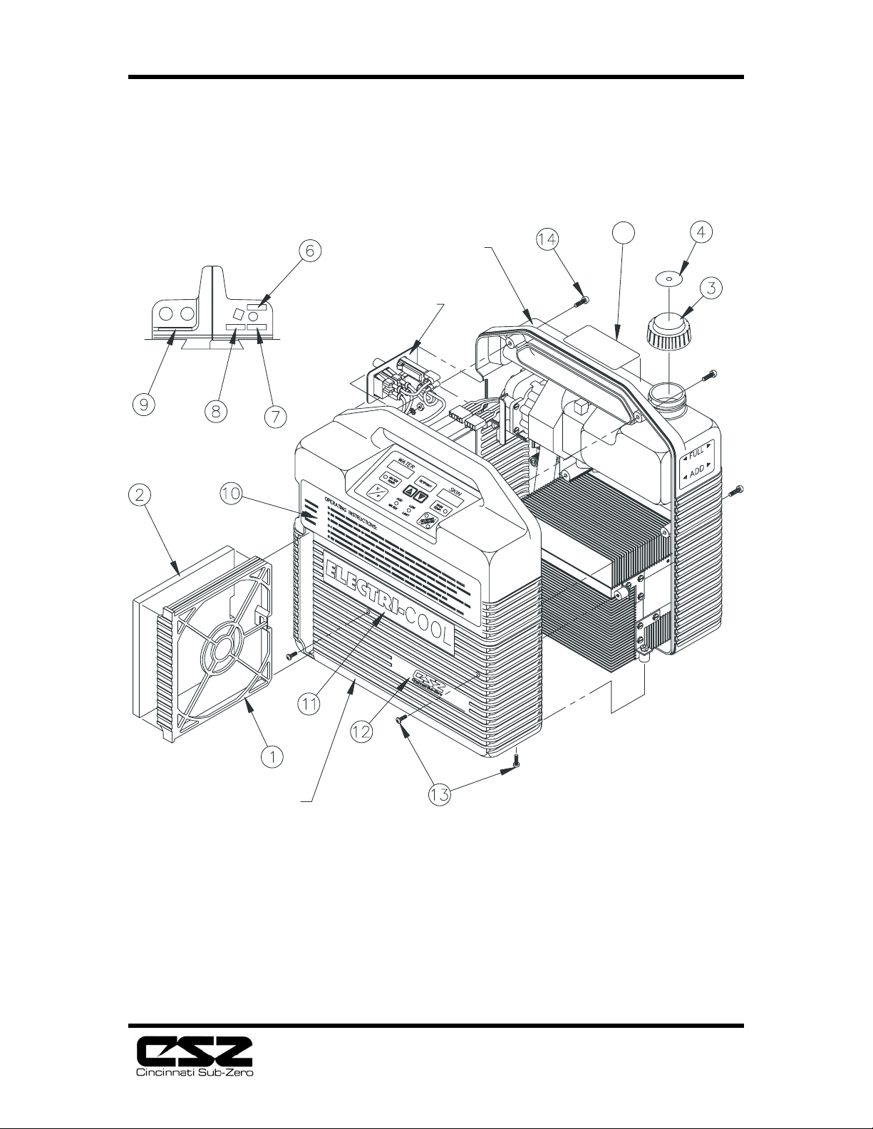
CAUTION: Working with electronic boards, plugs and cables requires
delicate handling. Proper Electro Static Discharge (ESD) handling
procedures should be followed during replacement of any electronic
board.
6.2 Front to Rear Enclosure
1. Remove drawer [1].
2. Remove four white headed screws [13] from the front enclosure. Do not remove
the white headed screws [13] from the rear enclosure.
3. Remove six recessed screws [14] from the rear enclosure.
4. Separate the two halves enough to allow access to the wiring connecting the two
halves.
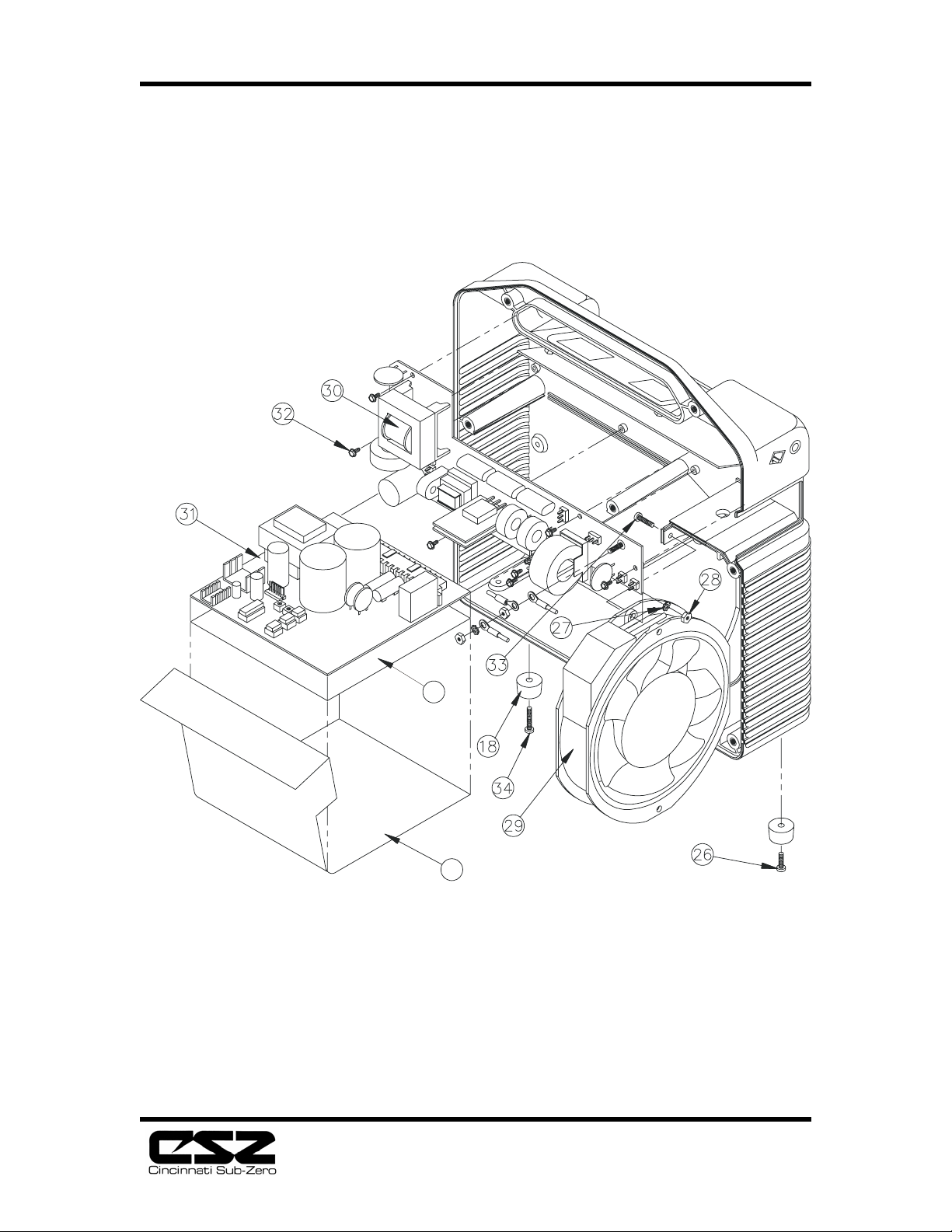
5. Disconnect the cable from the vertical power supply board [30]; disconnect the
cable from the CPU board [38].
To reassemble the two halves, perform steps 1-5 in reverse order.
6.3 Vertical Power Supply Board
1. Separate the front and rear enclosure halves. See Front to Rear Enclosure, 6.2.
2. Disconnect the fan and power wire connections from the vertical power
supply board [30].
3. Remove the 6-32 nut(s) securing the ground wires to the vertical power supply
board.
4. Remove the seven screws [32] securing the board and lift out.
To reinstall the vertical power supply board, perform steps 1-4 in reverse order.
6.4 CPU Board
1. Separate the front and rear enclosure halves. See Front to Rear Enclosure,
6.2.
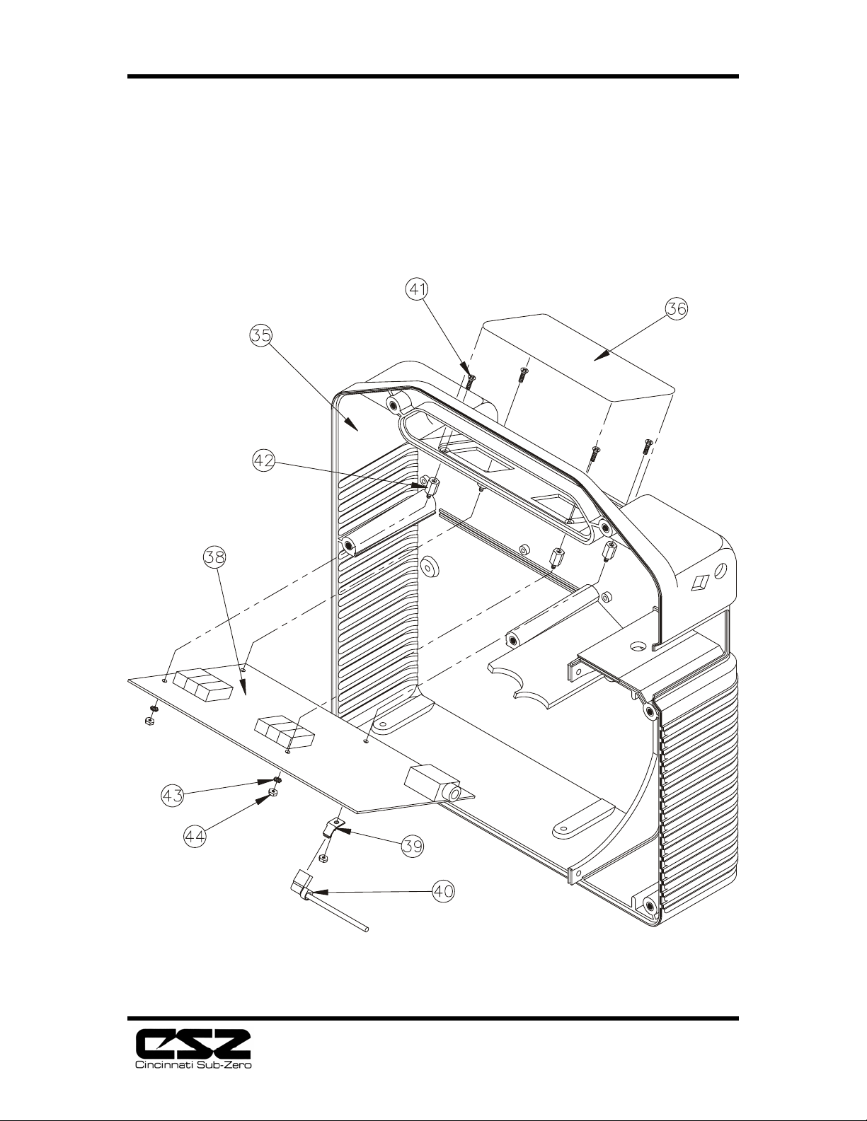
2. Disconnect the ground wire [40] from the CPU board [38].
3. Remove the four nuts [44] and three lockwashers [43] securing the CPU board
to the front enclosure. Note the orientation of item [39] for reassembly.
4. Carefully disconnect the front panel [36] connector from the CPU board.
5. Disconnect the remaining cables from the CPU board.
6. Carefully remove the CPU board from the front enclosure.
To reinstall the CPU board, perform steps 1-6 in reverse order.
14
Page 17
ELECTRI-COOL Localized Cold Therapy Unit
6.5 Fan
1. Separate the front and rear enclosure halves. See Front to Rear Enclosure,
6.2.
2. Remove the 6-32 nut securing the ground wires to the vertical power supply
board [30] and remove the fan ground wire.
3. Disconnect the fan wiring connector from the vertical power supply board
[30].
4. Remove the two screws [33] securing the fan [29] to the front enclosure.
5. Remove the fan.
To reinstall the fan, perform steps 1-5 in reverse order.
6.6 Control Panel
1. Separate the front and rear
enclosure halves. See Front to Rear
Enclosure, 6.2.
2. Remove the CPU board. See
CPU board, 6.5.
3. Remove the standoff [42]
securing the control panel ground
tail.
4. Insert a knife blade under an edge
of the control panel [36] and lift until
the panel can be grasped with
fingers. Continue to separate the
panel from the enclosure.
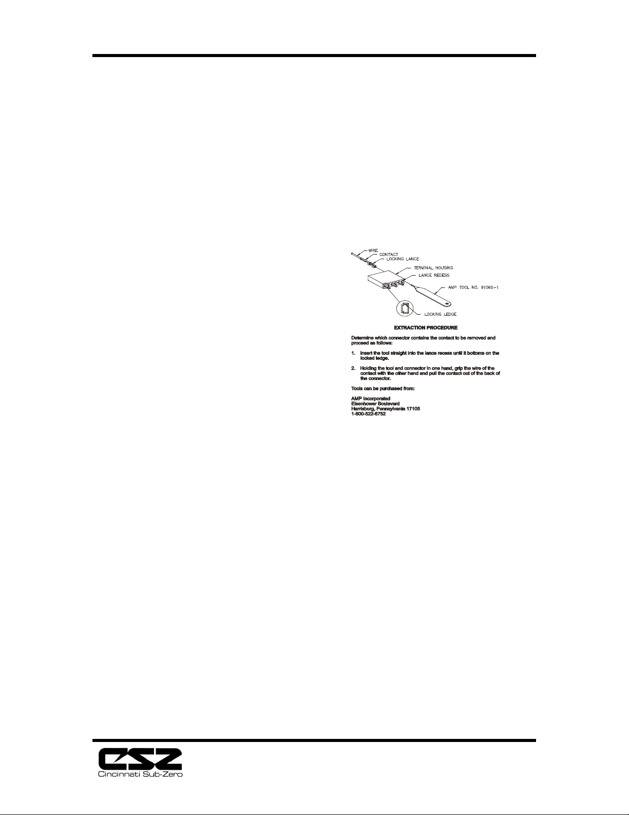
Fig. 6.1 - Extraction Procedure
To replace the control panel, remove the backing from a new panel and carefully
install on front enclosure. Perform steps 1-3 in reverse order.
6.7 Pump Removal
1. Separate the front and rear enclosures. See front and rear
enclosure, section 6.2.
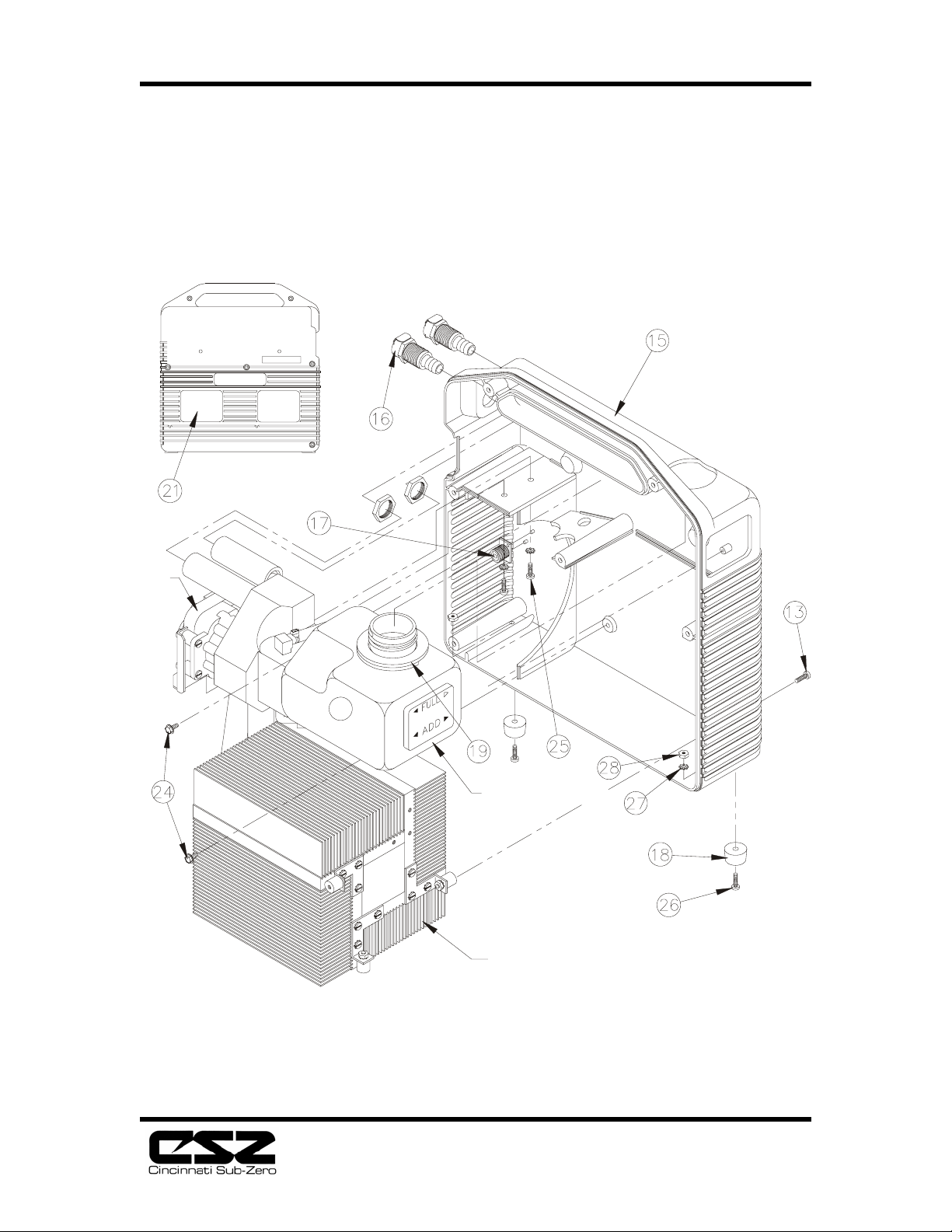
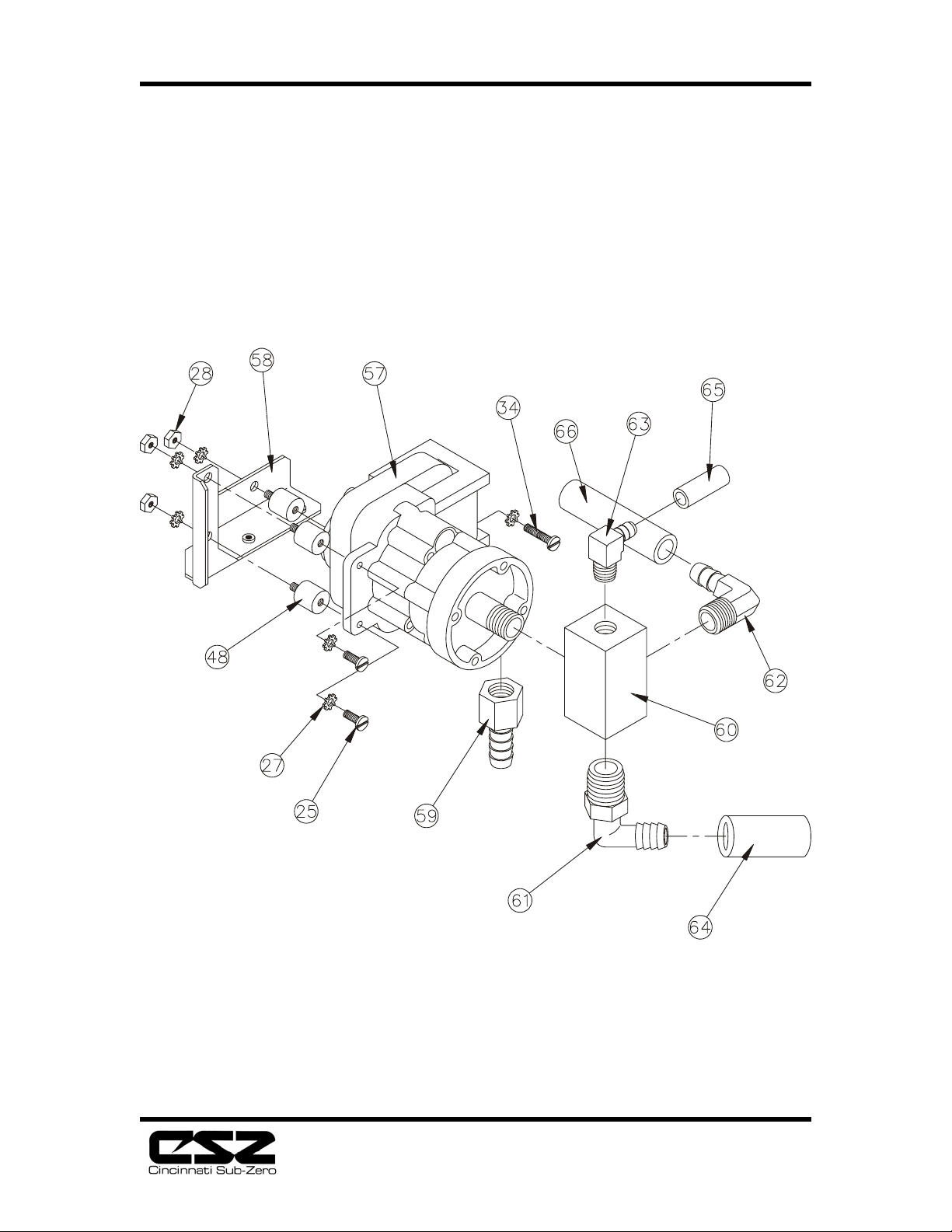
2. Remove the two screws (25) securing the pump to the rear
enclosure.
3. Separate tube (64) and tube (65) from the pump.
4. Separate tube (66) from the pump.
5. Separate the tubing from the pump to the T.E. unit.
6. Extract the pump wires from the 9-pin connector using Amp #305183 extraction
tool. See Figures 6.1 and Figure 6.3.
To reinstall the pump, perform steps 1-6 in reverse order.
15
Page 18
ELECTRI-COOL Localized Cold Therapy Unit
6.8 Reservoir Removal
1. Separate the front and rear
enclosures. See front and rear
enclosures, section 6.2.
2. Separate tube (64) and tube (65)
from reservoir.
3. Remove the two screws securing the
reservoir to the rear enclosure.
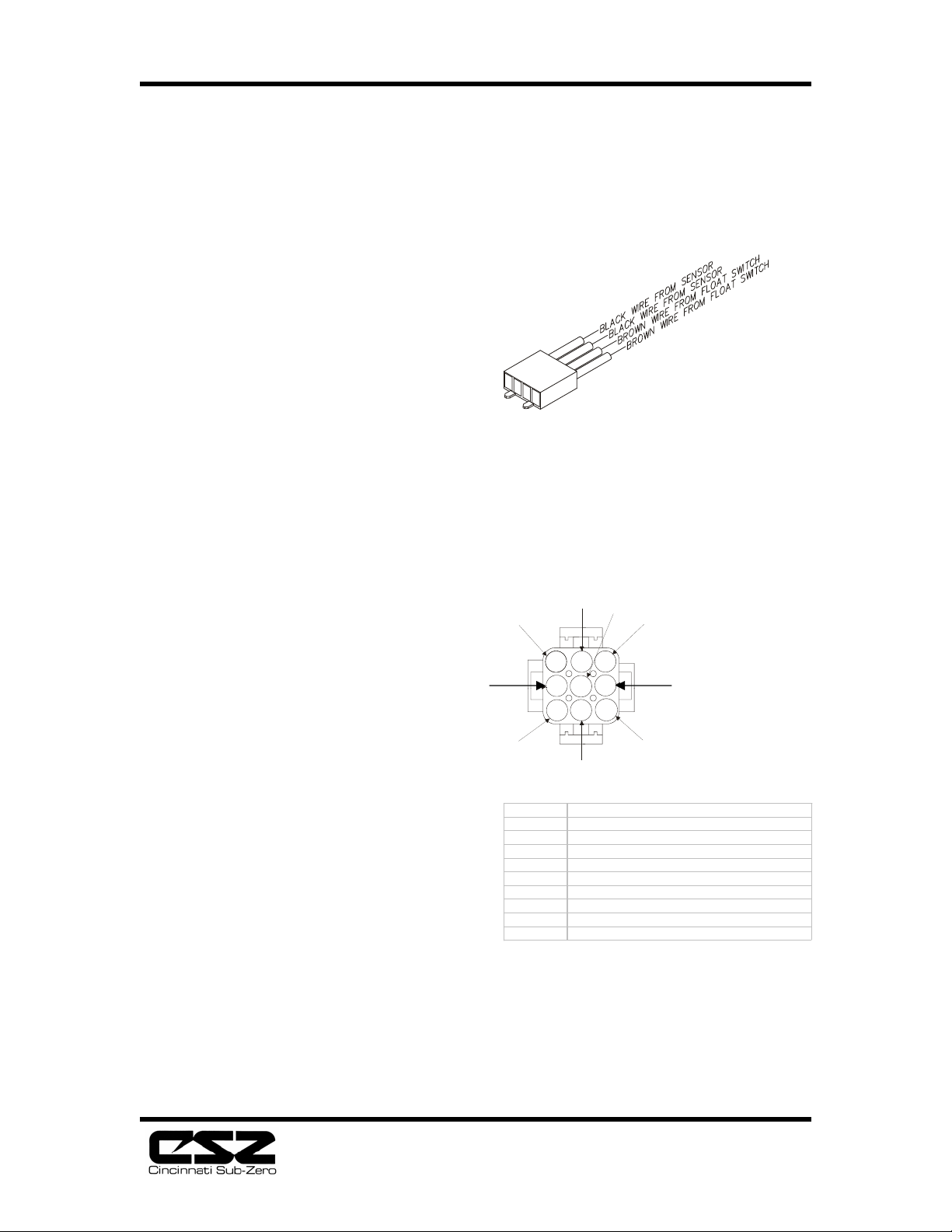
4. Extract the two brown float switch
wires from the four-pin connector
using Amp # 91065-1 extraction
tool. See Figures 6.1 and 6.2.
To reinstall the pump, perform steps 1 -4 in reverse order.
6.9 Thermoelectric Unit Removal
1. Separate the front and rear
enclosures. See front and rear
enclosures, section 6.2.
2. Remove the two screws securing the
thermoelectric unit to the rear
enclosure.
3. Extract the two black temperature
sensor wires from the four-pin
connector using Amp # 91065-1
extraction tool.
See Figures 6.1 and 6.2.
4. Extract the red, black, and ground
wires from the thermoelectric
unit at the nine-pin connector.
Also, extract the yellow and grey thermostat wires at the nine-pin connector. Use
Amp #305183 extraction tool. See Fig. 6.1 and Fig. 6.3.
5. Separate the tube connecting the thermoelectric unit to the pump.
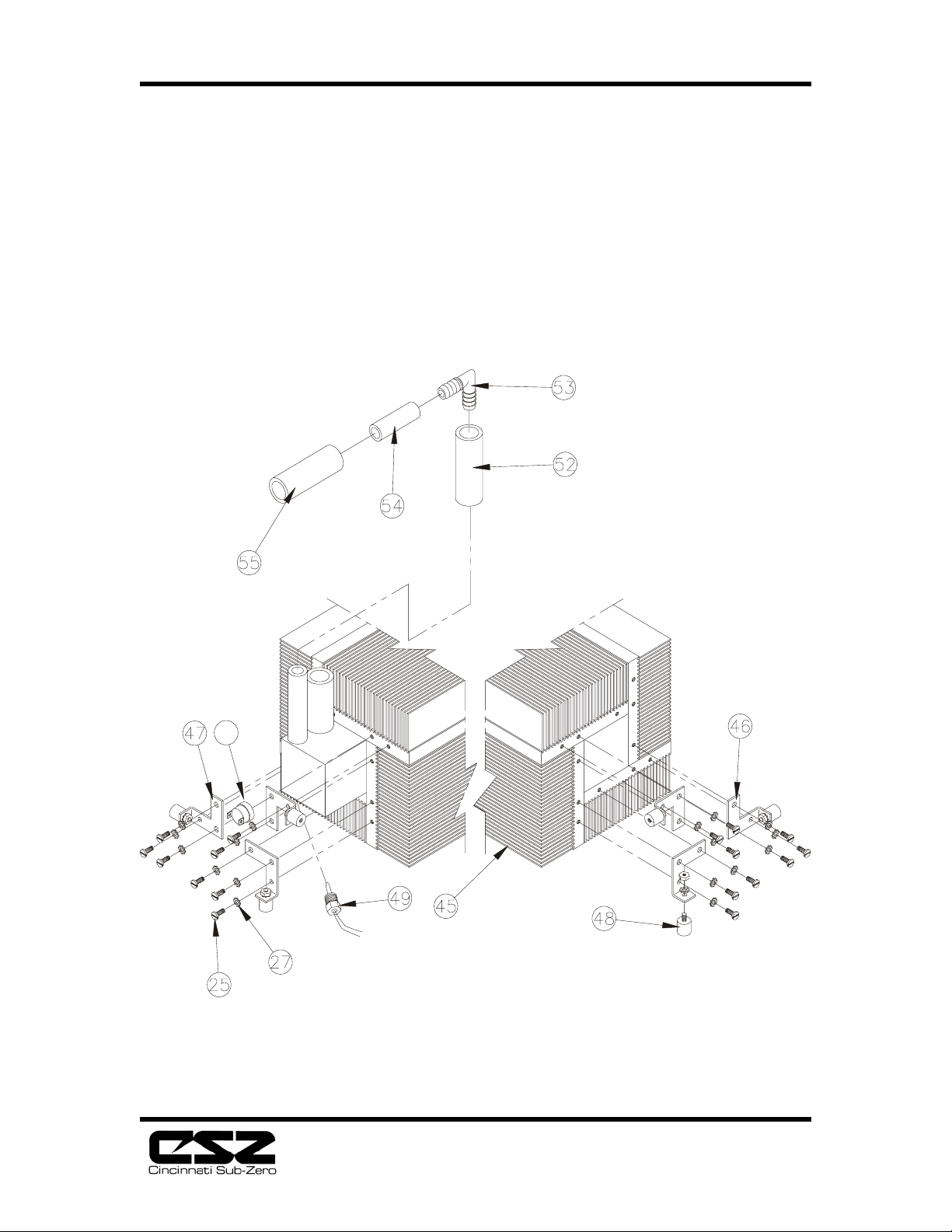
6. Separate the tube from the thermoelectric unit to the outlet coupling at the elbow (53).
To reinstall the thermoelectric unit, perform steps 1-6 in reverse order.
Fig. 6.2 - 4-Pin Connector
Fig. 6.3 - 9-Pin Connector
9
8
7
4
1BLACK FROM PUMP MOTOR
2BLACK FROM PUMP MOTOR
3 GREEN/YELLOW FROM TE UNIT
4 GRAY FROM THERMOSTAT
5 GREEN/YELLOW FROM PUMP MOTOR
6RED FROM TE UNIT
7 YELLOW FROM THERMOSTAT
8BLANK
9 BLACK F ROM TE UNIT
5
16
Page 19
ELECTRI-COOL Localized Cold Therapy Unit
7. Troubleshooting Guide
7.1 General
This section provides information to aid the service technician in diagnosing
problems with the Electri-Cool Localized Cold Therapy Unit. The left column lists
potential problems; the right column lists the most probable causes.
Problem Probable Cause
Unit will not turn on. (Power 1. Unit not plugged into proper voltage supply.
switch will not illuminate.) 2. Tripped circuit breaker (100V, 110-120V).
3. Blown fuse (220-240V).
4. Tripped mains circuit breaker.
5. Defective power cord or plug.
Displays will not illuminate. 1. Cable between power supply circuit board
and CPU board disconnected, improperly
connected, or defective.
2. Defective power supply circuit board assembly.
3. Defective CPU board assembly.
Fan(s) will not run. 1. Loose or defective connection in fan leads.
2. Defective fan.
Unit will not cool. 1. Fan filter clogged.
(No warning lights or 2. Cooling slots on either or both ends of unit
blocked.
error codes on) 3. Fan inoperative
4. Defective power supply circuit board assembly.
5. Defective CPU circuit board assembly.
6. Defective thermoelectric cooling unit.
Add Water warning alarm 1. Loose, defective, or improper connection of
will not cancel with adequate float switch leads.
water level in reservoir. 2. Defective float switch.
3. Defective CPU circuit board assembly.
4. Float stuck.
Water temperature display 1. Disconnected or defective water temperature
sensor.
indicates “EEP” 2. Water temperature below 32°F (0°C).
3. Defective CPU circuit board assembly.
Leakage current exceeds 1. Defective pump.
300 microamperes; 2. Defective fan.
17
Page 20

ELECTRI-COOL Localized Cold Therapy Unit
(500 microamperes for 3. Defective power supply circuit board assembly.
220-240V units)
18
Page 21

ELECTRI-COOL Localized Cold Therapy Unit
8. Service and Parts Information
8.1 Warranty and Repair Policy
The Electri-Cool unit is warranted against defects in material and workmanship under normal use and
operation for a period of one year. Any parts found to be defective due to improper or lack of
maintenance will be repaired or replaced at service and part rates in effect at that time. Note: After the
warranty period has expired, CSZ will repair your unit for one flat rate. Please call the CSZ Technical
Service department for further information. To qualify for credit, the warranty parts or unit must be
tagged with the following information and returned to CSZ. Extended warranty available.
1. Serial number of the unit,
2. Return Materials Authorization (RMA) number (see below),
3. Cause or nature of failure, if known,
4. Date of installation or purchase, and
5. Invoice number under which the unit or part was purchased.
8.2 Obtaining Return Material Authorization Number
Before returning any parts or units to CSZ, first obtain an RMA number from our Medical
Technical/Customer Service Department. Please carefully package all parts returned to the factory.
Please indicate RMA number on shipping label. Please follow proper ESD procedure and use non-
static shielded foam or bubble-pack to return the microprocessor control board. Shipping damage
will be the responsibility of the shipper. Insure as necessary.
8.3 Obtaining Replacement Parts
Replacement parts are available directly from CSZ. When ordering parts, specify the replacement part
number and indicate the serial number of the unit. There is NO minimum order requirement for
replacement parts. Parts are shipped F.O.B. (Cincinnati, Ohio, USA), generally within twenty-four
hours.
To obtain parts or additional information regarding your unit, write or telephone:
Cincinnati Sub-Zero Products, Inc.
12011 Mosteller Road
Cincinnati, OH 45241-1528
Telephone: 1-513-772-8810
Toll Free: 1-800-989-7373
Fax: 1-513-772-9119
We strongly recommend that all repairs be done by properly trained staff.
19
Page 22

ELECTRI-COOL Localized Cold Therapy Unit
8.4 Parts List
Item Description
1 Drawer
2 Filter
3 Cap, Reservoir
4 Label, “Use Distilled Water”
5 Label, "Alarm Conditions"
6 Label, “Skin Probe”
7 Label, “400 Series”
8 Label, “Test Probe”
9 Label, “Outlet/Return”
10 Label, Instructions
11 Label, Logo, “Electri-Cool”
12 Label, Logo, “Cincinnati Sub-Zero”
13 Screw, 6-32 1/2" Lg. White Head
14 Screw, 8-32 1/2" Lg. SS
15 Assy., Rear Enclosure
16 Coupling, Hose, Panel, 3/8in.
17 Latch, Push-To-Release
18 Foot, Mounting
19 Gasket, Fill
20
21 Label, “Hospital ID”
22
23
24 Screw, No. 6 3/8in. Lg., Hi-Lo Thd.
25 Screw, 6-32 3/8in. Lg., Pan Head
26 Screw, 6-32 1/2in. Lg., Pan Head
27 Lockwasher, #6, E t. Tooth
28 Hex Nut, 6-32
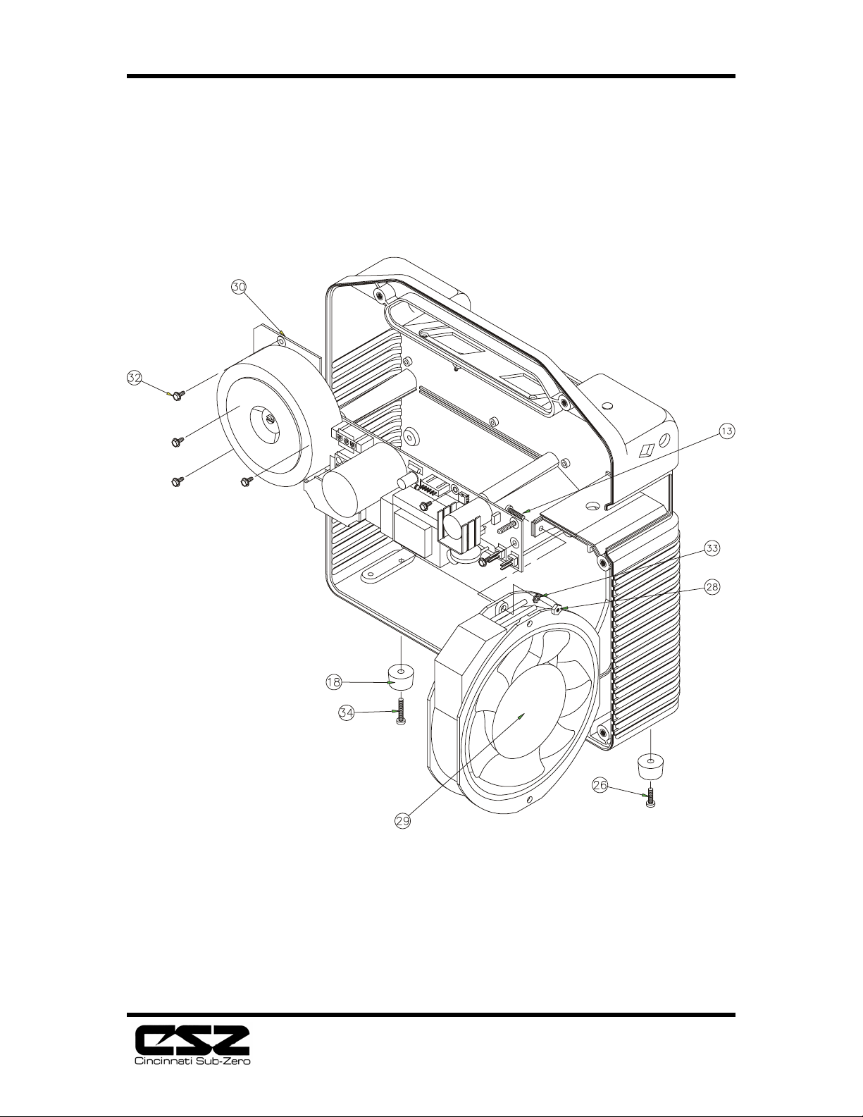
29 Assy., Fan
30 Power Supply, Vertical Board
31 Power Supply, Horizontal Board (100V and 230V
units)
32 Screw, No. 6 1/4in. Lg., Hi-Lo Thd.
33 Screw, 6-32 5/8in. Lg., Pan Head
34 Screw, 6-32 3/4in. Lg., Pan Head
35 Assy., Front Enclosure
36 Panel, Control
37
38 Control, CPU/Display Board
39 Terminal, Faston, .250
20
Page 23

ELECTRI-COOL Localized Cold Therapy Unit
40 Assy., Ground Wire
41 Screw, 4-40 3/8in. Lg., Flat Head
42 Standoff, M/F, 3/8in. Lg.
43 Lockwasher, #4, E t. Tooth
44 Hex Nut, 4-40
45 Assy.,Thermoelectric Unit
46 Bracket, TE Mount, Right Side
Item Description
47 Bracket, TE Mount, Left Side
48 Mount, Vibration Mount
49 Assy., Temperature Sensor
50 Thermostat, Backup
52 Tubing, 1/2in. Insulating Foam, 6-1/4in. Lg.
53 Elbow, 3/8in. 3/8in.
54 Tubing, 3/8in. ID 1-3/4in. Lg.
55 Tubing, 1/2in. Insulating Foam, 2-1/2in. Lg.
57 Assy., Pump
58 Bracket, Pump
59 Fitting, 1/4 FNPT 3/8 Hose
60 Block, Distribution
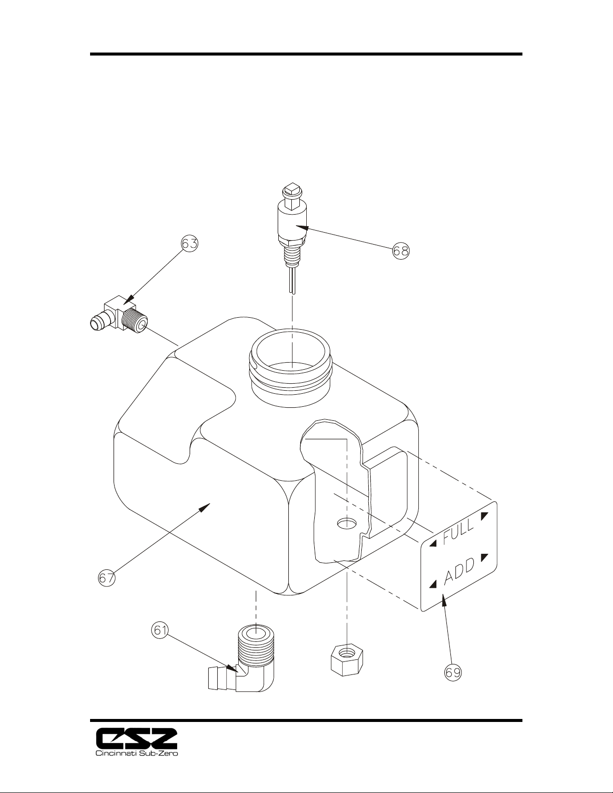
61 Elbow, 3/8 NPT 1/2 Hose
62 Elbow, 1/4 NPT 3/8 Hose
63 Elbow, 1/8 NPT 1/4 Hose
64 Tubing, 1/2in. ID 1-3/4in. Lg.
65 Tubing, 3/16in. ID 1in. Lg.
66 Tubing, 3/8in. ID 4-1/2in. Lg.
67 Reservoir
68 Assy., Float Switch
69 Label, “Full/Add”
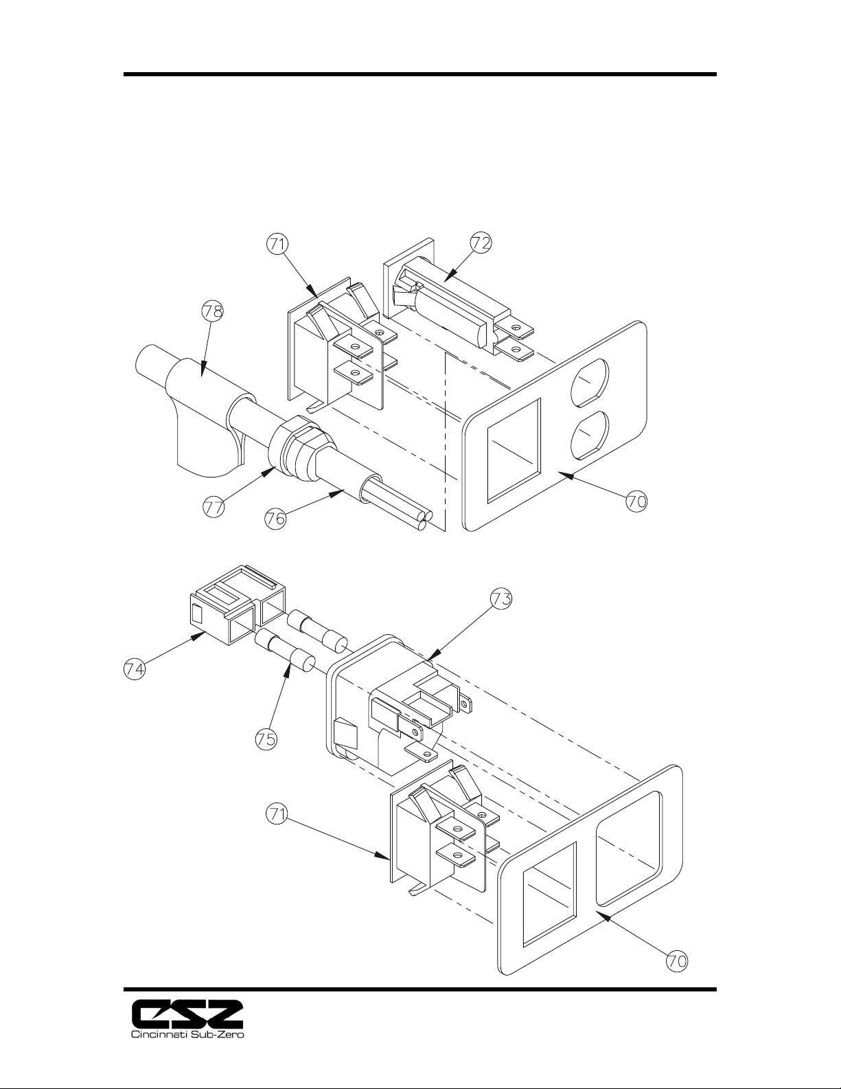
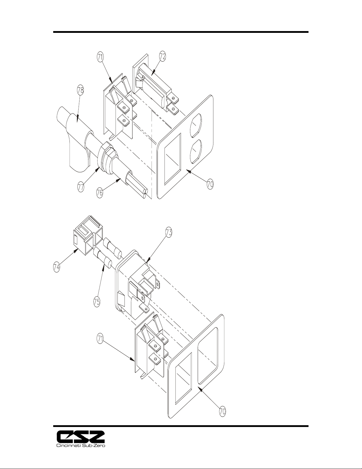
70 Plate, Switch
Plate, Switch, 230V
71 Switch, Power, DPST
Switch, Power, DPST, 230V
72 Circuit Breaker, 7 AMP
73 Receptacle, Power Inlet
74 Receptacle, Fuse Drawer
75 Fuse, 5 x 20 mm, 3.15A
76 Power Cord
21
Page 24

ELECTRI-COOL Localized Cold Therapy Unit
77 Bushing, Strain Relief
78 Cordstrap
79 Insulator, Power Supply (100V and 230V units)
80 Shield, Condensation (100V and 230V units)
22
Page 25
ELECTRI-COOL Localized Cold Therapy Unit
Fig. 8.1 Front to Rear Assembly
SEE FIG. 8.2
SEE FIG. 8.9
5
SEE FIG. 8.3
23
Page 26
ELECTRI-COOL Localized Cold Therapy Unit
Fig. 8.2 Rear AssemblyFig.
SEE
FIG.
8.7
67
SEE FIG. 8.8
SEE FIG. 8.6
24
Page 27
ELECTRI-COOL Localized Cold Therapy Unit
Fig. 8.3 Front Assembly w/ Power Supply (110V)
25
Page 28
ELECTRI-COOL Localized Cold Therapy Unit
Fig. 8.4 Front Assembly w/ Power Supply (100V & 230V)
79
80
26
Page 29
ELECTRI-COOL Localized Cold Therapy Unit
Fig. 8.5 Front Assembly w/ CPU Board
27
Page 30
ELECTRI-COOL Localized Cold Therapy Unit
Fig. 8.6 Thermoelectric Unit Assembly
50
28
Page 31
ELECTRI-COOL Localized Cold Therapy Unit
Fig. 8.7 Pump Assembly
29
Page 32
ELECTRI-COOL Localized Cold Therapy Unit
Fig. 8.8 Reservoir Assembly
30
Page 33
ELECTRI-COOL Localized Cold Therapy Unit
Fig. 8.9 Switch Plate Assembly
31
Page 34
ELECTRI-COOL Localized Cold Therapy Unit
Fig. 9.0 Electrical Schematic
32
Page 35

ELECTRI-COOL Localized Cold Therapy Unit
9. Recommended Spare Parts
I.D. No. Description
70012 Cap, Vented Screw
70114 Switch, DPST Rocker
70295 Sensor, Thermistor Temperature
70307 Coupling, Panel Hose, 3/8
70421 Foot, 3/4 Mounting
70441 Tubing, 3/8 ID x 9/16 OD
79299 Assembly, Pump
70682 Mount, Vibration Bumper
70683 Reservoir
70686 Enclosure, Front
70687 Enclosure, Rear
70688 Drawer
70693 Panel, Control
70736 CPU Board
79295 Assembly, Float Switch
70858 Thermostat, 145°F.
70884 Plug, Dome
71065 Manual, Product
71356 Gasket, Fill Opening
71903 Circuit Board, 115V
71956 Connector Plug, 9-pin
79768 T.E. Unit
70721 Filter, Disposable Air
79134 Assembly, Temperature Sensor
70735 Power Cord
±5°F
33
Page 36

Medical Division
Cincinnati Sub-Zero Products, Inc.
12011 Mosteller Road
Cincinnati, OH 45241-1528
Phone: 513-772-8810 Fax: 513-772-9119
Website: http://www.cszinc.com
E-Mail: [email protected]
 Loading...