

CSZ EZT-570S, EZT-570i Technical Manual

EZT-570S
Technical Manual
EZT570S Technical Manual RevC.doc
(450 V1.2 / 730 V1.0)

EZT-570S Technical Manual
TABLE OF CONTENTS
1. OVERVIEW ..................................................................................................... 4
1.1 Safety Information ............................................................................................................... 4
1.2 How to Use this Manual ...................................................................................................... 4
2. WHERE DO I BEGIN? .................................................................................... 5
3. RESOLVING “LOOP COMMS FAILURE” ALARMS ..................................... 7
3.1 Determining the Source of a “Loop Comms Failure” .......................................................... 7
4. CHAMBER OPERATING PROBLEMS .......................................................... 8
4.1 Conditioning System ........................................................................................................... 9
4.1.1 Temperature Limited Sheath heaters ........................................................................... 9
4.1.2 Rate Master Operation ................................................................................................. 9
4.1.3 Defrost Operation ....................................................................................................... 10
4.1.3.1 Reach-In Stability Chamber Defrost Operation ................................................. 11
4.1.4 Dual Refrigeration ....................................................................................................... 11
4.1.4.1 Alternating Defrost ............................................................................................. 12
4.1.5 Conditioning System Failures and Corrective Actions ............................................... 13
4.1.6 Conditioning System Logic Flow ................................................................................ 15
4.2 Humidity System ............................................................................................................... 18
4.2.1 Humidity System Failures and Corrective Actions ..................................................... 19
4.2.2 Humidity System Logic Flow ...................................................................................... 20
4.3 Auxiliary Cooling System .................................................................................................. 21
4.3.1 Auxiliary Cooling System Failures and Corrective Actions ........................................ 21
4.3.2 Auxiliary Cooling System Logic Flow ......................................................................... 22
4.4 Dry Air Purge System........................................................................................................ 23
4.4.1 Dry Air Purge System Failures and Corrective Actions .............................................. 23
4.4.2 Dry Air Purge System Logic Flow ............................................................................... 24
4.5 Altitude System ................................................................................................................. 25
4.5.1 Altitude System Failures and Corrective Actions ....................................................... 25
4.5.2 Altitude System Logic Flow ........................................................................................ 26
4.6 Fluid Systems .................................................................................................................... 27
4.6.1 Fluid System Failures and Corrective Actions ............................................................ 28
4.6.2 LC Fluid System Logic Flow ....................................................................................... 28
4.7 Transfer Mechanism ......................................................................................................... 29
4.7.1 Transfer Mechanism Failures and Corrective Actions ............................................... 29
4.7.2 Transfer System Logic Flow ....................................................................................... 30
5. REMOTE PC COMMUNICATION PROBLEMS ........................................... 32
5.1 Serial Communications Troubleshooting .......................................................................... 33
5.1.1 CSZ EZ-View Software ............................................................................................... 34
5.2 GPIB Communications Troubleshooting ........................................................................... 35
5.3 Ethernet Communications Troubleshooting ...................................................................... 36
6. USER INTERFACE (HMI) TROUBLESHOOTING ....................................... 37
6.1 HMI Troubleshooting and Corrective Actions ................................................................... 39
6.1.1 Factory Setup ............................................................................................................. 40
6.1.2 Touch Screen Calibration ........................................................................................... 43
7. DECIPHERING EZT INPUT/OUTPUT (I/O) OPERATION ............................ 45
2

EZT-570S Technical Manual
7.1 Standard Input Configuration ............................................................................................ 46
7.1.1 Input Description of Use .................................................................................................... 48
7.1.1.1 Custom Input Description of Use (DTS, VTS, TSB) .......................................... 53
7.1.1.2 Custom Input Description of Use (Dual Refrigeration) ...................................... 54
7.1.1.3 Custom Input Description of Use (HALT & HASS) ............................................ 58
7.1.1.4 Custom Input Description of Use (Reach-In Stability) ....................................... 59
7.1.1.5 Custom Input Description of Use (Vibration Table) ........................................... 60
7.2 Standard Output Configuration ......................................................................................... 61
7.2.1 Output Description of Use ................................................................................................. 63
7.2.1.1 Custom Output Configuration (Altitude) ............................................................ 67
7.2.1.2 Custom Output Configuration (DTS, VTS, TSB) ............................................... 68
7.2.1.3 Custom Output Configuration (Tandem/Redundant Regrigeration) .................. 69
7.2.1.4 Custom Output Configuration (HALT & HASS) ................................................. 71
7.2.1.5 Custom Output Configuration (Reach-In Stability) ............................................ 72
7.2.1.6 Custom Output Configuration (Vibration Table) ................................................ 73
7.3 Control Module Status Indicators ...................................................................................... 74
8. ADJUSTING EZT CONFIGURATION OPTIONS ......................................... 75
8.1 Accessing the EZT Configurator ....................................................................................... 75
8.2 Number of Loops/Monitors ................................................................................................ 76
8.3 Loops/Monitor Tagnames ................................................................................................. 77
8.4 Chamber Options .............................................................................................................. 79
8.5 Refrigeration Options ........................................................................................................ 82
8.5.1 Refrigeration Advanced Options ................................................................................ 84
8.6 Humidity Options ............................................................................................................... 86
8.7 Purge/Lo RH Options ........................................................................................................ 88
8.8 Auxiliary Cooling Options .................................................................................................. 89
8.9 Configuration Options ....................................................................................................... 90
8.10 CSZ Events ....................................................................................................................... 91
8.11 Critical Chamber Alarms ................................................................................................... 92
8.12 Critical Refrigeration Alarms ............................................................................................. 93
8.13 Non-Critical Alarms ........................................................................................................... 94
8.14 Maintenance Alarms ......................................................................................................... 95
8.15 Special Settings Tagnames .............................................................................................. 96
8.16 Completing EZT-570S Configuration ................................................................................ 97
Appendix
List of Figures
List of Tables
3

EZT-570S Technical Manual
1. Overview
This technical manual has been written to aid in the troubleshooting of chamber operational issues
and/or malfunctions. Note that not all options and/or features discussed in this guide may be
available or applicable to the particular chamber that is being serviced. It is highly recommended that
you read this material thoroughly prior to performing any diagnostic service in order to better assist
you in locating the section(s) that apply to your situation.
1.1 Safety Information
Note, caution and warning symbols that appear throughout this manual are to draw your attention to
important operational and safety information.
A “NOTE” marks a short message to alert you to an important detail.
A “CAUTION” safety alert appears with information that is important for protecting your
equipment and performance.
A “WARNING” safety alert appears with information that is important for protecting you,
others and equipment from damage. Pay very close attention to all warnings that apply to
your chamber.
1.2 How to Use this Manual
To start using this manual, see Section 2, Where Do I Begin? This will assist you in finding the
correct section for further information on how to diagnose and correct the problem.
Remember to keep it simple. Don’t try and solve everything at once. Take each issue one-
at-a-time. It may take several “trips” through this guide to correct each problem or locate the
root cause of a single fault, but by breaking it down into pieces you can simplify the process
and solve it in less time.
In many instances, one component failure or incorrect control setting can cause various
chamber malfunctions that would point you in several different directions, none of which may
be correct. Always try and work backwards from what is not working correctly and determine
why. Why is this not working, what makes it work and/or how should it work?
4

EZT-570S Technical Manual
2. Where Do I Begin?
The EZT570S is a Distributed Control System (DCS) that uses different hardware layers to perform
the various functions needed to operate the chamber. These include the user interface (HMI), the
control module (CM) which handles system monitoring and protection, as well as process control
(9300 or C21 controllers). This type of platform distributes the work load of controlling the chamber
into different devices and allows us to break the system down into these layers for troubleshooting
which makes diagnosing problems quicker.
Instead of looking at the system as a whole, look at each component and focus on what task it is
performing and whether or not it is doing it right. Start from the component level when tracing a
problem and work backwards from what is not working. Some problems are obvious. If I am trying to
enter a set point and the touch screen is not responding to my touch, then it is a problem with the
HMI. However, when the chamber is not doing something it is supposed to, is it the controller or
something else? Over 90% of the time it can be attributed to a wiring fault or single component
failure that prevents the system from operating. It isn’t the controller.
Example: The chamber is at 75°F and the set point is 185°F. The fans are running, but it is not
heating up. What is wrong?
Instead of approaching the problem by assuming the controller is not working correctly,
ask why is the chamber not heating up? Are the heaters on? Using the electrical
schematic for the chamber, locate the power wiring for the heater. Is there voltage to the
heaters? Is the heat output of the controller on, i.e., is the solid state relay on to supply
power to the heater. Is the heater contactor on? Is there a blown fuse?
Start from the heaters and work back. This will allow you to find what is not allowing
power to pass to the heaters. It may even be several components, like the contactor and
solid state relay, both of which get power from a common wire that may be shorted or
open due to a limit device which needs to be manually reset.
The EZT performs the same function on the chamber as any other controller. It has heat and cool
outputs for controlling temperature based on a set point. It has humidify and dehumidify outputs to
control humidity based on a set point. These outputs control the same heaters, compressors and
solenoids that any other controller would.
Since the EZT has a host of additional features and more functionality than other controllers, it is not
uncommon to look inward on the controller and blame it for any problems that arise. However,
software does not change. If it worked yesterday, then it is working today. What may not be working
is a valve that reached then end of its cycle life or a wire that has come loose or corroded to a point
where it will no longer pass power. Those types of failures are far more common.
An alarm condition may be present and not indicated on the EZT if a hardware failure or
wiring problem exists. Keep this in mind when there are no obvious fault conditions present
that would indicate why the chamber is not working properly.
In order to begin troubleshooting an issue, narrow down the search by determining which section of
this guide the problem most likely falls into based on the following information.
5

EZT-570S Technical Manual
Section 3. Resolving “Loop Comms Failure” Alarms
This section provides detailed assistance on locating and correcting serial communication problems
between the control module (CM) and 9300 loop controllers.
Section 4. Chamber Operating Problems
Use this section to diagnosis problems when no alarm messages are present. Why are the
compressors not turning on? Why is humidity not turning on when the event is on? This helps you
determine if there is a real problem or if the chamber is doing what it is supposed to.
Section 5. Remote Communication Problems
Use this section to diagnose connection problems relating to the use of the serial, Ethernet and
optional IEEE interfaces.
Section 6. User Interface (HMI) Troubleshooting
This section covers issues that may arise with the EZT display such as a non-responsive touch
screen or the EZT failing to start due to a communications failure or other hardware problems.
Section 7. Deciphering EZT Input/Output (I/O) Operation
This section reviews the functionality of the inputs and outputs of the EZT and how they are used and
controlled. This section can assist you in determining if there is a wiring or hardware problem that
may be causing the chamber to not operate properly.
Section 8. Adjusting EZT Configuration Options
This section reviews the use of the EZT’s configurator and how the settings affect the operation of the
chamber. This section is for experienced service personnel only. Changing certain settings from the
original factory settings can cause damage to equipment and/or injury to personnel. CSZ is not
responsible for damages or losses attributed to unauthorized chan ges of these settings.
This section is provided to assist with the installation of chamber options not provided originally on the
unit at the factory. Certain options, when added in the field, may require modification to specific
configurator settings in order for them to operate properly.
6

EZT-570S Technical Manual
3. Resolving “Loop Comms Failure” Alarms
The “Loop Comms Failure” alarm indicates that there is a problem with serial communications
between the control module (CM) and the 9300 or C21 loop controllers or the optional monitor input
card. The communications between the CM and the loop controllers/monitor card is performed
through the RS485 communications adapter (port 2).
When this alarm occurs, the chamber will shut down and not be able to be restarted until the alarm
condition is cleared. The cause of this alarm may lie in one of several areas. The problem could be
with the loop controller itself, the wiring between the controller and the CM or the RS485
communications adapter on the CM.
3.1 Determining the Source of a “Loop Comms Failure”
The first step in finding the cause of the communications alarm is to determine the extent of the
failure. Is it just a single loop control causing the problem or is communications down to all loop
controllers? A simple test to check for this is to change the set point of each control loop on the EZT
and verify that the set point updates on the loop control.
For example, if the air temperature set point is currently 85.0 degrees and you change the set point to
25.0 degrees, but the 9300 or C21 controlling air temperature (typically 1-INST) still has a set point of
85.0, then that may indicate the loop controller is the cause of the alarm. To verify this, perform the
same test for each control loop. If all other loop controller set points update to the new values
entered, then from this example, it can be determined that the 9300 or C21 controlling ai r temperature
is the cause of the problem.
When performing the set point change test for the humidity control loop, if the chamber is
equipped with a non temperature compensated humidity sensor, the humidity set point
entered may not match that on the loop controller depending upon the current air temperature
reading. This is due to the temperature compensation algorithm in the EZT-570S. In this
case, it is only necessary to verify that the set point changes.
When checking the product control loop, note that the product loop temperature set point will
be the same as that entered for the chamber air temperature when product control is
disabled. This allows you to check both the air temperature and product temperature control
loops at the same time with a single set point change.
If it is determined that a single 9300 or C21 is the cause of the communications failure, verify that the
rear terminal connector is seated properly on the back of the controller. If the connector is not seated
correctly, it can cause intermittent connection between the internal circuits of the controller and the
wiring terminals resulting in the communications failure. Also verify that the proper communications
settings are used. If all connections and settings appear to be correct, than replacement of the loop
controller may be necessary.
If none of the loop controller set points update when a new entry is made, then the cause of the
problem may be in the wiring or the RS485 communications adapter on the control module. Inspect
the wiring thoroughly looking for any shorts to ground or between leads. If all of the wiring appears to
be in good condition, then the last step is to replace the RS485 communications adapter on the EZT570S control module.
When replacing the communications adapter, make sure to disconnect power prior to
removing and replacing the current adapter. Failure to remove power prior to
performing the replacement procedure may cause irreparable damage to the control
module’s CPU.
7

EZT-570S Technical Manual
4. Chamber Operating Problems
This section provides direction on troubleshooting chamber operation when no alarm condition is
present. It is broken into sub-sections for temperature, humidity, altitude control, etc. Locate the
section that most closely relates to the problem at hand in order to help diagnose and solve it.
Section 4.1 Conditioning System
This section covers typical problems that may arise with the chamber’s heating and refrigeration
systems. It includes information regarding the operation of temperature limited sheath heaters for
special use as well as information on rate-master and defrost operating conditions in order to help
diagnose any problems that may occur with their operation.
Section 4.2 Humidity System
This section covers typical problems that may arise with the chamber’s humidity system. It also
includes information regarding the operation of the low RH mode (frozen coil) in order to help
diagnose any problems that may occur during operation.
Section 4.3 Auxiliary Cooling System
This section covers typical problems that may arise with the chamber’s auxiliary cooling system. It
includes information regarding the operation of both the boost cooling and cooling control modes in
order to help diagnose any problems that may occur during operatio n.
Section 4.4 Dry Air Purge System
This section covers typical problems that may arise with the chamber’s dry air purge system. It
includes information regarding the operation of the low RH mode (frozen coil) in order to help
diagnose any problems that may occur during operation.
Section 4.5 Altitude System
This section covers typical problems that may arise with the chamber’s altitude system.
Section 4.6 Fluid Systems (LC/TSB)
This section covers typical problems that may arise with the chamber’s fluid system. It also includes
information regarding hot oil heating systems for special use on explosion proof (EXP) chambers.
Section 4.7 Transfer Mechanism (DTS/VTS/TSB)
This section covers typical problems that may arise with the basket transfer mechanism. It includes
information regarding the operation for both air and motor operated system s.
8

EZT-570S Technical Manual
4.1 Conditioning System
When the main chamber event is turned on, whether it is a standard ZP, TSB or VTS for example,
temperature control is the primary function. The air circulator/bath output will turn on and enable the
heating/cooling logic. Even though the air circulator/bath output (typically Q2 or Q44) may vary based
on the type of chamber, it performs the same function.
The minimum heat/cool enable output (Q41), if equipped, turns on with the chamber event to enable
the control circuits for heating and cooling. This output is typically only used and wired into the
control circuit when the chamber is equipped with defrost. In defrost, the output would turn off in
order to disable the heating and cooling control circuits while defrost is running.
The maximum cool output (Q1) and maximum heat output (Q31) are controlled by the configurator
settings. When the cooling or heating output percent exceeds the configurator set point for the on
delay period, the maximum output will turn on. They operate as boost outputs, i.e., they are on/off
outputs, not proportioning outputs. They connect additional heating and cooling circuits to the 9300
or C21 controller outputs in order to boost chamber performance.
Heating operation is relatively basic; however, the refrigeration system operation is more complicated
with staging of compressors, etc. Depending upon options present on the chamber, it may include
the rate master refrigeration system operation and/or defrost. The sequence of operation then varies
from that of a typical chamber.
4.1.1 Temperature Limited Sheath heaters
Temperature limited sheath heaters are used in applications where there is, or may be, the presence
of a flammable substance within the chamber. These heaters operate at lower surface temperatures
than standard open element, nichrome wire heaters and their surface is not electrically “live”. This
allows a temperature sensor, typically a thermocouple, to be placed on their surface. The sensor is
then connected to a limit device.
This limit device monitors the surface temperature of the heater and removes power from the heater
when the surface temperature exceeds the maximum operating limit. The limit device overrides any
call for heating by the chamber controller. Once the temperature drops below the operating limit,
power is restored to the heaters if heating is still required. The operating temperature limit is dictated
by the flammable material. The maximum operating temperature of the heater surface can be no
higher than 80% of the auto-ignition temperature of the flammable material in degrees centigrade.
4.1.2 Rate Master Operation
The operation of the refrigeration system varies with temperature for a rate master system. When the
chamber air temperature is above the rate master lockout set point, typically -20°C (-4°F), as set in
the configurator, and the air temperature set point is at or above the switchover set point, typically
0°C (32°F), the refrigeration system operates in single stage mode. The system 1 compressor output
(Q3), solenoids output (Q30) and the rate master control output (Q40) will be on when cooling is
required.
The rate master control output is used to switch the cooling output of the 9300 or C21 loop controller
from the system 2 cooling solenoids over to the system 1 cooling solenoids. The maximum cool
output will turn on and off based on the demand for cooling as normal. The refrigeration system will
switch over to cascade mode when the air temperature drops below the switchover set point and the
air temperature set point is below the lockout set point.
During the switch from single stage to cascade mode, the cascade cooling control output (Q43) will
turn on and the maximum cooling output (Q1) will be disabled. This allows some of system 1’s
capacity to be diverted to the cascade condenser to pre-cool it prior to system 2 starting.
9
EZT-570S Technical Manual
After the stager start delay, system 2’s output (Q4) will turn on and the rate master control output
(Q40) will turn off. The cooling output of the 9300 or C21 will now be used to control system 2 cooling
solenoids. The maximum cool output (Q1) is then re-enabled so that it can turn on system 2
maximum cool solenoids if needed. For safety, when the air temperature is below the lockout set
point, the system will only start and run in cascade mode. This prevents the system 1 evaporator
from becoming a condenser (due to the lower chamber air temperature) and causing liquid slugging
of the system 1 compressor.
4.1.3 Defrost Operation
There are two base selections for defrost in the EZT’s configurator. These are regular and large
horsepower defrost. Defrost can also be configured for regular or large horsepower alternating
defrost; however, these selections are only available if the chamber is configured with redundant
refrigeration systems and independent plenums. If it is a tandem refrigeration system where both
systems work together in a combined plenum, then alternating defrost is not available.
The large horsepower selection is typically used on systems 7.5HP and larger. The difference
between the selections defines how system 1 is controlled in order to cool system 2. With standard
defrost, the system 1 compressor is cycled on and off based on system 2 head pressure. With large
horsepower defrost, system 1 compressor remains in operation while output Q43 cycles system 1
cascade cooling solenoids on and off to maintain system 2 head pressure.
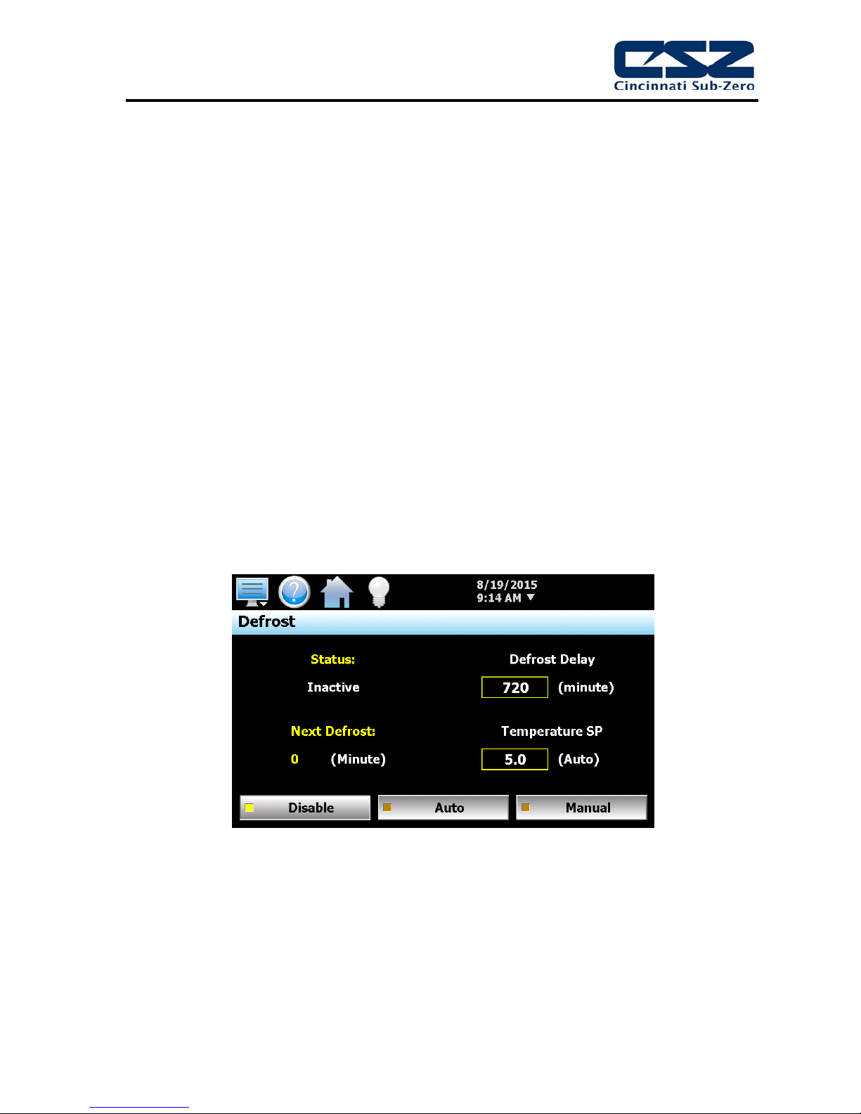
Defrost can be manually initiated by turning on the defrost event, or it can be automatically started by
the EZT based on the defrost settings. When in automatic mode, the defrost timer will begin counting
down whenever the air temperature set point is below the defrost set point. Once the timer counts
down to zero, defrost is initiated for one cycle. Upon completion of the cycle, the timer will begin the
next timed countdown.
When defrost is started, the air circulator output is turned off. The minimum heat/cool output is also
turned off. This prevents any heating or cooling from taking place. The defrost solenoid output (Q42)
will turn on and system 2 will continue operating. This supplies hot gas to the cooling coil. If defrost
is set up for regular operation, system 1 compressor will be cycled on and off to provide cooling to
system 2 based on the defrost pressure control input (I40).
If large horsepower defrost is selected, the system1 compressor will remain on, and the cascade
cooling output (Q43) will be cycled on and off to provide cooling to the cascade for system 2. This
process will continue until the defrost temperature switch input (I41) is made indicating that the
suction temperature of the coil has warmed up to the defrost temperature setting. This will initiate a
10
Figure 4-1 Defrost Settings

EZT-570S Technical Manual
15 minute timer in the EZT. Defrost will continue for another 15 minutes to insure that the coil is
completely defrosted. Once the 15 minute defrost time has elapsed, pre-chill is started.
In pre-chill, the defrost solenoid will be turned off and the minimum heating/cooling output (Q41) will
be turned on. This will allow the refrigeration system to pre cool the coil prior to starting the air
circulators. Once the defrost temperature switch turns off, indicating that the suction line has dropped
below the defrost temperature, a one minute timer begins. Once this timer is complete, pre-chill will
terminate, the air circulators will turn back on, and the system will resume normal operation.
4.1.3.1 Reach-In Stability Chamber Defrost Operation
Defrost operation on the reach-in stability series chambers is done by simply disabling the cooling
solenoid. The single stage refrigeration system of the stability series has its hot-gas bypass plumbed
directly into the evaporator. Thus, when cooling is not taking place, hot gas is flowing through the coil
which naturally defrosts the evaporator.
When defrost is activated according to the user entries on the Defrost screen, the air circulators,
humidity system, heating/cooling are disabled. The compressor will continue to operate in bypass for
a period of 15 minutes in order to defrost the evaporator. After the 15 minute defrost period, cooling
is re-enabled so that the evaporator can be pre cooled prior to the air circulators turning back on.
After a pre cool delay period of 1 minute, the chamber then returns to normal operation.
4.1.4 Dual Refrigeration
Dual refrigeration refers to two refrigeration systems working together or alternately to condition the
chamber. When the refrigeration systems are set to tandem operation, they work together. When
cooling or dehumidification is required, both systems will start and stop in unison as required based
on the cooling and/or dehumidification demand. When redundant operation is specified, only one
refrigeration system runs at a time, and the systems alternate back and forth on a duty cycle to
equalize runtime.
The first system, system ‘A’, uses the standard control outputs for system 1 and 2 compressor (Q3
and Q4). System ‘B’ compressors are assigned to outputs Q46 and Q47 for system 1 and system 2.
The EZT also uses input I31 for the system 1B pumpdown switch and Q45 for the system 1B
solenoids, which allows independent control and pumpdown of system 1B. When each system is
assigned to its own conditioning plenum, additional inputs and outputs are used to start and stop the
air circulators on plenum ‘B’ (Q44) as well as monitor for heater over temperature (I4), motor overload
(I5) and a second boiler system on the additional plenum (I30 and I46).
When independent system failure is configured, a safety trip on one system will not shut down the
other system. This allows the chamber to continue to “limp” along with only one system under
tandem operation, or to switch to the “back-up” system when operating in redundant mode. If
independent plenums are not used, the chamber would still operate if it was a refrigeration safety trip;
however, if the fault was associated with a motor overload or over temperature condition with the
chamber heaters, the chamber would shut down because both refrigeration systems share the same
plenum.
When independent control loops are specified, requiring independent conditioning plenums, the EZT
will send the same temperature and humidity set points to the 9300 or C21 controllers for each
plenum. The EZT will then average the readings together when running in tandem mode, or only
utilize the values from the operating plenum when in redundant mode.
11

EZT-570S Technical Manual
4.1.4.1 Alternating Defrost
When alternating defrost is selected for redundant refrigeration systems, and defrost has been
initiated on the currently running system, system ‘A’ for example, the EZT will start system ‘B’ prior to
starting the defrost cycle. This minimizes the change in chamber temperature by allowing system ‘B’
to begin operation first.
Once the defrost cycle has completed on system ‘A’; however, the pre-chill step will not take place.
Since system ‘B’ is currently cooling the chamber, there is no need to pre-chill the coil because
system ‘A’ not required. If for some reason system ‘B’ was faulted out and unavailable, the pre-chill
step would take place prior to restarting system ‘A’ because it is then required to cool the chamber.
Note that when defrost is in automatic mode, the EZT will not begin counting down the next defrost
cycle for system ‘B’ until defrost is complete on system ‘A’ and vice versa.
12

EZT-570S Technical Manual
4.1.5 Conditioning System Failures and Corrective Actions
SYMPTOM PROBABLE CAUSES CORRECTIVE ACTIONS
Chamber air circulator(s) not turning
on.
Chamber not heating.
System 1 compressor not turning on.
System 2 compressor not turning on.
Chamber event not turned on.
Conditioning system disabled (altitude
chambers).
Blown fuse.
Chamber in defrost (if equipped).
Basket not in correct position
(DTS/VTS).
Chamber door open (if door switch
enabled in configurator).
Chamber event not on.
Conditioning system disabled (altitude
chambers).
Blown heater fuse.
Sheath heater limit tripped.
9300/C21 controller output off.
Chamber in defrost (if equipped).
Chamber event not on.
Conditioning system disabled (altitude
chambers).
Blown fuse.
Compressor internal thermal overload
tripped.
Chamber in defrost (if equipped).
Refrigeration system not enabled or
compressor percent on set point not
exceeded for delay time.
Blown fuse.
Compressor internal thermal overload
Turn on chamber event.
Altitude above controllable limit for
temperature. Decrease altitude or
turn off altitude system.
Replace Fuse.
Check defrost status. Allow defrost to
complete or terminate defrost.
Check basket position and adjust if
necessary. Check basket position
sensors, adjust/replace.
Close chamber door.
Turn on chamber event.
Altitude above controllable limit for
temperature. Decrease altitude or
turn off altitude system.
Replace fuse.
Check heater limit. Maximum
temperature reached.
Verify proper 9300/C21 controller
configuration. Check set point.
Replace controller.
Check defrost status. Allow defrost to
complete or terminate defrost.
Turn on chamber event.
Altitude above controllable limit for
temperature. Decrease altitude or
turn off altitude system.
Replace fuse.
Allow compressor to cool. Check
refrigeration system/injection valve
operation.
Check defrost status. Allow defrost to
complete. Compressor will cycle as
needed.
Check configurator settings. Refrig
system type should match installed
system type.
Replace fuse.
Allow compressor to cool. Check
13

EZT-570S Technical Manual
SYMPTOM PROBABLE CAUSES CORRECTIVE ACTIONS
Chamber not cooling.
(further diagnosis and/or repair
requires certified refrigeration service
personnel)
Defrost not starting.
Defrost not terminating.
tripped.
Chamber in humidity mode.
Refrigeration system not enabled or
stager start delay time not met.
Chamber event not on.
Conditioning system disabled (altitude
chambers).
Cooling coil fouled with ice build-up.
9300 controller output off.
Chamber in defrost (if equipped).
Refrigeration system capacity
exceeded.
Suction line not below defrost
thermostat setting.
Defrost thermostat not working.
Defrost delay off period (15 minutes) not
completed.
Defrost thermostat not working.
refrigeration system/injection valve
operation.
Check humidity system type. System
2 disabled for single stage humidity
operation.
Check configurator settings.
Refrigeration system type should
match installed system type. Wait for
stager start delay period.
Turn on chamber event.
Altitude above controllable limit for
temperature. Decrease altitude or
turn off altitude system.
Initiate defrost or warm up chamber to
melt ice from coil. Seal ports or leaks
in chamber to minimize moisture
migration into chamber and
accumulating on coil.
Verify proper 9300 controller
configuration. Check set point.
Replace 9300 controller.
Check defrost status. Allow defrost to
complete or terminate defrost.
Reduce live load in chamber.
Check thermostat setting. Defrost not
required.
Check thermostat set point and
operation. Adjust/replace.
Allow enough time for defrost
sequence to complete.
Check thermostat set point and
operation. Adjust/replace.
14
EZT-570S Technical Manual
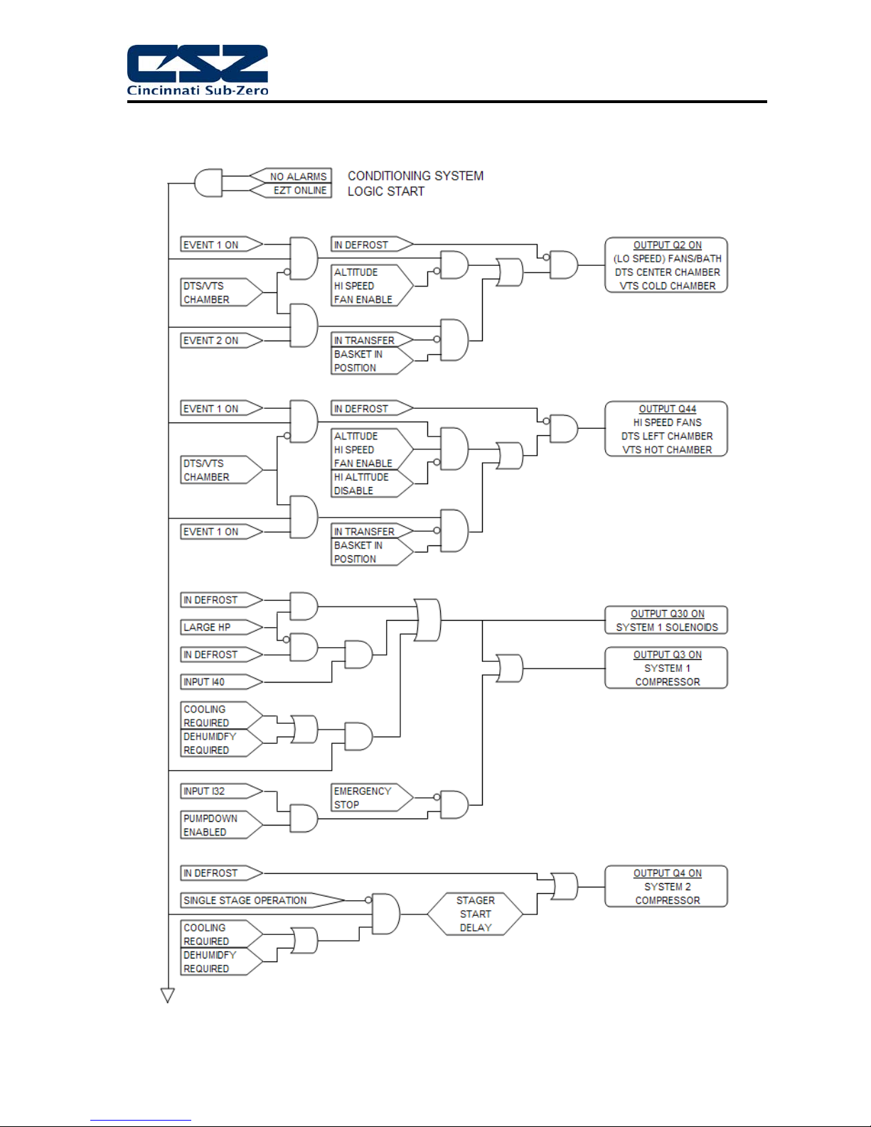
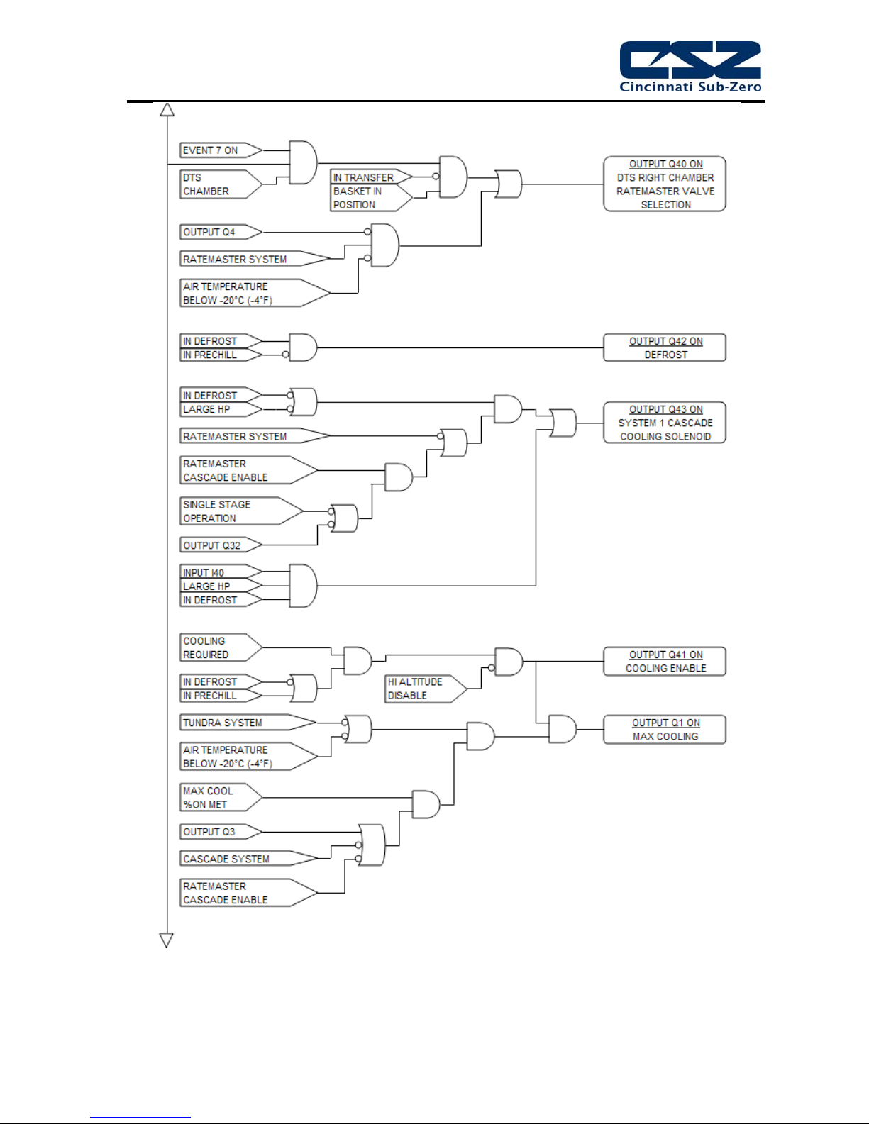
4.1.6 Conditioning System Logic Flow
15
EZT-570S Technical Manual
16

EZT-570S Technical Manual
The logic for the system ‘B’ refrigeration system is the same as that shown in the chart above
for a standard chamber with a single refrigeration system. The logic is merely duplicated and
tied to different outputs for the control of the second system.
17

EZT-570S Technical Manual
4.2 Humidity System
When the humidity system is enabled, the humidity system output (Q32) will turn on. This turns on
water supply solenoids and atomizer air compressor if applicable. If the refrigeration system is set to
run in single stage mode when humidity is on, system 2 compressor (Q4) will then be turned off as
long as humidity is on. The maximum humidify output (Q33) will turn on whenever the humidification
output percentage exceeds the set point in the configurator for the on delay time period.
An alarm delay is added to the boiler low water input (I7) in order to allow enough time for it to fill with
water when the humidity system is first turned on. The delay will prevent the alarm from going off for
a period of 30 minutes. Should the level not be made in that time, the alarm will sound and shut
down the chamber. Once the proper water level is reached, the alarm will sound and shut down the
chamber immediately upon loosing the input. Should the alarm occur, silence the alarm from the
alarm screen and the chamber will begin operating again and restart the 30 minute alarm delay timer.
Temperature Limits
The EZT limits the humidity system’s operational range to a minimum and maximum temperature as
set in the configurator. These limits are typically set around freezing and boiling temperatures. Once
the air temperature exceeds either limit, the EZT shuts down the humidity system automatically. If
the humidity system is shut down due to temperature limitations, the system status monitor will
indicate that this has occurred by illuminating the “RH TMP DISABLE” indicator. The humidity system
will restart automatically once the air temperature returns to within the set temperature range.
Dewpoint Limits
In order to protect the refrigeration system and chamber from damage, there are minimum and
maximum dewpoint levels that are set in the configurator. These limits in turn define the minimum
and maximum relative humidity levels that the chamber will operate to at any given temperature. The
EZT uses these limits and internally calculates the minimum and maximum humidity level that the
chamber will control to at the current chamber temperature.
Should the user enter a set point outside of those limits, the EZT will coerce the 9300 or C21 set point
to the minimum or maximum value allowed. The system status monitor will then indicate that limiting
is taking place and in which direction by illuminating the appropriate LED on the status monitor
screen.
Low RH (Frozen Coil)
For chambers equipped with the low RH (frozen coil) option, the EZT monitors the temperature and
relative humidity set points and calculates the resulting dewpoint. When this value is below the
standard wet coil range of ~2°C (35°F), the EZT automatically switches to frozen coil mode. This
allows the chamber to reach lower humidity levels than what is capable with standard humidity.
The EZT does not initiate frozen coil mode until the measured dewpoint in the chamber is below 10°C
(50°F). This prevents the coil from loading up with moisture prematurely and reducing the duration of
time at which the coil can affectively control low humidity levels in the chamber.
When frozen coil mode is initiated, the frozen coil control output (Q35) turns on. This activates the
EPR bypass solenoid and transfers control from the wet coil solenoid to the frozen coil solenoid to the
dehumidification output of the 9300 or C21 controller.
18

EZT-570S Technical Manual
4.2.1 Humidity System Failures and Corrective Actions
SYMPTOM PROBABLE CAUSES CORRECTIVE ACTIONS
Humidity system not turning on.
Chamber not humidifying.
Chamber not dehumidifying.
(further diagnosis and/or repair
requires certified refrigeration service
personnel)
Humidity event not turned on.
Air temperature outside of humidity
control range.
Altitude system on (altitude chambers).
Humidity not enabled in configurator.
Maximum dewpoint limit reached.
Boiler filling with water/heating up.
Blown boiler heater fuse.
9300/C21 controller output off.
Atomizer nozzle clogged.
Atomizer water supply low.
Atomizer air supply low.
Minimum dewpoint limit reached.
Dehumidification coil logged with
moisture.
9300/C21 controller output off.
Turn on humidity event.
Change temperature set point to
within allowable humidity control
range.
Turn off altitude system.
Check configurator settings.
Check system status monitor.
Chamber operating at maximum
humidity level.
Check water supply. Allow time for
boiler to heat up.
Replace fuse.
Verify proper 9300/C21 controller
configuration. Check set point.
Replace controller.
Check/clean atomizer nozzle.
Check water supply. Increase flow
rate.
Verify air compressor operation.
Check for leaks/cracks in tubing.
Check system status monitor.
Chamber operating at minimum
humidity level.
Check coil. Warm up chamber to
remove moisture build-up.
Verify proper 9300/C21 controller
configuration. Check set point.
Replace controller.
19
EZT-570S Technical Manual
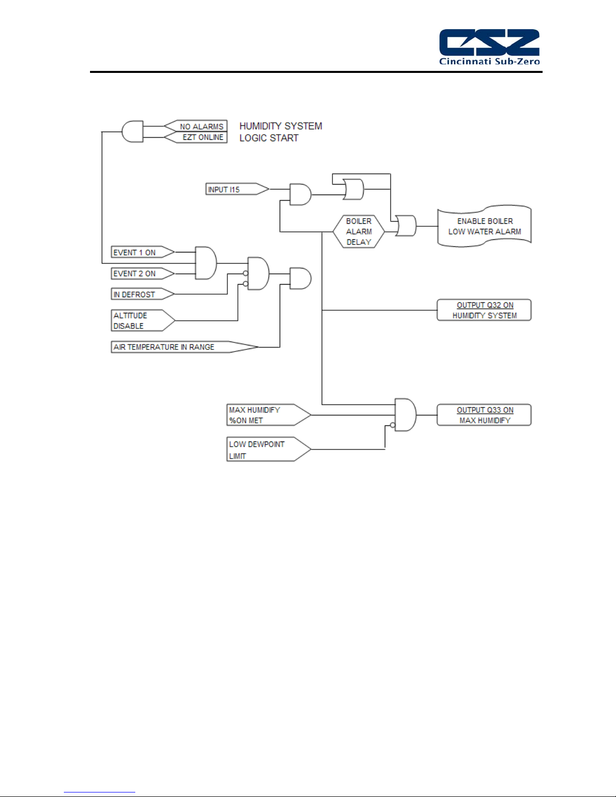
4.2.2 Humidity System Logic Flow
20

EZT-570S Technical Manual
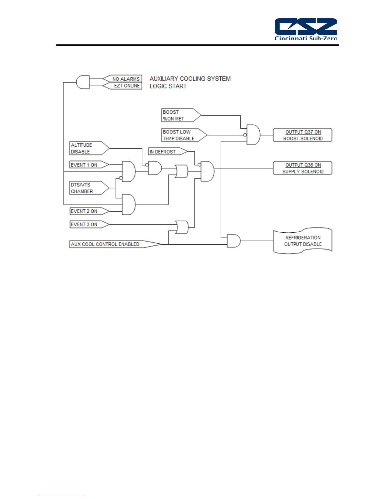
4.3 Auxiliary Cooling System
The auxiliary cooling system can be installed as a boost system or a low range control system. When
set as a boost, it will assist the refrigeration system in lowering chamber temperatures quickly. As a
control, it will take over once the low temperature limit of the refrigeration system is reached and
continue cooling the chamber down to an ultimate low of the auxiliary cooling medium (LN2 or CO2).
Auxiliary Cool Boost Operation
When the auxiliary cooling option is set for boost in the configurator, the auxiliary cooling supply valve
output (Q36) will turn on when the chamber and auxiliary cooling events are enabled. The EZT will
then monitor the cooling percentage of output. When it exceeds the auxiliary cooling on percentage
set point for the on delay time period, the boost cool output (Q37) will turn on. When the percentage
of output drops below the on percentage set point, the output will turn off. The supply valve output
will remain on as long as the event is on. Only the boost output will cycle on and off for control.
Once the air temperature reaches the low limit set point in the configurator (boost cool disable), the
boost cooling output will be disabled to prevent the chamber from going colder than what the
refrigeration system is capable of in order to protect the compressors.
Auxiliary Cool Control Operation
When auxiliary cooling is set for control in the configurator, the auxiliary cooling system will operate
according to the boost control logic until the low limit set point is reached. The low limit set point in
the configurator (boost cool disable) is the lowest safe operating range for the refrigeration system.
Once the low limit set point temperature is reached, the refrigeration system is shut down and the
minimum heat/cool output (Q41) is disabled. This transfers the cooling output from the 9300 or C21
controller to the auxiliary cooling control solenoid. This allows the chamber to be controlled to
temperatures below what the refrigeration system can produce.
4.3.1 Auxiliary Cooling System Failures and Corrective Actions
SYMPTOM PROBABLE CAUSES CORRECTIVE ACTIONS
Boost cooling not turning on.
Poor cooling performance with
auxiliary cooling on.
Auxiliary cooling event not turned on.
Loop percentage of output not
exceeding on percentage for delay
period.
Air temperature at minimum allowable
range.
Altitude system on (altitude chambers).
Cooling medium (LN2/CO2) not
reaching chamber as liquid.
Supply/control valve clogged/failed.
Turn on auxiliary cooling event.
Check loop output percentage, adjust
configurator settings if necessary for
performance.
Chamber at low limit. Can not go any
colder.
Turn off altitude system.
Allow boost cooling to run longer in
order for liquid to reach chamber.
Insulate supply lines.
Install automatic purge system to
bleed off gas in order to maintain
liquid in supply line.
Inspect valve. Clean/Replace if
necessary.
21
EZT-570S Technical Manual
4.3.2 Auxiliary Cooling System Logic Flow
22

EZT-570S Technical Manual
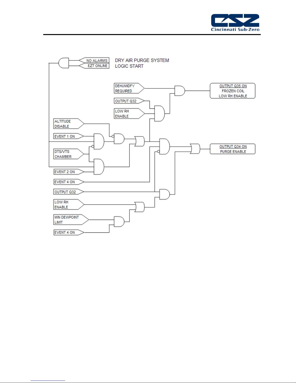
4.4 Dry Air Purge System
The dry air purge system can work independently or as part of the humidity system. If the chamber is
a standard dry unit (non humidity) or the humidity system is off, the dry air purge output (Q34) will turn
on when the chamber and purge events are turned on. The purge system will run continuously
supplying dry air to the chamber until the event is turned off.
If the chamber is equipped with humidity, the dry air purge system output (Q34) will be automatically
turned off when the humidity system is turned on. This is done in order to allow the humidity system
to control the humidity level. If the purge system was allowed to continue operation, it would be
constantly trying to dry the chamber regardless of the humidity set point. However, if the minimum
dewpoint limit is reached, the humidity system will allow the dry air purge system to operate when the
purge event is on, in order to obtain the lowest possible humidity level. The purge system will act as
the primary method of dehumidification since the wet coil is limited by the low dewpoint limit.
For chambers equipped with the low RH (frozen coil) option; the purge system will automatically run
during low RH humidity operation. The EZT monitors the temperature and relative humidity set points
and calculates the resulting dewpoint. When this value is below the standard wet coil range, the EZT
will automatically switch to frozen coil mode. The EZT does not initiate frozen coil mode until the
measured dewpoint in the chamber is below 10°C (50°F). This prevents the coil from loading up with
moisture prematurely and reducing the duration of time at which the coil can affectively control low
humidity levels in the chamber.
When frozen coil mode is initiated, the dry air purge system output (Q34) and air control solenoid
output (Q35) turn on. The air control solenoid output transfers control of the purge air supply over to
the dehumidification output of the 9300 or C21 loop controller. This allows the dry air purge to be
controlled along with the dehumidification solenoid for proper humidity control.
4.4.1 Dry Air Purge System Failures and Corrective Actions
SYMPTOM PROBABLE CAUSES CORRECTIVE ACTIONS
Purge system not supplying dry air to
chamber.
Dry air purge not turning on.
Purge system off.
No compressed air supply.
Purge flow meter adjusted too low.
Supply/control valve clogged/failed.
Purge event not turned on.
Chamber operating in humidity mode.
Altitude system on (altitude chambers).
Turn on purge event.
Supply compressed air to purge
system.
Verify/adjust flow meter for proper flow
rate.
Inspect valve. Clean/Replace if
necessary.
Turn on purge event.
Purge automatically controlled. Dry air
purge will turn on automatically when
required. Turn off humidity.
Turn off altitude.
23
EZT-570S Technical Manual
4.4.2 Dry Air Purge System Logic Flow
24

EZT-570S Technical Manual
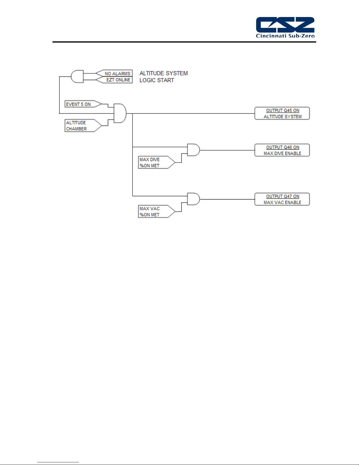
4.5 Altitude System
When the altitude system is enabled, the altitude system output (Q45) will turn on. This turns on the
vacuum pump and any isolation valves to seal the chamber. The maximum dive output (Q46) and
maximum vacuum output (Q47) are controlled by the configurator settings. When the loop output
percent exceeds the configurator set point for the on delay period, the maximum output will turn on.
They operate as boost outputs, i.e., they are on/off outputs, not proportioning outputs. They connect
additional air and vacuum supply circuits to the loop controller outputs in order to boost chamber
performance.
The altitude system automatically disables humidity, auxiliary cooling and dry air purge when it is
turned on. These systems can not run when the altitude system is on. The conditioning system is
allowed to run until the altitude reaches the conditioning system disable set point in the configurator.
Once this altitude is reached, both heating and cooling is shut down. During the allowed operating
range, the air circulator motors will switch from low speed (output Q2) to high speed (output Q44)
once the high speed fan enable set point is reached. This improves the heating and cooling
performance at higher altitudes due to the low air density in the chamber.
4.5.1 Altitude System Failures and Corrective Actions
SYMPTOM PROBABLE CAUSES CORRECTIVE ACTIONS
Chamber not increasing in altitude.
Chamber not decreasing in altitude.
Altitude turned off.
Manual dive valve open.
Vacuum pump not running.
Leak in chamber.
9300/C21 controller output off.
Vacuum control valve clogged/failed.
No compressed air supply.
9300/C21 controller output off.
Air supply control valve clogged/failed.
Turn on altitude event.
Close dive valve.
Check/replace fuse. Reset overload.
Check for leaks. Check door gaskets
and latches for tight seal.
Verify proper 9300/C21 controller
configuration. Check set point.
Replace controller.
Inspect valve. Clean/Replace if
necessary.
Check/supply chamber with
compressed air. Check pressure
regulator setting.
Verify proper 9300/C21 controller
configuration. Check set point.
Replace controller.
Inspect valve. Clean/Replace if
necessary.
25
EZT-570S Technical Manual
4.5.2 Altitude System Logic Flow
26

EZT-570S Technical Manual
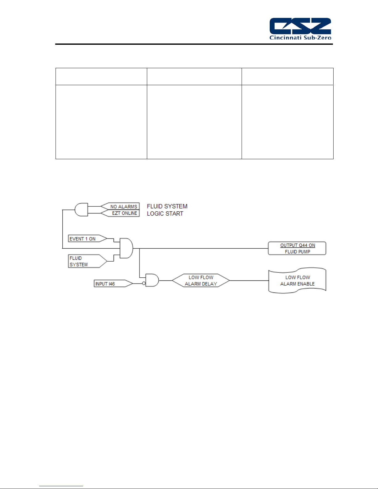
4.6 Fluid Systems
Fluid systems can vary considerably between different types of chambers. LC’s, TSB’s and explosion
proof chambers are typical candidates for fluid systems. For LC’s and TSB’s, it is the only means of
heating and cooling the product under test.
Troubleshooting fluid system problems generally ends up with a heating or cooling system diagnosis.
As long as fluid is flowing at the proper rate, temperature control falls back to the heating and cooling
systems. As long as the pump is operating properly and all isolation valves are open, there isn’t
much to consider.
LC Chambers
When the chamber event is turned on, the fluid system pump is started in order to keep fluid flowing
through the system to condition the test product. The fluid is heated and cooled as it flows through
the heater barrel and heat exchanger much like the air across the heater and evaporator in a typical
chamber.
The fluid system is equipped with safeties that insure that fluid is flowing through the system prior to
allowing heating or cooling of the fluid to commence. This protects the system and components from
damage that may occur by operating with no fluid flow. The heating and cooling outputs function in
the same manner as a standard chamber, except they are controlling fluid temperature instead of air.
TSB Chambers
When the chamber event is turned on, the fluid system pumps are started in order to keep fluid
flowing through the system to condition the test product. Some smaller TSB’s merely have mixers in
the bath to promote flow over the heaters and evaporator mounted in the baths. The fluid is heated
and cooled as it flows across the heater and heat exchanger much like the air across the heater and
evaporator in a typical chamber.
For TSB’s with fluid pumps, the fluid system is equipped with safeties that insure that fluid is flowing
through the system prior to allowing heating or cooling of the fluid to commence. This protects the
system and components from damage that may occur by operating with no fluid flow. The heating
and cooling outputs function in the same manner as a standard chamber, except they are controlling
fluid temperature instead of air.
Hot baths are typically for heating only. They do not have any means of cooling the fluid. Cold baths
may or may not have heaters in order to warm up and operate at elevated temperatures. Typically,
cold baths are for cooling only.
Explosion Proof Chambers
Division I, explosion proof chambers typically use “hot oil” systems as the means for heating the
chamber. Division I explosion proof classifications require that no component, even upon failure, can
ignite the flammable substance present. Electric heaters can short or rupture in a failure condition
thus causing an explosion. Also, the surface temperature of the heaters is critical to safety. No
portion of the heater surface can operate over 80% of the auto-ignition temperature of the flammable
material as defined by Article 500 of the NEC.
Hot oil systems are equipped with independent temperature controls. These control devices will
maintain the fluid at a preset temperature and/or prevent it from exceeding the maximum allowed
operating temperature. The chamber temperature control will then cycle solenoids to control the flow
of the fluid into a heating coil in the chamber, thus heating the air. Since the fluid is maintained at a
safe temperature, even if the coil were to rupture, there is no source of ignition present.
27
EZT-570S Technical Manual
4.6.1 Fluid System Failures and Corrective Actions
SYMPTOM PROBABLE CAUSES CORRECTIVE ACTIONS
Low or no fluid flow.
Blockage in piping/closed valves.
Pressure relief valve bypassing fluid.
Pump failure.
Blown fuse.
4.6.2 LC Fluid System Logic Flow
Locate blockage and remove/open
valves.
Check pump pressure. Adjust/replace
relief valve.
Check pump shaft coupling.
Check motor overload/reset.
Worn pump. Replace/repair.
Replace fuse.
28

EZT-570S Technical Manual
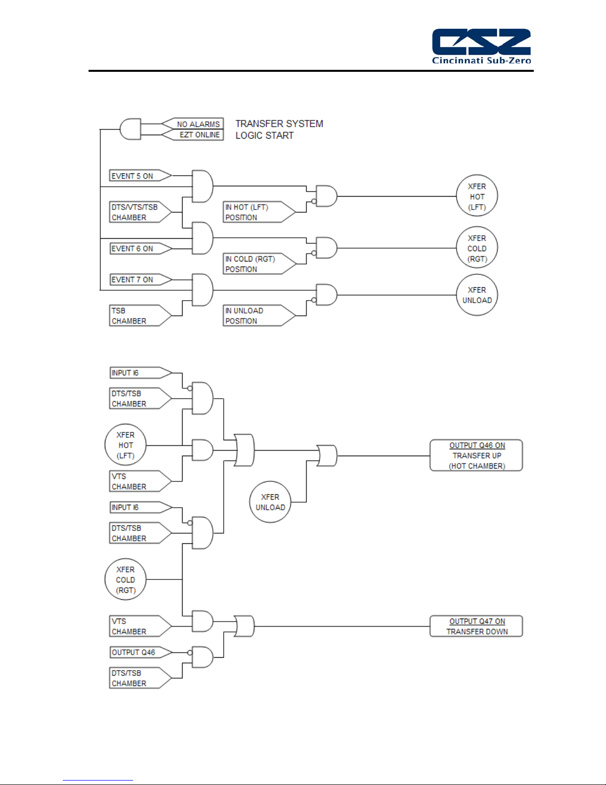
4.7 Transfer Mechanism
Transfer mechanisms are used on thermal shock chambers (DTS/VTS/TSB) to move a basket loaded
with test product from one extreme temperature to another. These systems may utilize a single motor
drive or one or more air cylinders to move the basket between the different temperature zones.
Motor Operated Transfer Mechanism
Motor operated transfer mechanisms are typically used on TSB’s. They consist of a gear-motor drive
with a lever arm attached to the output shaft. The motor direction is switched between clockwise and
counterclockwise rotation in order to move the basket back and forth between the baths.
Limit switches are used to indicate each of the three positions, hot, cold and unload. The motor
direction is determined by the current position of the basket, as indicated by which position switch is
on, and the desired bath position set by the events. The motor runs until the limit switch for the
desired position is met.
Air Cylinder Operated Mechanism
Air operated transfer mechanisms for DTS and VTS chambers are relatively simple. A single air
cylinder is used to move the basket between the two available positions. Because of the design, the
basket provides the mechanical stop for the cylinder. The cylinder continues to push on the basket,
thus sealing the gasket surface to keep the hot and cold chambers separate. Limit switches are
positioned on each end of the cylinder in order to identify the basket position.
TSB transfer mechanisms employing air cylinders are more sophisticated. They use two cylinders,
one for up-and-down motion and the other for side-to-side motion. Limit switches are placed on each
end of both cylinders to provide position information to the EZT. In order to transfer from one bath to
the other, the basket is first raised into position. Once the basket is in the up position, the EZT then
controls the other cylinder to move the basket left or right over the opposing baths. Once the basket
is repositioned over either of the baths, it is then lowered into the bath.
4.7.1 Transfer Mechanism Failures and Corrective Actions
SYMPTOM PROBABLE CAUSES CORRECTIVE ACTIONS
Basket not transferring.
Basket not transferring to proper
position.
Limit switch failure.
Basket already in position.
Motor clutch slipping.
Blown fuse (motor operated).
Binding in transfer basket/mechanism.
Loss of/low air pressure.
Limit switch failure.
Motor leads reversed.
Air lines to cylinder reversed.
Check limit switches. Adjust/replace.
Transfer to other position.
Check/adjust clutch tension.
Replace fuse.
Check cable tension, pulleys, cylinder
guides, etc. for wear. Adjust/repair.
Supply proper air pressure. Check
pressure regulator/adjust.
Verify limit switch operation.
Swap motor leads.
Swap air lines.
29
EZT-570S Technical Manual
4.7.2 Transfer System Logic Flow
30
 Loading...