

CSZ EZT-430i Configuration Manual
EZT-430i
Single/Dual Loop Controller
Configuration Manual

EZT-430i
Safety Information in this Manual
Notes, cautions and warnin gs appear throughout this book to draw your attention to important operational and
safety information.
A “NOTE” marks a short message to alert you to an important detail.
A “CAUTION” safety alert appears with information that is important for protecting your equipment and
performance.
A “WARNING” safety alert appears with information that is important for protecting you, others and equ ipment
from damage. Pay very close attention to all warni ngs that apply to your application.
This symbol (an exclamation point in a triangle) precedes a general CAUTION or WARNING
statement.
This symbol (a lightning bolt in a lightning bolt in a triangle) precedes an electric shock hazard
CAUTION or WARNING safety statement.
Technical Assistance
If you encounter a pr oblem with your EZT-430i controller, revie w all of your configurati on information to ver ify
that your selections are c onsistent with your applicat ion: inputs; outputs; alarms; limits ; etc. If the problem
persists after check ing the above, you can get technical as sistance by dialing 1 (513) 772-8810 or by faxing
your request to 1 ( 513) 772-9119, Monda y thru Friday, 7:30 a.m. to 5:30 p.m. Eastern Standard T ime. You
can also email your request to cszinc@cszinc.com
An applications engineer wi ll discus s your appl icati on with you.
Please have the following informa tion available:
• Complete Model #’s and/or Serial #’s for Component(s) in Question
• Complete Software Versio n #’s
• All Configuration Information
• All User Manuals
Warranty and return information is on the back cover o f th is manual.
.
Your Comments
Your comments or suggestions on this manual are welcome. Please send them to:
Cincinnati Sub Zero, 12011 Mosteller Road, Cincinnati, OH 45241
Telephone: +1 (513) 772-8810 751-5444; fax: +1 (513) 772-9119
cszinc@cszinc.com
The EZT-430i is copyrighted by Cincinnati Sub Zero, © 2012, all rights reserved (www.cszindustrial.com
CSZ EZT-430i Preface
)

EZT-430i
1 What is EZT-430i? ..................................................................................................... 1.1
1.1 Features ............................................................................................................................................... 1.1
2 Configurator Overview ............................................................................................. 2.1
2.1 Configurator Menu ............................................................................................................................... 2.2
3 Configuring EZT-430i ................................................................................................... 1
3.1 Loop Setup .............................................................................................................................................. 1
3.2 Loop Address Utility ................................................................................................................................ 2
3.3 User Communications ............................................................................................................................. 3
3.4 Loop Configuration .................................................................................................................................. 4
3.4.1 Input Sensor Selection ..................................................................................................................... 4
3.4.2 Input Unit Selection .......................................................................................................................... 5
3.4.3 Decimal Point .................................................................................................................................... 5
3.4.4 Input Low/High Scale ........................................................................................................................ 5
3.4.5 Input Filter ......................................................................................................................................... 6
3.4.6 Event Input Function ......................................................................................................................... 6
3.4.7 Low/High Setpoint Limits .................................................................................................................. 7
3.4.8 Output 1 Function ............................................................................................................................. 7
3.4.9 Output 1 Failure Transfer ................................................................................................................. 8
3.4.10 Output 1 ON-OFF Control Hysteresis .............................................................................................. 9
3.4.11 Output 1 Cycle Time ......................................................................................................................... 9
3.4.12 Output 1 Low/High Limit Values ....................................................................................................... 9
3.4.13 Output 2 Function ............................................................................................................................. 9
3.4.14 Output 2 Failure Transfer ............................................................................................................... 10
3.4.15 Output 2 Low/High Limit Values ..................................................................................................... 10
3.4.16 Output 3 Function ........................................................................................................................... 11
3.4.17 Output 3 Failure Transfer ............................................................................................................... 11
3.4.18 Output 4 Function ........................................................................................................................... 11
3.4.19 Output 4 Failure Transfer ............................................................................................................... 12
3.4.20 Output 4 Low/High Limit Values ..................................................................................................... 12
3.4.21 Output 4 Retransmit Low/High Scale ............................................................................................. 12
3.4.22 Alarm (1-3) Function ....................................................................................................................... 13
3.4.23 Alarm (1-3) Mode ............................................................................................................................ 14
3.4.24 Alarm (1-3) Indication ..................................................................................................................... 15
3.4.25 Alarm (1-3) Setpoint ....................................................................................................................... 15
3.4.26 Alarm (1-3) Hysteresis .................................................................................................................... 15
3.4.27 Setpoint at Start of Automatic Program .......................................................................................... 16
3.4.28 Setpoint at End of Automatic Program ........................................................................................... 16
3.4.29 Power Fail Recovery ...................................................................................................................... 17
3.4.29.1 Enabling Holdback ................................................................................................................... 18
3.5 Calibration ............................................................................................................................................. 20
3.6 Functions ............................................................................................................................................... 21
3.7 Startup View .......................................................................................................................................... 24
3.8 Alarm/Event Tagnames......................................................................................................................... 25
3.8.1 Alarm Names .................................................................................................................................. 25
3.8.2 Event Names .................................................................................................................................. 25
3.9 Custom Name\Address ......................................................................................................................... 26
Table of Contents CSZ EZT-430i i


EZT-430i
1 What is EZT-430i?
The EZT-430i system combines all of the features of a loop controll er, video/chart rec order and data logging
system into a single/intuit ive device. Email, SMS (text mes saging), FTP (file transfer prot ocol for automated
data backup) and remote view/control (Web server/VNC server) are standard with EZT-430i and can be
accessed via LAN/WAN using a PC, tablet or smart phone device.
Future Designs “EZT-430i” provides a 4.3”color touch screen interface with standard “Smart Device” user
interface features for single and dual loo p OEM control appl ications. All loo p configuration a nd runtime user
access is configurable at the device with no PC software required. OEM’s have the ability to configure
runtime features (screen availability, menus, language, etc...) to easily customize the system for their
requirements. These conf igurations can be imported/e xported to any other EZT-430i single/dual loop device
for setup (from scratch) within minutes.
Individual high performance board level PID loop control boards ( one for each loop) of fer up to four control
outputs each, powerful pro filing capabilities with up to three ev ents and full auto tune functionalit y with high
resolution process inputs.
1.1 Features
Each of the EZT-430i loop control boards provide a single digital input that can be programmed as a
automatic program control input for run, hold or ab ort, a manual mode or failure transfer control input or a
program advance to next segment control input.
Each of the loop control boards also provide up to four control outputs which can be used as PID control
outputs for heat/cool, direct outputs for controlling external equipment related to the application through
software switches called events, or be programmed to act as system alarm outputs.
EZT-430i can be operated in single set point or auto matic program control mode. Program entr y is made
easy through the use of c opy, paste and delete m enu selections. Programs can be copie d to the external
USB memory stick and then imported to another EZT-430i controller which eliminates the need to enter
duplicate programs into multiple systems.
Data file analysis tools m ake looking at historical data a s imple task. Any control variable s aved to the data
file can be plotted on the historical data chart for any time frame within the data file’s total time range.
The built in Ethernet func tio nal ity includes a ‘Web Server’ to pr ov ide acc ess to all EZT-430i data (view onl y), a
VNC interface for remote control and monitoring and an NTS clock, all available via a local Intranet
connection (wired or wireless), or the World Wide Web using standard software like Microsoft’s Internet
Explorer.
EZT-430i pr ovides a ric h set of tools f or control intera ction and proc ess monitoring. Views include single and
dual loop views, charts, ala rm, automated progr am status as well as hist orical data, alarm log and a udit trail
views. The menu driven interface eliminates screen “clutter” by providing an easy to use “Smart Device”
interface for interaction between the user and EZT-430i.
EZT-430i can store more than one year of data on its SD memory card. Data logging can be enabled
manually or automaticall y during program operation. Data back up is provided with a USB memory stick for
plug and play transf er of files to any PC runn ing Microsoft Windows XP operating system s and via the FTP
back-up utility.
EZT-430i protects s ystem access with 4 level secur ity (user rights based), audit trai ls that docum ent all user
activity and ensures data integrity by digitally signing all data files and audit trails to meet regulatory
requirements.
What is EZT-430i? CSZ EZT-430i 1.1

EZT-430i
The EZT-430i controller includes the following features:
• Single/Dual loop controller models (automatic program operation included).
• Touch screen, “Smart Device” user interface (UI).
• Video recorder mode for view only applications.
• Email, SMS, FTP, VNC and Web functionality standard.
• Remote View/Control using PC, Tablet or Smartphone.
• Detailed maintenance, alarm monitoring and alarm history.
• User configurable data logging and historical data viewer.
• 4 level security with digitally signed audit trails and data files.
• National time server connectivity with daylight savings.
• Multi-lingual user interface supports over 25 languages.
• 30,000 hour LED display
1.2 CSZ EZT-430i What is EZT-430i?

EZT-430i
2 Configurator Overvi ew
The EZT-430i conf igurator is a powerful too l that allows full custom ization of EZT-430i. It is a program that
allows the OEM or user to set up control system options for the EZT-430i runtime application. The
configurator program will not run at the same time as the main runtime software.
The configurator can be r un when the runtime soft ware is exited and the “Exit and run configurator on next
power-up” option is selected. The next time the unit is re-powered the configurator will run.
Control functions of each loop control board can be changed while the OEM or operator is editing the
configuration of EZT-430i through the conf igurator program, so any equipment being control led b y the o utp ut s
should be placed in an “off” state so that any changes will not cause an unsafe condition or damage to
equipment.
NOTE: Each time the EZT-430i configurator s oftware is exite d; the con troller ru ntime sof tware w ill run a fter
the unit is re-powered.
The EZT-430i configurator provides the following functionality:
• Set the number of control loops that EZT-430i will use (single/dual).
• Provide control loop configuration settings for input type, output function, set point range, etc.
• Select the type of user communications for Modbus Slave interface.
• ‘Splash Screen’ name editing for custom OEM or user requirements.
• Enable/disable options for runtime menu and screen availability.
• Text editing for all system event and alarm output names.
Configurator Overview CSZ EZT-430i 2.1
EZT-430i
The File menu provides the exit function for the configurator.
the controller type
(single/dual loop), the loop control board settings, user
menu also provides access to edit the splash screen
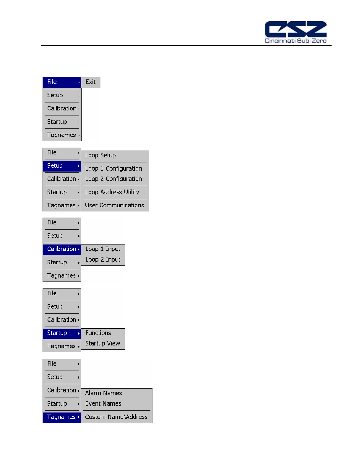
2.1 Configurator Menu
The configurator menu is accessed by pressing the “Monitor” icon at the top left of the screen.
After selecting this m enu item and exiting the c onfigurator, the
controller runtime software will run after the unit is re-powered.
The Setup menu provides access to the primary controller
setup options. These options include
communications sel ection and the loop addr ess utility that can
be used to automatically assign the proper communications
address to an attached loop control board.
The Calibration menu provides access to the input offset
calibration settings for the loop control boards .
The Startup m enu prov ides acces s to enab le an d dis abl e EZT430i runtime screens/menus and the desired startup view
selection.
The Tagnames menu provides access to the text editing
functions of the configurator which allow the event and alarm
names to be changed to m atch their use in the system. The
information that is shown when the runtime application starts.
2.2 CSZ EZT-430i Configurator Overview
EZT-430i
3 Configuring EZT-430i
IMPORTANT: Once all configuration settings ar e m ade, y o u m us t select “Exit” from the File men u to ex it t he
configurator prior to cy cling power to EZT-430i. All configuration f iles are wr itte n upon ex iting
the configurator. Do not c ycle power prior to exiting the config urator or settings will be lost
and EZT-430i will not operate properly when entering the runtime application.
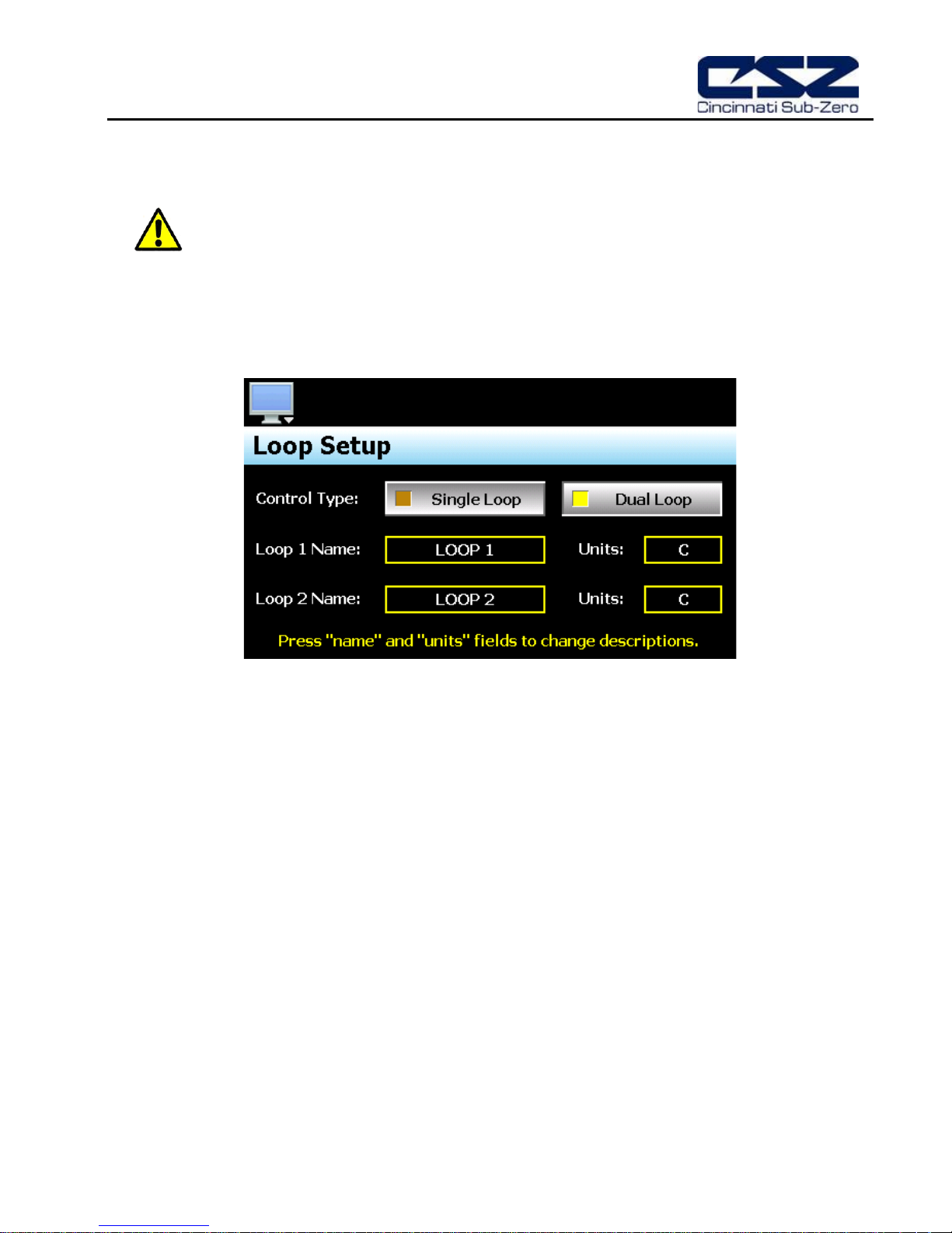
3.1 Loop Setup
The “Loop Setup” screen is acc essed f rom the Setup m enu. It prov ides the control type selec tion and entries
for setting the loop names and display units.
The Control Type selection sets the number of loop control boards that will be attac hed to EZT-430i, one
(single loop) or two (dual loop). When the EZT-430i runtime application is s tart e d, EZT-430i will autom at ically
configure all loop view displays, charts and available data log point selections based on the control type
selection and individual loop setup.
The Loop Name fields are used to enter a s pecific na me for eac h control loop , up to 11 c haracters i n length.
This name will be used throughout the EZT-430i runtime application and can be used to provide a more
detailed description as to the function of the loop in the application. Default tag names are LOOP 1 and
LOOP 2.
The Units fields are used to enter the engineering units for the loop with up to four characters maximum .
This value is shown on the singl e and dua l view loop s creens in the EZT-430i runtim e application. W hen the
loop input t ype selection is set for temperature, the field w ill be fixed at either “C” or “F” based on the units
selection for the loop unde r loop setup. If the loop input t ype is set for a linear input type (0-1 0V or 4-20mA
for example), the engineer i ng un its c an be e dit ed an d c hange d to th e r equ ired u ni ts f or the m eas ured pr ocess
value.
Configuring CSZ EZT-430i A.1
EZT-430i
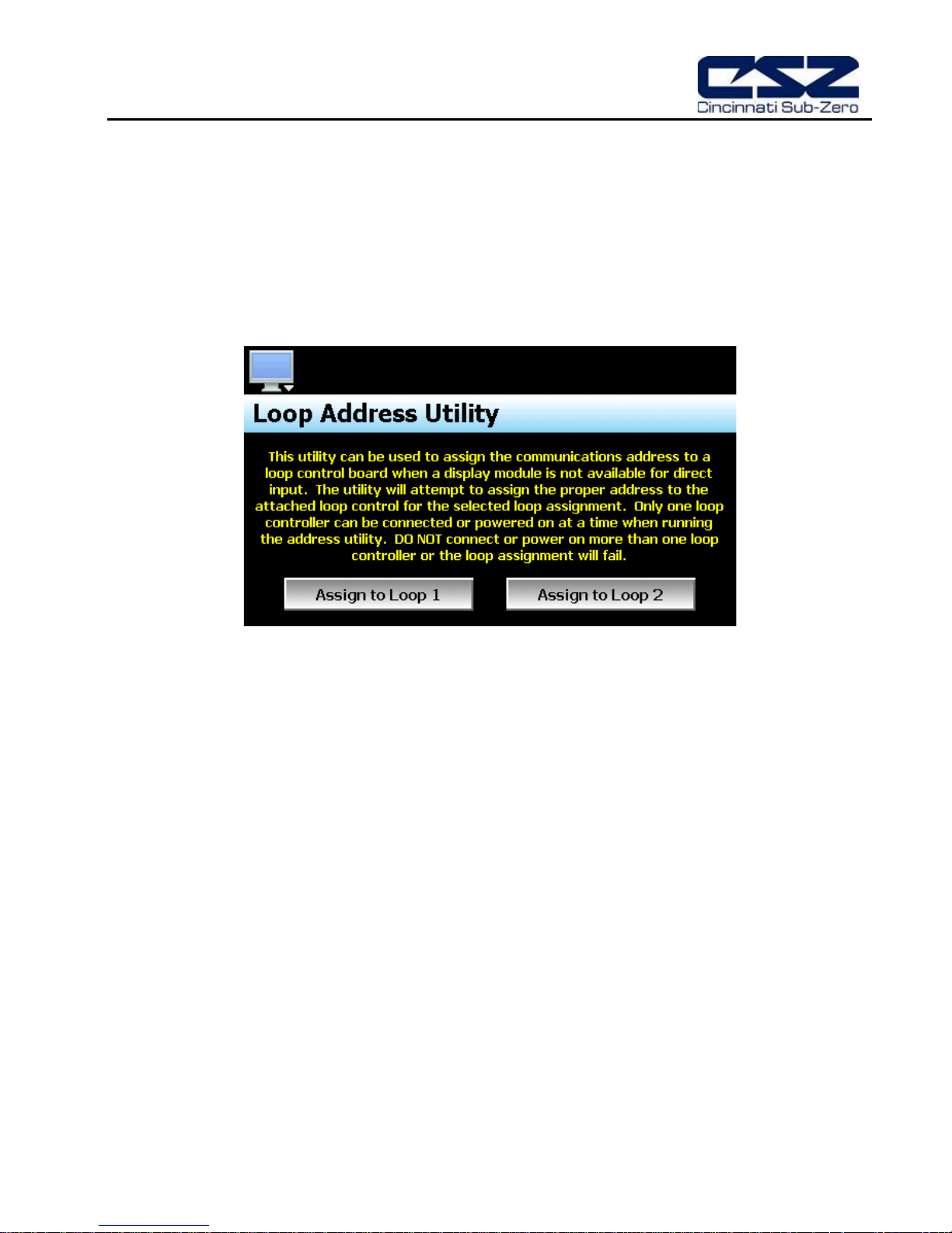
3.2 Loop Address Utility
In order for EZT-430i to properl y communicate with eac h of the loop contr ol boards, they m ust be configured
for the proper communications address. The factory default communication settings of the loop control
boards are set for a c ommunicat ions addres s of on e, which cor respond t o the pr oper settings for loop 1. For
a single loop EZT-430i contr ol system, no further s ettings are required . Simply connect the com munications
wiring between the control board and the EZT-430i interface, and the system is ready to go.
For a dual loop EZT-430i control system, one of the control boards must be set for address two which
corresponds with loop 2 of EZT-430i. If a display m odule is not avai lable to c onn ect to the lo op co ntrol board
in order to set its address, the Loop Address Utility can be used. It is accessed from the Setup menu.
In order to use the ut ility, only one loop control boar d can be connected to EZT-430i at a time. S ince the
default address of all control boar ds are 1, if more than one was connec ted, they would both respond to th e
same command which would c ause them both to be set to a dif f erent addr es s. I f both loo p cont ro l bo ar ds are
connected, disconnect the communications wiring from the loop control board that you DO NO T want to set
the address on. An a lternative is to rem ove power from the loop contr ol board rather than discon necting the
communications wiring.
With only one loop control board powered on or connected to EZT-430i via the communications link, press the
“Assign to Loop” button for the loop that you want to assign the control board to. The utility will begin
scanning for the loop c ontrol b oard and set its addres s to the proper addres s on ce found. If the utilit y fails to
set the address, check the wiring to insure it is properly connected. If the loop control board has been
previously used for anot her app lication, it m ay be poss ible th at the addres s or other comm unications setti ngs
have been changed, w hich pr event th e ut ility from working. In th is c as e, a d isp lay module must be connec ted
to the loop control board to set the proper communications settings:
Address: 1 or 2 (for loop 1 or loop 2)
Baud rate: 9600
Parity: Even
IMPORTANT: The loop input number cor responds to the communicat ions address that must b e set in the
loop control board for EZT-430i to access it pr operly. If the communications address is not
set properly in the loop control, EZT-430i will not be able to communicate with it, or may
communicate with the wrong loop control and assign the incorrect set points and control
parameters to it.
A.2 CSZ EZT-430i Configuring
EZT-430i
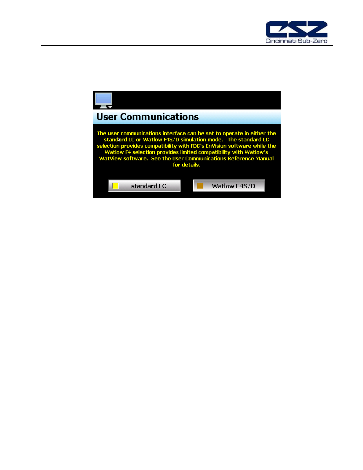
3.3 Use r Com m uni cati ons
The Modbus s lave inter face of EZT-430i can be set to operate in on e of t wo modes. T he default se tting is to
provide the standard us er interf ac e f or use with CSZ’s Envision sof tware. This selection assigns values to the
Modbus slave register table in the proper positions to allow communications between EnVision and EZT-430i.
The second selection c onfigures the Modbus sla ve interface to simulate the co mmunications interface f or a
“Watlow F4S/D” controller. This selection assigns EZT-430i control values to the corresponding register
addresses of a Watlow F4S/D control ler allowing limited com patibilit y with W atlow’s W atView s oftware. This
provides current users of the F4 controller and WatView software a control option for the replacement for
aging F4 controllers while k eeping the comm on software i nterface witho ut the need f or training on t he use of
different software.
IMPORTANT: The Watlow F4S/D interface is limited to basic set point adjustment, event output control;
profile operation and single profile download using WatView’s profile editor. Attempting
unsupported functions may cause errors in the operati on of WatView software an d require it
to be restarted.
See the EZT-430i Cincinnati User Communications Reference Manual for details on the use
of the Modbus slave interface including communications settings, register addresses and
their associated values as well as the functionality of the selected interface type.
Configuring CSZ EZT-430i A.3
 Loading...