

Page 1

PRELIMINARY
IQ Mixers
Software Manual
Page 1 of 18 ©2002 by Crown Audio Inc.
Page 2

Mixer/Multiplexer Control Panels ..................................................................................................................3
Mixer/Multiplexer Control Panel ................................................................................................................3
The Mixer/Multiplexers .............................................................................................................................. 3
MPX-6 .................................................................................................................................................... 3
SMX-6 .................................................................................................................................................... 3
AMB-5 .................................................................................................................................................... 4
Controls ..................................................................................................................................................... 5
Standard Controls..................................................................................................................................5
Mic/Line Controls................................................................................................................................5
PRELIMINARY
Mic/Line input.................................................................................................................................. 5
Net input gain..................................................................................................................................5
Input Level ......................................................................................................................................5
Input Label ...................................................................................................................................... 6
Output Label ...................................................................................................................................6
Data LED............................................................................................................................................6
Aux Out ..............................................................................................................................................6
Aux In ................................................................................................................................................. 7
Bus ..................................................................................................................................................... 7
Auto .................................................................................................................................................... 7
Output level meters ............................................................................................................................ 7
Toolbar ............................................................................................................................................... 7
User Labels ........................................................................................................................................8
"Auto" control access .........................................................................................................................8
"Auto" Controls....................................................................................................................................... 8
"Auto" Control Pages.......................................................................................................................... 8
Active "Auto" functions .......................................................................................................................9
Gate.................................................................................................................................................. 10
Duck Priority ..................................................................................................................................... 11
Input Compressor/Limiter.................................................................................................................11
Auto-level .........................................................................................................................................12
Output Compressor/Limiter .............................................................................................................. 13
Gate Count ....................................................................................................................................... 14
Crown Local Net...............................................................................................................................15
Ambience .........................................................................................................................................16
Page 2 of 18 ©2002 by Crown Audio Inc.
Page 3

Mixer/Multiplexer Control Panels
Mixer/Multiplexer Control Panel
The Mixer/Multiplexer Control Panel is a window within IQ for Windows that can be used to control any
of the set of Crown IQ-compatible mixer/multiplexer products: the MPX-6, the SMX-6 and the AMB-5.
Each of these products has several software controls in common. These include:
P
5 (the AMB-5) or 6 Mic/line inputs
"Data" LED switch
Aux Out switch
Aux In Indicator
RE
2 Audio Bus switches
The Toolbar
2 User Labels
The Mixer/Multiplexers
L
MPX-6
IM
The MPX-6 is a 6x2 mixer/multiplexer with six mic/line inputs, two main line level outputs and two
switchable bus outputs. Under computer control, it can switch the inputs on or off, control their levels, and
route them to two main and two bus outputs. Multiple MPX-6s can be connected together to create larger
systems.
Software controls:
I
6 Mic/line inputs
N
"Data" LED switch
Aux Out switch
Aux In Indicator
A
2 Audio Bus switches
The Toolbar
R
2 User Labels
SMX-6
Y
The SMX-6 is a sensing 6x2 mixer/multiplexer with six mic/line inputs, two main line-level outputs and two
switchable bus outputs. It contains a sensing circuit at the beginning of each input to sense the input
signal level ahead of any signal processing. Similar sensors are located at each output channel. These
sensors, along with its on-board intelligence, enable the SMX-6 to perform many versatile functions like
automatic mixing , compression, limiting and automatic level control. In addition an SMX-6 also has all the
manual switching and routing capabilities of an
Software Controls:
6 Mic/line inputs
"Data" LED button
Aux Out button
Aux In Indicator
2 Audio Bus buttons
1 Auto button
MPX-6.
Page 3 of 18 ©2002 by Crown Audio Inc.
Page 4

1 Auto Control Access button
8 pages of Auto controls:
1. Active - all Active Auto functions
2. Gate - the Gate function
3. Duck Priority - the Duck Priority function
4. Input Compressor - the Input Compressor/Limiter function
5. Auto Level - the Auto Level function
6. Output Compressor - the Output Compressor/Limiter function
PR I
7. Gate Count - the Gate Count function
8. Crown Local Net - the Crown Local Net functions
The Toolbar
2 User Labels
AMB-5
EL
The AMB-5 is two mixer/multiplexers in one unit. One mixer/multiplexer is an ambient sensing 5x1
mixer/multiplexer. It has all of the capabilities of Channel 1 of an SMX-6 plus the added feature of
ambient sensing. Its custom Ambience function enables it to automatically adjust the level of its mix to
match the ambient noise level. The second mixer/multiplexer is a basic 6x1 mixer/multiplexer much like
Channel 2 of an MPX-6. It offers remote control of Channel 2 from the host computer but it has none of
the automatic features like those provided by the Auto functions of Channel 1.
M
Software controls
6 Mic/line inputs
"Data" LED button
I
Aux Out button
Aux In Indicator
N
2 Audio Bus buttons
1 Auto button
1 Auto Control Access button
A
8 pages of Auto controls:
R
1. Active - all Active Auto functions
2. Gate - the Gate function
3. Duck Priority - the Duck Priority function
4. Input Compressor - the Input Compressor/Limiter function
Y
5. Auto Level - the Auto Level function
6. Output Compressor - the Output Compressor/Limiter function
7. Gate Count - the Gate Count function
8. Ambience - the Ambience functions
The Toolbar
2 User Labels
Page 4 of 18 ©2002 by Crown Audio Inc.
Page 5

Controls
Standard Controls
Mic/Line Controls
Mic/Line input
Applies To
MPX-6, SMX-6, AMB-5 except where noted
PRELIMINARY
The Mic/Line Input controls the amount of gain from an input channel to each of the two output channels.
Each Mic/Line Input can be controlled through the manipulation of a pair of slider controls located at the
top of the mixer control panel. The gain of each Mic/Line Input is controlled separately for each output
channel. When a gain control is turned down as far as it will go, the input will be turned off for that
channel. The range of the input level is -40 to +25 dB in 1/2-dB increments at the top of the scale and 100 to -40 dB in 5-dB steps at the bottom of the range.
Each Mic/Line Input also includes an input label and two smaller output labels. These labels not only
identify the input and output channels of the mic/line input, but can also be used to copy settings from one
Mic/Line Input to another.
SMX-6 and AMB-5 only
When the input control is being affected by one or more of the Auto functions available on the SMX-6 or
the AMB-5, a second "phantom" input slider may be visible that represents the net input gain at that point.
That is, it reflects the input level as affected by any of the Auto gates, limiters, compressors, etc., and
their relation to the Max Gain setting.
Net input gain
Applies To
SMX-6, AMB-5
The net gain of an input is the amount of gain that is applied from an input channel to one of the output
channels after the application of all enabled Auto functions. The net gain of each input is displayed along
with the mic/line input gain on the control panel. If the Auto functions of the mixer are turned off, then the
net gain is equal to the mic/line input gain. If, however, Auto is turned on then the net gain can be
expected to differ from the mic/line input gain. When this is the case, the net gain will be displayed as a
"phantom" fader for any input/output channel where it differs from the mic/line input gain. The net gain
slider may move actively, showing the operation of the various Auto functions. The reason that this is
called the "net" gain is because the gain settings may be the result of several Auto functions working
together.
Input Level
Applies To
SMX-6, AMB-5
The peak input level of each audio input is represented by a moving bar graph in the center of the mic/line
input.
Page 5 of 18 ©2002 by Crown Audio Inc.
Page 6

Input Label
Applies To
MPX-6, SMX-6, AMB-5
The input labels number both the mic/line inputs of all of the IQ mixer products and the expanded input
sections of the SMX-6 and the AMB-5. You can use this label to copy the settings of one input channel to
another channel. This is accomplished by "drag-and-drop:"
1) Click on the label of the input whose settings you wish to copy.
PRELIMINARY
2) While holding the mouse down, drag the cursor over the input section that you want to receive the
copied settings.
3) Release the mouse button.
Note that in the case of the SMX-6 and the AMB-5, the settings copied are only
function designated by the
and not all of the settings.
Output Label
Applies To
MPX-6, SMX-6, AMB-5
The output labels number input sliders as belonging to the outputs, 1 or 2, of the mixer. The mic/line
inputs of all of the IQ mixer products and the Auto Control Pages of the SMX-6 include these labels. The
input designation 1 through 6 and the output designation 1 or 2 combine to give you a single input/output
channel (e.g. input 4 / output 2). You can use these labels to copy all of the settings of one input/output
channel to any other input/output channel. This is accomplished by "drag-and-drop:"
1) Click on the output label of the input/output channel whose settings you wish to copy.
2) While holding the mouse down, drag the cursor over the input/output section that you want to receive
the copied settings.
3) Release the mouse button.
Note that in the case of the SMX-6 and the AMB-5 the settings copied are only
function designated by the
those related to the Auto
Auto Control Page
those related to the Auto
Auto Control Page
and not all of the settings.
Note: If you drag the settings of one input/output channel over the input label, then both outputs of that
input channel will be affected.
Data LED
Applies To
MPX-6, SMX-6, AMB-5
Every IQ mixer component is equipped with a data light that normally flashes only during those moments
when performing serial communications. This button will allow you to set it so the "Data" LED is fixed on.
Aux Out
Applies To
Page 6 of 18 ©2002 by Crown Audio Inc.
Page 7
MPX-6, SMX-6, AMB-5
Use the Aux out button control to turn the output auxiliary port of the unit on and off. When on, +15 VDC
is supplied across pins 1 (ground) and 3 (+):
Aux In
Applies To
MPX-6, SMX-6, AMB-5
P
The Aux In indicator will "light up" when the presence of an input signal (5 to 30 VDC) is detected across
pins 1 (ground) and 2 (+) of the Aux port:
R
Bus
E
Applies To
MPX-6, SMX-6, AMB-5
L
Each IQ mixer/multiplexer has two switchable "bus" outputs (one for each output channel). They receive
the exact same post-fader audio signal that the main outputs receive. They are turned on and off with the
Bus controls.
I N RY
M
Auto
Applies To
SMX-6, AMB-5
I
Use the Auto button control to activate any of the Auto functions that you have set up in your
mixer/multiplexer.
A
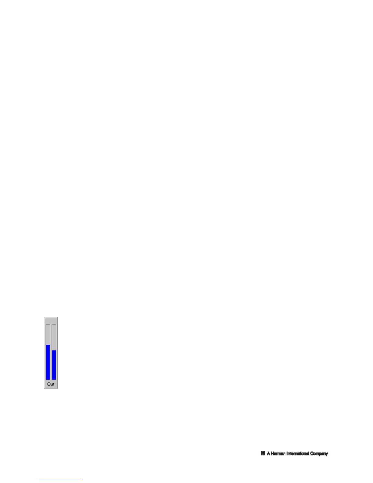
Output level meters
Applies To
SMX-6, AMB-5.
The peak output level of each channel is shown by the blue bar graphs on the right side of the
control panel
Toolbar
Applies To
Page 7 of 18 ©2002 by Crown Audio Inc.
Page 8

MPX-6, SMX-6, AMB-5
The Toolbar provides cut, copy and paste functions for the control panel. The settings that are cut or
copied to the clipboard are those that are displayed in the area immediately above the Toolbar. If a
control panel has not been expanded by pressing
of mixer control settings are moved to the clipboard. If, however, a control page is displayed, the Toolbar
moves from its location in the basic form of the control panel to a position directly under the control page.
This indicates that any settings cut or copied here will be only
not those from the area of the control panel above the control pages.
P
The paste function, as performed from the Toolbar, operates the same whether the control panel has
been expanded or not. It will paste whatever settings are currently in the clipboard to the component
related to the control panel.
R
In addition to cut/copy/paste functions, the Toolbar also lets you perform a copy of control settings from
channel 1 to channel 2 and vice versa.
EL RY
Finally, clicking on the "Help" button displays this help system.
User Labels
Applies To
I
MPX-6, SMX-6, AMB-5
MI
The mixer control panels allow you to enter two user labels of 15 characters each. These labels can
contain any information that you wish. The text that you type into label 1 will also be used as the caption
for the title bar of the control panel. To change these labels, simply type in the text areas using common
Windows text-editing conventions. Note that text typed in the User Labels is saved in the dataframe only
and not in the actual components.
N
"Auto" control access
A
Applies To
SMX-6, AMB-5
This control allows you to expand the control panel so that you can access the Auto Control Pages.
expand the control panel so that Auto Control Pages are visible (note the arrows).
control panel so that Auto Control Pages are not shown (note the arrows).
"Auto" Controls
"Auto" Control Pages
Applies To
SMX-6, AMB-5
The IQ-compatible mixer components, the SMX-6 and the AMB-5, contain several Auto functions that
may be engaged by clicking on the Auto button at the top right of the control panel. To set up any of these
indicates that Auto Control Pages are currently not shown on the control panel. Click to
indicates that Auto Control Pages are currently visible on control panel. Click to contract the
(SMX-6 and AMB-5 only) then the basic set
those from the control page displayed and
Page 8 of 18 ©2002 by Crown Audio Inc.
Page 9

functions click on . This will expand the control panel, making Auto function controls
accessible through a series of control pages. To access the controls on any page, click on the appropriate
page tab.
Every Control Page will include 5 (AMB-5) or 6 (SMX-6) input sections that contain controls for signal
processing prior to output. The AMB-5 allows processing prior to output for channel 1 only, while the
SMX-6 allows processing prior to output for both channel 1 and channel 2. Consequently, the SMX-6 will
split each input section into input/output pairs. Any input/output section may be copied to any other on the
same page by dragging from the output label to another input/output section. You can also copy the entire
contents of an input section by dragging from the input label to another input section.
P
In addition to the control pages available, a special
R
page lets you view all of the Auto functions that are currently in force.
Auto functions available include:
E
The Gate function
Automatically toggles an input between a low and high level (called "gating") whenever an incoming audio
L
signal level passes a preset threshold level
The Duck Priority function
I
Controls the priority of each input and how much the low priority input will be attenuated or "ducked" when
a higher priority input is activated (its gate is activated). There are six different priority levels.
M
The Input Compressor/Limiter function
The Input Compressor/Limiter function controls the threshold, compression ratio and release time of a
feed-forward input compressor/limiter. There is a separate channel 1 and 2 compressor limiter for each
I
input.
N
The Auto Level function
The Auto Level function automatically adjusts the level of selected inputs to achieve a target level. Each
input has a separate channel 1 and 2 target level.
A
The Output Compressor/Limiter function
The Output Compressor/Limiter function controls the threshold compression ratio and release time of
each channel's output compressor/limiter.
R
The Gate Count function
The Gate Count function counts how many inputs are activated at any instant and applies a preset
Y
attenuation as the number increases to prevent feedback.
The Crown Local Net controls (SMX-6 only)
The Crown Local Net controls enable multiple SMX-6s to respond to external Duck and Gate Count
functions via Crown Local Net wiring.
The
Ambience function (AMB-5 only)
The Ambience function monitors an ambient sense input (Input 6) and automatically adjusts the mix
output level of Channel 1 up and down accordingly.
Active "Auto" functions
Applies To
SMX-6, AMB-5
Active
Page 9 of 18 ©2002 by Crown Audio Inc.
Page 10

The Active page of the
setup section of the control panel lets you view at a glance which Auto functions are currently in force. It
also lets you turn any function on or off for a particular input/output channel.
indicates that the control is off, click to turn it on.
indicates that the control is on, click to turn it off.
P IM
Auto functions that may be viewed or changed include:
The Gate function
R
The Duck Priority function
The Input Compressor/Limiter function
The Auto Level function
E
The Output Compressor/Limiter function
The Gate Count function
L
The input and output labels provide a method for copying these on/off switches from one input/output
channel to another.
Gate
Applies To
SMX-6, AMB-5
Access Gate functions by clicking on the "Gate" tab of the Auto control pages.
IN
"Gating" is one of the most important functions of the Auto functions. It shuts off (or attenuates) inputs
that aren't in use. Gating is often used to prevent feedback. If several mics in a system are on at the same
time, the system's gain could become so high that it rings with transients or breaks into feedback.
A
Lowering the overall gain is one way to fix this problem, but some mic levels might become too low.
Gating is a better solution. A microphone is "live" only when a sound is loud enough to open its gate (for
example, speaking, singing, etc.).
R
Each
contains five controls:
Y
Gate On/Off
This control turns the function on or off for the indicated input/output channel. Turning the gate function off
also turns off the Duck Priority and Gate Count functions for this channel.
The following three controls are all located on the same Multi-value Slider. If two or more are set to the
same value, you may need to move the top one in order to access the one under it.
Max Gain(dB, -100 to +25 in 1/2 dB steps)
The Max Gain is the gain setting that will be used when the gate is "open."
Gate Threshold
The Gate Threshold is the input level above which the gate will "open" and below which the gate will
"close."
Low Set (dB, -100 to +25 in 1/2 dB steps)
input/output channel
(dB, -100 to +25 in 1/2 dB steps)
Auto functions
Page 10 of 18 ©2002 by Crown Audio Inc.
Page 11

The Low Set is the gain setting that will be used when the gate is "closed."
Delay (0.2, 0.4, 0.6, 0.8, 1, 1.5 ,2, 3, 4, 6, 8, 10, 12, 15, 20, 30 seconds)
The Delay determines how long the gate will stay open after the incoming signal drops below the
Threshold.
SMX-6 only
In addition to these controls there is a "Max Open Mikes" control that affects the Gate function as a whole.
You can set "Max Open Mikes" for a value from 1 to 6. If the number of "open" gates is equal to this
P
value, then no more gates will be opened even when an input level is well above threshold. This control
can be set per output channel.
RE I
Duck Priority
Applies To
SMX-6, AMB-5
Access Duck Priority functions by clicking on the "Duck Priority" tab of the Auto control pages.
LI
"Ducking" is the attenuation of an input when another input with a higher priority
function. When the higher priority gate opens, all inputs with lower priorities drop or "duck" to their Low
Set values. To activate the Duck Priority function for a particular channel, turn it on and set the priority
level.
M
Each
scheme:
N
A
R
Y
Duck Priority On/Off
This control turns the function on or off for the indicated input/output channel.
Duck Priority Level(1 - 6)
The Duck Priority Level determines which input takes precedence. The priority can be set from 1 to 6 with
1 as the highest priority and 6 as the lowest. A separate priority setting is provided for each channel
making it possible to give an input a different priority for each output channel. The Duck Priority control is
ignored if either the Duck Priority or Gate controls are turned off.
IMPORTANT: The Duck Priority function is dependent on the Gate function. Both the Gate function and
the Duck Priority function must be enabled for Ducking to function.
Input Compressor/Limiter
Applies To
SMX-6, AMB-5
Access Input Compressor/Limiter functions by clicking on the "Input Compressor" tab of the Auto control
pages.
The input compressor/limiter function "reins in" input signals that suddenly become too loud. If the
excessive loudness of the input signal is not transitory, but is sustained, you might prefer to use the Auto
Level function to control it.
Each
is activated by the Gate
input/output channel contains a pair of controls that can be used to set the Duck Priority
input/output channel
Page 11 of 18 ©2002 by Crown Audio Inc.
Page 12

contains five controls:
Compressor/Limiter On/Off
This control turns the function on or off for the indicated input/output channel.
The following two controls are all located on the same Multi-value Slider. If they are set to the same
value, you may need to move the top one in order to access one under it.
Max Gain (dB, -100 to +25 in 1/2-dB steps)
P M Y
The Max Gain is the gain setting when no compression is taking place.
Threshold (dB, -100 to +25 in 1/2-dB steps)
R
The Threshold is the input level above which compression begins. A signal at this level or below is not
affected.
E
The control panel lets you display either the compression ratio or the release time for all input channels.
Select which is displayed by clicking on one of the selections in the "Show" control located on the right
side of the Input Compressor page.
L
Compression Ratio (1:1, 2:1, 4:1, 8:1, 16:1, 32:1, infinity:1)
The Compression Ratio is the amount of compression that is applied for every step over the Threshold.
I
Release Time (0.2, 0.4, 0.6, 0.8, 1, 1.5 ,2, 3, 4, 6, 8, 10, 12, 15, 20, 30 seconds)
The Release Time determines how long it takes for the gain to return to normal once the level drops
below the Threshold.
SMX-6 only
IN
In addition to the individual input controls, there is also a single "Slow Compression" control that applies
to all input channels. When Slow Compression is set to off, the compressor is set to the fastest attack
time possible. This will be very fast -- so fast the compressor can stop extremely sudden transients like
the sound caused by a dropped microphone. This is a good setting for rapid speech. You can turn the
A
Slow Compression on for more gentle sound sources such as most music.
Auto-level
R
Applies To
SMX-6, AMB-5
Access Auto Level functions by clicking on the "Auto Level" tab of the Auto control pages.
The Auto Level function is designed to control long-term changes in signal level. Using it, the average
output level can be kept relatively constant over a longer time interval while transients are allowed to
pass. This feature creates a more natural sound with increased dynamic range.
There are five different controls related to the Auto Level function for each input/output channel:
Auto Level On/Off
This control turns the function on or off for the indicated input/output channel.
The following three controls are all located on the same Multi-value Slider. If two or more are set to the
same value, you may need to move the top one in order to access one under it.
Max Gain (dB, -100 to +25 in 1/2-dB steps)
Page 12 of 18 ©2002 by Crown Audio Inc.
Page 13

The Max Gain is the upper limit for input gain, a gain ceiling when the Auto Level function is attempting to
raise the gain on a low-level signal.
Auto Level (dB, -100 to +25 in 1/2-dB steps)
The Auto Level control sets the desired average output level. This level can best be understood as a
"target" level. If the output signal level is above this level, the gain will be reduced to attempt to hit this
target. Likewise, if the output signal is lower than this level, the gain will be increased. In no case will the
gain level be set to greater than Max Gain.
Idle Gain (dB, -100 to +25 in 1/2-dB steps)
P
If the
Gate and Auto Level functions are used together, their interaction may produce an unexpected
side effect. When Max Gain is set above the Auto Level value, the Auto Level function could start
lowering the gain every time the gate opens. If there is a great difference between the signal level and the
RE
desired average output level, the shift in gain will be very noticeable. The sound would start out loud and
then fade.
The Idle Gain control can compensate for this situation. Idle Gain controls the initial gain when the gate
first opens. You can think of it as the "starting gain" because it overrides the Max Gain when the gate
opens. Start with Idle Gain equal to Max Gain. If the level audibly drops each time the gate opens, try a
lower value for Idle Gain. Note: Never set Idle Gain greater than Max Gain.
L
Reaction Time
The Auto Level function continually adjusts the signal level toward the Auto Level value. But it doesn't
I
adjust the signal in one jump. Instead, the Reaction Time control sets the length of time between steps.
MI
N
A
R
Y
In addition to these controls, there is a system-wide control that determines to what value the gain is
set when an input gate is opened. (Note that this control is only active when the gate function is on in
addition to the Auto Level function). "Open to Idle Gain" is best for systems with relatively constant sound
levels as with background music. "Open to Last Position" is best for systems with widely varying sound
levels where an Idle Gain setting is difficult to choose. When an input gate opens, the Idle Gain setting is
ignored and the gain is restored to the previous level it had just prior to its closing.
Output Compressor/Limiter
Applies To
SMX-6, AMB-5
Access Output Compressor/Limiter functions by clicking on the "Output Compressor" tab of the
control pages.
The Output Compressor/Limiter function keeps the output from exceeding a predetermined level. It's
especially valuable when used as an output limiter for the protection of amplifiers, loudspeakers and other
audio equipment.
For the Output Compressor/Limiter, compression of the signal at each input occurs only when the mix
exceeds the limit threshold. It doesn't matter how loud a particular input gets, the mix that feeds each
output channel must exceed the Limit Threshold before compression occurs.
Each of the two output channels has four controls:
Output compressor On/Off
This control turns the function on or off for the indicated output channel.
Limit Threshold
The Limit Threshold is used to set the peak signal level above which compression occurs.
(0.2, 0.4, 0.6, 0.8, 1, 1.5 ,2, 3, 4, 6, 8, 10, 12, 15, 20, 30 seconds)
(dB, -100 to +25 in 1/2 dB steps)
Auto
Page 13 of 18 ©2002 by Crown Audio Inc.
Page 14

Compression Ratio (1:1, 2:1, 4:1, 8:1, 16:1, 32:1, infinity:1)
The Compression Ratio controls the amount of compression that is applied for every step over the
Threshold.
Release Time (0.2, 0.4, 0.6, 0.8, 1, 1.5 ,2, 3, 4, 6, 8, 10, 12, 15, 20, 30 seconds)
The Release Time determines how long it takes for the gain to return to normal when the level drops
below the Threshold.
In addition every
P
contains two controls:
R I A
Output Compressor/Limiter On/Off
turns the function on or off for the indicated input/output channel. That is, turning the compressor/limiter
E
on here results in this input being included among those whose input will be compressed in an attempt to
limit the output to Threshold.
L
Max Gain
(dB, -100 to +25 in 1/2 dB steps)
I
The Max Gain is the gain setting of the input when no compression is active.
M
Gate Count
Applies To
SMX-6, AMB-5
Access Gate Count functions by clicking on the "Gate Count" tab of the Auto control pages.
N
The Gate Count function keeps track of how many gates are open at a time, and provides feedback
control when a large number of mics are open. The Gate Count function is dependent on the
function. Both the Gate function and the Gate Count function must be on for the latter to have any effect.
Two main controls form the basis for the Gate Count function:
R
Gate Count On/Off
Use the master on/off switch labeled "Master" to turn the Gate Count function on or off.
Y
Gate Count Level (1/2 to 3 dB in 1/2-dB steps; 3 to 12 dB in 1-dB steps; 16 dB)
The Gate Count Level determines how much each input is attenuated as more gates open. When only
one mic in a count group is active, there is no added attenuation. Each additional open mic increases the
attenuation by the "Count Level."
Each
input/output channel contains 2 additional controls:
Gate Count On/Off
This control turns the function on or off. If this control is turned on, the input is counted as an open gate
when its input level is above Gate Threshold. Turning the gate count function off means that this input will
not be included as an open gate even if the gate is open.
Max Gain (dB, -100 to +25 in 1/2 dB steps)
input/output channel
Gate
Page 14 of 18 ©2002 by Crown Audio Inc.
Page 15

Max Gain is the gain setting that will be used when the gate is "open," and no further attenuation is
indicated.
Crown Local Net
Applies To:
SMX-6
Access Crown Local Net functions by clicking on the "Crown Local Net" tab of the Auto control pages.
PRELIMINARY
Use of the Crown Local Net allows multiple SMX-6s to be linked so that their Duck Priority and
Count functions work together. For example, a duck priority 1 in one unit will override a priority 2 in
another unit. Likewise on the gate count side, the number of open mics can be totaled among all the
SMX-6s in a Crown Local network and all open inputs attenuated to prevent feedback in a large system.
The Crown Local Net must be set up in a particular order for reliable operation of cooperating functions.
The procedure is listed below.
1. All SMX-6s must
2.
Auto must be turned on for all connected units.
3. With the Crown Local Net wiring disconnected
External Functions, Duck and Gate Count controls.
4. Connect the Crown Local Net serial cables as described in the IQ Mixer/Multiplexer Hardware
Installation Manual.
5. Select the Master SMX-6 and turn the System control on. The Crown Local Net will begin to function
on its own.
After the Crown Local Net has been properly initialized, the System control can be turned on/off at any
time to enable or disable Crown Local Net communication.
WARNING: You will be locked out of any further serial port communication with an SMX-6 when
you initialize the Crown Local Net.
The Crown Local Net controls are described below. It is important to turn the System control on last as
described in the previous Crown Local Net startup procedure.
One of the first things to do is to decide which SMX-6 will serve as the Crown Local Net master. Being the
Crown Local Net master will not affect its normal operation. After the master is selected, the Duck, Gate
Count and External Functions controls should be set for each SMX-6.
System On/Off
This control activates the Crown Local Net. It should only be turned on for the first time after all of the
following controls have been set. The startup procedure above gives specific instructions how to do this.
Select the master SMX-6 before turning it on.
Master On/Off
This control selects the master SMX-6 as required by the startup procedure. One and only one SMX-6
should be the master. Neither the Crown Local Net nor the SMX-6s will function properly if more than one
unit is selected as a master.
External Functions On/Off
be connected to the system via the Crown Bus.
and the System control turned off, set the Master,
Gate
Page 15 of 18 ©2002 by Crown Audio Inc.
Page 16

Turn this control on for any SMX-6s that you want to participate in the Crown Local Net.
Duck On/Off
Turn this control on for all SMX-6s in a Crown Local Net that you want to respond to external Duck Priority
functions.
Gate Count On/Off
Turn this control on for all SMX-6s in a Crown Local Net that you want to respond to external Gate Count
functions.
P
Ambience
R
Applies To
AMB-5
EL
Access Ambience functions by clicking on the "Ambience" tab of the Auto control pages.
The Ambience function is unique to the AMB-5. The Ambience function monitors the ambient sense input
(Input 6) and automatically adjusts the mix output level of Channel 1 up or down accordingly. This
enables the AMB-5 to automatically mix and control the overall loudness in an environment with
background noise levels that vary.
I
Functionally, the ambience function operates after all other functions have processed the audio signals.
M
You can think of the ambience function as a "black box" that sits after all other audio functions.
Each input (1 - 5) of Channel 1 contains a single control:
I
Max Gain (dB, -100 to +25 in 1/2 dB steps)
The Max Gain is the upper limit for input gain. It is a gain ceiling when the Ambience function is
N
attempting to raise the gain due to a high ambient level.
The main controls that affect the ambience function are:
A
Ambience On/Off
This control turns the Ambience function on or off
RY
Ambient Offset
The Ambient Offset is the level below Max Gain to which the Channel 1 gain will be set until the ambience
level exceeds the Threshold setting. As the ambience level increases above the Threshold setting, the
Channel 1 gain will be increased above the Ambient Offset according to the Expansion Ration setting.
The Max Gain setting always limits the maximum possible gain that any input can receive.
Threshold
The Threshold determines at what ambient sound level the Ambience function will begin to operate. It is
the sound pressure level of the ambient sensing input (Input 6). When the signal level of Input 6 exceeds
the Threshold setting, the Ambience function begins to increase the gain of Channel 1 at a rate dictated
by the Expansion Ratio control.
Expansion Ratio
The Expansion Ratio determines how much the gain of output Channel 1 will increase for every increase
in the ambient signal level above the Threshold setting. A 4:1 Expansion Ratio setting will raise the output
gain 1 dB for every 4 dB that the ambient signal increases.
Attack Time
(dB, 0 to +40 in 1/2-dB steps)
(dB, -100 to +25 in 1/2-dB steps)
(1:1, 1.5:1, 2:1, 2.5:1, 3:1, 4:1, 5:1)
(0.2, 0.4, 0.6, 0.8, 1, 1.5 ,2, 3, 4, 6, 8, 10, 12, 15, 20, 30 seconds)
Page 16 of 18 ©2002 by Crown Audio Inc.
Page 17

The Attack Time determines how rapidly the Ambience function will begin to increase the output level of
Channel 1 above the Ambient offset level once the level of Input 6 exceeds the Threshold.
Decay Time (0.2, 0.4, 0.6, 0.8, 1, 1.5 ,2, 3, 4, 6, 8, 10, 12, 15, 20, 30 seconds)
The Decay Time determines how rapidly the Ambience function will begin to reduce the output level of
Channel 1 while the ambient sense input level is dropping.
PRELIMINARY
Page 17 of 18 ©2002 by Crown Audio Inc.
Page 18

"Auto" control access, 8
"Auto" functions, 7, 8, 9, 10, 11, 12, 13, 14, 15,
16
Active, 9
Ambience, 16
Auto-level, 12
Crown Local Net, 15
Duck Priority, 11
Gate, 10
P IM ARY R
E
L
I
N
Gate Count, 14
Input Compressor/Limiter, 11
Output Compressor/Limiter, 13
turning on, 7
Active "Auto" functions, 9
AMB-5, 4
Ambience, 16
Auto, 7
Auto-level, 12
Aux In, 7
Aux Out, 6
Bus, 7
Compressor, 11, 13
Input, 11
Output, 13
Copying, 6
Input Channels, 6
Input/Output Channels, 6
Crown Local Net, 15
Data LED, 6
Duck Priority, 11
Gate, 10
Gate Count, 14
Input Compressor/Limiter, 11
Input Label, 6
Input Level, 5
Labels, 6, 8
Input, 6
Output, 6
User, 8
Levels, 5, 7
Input, 5
Output, 7
Limiter, 11, 13
Input, 11
Output, 13
Mic/Line input, 5
Mixer/Multiplexer Components, 3, 4
AMB-5, 4
MPX-6, 3
SMX-6, 3
Mixer/Multiplexer Control Panel, 3, 8
expanding/contracting, 8
Mixer/Multiplexer Controls, 5, 6, 7, 8
Aux In, 7
Aux Out, 6
Bus, 7
Data LED, 6
Mic/Line inputs, 5
Toolbar, 7
User Labels, 8
MPX-6, 3
Net input gain, 5
Output Compressor/Limiter, 13
Output Label, 6
Output level meters, 7
SMX-6, 3
Toolbar, 7
User Labels, 8
Page 18 of 18 ©2002 by Crown Audio Inc.
 Loading...