

Crown Commercial Audio User Manual
Commercial Audio Series
Operation Manual
T
B
T
B
T
T
B
Obtaining Other Language Versions:
B
To obtain information in another language about the use of this product, please contact your
local Crown Distributor. If you need assistance locating your local distributor, please contact Crown at 574-294-8000.
This manual does not include all of the details of design, production, or variations of the equipment. Nor does it cover every possible
situation which may arise during installation, operation or maintenance.
The information provided in this manual was deemed accurate as of the publication date. However, updates to this information may have
occurred. To obtain the latest version of this manual, please visit the Crown website at www.crownaudio.com.
Trademark Notice:
Crown, Crown Audio and Amcron are registered trademarks of Crown International. Other trademarks are the
property of their respective owners.
180A
1160A
280A
660A
Some models may be exported under the name Amcron.
®
©2007 by Crown Audio® Inc., 1718 W. Mishawaka Rd., Elkhart, Indiana 46517-9439 U.S.A. Telephone: 574-294-8200
138099-4C
9/07
Important Safety Instructions
Commercial Audio Series Amplifiers
1) Read these instructions.
2) Keep these instructions.
3) Heed all warnings.
4) Follow all instructions.
5) Do not use this apparatus near water.
6) Clean only with a dry cloth.
7) Do not block any ventilation openings. Install
in accordance with the manufacturer’s instructions.
8) Do not install near any heat sources such as
radiators, heat registers, stoves, or other
apparatus (including amplifiers) that produce
heat.
9) Do not defeat the safety purpose of the polarized or grounding-type plug. A polarized plug
has two blades with one wider than the other.
A grounding-type plug has two blades and a
third grounding prong. The wide blade or the
third prong is provided for your safety. If the
provided plug does not fit into your outlet,
consult an electrician for replacement of the
obsolete outlet.
10) Protect the power cord from being walked on
or pinched, particularly at plugs, convenience
receptacles, and the point where they exit from
the apparatus.
11) Only use attachments/accessories specified
by the manufacturer.
12) Use only with a cart, stand, tripod, bracket, or
table specified by the manufacturer, or sold
with the apparatus. When a cart is used, use
caution when moving the cart/apparatus combination to avoid injury from tip-over.
13) Unplug this apparatus during lightning storms
or when unused for long periods of time.
14) Refer all servicing to qualified service personnel. Servicing is required when the apparatus
has been damaged in any way, such as powersupply cord or plug is damaged, liquid has
been spilled or objects have fallen into the
apparatus, the apparatus has been exposed to
rain or moisture, does not operate normally,
or has been dropped.
15) WARNING: TO REDUCE THE RISK OF FIRE
OR ELECTRIC SHOCK, DO NOT EXPOSE
THIS APPARATUS TO RAIN OR MOISTURE.
16) DO NOT EXPOSE TO DRIPPING OR SPLASHING. DO NOT PLACE OBJECTS FILLED WITH
LIQUID, SUCH AS VASES,ON THIS APPARATUS.
TO COMPLETELY DISCONNECT THIS EQUIPMENT
FROM THE AC MAINS, DISCONNECT THE POWER
SUPPLY CORD PLUG FROM THE AC RECEPTACLE. THE MAINS PLUG OF THE POWER SUPPLY
CORD SHALL REMAIN READILY OPERABLE.
TO PREVENT ELECTRIC SHOCK DO NOT REMOVE
TOP OR BOTTOM COVERS. NO USER SERVICEABLE PARTS INSIDE. REFER SERVICING TO
QUALIFIED SERVICE PERSONNEL.
À PRÉVENIR LE CHOC ÉLECTRIQUE N’ENLEVEZ
PAS LES COUVERCLES. IL N’Y A PAS DES PARTIES SERVICEABLE À L’INTÉRIEUR. TOUS REPARATIONS DOIT ETRE FAIRE PAR PERSONNEL
QUALIFIÉ SEULMENT.
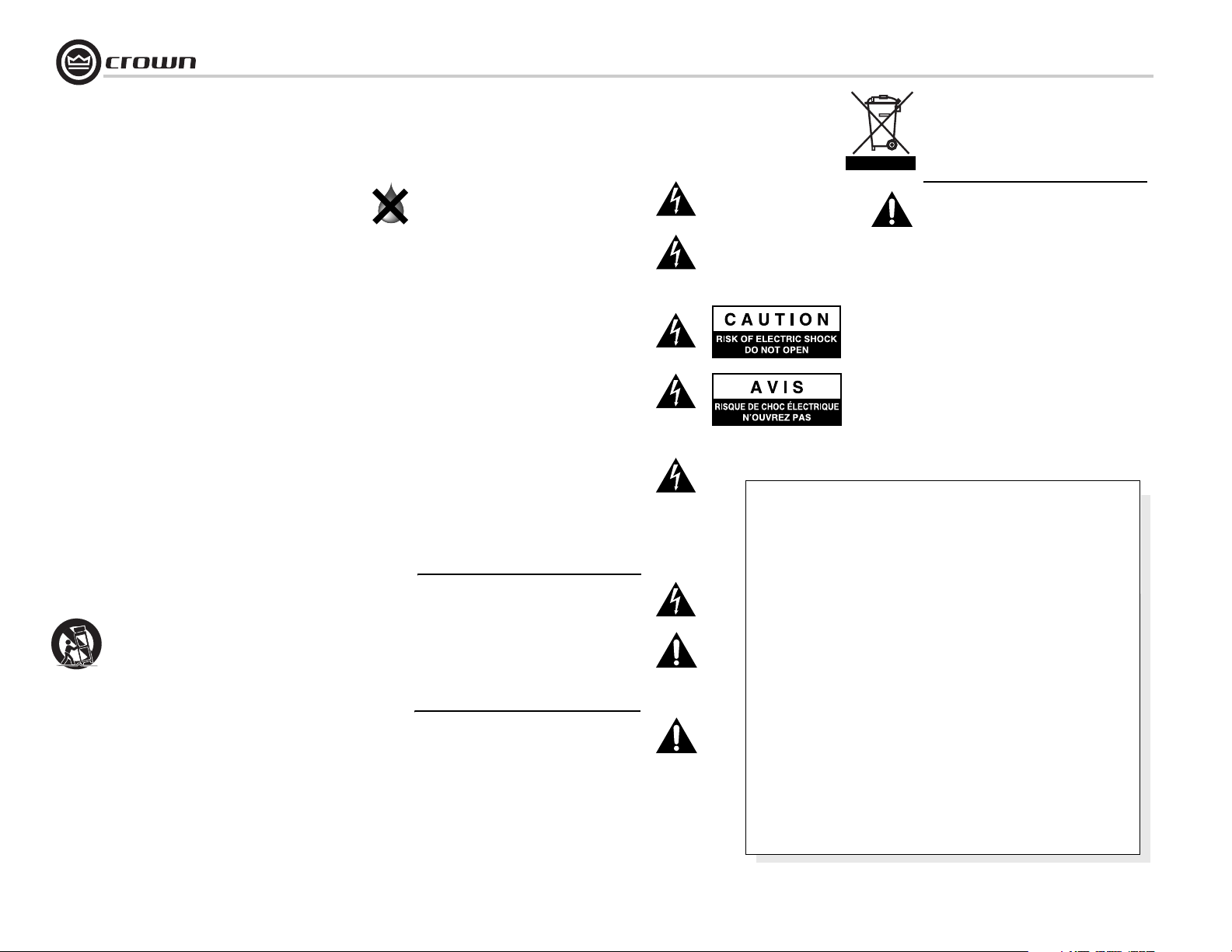
WATCH FOR THESE SYMBOLS:
The lightning bolt triangle is used to alert the user
to the risk of electric shock.
The exclamation point triangle is used to alert the
user to important operating or maintenance instructions.
IMPORTANT
Commercial Audio Series amplifiers require Class 2
output wiring.
MAGNETIC FIELD
CAUTION! Do not locate sensitive high-gain equipment such as preamplifiers or tape decks directly
above or below the unit. Because this amplifier has
a high power density, it has a strong magnetic field
which can induce hum into unshielded devices that
are located nearby. The field is strongest just above
and below the unit.
If an equipment rack is used, we recommend locating the amplifier(s) in the bottom of the rack and the
preamplifier or other sensitive equipment at the top.
FCC COMPLIANCE NOTICE
This device complies with part 15 of the FCC rules. Operation is subject to the following
two conditions: (1) This device may not cause harmful interference, and (2) this device
must accept any interference received, including interference that may cause undesired
operation.
CAUTION: Changes or modifications not expressly approved by the party responsible for
compliance could void the user’s authority to operate the equipment.
NOTE: This equipment has been tested and found to comply with the limits for a Class B
digital device, pursuant to part 15 of the FCC Rules. These limits are designed to provide
reasonable protection against harmful interference in a residential installation. This
equipment generates, uses, and can radiate radio frequency energy and, if not installed
and used in accordance with the instruction manual, may cause harmful interference to
radio communications. However, there is no guarantee that interference will not occur in a
particular installation. If this equipment does cause harmful interference to radio or television reception, which can be determined by turning the equipment off and on, the user is
encouraged to try to correct the interference by one or more of the following measures:
• Reorient or relocate the receiving antenna.
• Increase the separation between the equipment and receiver.
• Connect the equipment into an outlet on a circuit different from that to which the
receiver is connected.
• Consult the dealer or an experienced radio/TV technician for help.
page 2
Operation Manual
Commercial Audio Series Amplifiers
Crown International, Inc.
Issued By: Crown International, Inc.
1718 W. Mishawaka Road
Elkhart, Indiana 46517 U.S.A.
European Representative’s Name and Address:
Nick Owen
35, Bassets Field
Thornhill
Cardiff. South Glamorgen
CF14 9UG United Kingdom
Equipment Type: Commercial Audio Series
Family Name: Amplifiers
Model Names: 180A, 280A, 1160A, 660A
EMC Standards:
EN 55103-1:1997 Electromagnetic Compatibility - Product Family Standard for Audio, Video, Audio-Visual and Entertainment Lighting Control Apparatus for Professional Use, Part 1: Emissions
EN 55103-1:1997 Magnetic Field Emissions-Annex A @ 10 cm and 1 M
EN 61000-3-2:2001 Limits for Harmonic Current Emissions (equipment input current 16A per phase)
EN 61000-3-3:2002 Limitation of Voltage Fluctuations and Flicker in Low-Voltage Supply Systems Rated Current 16A
EN 55022:2003 Limits and Methods of Measurement of Radio Disturbance Characteristics of ITE: Radiated, Class B Limits; Conducted, Class B
EN 55103-2:1997 Electromagnetic Compatibility - Product Family Standard for Audio, Video, Audio-Visual and Entertainment Lighting Control Apparatus for Professional Use, Part 2: Immunity
EN 61000-4-2:2001 Electrostatic Discharge Immunity (Environment E2-Criteria B, 4k V Contact, 8k V Air Discharge)
EN 61000-4-3:2001 Radiated, Radio-Frequency, Electromagnetic Immunity (Environment E2, Criteria A)
EN 61000-4-4:2001 Electrical Fast Transient/Burst Immunity (Criteria B)
EN 61000-4-5:2001 Surge Immunity (Criteria B)
EN 61000-4-6:2003 Immunity to Conducted Disturbances Induced by Radio-Frequency Fields (Criteria A)
EN 61000-4-11:2001 Voltage Dips, Short Interruptions and Voltage Variation
Safety Standard:
IEC 60065: 2002 7th Ed. Safety Requirements - Audio Video and Similar Electronic Apparatus
CAN/CSA-E60065-03 7th Ed. Audio, Video and Similar Electronic Apparatus-Safety Requirements
UL 60065 7th Ed. Audio /Video and Musical Instrument Apparatus for Household, Commercial and Similar General Use.
DECLARATION of CONFORMITY
FOR COMPLIANCE QUESTIONS ONLY:
Sue Whitfield
574-294-8289
swhitfield@crownintl.com
I certify that the product identified above conforms to the requirements of the EMC Council Directive 89/336/EEC as amended by 92/31/EEC, and the Low Voltage Directive 73/23/EES as amended by 93/68/EEC.
Signed
Date of Issue: Jan. 1, 2006
Operation Manual
Larry Coburn
Title: Senior Vice President of Manufacturing
Due to line current harmonics, we recommend that you contact your supply authority before connection.
page 3

Table of Contents
Commercial Audio Series Amplifiers
Important Safety Instructions .......................................................2
Declaration of Conformity ............................................................3
1 Welcome ................................................................................5
1.1 Features ...........................................................................5
1.2 Front Panel Controls and Indicators................................6
1.3 Back Panel Controls and Connectors................................7
1.4 66A Back Panel Controls and Connectors ........................8
2 Setup ......................................................................................9
2.1 Installation........................................................................9
2.2 How to Attach Rack Ears ...................................................9
2.3 Choose Input Wire and Connectors .................................10
2.4 Choose Output Wire and Connectors ...............................10
2.5 Wire Your System ............................................................11
2.6 Remote Volume Control....................................................13
2.7 Powering Up.....................................................................13
2.8 Included Accessories........................................................13
2.9 Optional Accessories........................................................13
3 Troubleshooting ..................................................................14
4 Specifications ..................................................................... 15
5 Service ... .............................................................................. 16
5.1 International and Canada Service ...................................16
5.2 US Service .....................................................................16
5.2.1 Service at a US Service Center .............................. 16
5.2.2 Factory Service ......................................................16
5.2.3 Factory Service Shipping Instructions ................... 16
5.2.4 Packing Instructions................................................ 16
5.2.5 Estimate Approval................................................... 16
5.2.6 Payment of Non-Warranty Repairs..........................16
6 Warranty .............................................................................. 17
Product Registration.................................................................... 19
Crown Factory Service Information Form .....................................21
page 4
Operation Manual
Commercial Audio Series Amplifiers
*
1 kHz
180A
Minimum guaranteed power
into 4 ohms or 70V/100V output
Power
80W
*1 kHz Power: refers to maximum power in watts at
1 kHz with 0.5% THD.
280A
Minimum guaranteed power
per channel into 4 ohms or
70V/100V output
*1 kHz Power: refers to maximum power in watts at
1 kHz with 0.5% THD.
1160A
Minimum guaranteed power
into 4 ohms or 70V/100V output
*1 kHz Power: refers to maximum power in watts at
1 kHz with 0.5% THD.
*
1 kHz
Power
80W
*
1 kHz
Power
160W
1 Welcome
The Crown® 180A, 280A, 1160A and 66A are
high-value amplifiers for commercial and
industrial audio. They provide 4-ohm and constant-voltage outputs (70V and 100V). The
660A, a six-channel amplifier, provides 4-ohm
and constant-voltage outputs (70V and 100V)
on channels 1 through 4, and 4-ohm outputs
on channels 5 and 6.
The amps are part of Crown’s Commercial
Audio Series, which also includes mixers and
mixer-amps. These low-cost units provide all
necessary features in a simple building-block
format.
Some applications include schools, hospitals,
factories, restaurant/retail, houses of worship,
fitness facilities, A/V boardrooms, prisons, and
small offices. Typical uses are paging, background music, security and evacuation instructions.
.The amplifiers vary in their number of inputs,
number of outputs, and power range:
• 180A has 1 input and one 80W power amplifier for single-zone systems.
• 280A has 2 inputs and dual 80W power
amplifiers for two-zone systems.
• 1160A has 1 input and one 160W power
amplifier for single-zone systems.
• 660A has six inputs and six 60W power
amplifier channels for multi-zone systems. It
can drive different types of speakers in different
areas of a facility.
The sound system can be upgraded as a facility
expands. For example, you can add more mixers for more inputs, or add more power amps
(or mixer-amps) to handle more zones.
T
B
T
B
1.1 Features
• 180A, 280A and 1160A have1 or 2 inputs, 1
or 2 amplifier output channels. 660A has 6
inputs and 6 amplifier output channels.
• Ideal for commercial and industrial use
• Expandable by adding Crown Commercial
Audio mixers or Commercial Audio mixeramplifiers
• Balanced Phoenix-type line inputs; touchproofed screw-terminal speaker outputs
• Advanced protection system includes output
current limiting, DC protection, circuit breaker/
fuse, and thermal protection. Details available
online at www.crownaudio.com.
• Three-Year, No-Fault, Fully Transferable
Warranty completely protects your investment
and guarantees its specifications
660A
Minimum guaranteed power
into 4 ohms or 70V/100V
output
*1 kHz Power: refers to maximum power in watts at
1 kHz with 0.5% THD.
Operation Manual
*
1 kHz
Power
60W
page 5
1 Welcome
Commercial Audio Series Amplifiers
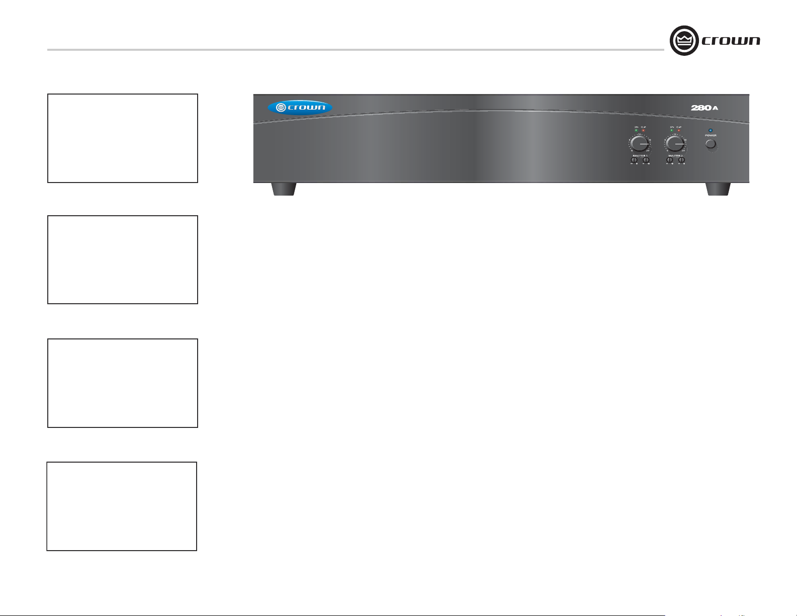
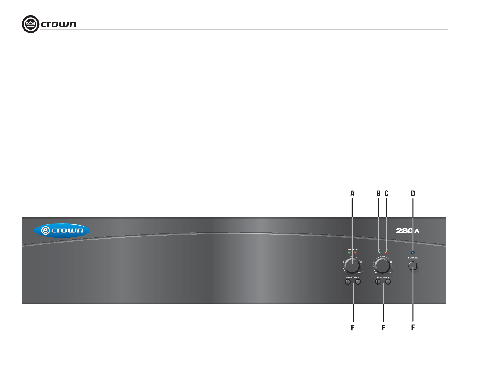
1.2 Front Panel Controls and Indicators
(280A shown; other models are fairly similar)
A. Master Volume Controls
One per output channel. Detented potentiometer with
knob.
B. Output Signal Presence Indicator
Green LED, one for each output channel, illuminates
when output signal level exceeds 100 mV (45 dB below
full power) from the 4-ohm tap.
C. Clip Indicator
Red LED, one per output channel, illuminates at threshold of audible distortion.
D. Power Indicator
Blue LED indicates power on.
E. Power Switch
Pushbutton on-off switch. The power switch does not
affect the 24V DC auxiliary power input (letter “H” on
next page).
F. Tone Controls
Bass and Treble non-detented potentiometers on each
channel. Bass ±10 dB at 100 Hz, Treble ±10 dB at 10
kHz.
page 6
Figure 1.1 Front Panel Controls and Indicators
(280A shown)
T
B
T
B
Operation Manual
Commercial Audio Series Amplifiers
1 Welcome
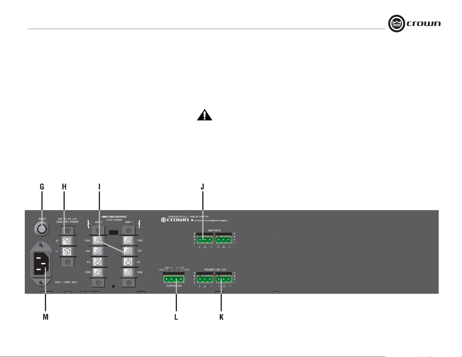
1.3 280A Back Panel Controls and Connectors
(180A and 1160A are fairly similar. See next
page for 660A).
J. Amp Input Connector
3-pin Phoenix-type, high-impedance balanced, one per amplifier channel.
G. Reset Switch
Resets the circuit breaker that protects the power supply. 220/
230/240V units have a fuse instead.
H. Auxiliary Power Input
2-position terminal strip for 24 VDC (±10%) backup power.
Accepts up to 10 AWG terminal forks. NOTE: To prevent a spark
when attaching a battery, have unit turned on and connected to
the mains supply.
I. Amplifier Outputs Connectors
One per channel, 4-position terminal strip with COM (Common), 4 ohms, 70V and 100V terminals. Accepts up to 10 AWG
terminal forks. Non-touch cover included.
K. Line Out Connector
One 3-pin balanced Phoenix-type connector per output channel.
Level controlled by master volume control.
L. Output VCA Connector
4-pin Phoenix-type connector for two VCA control lines of +10
VDC and ground. Compatible with Crown 1-VCAP and 4-VCAP
modules.
M. AC Power Inlet
Detachable IEC.
Operation Manual
Figure 1.2 Back Panel Controls and Connectors
(280A shown)
page 7
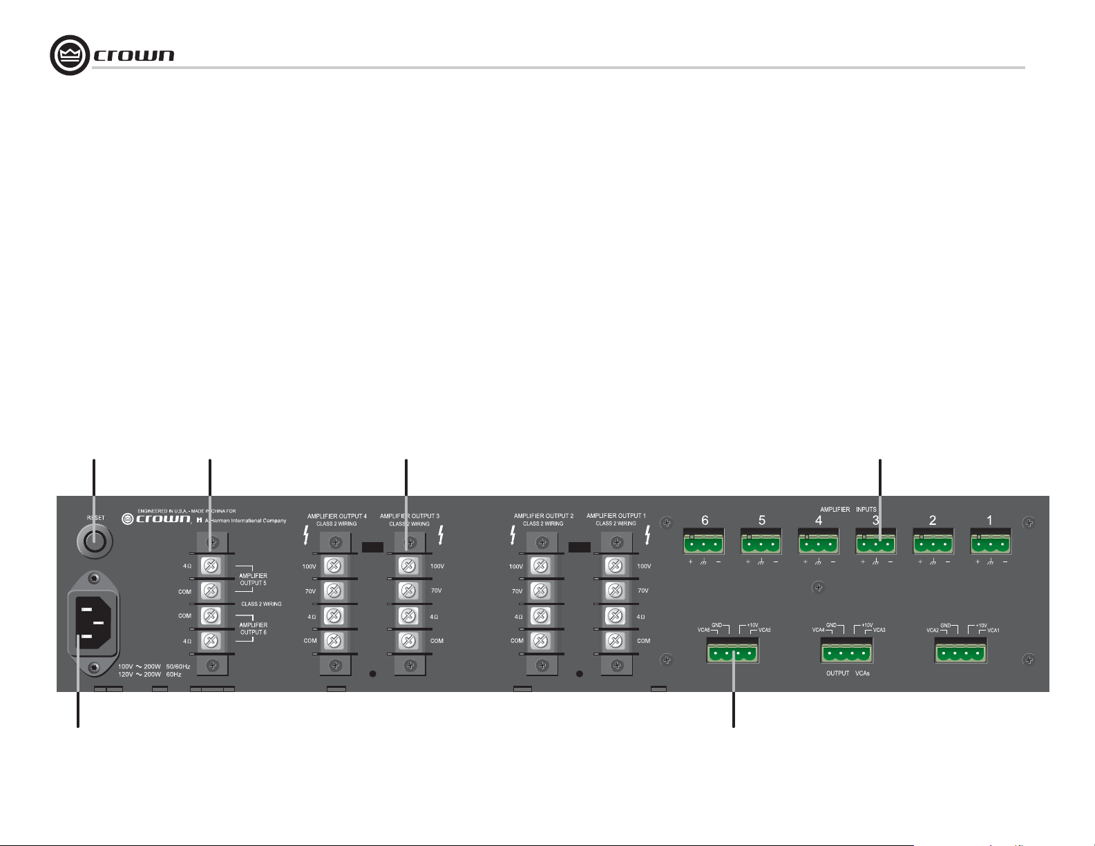
1 Welcome
1.4 660A Back Panel Controls and Connectors
A. Reset Switch
Resets the circuit breaker that protects the power supply. 220/
230/240V units have a fuse instead.
Commercial Audio Series Amplifiers
D. Amp Input Connector
3-pin Phoenix-type, high-impedance balanced, one per
amplifier channel.
E. AC Power Inlet
Detachable IEC.
B. Amplifier Outputs Connector
One 4-position terminal strip for channels 5 and 6 including
COM and 4-ohms terminals for each channel. Accepts up to
10 AWG terminal forks.
C. Amplifier Outputs Connectors
One connector per channel for channels 1-4 including COM,
4-ohms, 70V and 100V terminals. Accepts up to 10 AWG terminal forks.Non-touch cover included.
A
B
C
F. Output VCA Connector
One for every two channels, 4-pin Phoenix-type connector
for two VCA control lines of +10 VDC and ground. Compatible with Crown 1-VCAP and 4-VCAP modules.
D
E
page 8
F
Operation Manual
 Loading...