


YCEDX463RQ1
Crosley YCEDX463RQ1, IV87000, IV87001, IV86000, IV85000 Installation Instructions Manual
...
29IN.(73.7CM)ELECTRICDRYERINSTALLATION
INSTRUCTIONS
INSTRUCTIONSPOURL'INSTALLATIONDELASECHEUSE
ELECTRIQUEDE29PO (73,7CM)
TableofContents/Table desMati_res
DRYER SAFETY ............................................... 1
INSTALLAllON INSTRUCTIONS .................... 2
Tools and Parts ............................................. 2
Location Requirements ................................ 2
Electrical Requirements ................................ 3
Venting Requirements ................................... 4
Plan Vent System .......................................... 4
Install Vent System ........................................ 5
Install Leveling Legs ...................................... 6
Level Dryer .................................................... 6
Connect Vent ................................................. 6
Reverse Door Swing (Optional) ..................... 6
Complete Installation .................................... 7
S_CURIT_ DE LA SECHEUSE ........................ 8
INSTRUCTIONS D'INSTALLATION ................. 8
Outillage et pi_ces n_cessaires ..................... 8
Emplacement d'installation .......................... g
Installations _lectriques ............................... 10
Exigences concernant I'_vacuation ............. 11
Planification du syst_me d'_vacuation ........11
Installation du conduit d'_vacuation ............13
Installation des pieds de nivellement ........... 13
Mise _ niveau de la s_cheuse ...................... 13
Conduit d'_vacuation ................................... 14
Inversion de I'ouverture de la porte ............. 14
Achever I'installation .................................... 15
DRYERSAFETY
Your safety and the safety of others are very important.
We have provided many important sarety messages in this manual and on your appliance. Always read and obey all safety
messages.
This is the safety alert symbol.
This symbol alerts you to potential hazards that can kill or hurtyou and others.
All safety messages will follow the safety alert symbol and either the word "DANGER" or "WARNING."
These words mean:
You can be killed or serlousty Injured If you don't Immedlatel_
follow Instructions.
You can be killed or seriously Injured If you don't follow
Instructions.
All safety messages will tell you what the potential hazard is, tell you how to reduce the chance of injury, and tell you what can
happen if the instructions are not followed.
8535831
INSTALLATIONINSTRUCTIONS
ToolsandParts
Check that you have everything necessary for correct installation.
Proper installation is your responsibility.
a
a
a
a
fiat-blade screwdriver
adjustable wrench that
opens to 1 in. or hex-
head socket wrench (for
adjusting dryer feet)
level
#2 Phillips screwdriver
s safety glasses
= caulking gun and
compound (forinstalling
new exhaust vent)
= gloves
= tin snips (new vent
installations)
Parts supplied
Remove parts package from dryer drum. Check that all parts were
included.
4 leveling legs
Parts needed:
Check local codes, check existing electrical supply and venting
and see "Electrical Requirements" and "Venting Requirements"
before purchasing parts.
Mobile home installations require metal exhaust system hardware
available for purchase from the dealer from whom you purchased
your dryer. For further information, please reference the front page
of your "Dryer User Instructions."
LocationRequirements
Explosion Hazard
Keep flammable materials and vapors, such as
geaollne, away from dryer.
Place dryer at least 18 Inches (46 cm) above the floor
for a garage Installation,
Fallura to do so can result In death, explosion, or flra,
You will need
a A location that allows for proper exhaust installation. See
"Venting Requirements."
a A separate 30 amp circuit.
= A grounded electrical outlet located within 2 ft (61 cm) of
either side of the dryer. Sea "Electrical Requirements."
s A sturdy floor to support the total weight (dryer and load) of
200 Ib (90.7 kg).
s A level floor with a maximum slope of 1 in. (2.5 cm) under
entire dryer. (If slope is greater than 1 in. [2.5 cm], install
Extended Dryer Feet Kit, Part No. 279810.) Clothes may not
tumble properly and models with automatic sensor cycles
may not operate correctly if dryer is not level.
Do not operate your dryer at temperatures below 4,5°F(7°C). At
lower temperatures, the dryer might not shut off at the end of an
automatic cycle. Drying times can be extended.
Installthe dryer where it is protected from water and/or weather.
Check code requirements. Some codes limit, or do not permit,
installation of the dryer in garages, closets, mobile homes, or
sleeping quarters. Contact your local building inspector.
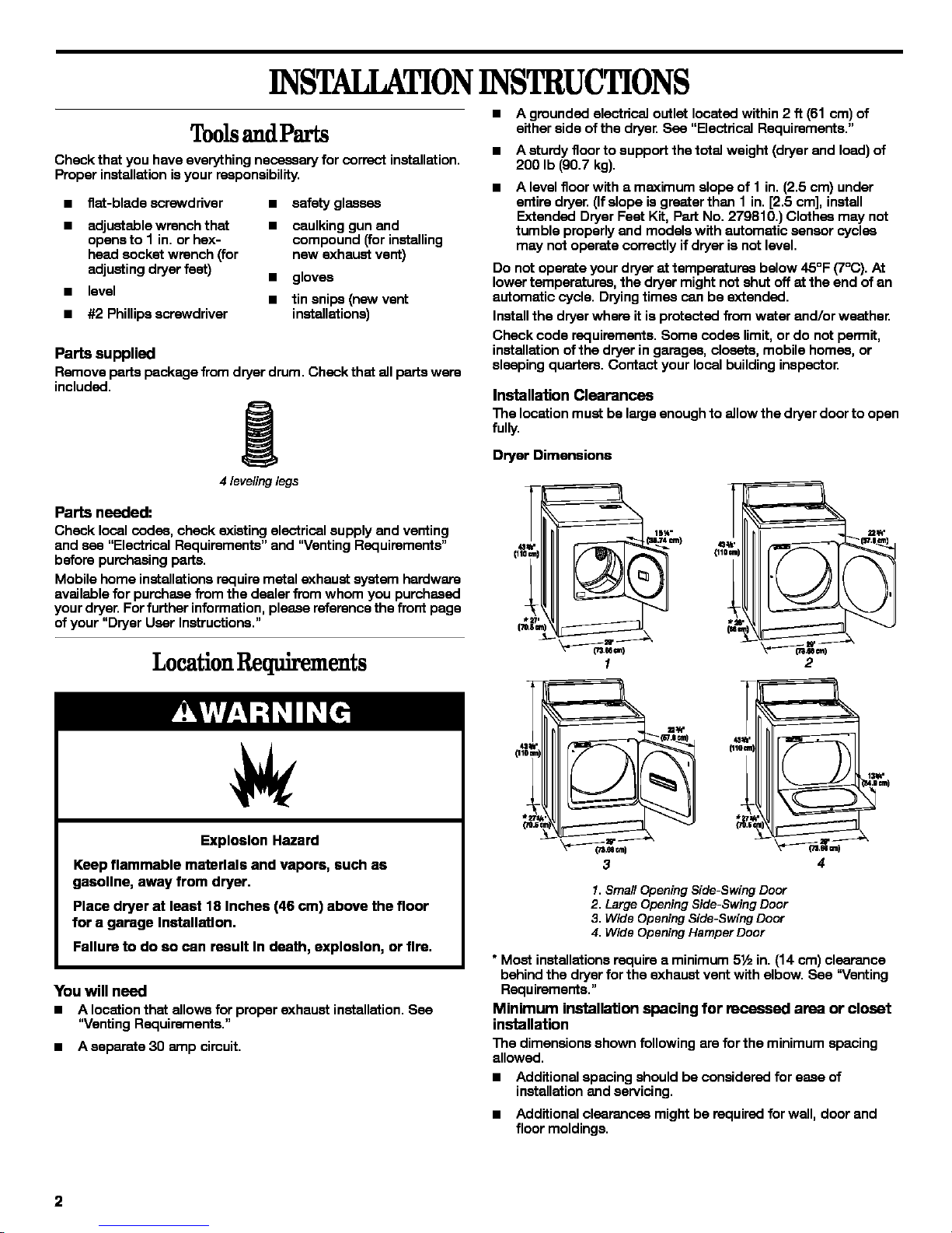
Installation Clearances
The location must be large enough to allow the dryer door to open
fully.
Dryer Dimensions
3
1. Small Opening Side-Swing Door
2. Large Opening Side-Swing Door
3. Wide Opening Side-Swing Door
4. Wide Opening Hamper Door
* Most installations require a minimum 5½ in. (14 cm) clearance
behind the dryer for the exhaust vent with elbow. See "Venting
Requirements."
Minimum installation spacing for receased area or closet
installation
The dimensions shown following are forthe minimum spacing
allowed.
s Additional spacing should be considered for ease of
installation and servicing.
a Additional clearances might be required for wall, door and
floor moldings.
2
• Additional spacing of 1 in. (2.5 cm) on all sides of the dryer is
recommended to reduce noise transfen
For closet installation, with a door, minimum ventilation
openings inthe top and bottom of the door are required.
Louvered doors with equivalent ventilation openings are
acceptable.
• Companion appliance spacing should also be considered.
m
olo
3
_3"
1.Recessed area
2. Side view - closet or confined area
3. Closet door with vents
Mobile Home-Additional Installation Requirements
This dryer is suitable for mobile home installations.The installation
must conform to the Canadian Manufactured Home Standard,
CAN/CSA-Z240 MH.
Mobile home installations require:
• Metal exhaust system hardware which is available for
purchase from your dealer.
Special pmvialons must be made in mobile homes to
introduce outside air into the dryeE The opening (such as a
nearby window) should be st least twice as large as the dryer
exhaust opening.
FAeetri qulrements
Electrical Shock Hazard
Plug Into a grounded 4 prong outlet.
Failure to do so can result In death or electrical shock.
It is your responsibility
• Tocontacta qualifiedelectricalinstaller,
• To be sure that the electrical connection is adequate and in
conformance with the Canadian Electrical Code, C22.1-1atest
edition and all local codes. A copy ofthe above codes
standard may be obtained from: Canadian Standards
Association, 178 Rexdals Blvd., Toronto, ON Mgw 1R3
CANADA.
• A 4 wire, single phase, 115/230-volt, 60-Hz., AC-only
electrical supply is required on a separate 30-amp circuit,
fused on both sides of the line. A time-delay fuse or circuit
breaker is recommended. Connect to an individual branch
circuit.
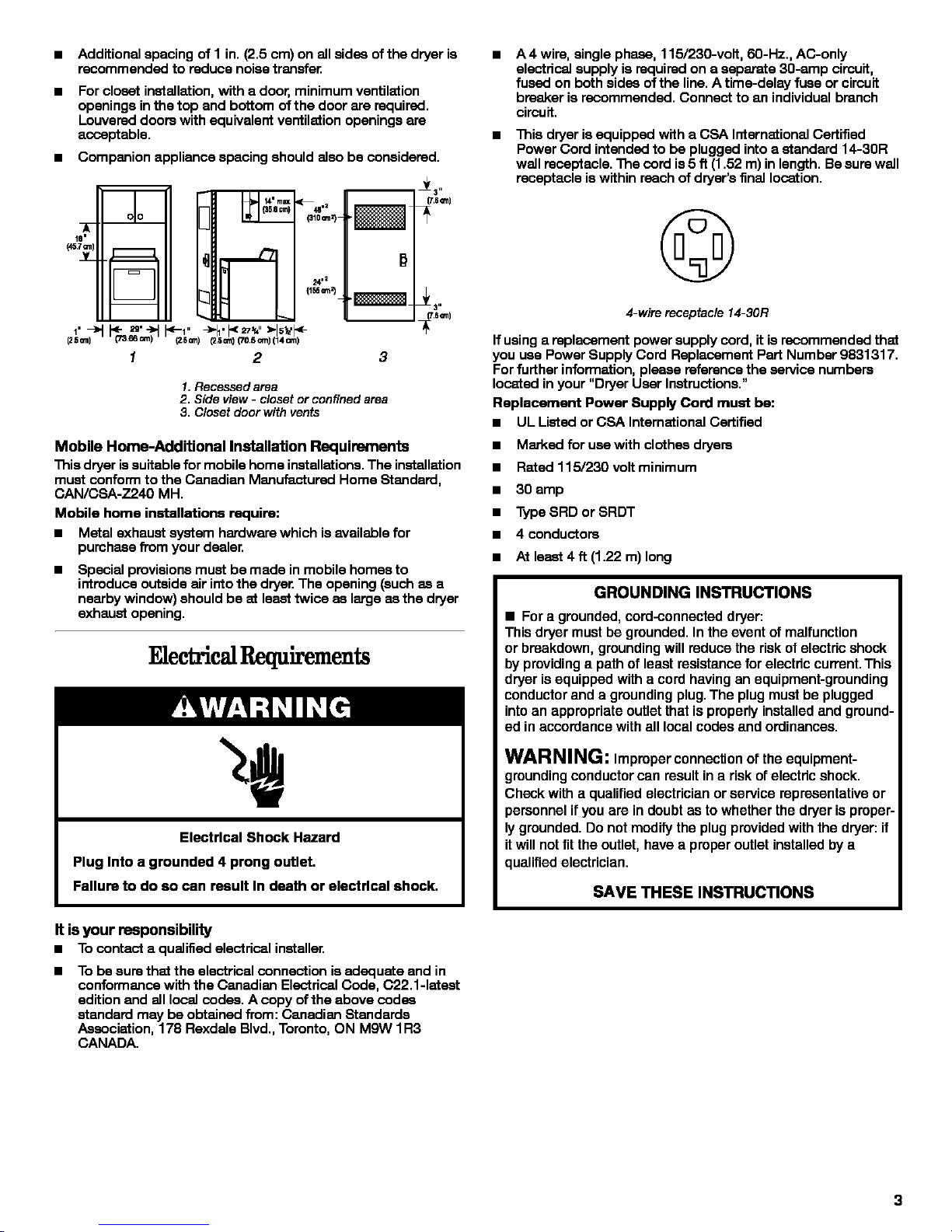
• This dryeris equipped with a CSA International Certified
Power Cord intended to be plugged into a standard 14-30R
wall receptacle. The cord is 5 ft (1.52 m) in length. Be sure wall
receptacle is within reach of dryer's final location.
©
4-wire receptacle14-30R
If using a replacement power supply cord, it is recommended that
you use Power Supply Cord Replacement Part Number 9831317.
Forfurther information, please reference the service numbers
located in your "Dryer User Instructions."
Replacement Power Supply Cord must be:
• UL Listed or CSA International Certified
• Marked for use with clothes dryers
• Rated 115/230 voltminimum
• 30 amp
• Type SRD or SRDT
• 4 conductors
• At least 4 ft (1.22 m) long
GROUNDING INSTRUCTIONS
• For a grounded, cord-connected dryer:
This dryer must be grounded. In the event of malfunction
or breakdown, grounding will reduce the risk of electric shock
by providing a path of least resistance for electric current. This
dryer is equipped with a cord having an equipment-grounding
conductor and a grounding plug. The plug must be plugged
into an appropriate outlet that is properly installed and ground-
ed in accordance with all local codes and ordinances.
WARNING: Improper connection or the equipment-
grounding conductor can result in a risk ofelectric shock.
Check with a qualified electrician or service representative or
personnel ir you are in doubt as to whether the dryer is proper-
ly grounded. Do not modify the plug provided with the dryer: if
it will not fitthe outlet, have a proper outlet installed by a
qualified electrician.
SAVE THESE INSTRUCTIONS
VentingRequirements PlanVentSystem
Fire Hazard
Use a heavy metal vent.
Do not use a plaatlc vent.
Do not use a metal foil vent.
Failure to follow these Inatructlone can result In death
or fire.
WARNING: To reduce the risk of fire, this dryer MUST BE
EXHAUSTED OUTDOORS.
4 in. (10.2 cm) heavy metal exhaust vent and clamps must be
used. DURASAFE TM venting products are recommended.
DURASAFETM vent products can be purchased from your dealer
or by calling Whirlpool Parts and Accessories. For more
information, see the "Assistance or Service" section of your
"Dryer User Instructions."
• Do not exhaust the dryer into any gas vent, chimney, wall,
ceiling, or a concealed space of a building.
• Do not use an exhaust hood with a magnetic latch.
• Do not installflexible metal vent in enclosed walls, ceilings or
floors.
• Do not use screws or ether fastening devices that extend into
the interior of the vent to secure vent.
IMPORTANT: Observe all governing codas and ordinances.
Improper venting can cause moisture and lint to collect
Indoors, which may result In:
• Moisture damage to woodwork, furniture, paint, wall-
paper, carpets, etc.
• Housecleaning problems and health problems.
Use a heavy metal vent. Do net use plastic or metal foil vent.
Rigid metal vent is recommended to prevent crushing and kinking.
Flexible metal vent must be fully extended and supported when
the dryer is in its final position. Remove excess flexible metal vent
to avoid sagging and kinking that may result in reduced airflow
and poor performance.
An exhaust hood should cap the vent to prevent rodents and
insects from entering the home.
Exhaust hood must be at least 12 in. (30.5 cm) from the ground or
any object that may be inthe path of the exhaust (such as flowers,
rocks or bushes, etc.).
If using an existing vent system, clean lintfrom the entire length of
the system and make sure exhaust hood is not plugged with lint.
Replace any plastic or metal foilvent with rigid metal or flexible
metal vent.
Use clamps to seal all joints. Do not use duct tape, screws or
ether fastening devices that extend into the interior ofthe vent to
eacure vent.
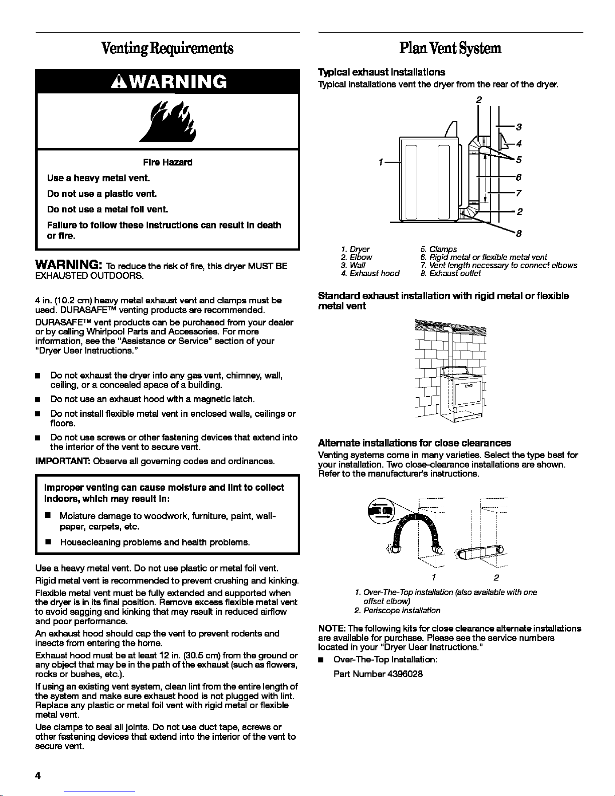
Typical exhaust installations
Typicalinstallationsventthe dryerfromtherearofthe dryer,
1 m
2
1. Dryer
2. Elbow
3. Wail
4. Exhaust hood
5. Clamps
6. Rigid metal or flexible metal vent
7, Vent length necessary to connect elbows
8, Exhaust outlet
Standard exhaust installation with rigid metal or flexible
metal vent
Altemate installations for close clearances
Venting systems come in many varieties. Select the type best for
your installation. Two close-clearance installations are shown.
Referto the manufacturer's instructions.
1 2
1. Over- The- Top installation (also available with one
offset elbow)
2. Periscope installation
NOTE: The following kits for close clearance alternate installations
are available for purchase. Please see the service numbers
located in your "Dryer User Instructions."
• Over-The-Top Installation:
Part Number 4396028
4
• Periscope Installation (For use with dryer vent to wall vent
mismatch):
Part Number 4396037 - 0 in. (0 cm) to 18 in. (45.72 cm)
mismatch
Part Number 4396011 - 18 in. (45.72 cm)to 29 in. (73.66 cm)
mismatch
Part Number 4396014 - 29 in. (73.66 cm)to 50 in. (127 cm)
mismatch
Special provisions for mobile home installations
The exhaust vent must be securely fastened to a noncombustible
portion of the mobile home structure. Do not use screws or other
fastening devices that extend intothe interiorof the vent to secure
vent.
Terminate the exhaust vent outside. The exhaust vent must not
terminate beneath the mobile home and must not be connected
to any other duct, vent or chimney.
Determine Vent Length
1. Select the route that will provide the straightest and most
direct path outdoors. Plan the installation to use the fewest
number of elbows and turns. When using elbows or making
turns, allow as much room as possible. Bend vent graduallyto
avoid kinking. Avoid 90° turns.
2. Determine vent length.
The maximum length ofthe exhaust system depends upon:
• The type ofvent (rigid metal or flexible metal).
• The number of elbows used.
• Type of hood.
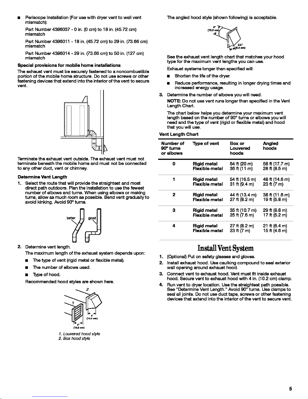
Recommended hood styles are shown here.
_2
_o=©m)
1.Louvered hood style
2. Box hoodstyle
3,
The angled hood style (shown following) is acceptable.
°°
See the exhaust vent length chart that matches your hood
type for the maximum vent lengths you can use.
Exhaust systems longer then specified will:
• Shorten the life of the drye_
• Reduce performance, resulting in longer drying times and
increased energy usage.
Determine the number of elbows you will need.
NOTE: Do not use vent runs longer than specified inthe Vent
Length Chart.
The chart below helps you determine your maximum vent
length based on the number of 90° turns or elbows you will
need and the type of vent (rigidor flexible metal) and hood
that you will use.
Vent Length Chart
Number of Type of vent Box or Angled
90° turns Louvered hoods
or elbows hoods
O Rigid metal 64 ft (20 m) 58 _ (17.7 m)
Flexible metal 36 ft (11 m) 28 _ (8.5 m)
1 Rigid metal 54 ft (16.5 m) 48 _ (14.6 m)
Flexible metal 31 ft (9.4 m) 23 _ (7m)
2 Rigid metal 44 ft (13.4 m) 38 _ (11.6 m)
Flexible metal 27 ft (8.2 m) 19 _ (5.8 m)
3 Rigid metal 35 ft (10.7 m) 29 _ (8.8 m)
Flexible metal 25 ft (7.6 m) 17 _ (5.2 m)
4 Rigid metal 27 ft (8.2 m) 21 _ (6.4 m)
Flexible metal 23 ft (7 m) 15 _ (4.6 m)
InstallVentSystem
1. (Optional) Put on safety glasses and gloves.
2. Install exhaust hood, Use caulking compound to seal exterior
wall opening around exhaust hood,
3. Connect vent to exhaust hood, Vent must fit inside exhaust
hood, Secure vent to exhaust hood with 4 in, (10,2 cm) clamp,
4. Run vent to dryer location, Use the straightest path possible,
See "Determine Vent Length," Avoid 90° turns, Use clamps to
seal all joints. Do not use duct tape, screws or other fastening
devices that extend into the interior ofthe vent to secure vent.
 Loading...