


CA-12
PROFESSIONAL POWER AMPLIFIERS
Professional Power Amplifier
Professional Power Amplifier
Professional Power Amplifier
Professional Power Amplifier
Professional Power Amplifier
Professional Power Amplifier
OWNER’ S MANUAL

Important Precautions
This symbol is used to alert the operator to follow important operating
procedures and precautions detailed
in documentation.
This symbol is used to warn operators that uninsulated “dangerous voltages” are present within the equipment enclosure that may pose a risk
of electric shock.
1. Save the carton and packing material
even if the equipment has arrived in
good condition. Should you ever need
to ship the unit, use only the original
factory packing.
2. Read all documentation before operating your equipment. Retain all doc-
umentation for future reference.
3. Follow all instructions printed on unit
chassis for proper operation.
4. Do not spill water or other liquids
into or on the unit, or operate the unit
while standing in liquid.
5. Make sure power outlets conform to
the power requirements listed on the
back of the unit.
6. Do not use the unit if the electrical
power cord is frayed or broken. The
power supply cords should be routed so
that they are not likely to be walked on
or pinched by items placed upon or
against them, paying particular attention to cords and plugs, convenience
receptacles, and the point where they
exit from the appliance.
7. Always operate the unit with the AC
ground wire connected to the electrical system ground. Precautions should
be taken so that the means of grounding of a piece of equipment is not
defeated.
8. Mains voltage must be correct and
the same as that printed on the rear
of the unit. Damage caused by connec-
tion to improper AC voltage is not covered by any warranty.
10. Power down & disconnect units from
mains voltage before making connections.
11. Never hold a power switch in the
“ON” position if it won’t stay there
itself!
12. Do not use the unit near stoves, heat
registers, radiators, or other heat
producing devices.
13. Do not block fan intake or exhaust
ports. Do not operate equipment on a
surface or in an environment which
may impede the normal flow of air
around the unit, such as a bed, rug,
weathersheet, carpet, or completely
enclosed rack. If the unit is used in an
extremely dusty or smoky environment, the unit should be periodically
“blown free” of foreign matter.
14. Do not remove the cover. Removing
the cover will expose you to potentially
dangerous voltages. There are no user
serviceable parts inside.
15. Connecting amplifier outputs to
oscilloscopes or other test equipment
while the amplifier is in bridged mode
may damage both the amplifier and test
equipment!
16. Do not drive the inputs with a signal
level greater than that required to
drive equipment to full output.
17. Do not connect the inputs / outputs
of amplifiers or consoles to any other
voltage source, such as a battery,
mains source, or power supply, regardless of whether the amplifier or console
is turned on or off.
18. Do not run the output of any amplifi-
er channel back into another channel’s input. Do not parallel- or
series-connect an amplifier output
with any other amplifier output.
Crest Audio is not responsible for damage to loudspeakers for any reason.
20. Non-use periods. The power cord of
equipment should be unplugged from
the outlet when left unused for a long
period of time.
21. Service Information Equipment
should be serviced by qualified service
personnel when:
A. The power supply cord or the plug
has been damaged;
B. Objects have fallen, or liquid has
been spilled into the equipment;
C. The equipment has been exposed to
rain;
D. The equipment does not appear to
operate normally, or exhibits a
marked change in performance;
E. The equipment has been dropped,
or the enclosure damaged.
22. To obtain service, contact your nearest
Crest Audio Service Center,
Distributor, Dealer, or Crest Audio at
201.909.8700 (USA).
9. Have gain controls on amplifiers
turned down during power-up to prevent speaker damage if there are high
signal levels at the inputs.
19. Do not ground any red (“hot”) ter-
minal. Never connect a “hot” (red)
output to ground or to another “hot”
(red) output!

Power Amplifier Owner’s Manual
Table of Contents
Introduction
Unpacking
Installation and Mounting
Front Panel
Rear Panel
Internal Configuration and Control
Operation
Connecting Power / Circuit Size Requirements
Cooling Requirements
Connecting Inputs
Connecting Outputs
Mode Selection
Stereo /Parallel/Bridged Mono Connections
TourClass®Protection Features
User Precautions
Speaker Protection
Recommended Speaker Cabling
Maintenance
User Responsibility
Service and Repair
5
5
5
6
7
8
9
9
9
10
10
10
12
14
15
15
15
16
16
16
Appendix A Specifications
Appendix B CA Block Diagram
Appendix C Wire Gauge Charts
Appendix D Rear Panel Symbols - Legend
Appendix E CA18 Power Amplifier - Special Functions
Crest Audio CA Series Power Amplifiers Page 3
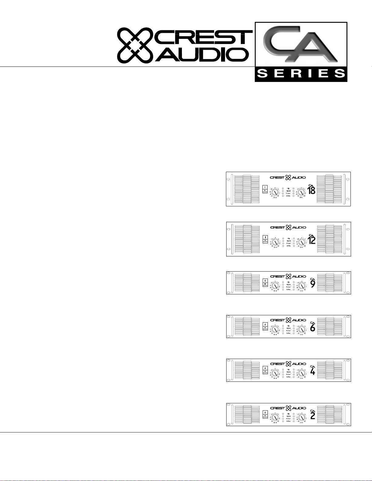
Models CA2, CA4, CA6, CA9, CA12, CA18
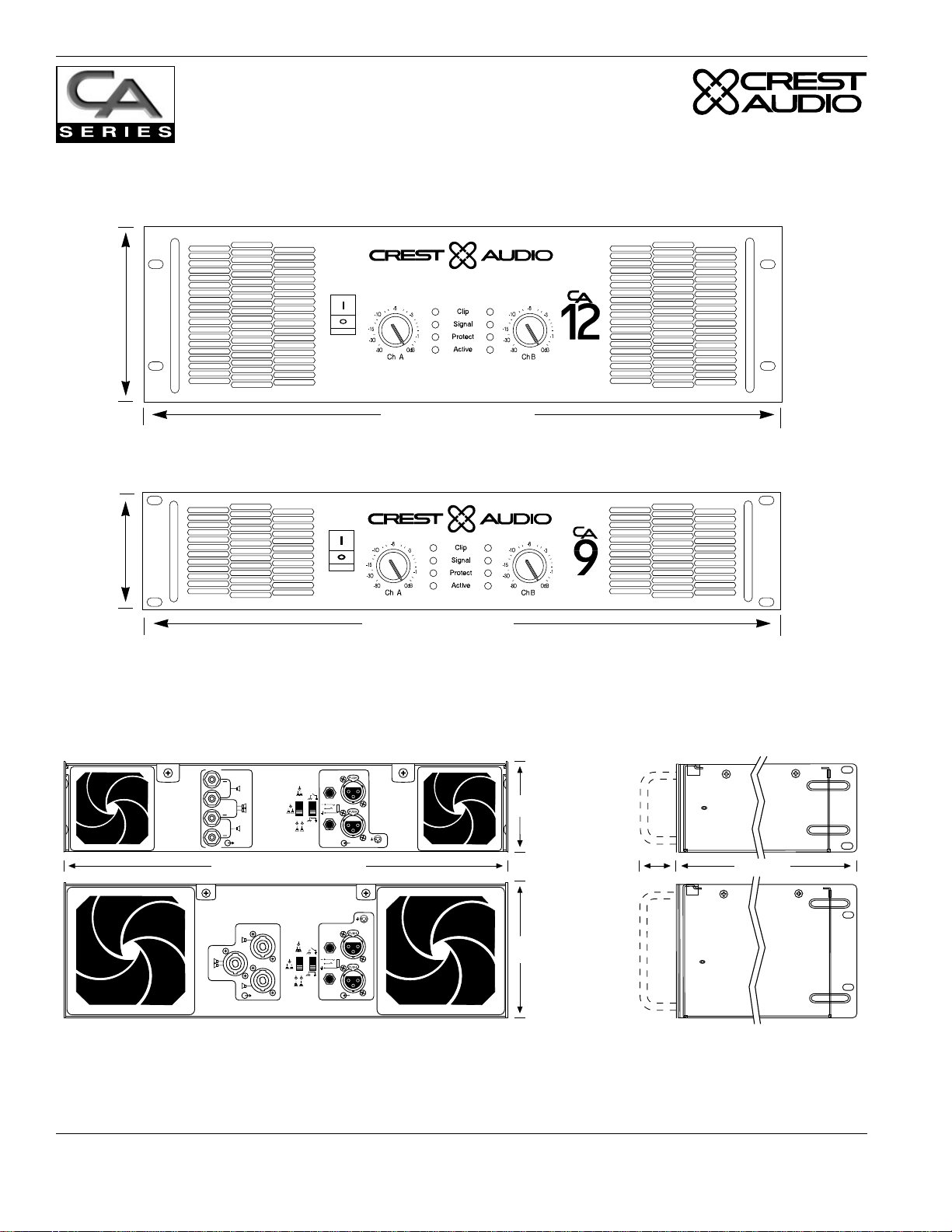
Front
height
5.25"
133mm
Front
height
3.5"
89mm
CA12, CA18 Front View
Professional Power Amplifier
Front width 19" / 483mm
CA2-9 Front View
Professional Power Amplifier
Front width 19" / 483mm
Rear & Side Views
3.5"
89mm
5.25"
133mm
CA2
CA4
CA2-9
CA6
CA9
5-way binding post
version shown.
CA12
CA18*
CA12
CA18
Speakon version
shown.
1.375"
35mm
18"/457mm
A
A
+
+
A
B
+
B
A
•
•
AB
A
+
A
B
••
A
B
B
A
B
17.9"/437mm (19"/483mm to rack ears)
A
A
A
B
B
A
•
•
AB
A
+
A
B
••
A
B
B
A
B
2+
1
3-
2+
1
3-
*Note: see Appendix E for detailed CA18 rear panel drawings.
Page 4 Crest Audio CA Series Power Amplifiers
Models CA2, CA4, CA6, CA9, CA12, CA18

Introduction
Congratulations on your purchase of a new CA Series professional power amplifier, and thank you for your
confidence in Crest Audio products. You are among the growing number of audio professionals who have
made Crest Audio one of the world’s leading suppliers of professional and commercial/industrial audio systems.
For your safety, please read the Important Precautions section before installing and operating the amplifier.
The Crest Audio CA Series is based on the same advanced circuit topologies that have made Crest ampli-
fiers the choice of touring professionals worldwide. CA Series amplifiers are designed for high operating
efficiency and accurate sonic performance across the full audio bandwidth, even under stressful conditions.
In order to maintain strict quality assurance standards, all CA Series amplifiers are built in Crest’s state-ofthe-art USA manufacturing facility. Internal components are the finest available, and key sub-assemblies are
pre-tested before final assembly. Finally, each amplifier is “burned in” and thoroughly tested (using precision audio test equipment) before shipping. In addition, all CA Series amplifiers incorporate Crest’s exclusive TourClass protection features to safeguard both internal circuitry and connected loudspeakers.
This proven combination of advanced design, quality construction, and comprehensive circuit protection is
your guarantee of fail-safe reliability. You can depend on consistent, stable performance even when your
CA Series amplifier is subjected to punishing extremes in the most demanding fixed or mobile sound reinforcement applications.
Unpacking
Please inspect the amplifier carefully immediately after unpacking. If you find any damage, notify your supplier/dealer immediately. Only the shipper may file a damage claim with the carrier for damage incurred
during shipping. Be sure to save the carton and all packing materials for the carrier’s inspection.
If your packing materials are in good condition, please save them. If you ever need to ship the unit back to
Crest Audio or an authorized service center, you should use only the original factory packing.
Installation and Mounting
Four CA Series amplifiers are 2-rack-space units: models CA2, CA4, CA6, and CA9. Models CA12 and
CA18 are 3-rack-spaces high. All mount in standard 19-inch racks. Four front-panel mounting holes are
provided on each amplifier. Rear mounting ears give additional support, and use of rear supports is highly
recommended in all mobile and touring sound systems. Optional rack-mount handles are available.
Crest Audio CA Series Power Amplifiers Page 5
Models CA2, CA4, CA6, CA9, CA12, CA18
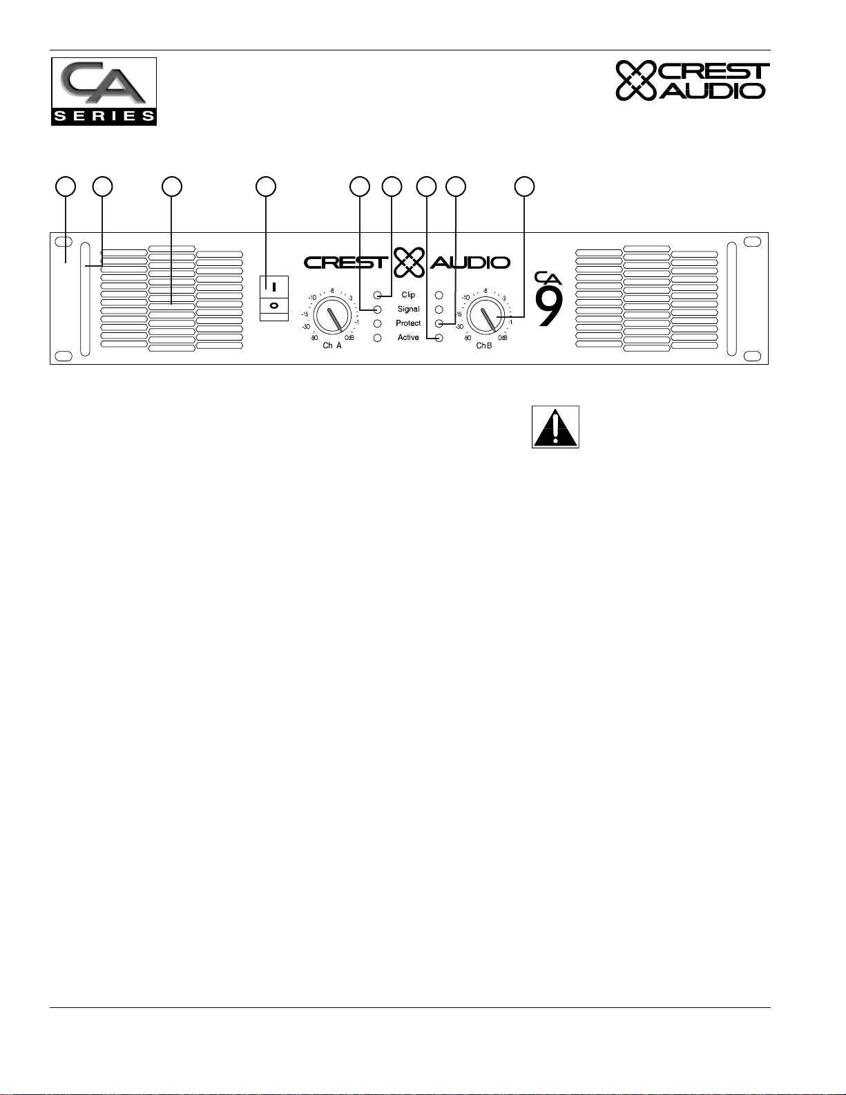
Front Panel
2 3 54 6
1
Professional Power Amplifier
1. Rack Mounting Ears.
Two front panel mounting holes are provided on each mounting ear.
2. Optional Rack Handles.
7 8 9
Never try to hold the
circuit breaker/power
switch in the “ON”
position if it won’t stay
Available from your authorized Crest Audio supplier.
there itself!
3. Fan Outlet Grills.
CA Series amplifiers are cooled by two, rear-mounted fans. Cool air flows over the heat sinks and exhausts
through the front grills. Make sure these outlets remain clear to allow unrestricted air flow.
4. AC Power Switch/Circuit Breaker.
CA Series amplifiers have a front-panel combination AC switch and circuit breaker. (No fuses are used.) If
the switch shuts off during normal use, push it back to the “ON” position once. If it will not stay on, the
amplifier needs servicing.
5. Signal LED.
Illuminates to indicate that a signal (above a minimum threshold) is present at the amplifier input, and that
the signal is being amplified.
6. Clip LED.
Illuminates at the clipping threshold. Continuous illumination also indicates that ACL (Active Clip
Limiting) protection circuitry is engaged.
7. Active LED.
Indicates that AC power is connected and the amplifier is turned on.
8. Protect LED.
Indicates that the channel is in Protect mode (speakers disconnected by output relay).
9. Input Attenuators.
Two input attenuators adjust level for their respective amplifier channels. In Bridged Mono Mode, both
attenuators are used to control signal level and must be adjusted to the same setting.
Page 6 Crest Audio CA Series Power Amplifiers
Models CA2, CA4, CA6, CA9, CA12, CA18
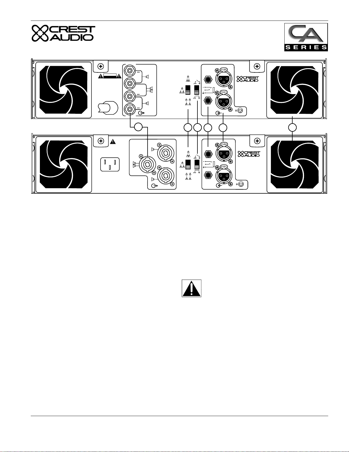
Rear Panel See Appendix E for information specific to model CA18.
CAUTION
RISK OF ELECTRIC SHOCK
DO NOT OPEN
AVIS : RISQUE DE CHOC ÉLECTRIQUE—NE PAS OUVRIR
WARNING TO REDUCE THE RISK OF FIRE OR ELECTRIC SHOCK DO NOT
EXPOSE THIS EQUIPMENT TO RAIN OR MOISTURE.
ATTENTION! POUR ÉVITER LE RISQUE D'INCENDIE OU DE CHOC
ÉLECTRIQUE, NE PLACEZ PAS CET APPAREIL SOUS LA PLUIE OU Á
L'HUMIDITÉ
A
A
B
A
A
B
A
AB
A
B
B
A
11 12
A
AB
B
A
B
A
A
+
+
A
B
+
B
10
NL4FC
A
A
B
B
A
•
•
+
••
B
13
A
•
•
+
•
•
B
14
Designed & manufactured in the USA by:
Crest Audio Inc.
100 Eisenhower Dr.
Paramus, New Jersey 07652 USA
2+
1
3-
643-105
Designed & manufactured in the USA by:
Crest Audio Inc.
100 Eisenhower Dr.
Paramus, New Jersey 07652 USA
2+
1
3-
15
10. Output Connectors (Two versions, market dependent)
CA Series amplifiers are supplied with either 5-way Binding Posts or Speakon connectors. Connection to
the binding posts can be made with bare wire, banana plugs, or spade lug terminations. Make connections to
both the Channel A and Channel B terminals for Stereo or Parallel Mode, or a single connection across the
red (“hot”) terminals only of Channels A and B for Bridged Mono Mode. Using Speakon-type speaker
cables, make connections to both the Channel A and Channel B connectors for Stereo or Parallel Mode, or
to the Bridged mode connector for Bridged Mono Mode. See Appendix D and the section on Mode
Selection for more information. NOTE: on the 5-way Output Binding Post version of the CA18, two pairs
of 5-way binding posts are provided for each channel, so that paralleling of speakers is possible.
11. Mode Selection Switch.
This recessed, three-position switch configures the
Never connect a “hot” (red) output to ground
or to another “hot” (red) output!
amplifier for Stereo, Parallel or Bridged Mono Mode operation. Amplifiers are factory-configured for
Stereo Mode. See Appendix D and the section on Mode Selection for more information.
12. Signal Ground Lift Switch.
The recessed signal ground lift switch (factory-set to the ‘ground’ [bottom] position) electrically connects
signal ground to the chassis/AC ground. The top position lifts the amplifier’s signal ground. In a properly
designed system (for safety purposes and to minimize noise), amplifiers should be connected to ground
through the AC line cord. Also, whenever possible, the signal source equipment should share the same AC
ground as the amplifier. In some cases this may not be possible, and a ground loop results. If this happens,
the first step is to move the ground lift switch to the top (‘lift’) position. In this position, the signal ground is
lifted and completely isolated from the chassis/AC ground. Do not change the switch to the ‘lift’ position if
the amplifier and the signal source equipment are on the same AC ground. Should the ground loop problem
persist after the ground lift switch has been set to the ‘lift’ position, then the shield on balanced input lines
should be grounded at one end only (usually the signal source).
Crest Audio CA Series Power Amplifiers Page 7
Models CA2, CA4, CA6, CA9, CA12, CA18
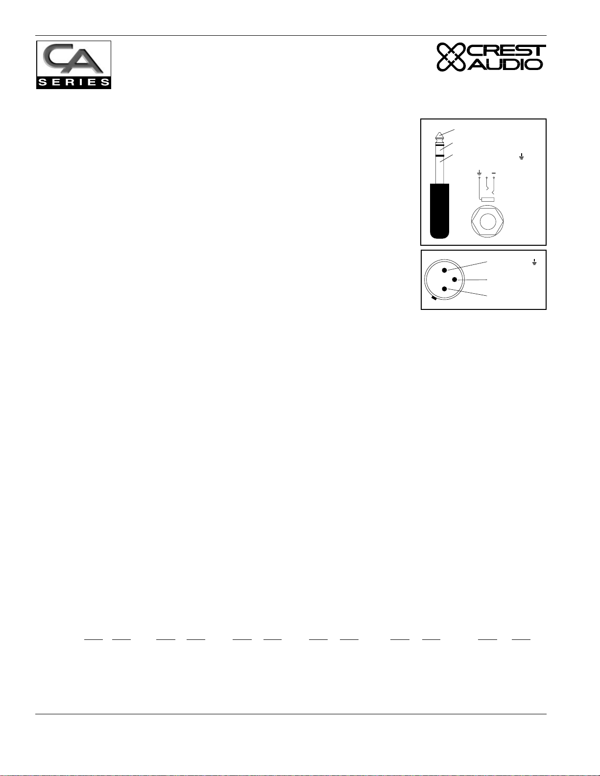
13-14. Balanced 1/4" (TRS) & XLR Input Connectors.
These connectors accept input signals on balanced TRS and XLR input plugs.
See the figure at the left for information on polarity. Connectors for each channel are in parallel; the unused connectors may be used for “loop through” con-
Tip - Positive (+)
Ring - Negative (-)
Sleeve - Ground ( )
+
nection to other amplifiers.
NOTE: Unbalanced “Tip/Sleeve” plugs may be used with the balanced TRS
“Tip/Ring/Sleeve” connectors. The “ring” terminal or negative input will be
connected to ground internally. When using three-pole (‘stereo’) TRS connectors, make sure that the ring connection is made either to the cold (–) output of
1 - Ground ( )
the source equipment, or to ground. Incorrect connections may cause a 6dB loss
in level.
3 - Negative (-)
2 - Positive (+)
15. Fan Inlet Ports & Filters.
Cooling air enters the amplifier through the fan inlet ports located on the rear of the amplifier chassis.
Be sure not to block these ports when installing the amplifier or other associated equipment. Air must flow
unimpeded through these ports. Fan filters (removable without tools) are provided to minimize entry of dust
and dirt.
Internal Configuration and Control
Input XLR Polarity
CA Series amplifiers are supplied standard with the XLR configured as “Pin 2 hot” (+). On models CA2,
CA4, CA6, CA9 and CA12, an internal jumper makes it possible to alter the amplifier to “Pin 3 hot” (+).
NOTE: This jumper is NOT user configurable. Please consult your supplier or local Crest Audio service
center if you wish to have the input XLR polarity changed
On the CA18, an external XLR polarity switch is featured. (See Appendix E).
Input Sensitivity
The CA Series amplifiers have a standard input sensitivity of .775 Volts for rated power at 8 Ohms. Models
CA2, CA4, CA6, CA9 and CA12 are fitted with an internal jumper which allows optional gains of X20 or
X40. Model CA18 features an external voltage gain/input sensitivity switch (See Appendix E). Standard
and optional voltage gains/input sensitivities are detailed below.
CA2 CA4 CA6 CA9 CA12 CA18
Gain Sens Gain Sens Gain Sens Gain Sens Gain Sens Gain Sens
Std. X45 .775V X61 .775V X68 .775V X86.5 .775V X97.5 .775V X115 .775V
Opt. 1 X40 .866V X40 1.12V X40 1.32V X40 1.66V X40 1.87V X40 2.24V
Opt. 2 X20 1.73V X20 2.24V X20 2.65V X20 3.32V X20 3.74V X20 4.47V
NOTE: This jumper is NOT user configurable. Please consult your supplier or local Crest Audio service
center if you wish to have the voltage gain / input sensitivity changed.
Page 8 Crest Audio CA Series Power Amplifiers
Models CA2, CA4, CA6, CA9, CA12, CA18
 Loading...