


owner’s manual
X-Rack rack mount mixers
XR-20
XR-24

Important precautions
XR-20 / XR-24 owner’s manual
1 |
Save the carton and packing materials! |
||
|
Should you ever need to ship the unit, |
||
|
use only the original factory packing. |
||
|
For replacement packaging, call Crest Audio’s |
||
|
Customer Service Department directly. |
||
2 |
Read all documentation before |
||
|
operating your equipment. Retain all |
||
|
documentation for future reference. |
||
3 |
Follow all instructions printed on |
||
|
unit chassis for proper operation. |
||
4 |
|
|
|
Do not use the unit if the electrical |
|||
|
power cord is frayed or broken. |
||
|
The power supply cord should be rout- |
||
|
ed so that it is not likely to be walked on |
||
|
or pinched by items placed upon or |
||
|
against it. |
||
5 |
Always operate the unit with the |
||
|
AC ground wire connected to the |
||
|
electrical system ground. Precautions |
||
|
should be taken so that the means of |
||
|
grounding of a piece of equipment is not |
||
|
defeated. |
||
6 |
Damage caused by connection to |
||
|
improper AC voltage is not covered |
||
|
by any warranty. |
||
7 |
Do not spill water or other liquids |
||
|
into or on the unit, or operate the |
||
|
unit while standing in liquid. |
||
8 |
The power cord of equipment |
||
|
should be unplugged from the out- |
||
|
let when left unused for a long peri- |
||
|
od of time. |
||
Service Information
Do not open unit!
Opening the unit will expose you to
potentially dangerous voltages. There are
no user serviceable parts inside.
Equipment should be serviced by
qualified service personnel when:
A.The equipment has been exposed to rain.
B.The equipment does not appear to operate normally, or exhibits a marked change in performance.
C.The equipment has been dropped, or the enclosure damaged.
To obtain service:
contact your nearest Crest Audio Service Center, Distributor, Dealer, or Crest Audio at 201.909.8700 USA or visit www.crestaudio.com for additional information.
email techserve@crestaudio.com
This symbol is used to alert
the operator to follow important procedures and precautions detailed in documentation.
This symbol is used to warn operators that uninsulated “dangerous voltages” are present within the equipment enclosure that may
pose a risk of electrical shock.

IMPORTANT SAFETY INSTRUCTIONS
WARNING: When using electrical products, basic cautions should always be followed, including the following:
1.Read these instructions.
2.Keep these instructions.
3.Heed all warnings.
4.Follow all instructions.
5.Do not use this apparatus near water.
6.Clean only with a dry cloth.
7.Do not block any of the ventilation openings. Install in accordance with manufacturer’s instructions.
8.Do not install near any heat sources such as radiators, heat registers, stoves or other apparatus (including amplifiers) that produce heat.
9.Do not defeat the safety purpose of the polarized or grounding-type plug. A polarized plug has two blades with one wider than the other. A grounding type plug has two blades and a third grounding plug. The wide blade or third prong is provided for your safety. If the provided plug does not fit into your outlet, consult an electrician for replacement of the obsolete outlet.
10.Protect the power cord from being walked on or pinched, particularly at plugs, convenience receptacles, and the point they exit from the apparatus.
11.Only use attachments/accessories provided by the manufacturer.
12.Use only with a cart, stand, tripod, bracket, or table specified by the manufacturer or sold with the apparatus. When
a cart is used, use caution when moving the cart/apparatus combination to avoid injury from tip-over.
13.Unplug this apparatus during lightning storms or when unused for long periods of time.
14.Refer all servicing to qualified service personnel. Servicing is required when the apparatus has been damaged in any way, such as power-supply cord or plug is damaged, liquid has been spilled or objects have fallen into the apparatus, the apparatus has been exposed to rain or moisture, does not operate normally, or has been dropped.
15.Never break off the ground pin. Write for our free booklet “Shock Hazard and Grounding.” Connect only to a power supply of the type marked on the unit adjacent to the power supply cord.
16.If this product is to be mounted in an equipment rack, rear support should be provided.
17.Exposure to extremely high noise levels may cause a permanent hearing loss. Individuals vary considerably in susceptibility to noise-induced hearing loss, but nearly everyone will lose some hearing if exposed to sufficiently intense noise for a sufficient time. The U.S. Government’s Occupational and Health Administration (OSHA) has specified the following permissible noise level exposures:
Duration Per Day In Hours |
Sound Level dBA, Slow Response |
8 |
90 |
6 |
92 |
4 |
95 |
3 |
97 |
2 |
100 |
1 1/2 |
102 |
1 |
105 |
1/2 |
110 |
1/4 or less |
115 |
According to OSHA, any exposure in excess of the above permissible limits could result in some hearing loss. Ear plugs or protectors to the ear canals or over the ears must be worn when operating this amplification system in order to prevent a permanent hearing loss, if exposure is in excess of the limits as set forth above. To ensure against potentially dangerous exposure to high sound pressure levels, it is recommended that all persons exposed to equipment capable of producing high sound pressure levels such as this amplification system be protected by hearing protectors while this unit is in operation.
SAVE THESE INSTRUCTIONS!

table of contents
Introduction
Thank you and congratulations on your purchase of your new Crest Audio X-Rack mixer.We’re confident that you will enjoy many years of trouble-free service from it. You will quickly find that it fits into a wide variety of mixing applications with ease. Due to well thought out sets of features, coupled with intelligent circuit design and the highest standards in construction & workmanship, all Crest Audio console products excel above and beyond the competitor’s products, in every area.
This owner’s manual covers both the XR-20 and the XR-24 X- Rack mixers. Features are identical for both models, the only difference is the amount of Mono Inputs versus Stereo Inputs. The XR-20 has 12 Mono inputs and 4 Stereo inputs, adding up to a total of 20 microphone inputs. The XR-24 has 8 Mono inputs and 8 Stereo inputs, adding up to a total of 24 microphone Inputs.
Please read this manual thoroughly and keep it handy for future reference. If you have any operating concerns that are not covered in this manual, or have application questions of any type, don’t hesitate to contact Crest Audio directly either by phone, fax, or email. Here is our technical support contact information: Phone: (201) 909 8700
Fax: (201) 909 8744
Email: techserve@crestaudio.com
Mono Input channels |
p. 7 |
Front panel controls and rear panel connections |
|
Stereo Input channels |
p.17 |
Front panel controls and rear panel connections |
|
Master section |
P .27 |
Aux masters, groups, main outs, monitor section. Front panel controls and rear panel connectors.
Specifications |
P. 47 |
1
2
3
4

XR-20/24 block diagram |
XR-20 / XR-24 owner’s manual |
|
JIMI |
p. 4
how to use this manual
format
This manual uses a format that is intended to be easy to read, yet technical for those who need to know all the details. For feature descriptions, this is done by devoting the left side of each page to 1) an overall module picture, 2) a block diagram, and 3) a control closeup.These images all pertain to the features and control descriptions on the right side of the page.The intention is to make the manual easy to read while including all the technical details needed for getting the most out of the X-Rack - a compact, flexible, feature-rich addition to Crest Audio's growing line of audio mixing console products.
conventions
Control Icons
This manual uses symbols to illustrate what the control descriptions are referring to. This makes it possible to avoid redundant wording and makes the control descriptions clear.
Switch in the UP, non-activated position
Switch in DOWN, activated position
Switch that illuminates when in the DOWN position
Momentary switch that illuminates when activated
LEDthat is on, indicating that it's associated feature is activated
Potentiometer
Standard 1/4"TRSjack (used for line level inputs and insert sends)
1/4"TRS jack with normal switching (used on insert returns)
Female XLRinput jack
Male XLR output jack
p. 5

1 Mono input channel |
|
XR-20 / XR-24 owner’s manual |
|
|
|
||
Module |
|
|
Controls |
Block diagram |
|
|
|
+48V ON |
+48V |
|
|
|
|
|
|
BAL MIC IN |
|
GAIN |
HPF |
|
70Hz |
||
|
|
12 - 70 dB |
|
|
LINE |
-18dB/Oct |
|
|
|
||
|
|
|
HPF |
BAL LINE IN |
|
|
|
|
27dB |
INPUT |
|
|
PAD |
PREAMP |
|
p. 6

Mono Input channel 1
Front panel features
Mono Input channel features are identical for both the XR-20 and the XR-24. The XR-20 has 12 Mono inputs and the XR-24 has 8 Mono inputs.
Line Input (mic pad)
 The input preamp circuit is set up to accept a mic-level signal. This signal is brought in via the XLR mic-input connector located on the rear panel.The 1/4" TRS input jack is disabled.
 The input preamp circuit is set up to accept a line-level signal from either the XLR mic-input connector or the 1/4" TRS input jack, both located on the rear panel. Since the sensitivity of the input preamp is reduced, this control can also act as a PAD for bringing a very hot microphone feed down to a controllable level, avoiding overload.When a plug is inserted into the 1/4"TRS input jack, the XLR mic-input connector is disabled.
Gain

 The Input gain control is used to establish proper gain structure in the channel. For best results, use the Solo system to monitor the channel while you set the gain.The goal is maximum gain without distortion. Both the main LED meters (during Solo) and the channel’s Level/Peak indicator can be used for adjusting gain.
70 Hz high-pass filter
The high-pass filter reduces or eliminates unwanted low frequencies without substantially affecting the program material. Quite often such unwanted low frequencies are included with micor line-input signals. For example, stage rumble or wind can be picked up through vocal mics.The cut-off frequency of the high-pass filter is 70 Hz and the slope is -18dB per octave.
HPF
 High-pass filter is on.
p. 7
1 Mono input channel
XR-20 / XR-24 owner’s manual
Module |
Controls |
|
Block diagram |
LEVEL FREQ LEVEL FREQ LEVEL LEVEL
EQ ON
|
|
|
LF |
LOW MID |
HI MID |
HF |
|
|
|
80 HZ |
80 - 2 KHZ |
400 - 8 KHZ |
12 KHZ |
FOUR BAND EQ
p. 8
Mono Input channel 1
Front panel features
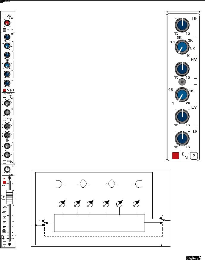
EQ
Many audio signals coming into the console require some degree of corrective eq in order to be part of a good sounding mix. XR-20 & XR-24 offer a very useful and great sounding eq section on each channel.The input EQ consists of four bands: High, High-mid, Low-mid and Low. The High and Low frequency bands each have a boost/cut control and their frequencies are fixed.The High-mid and Lowmid bands each have variable boost/cut and variable frequency.
high frequency—HF
Boost / Cut 15dB boost and cut. Shelving @ 12 kHz
high mid—HM
Frequency Continuously sweepable between 400 Hz and 8 kHz.
Boost / Cut 15dB boost and cut. Bell curve with a Q of 1
Low mid—LM
Frequency Continuously sweepable between 100 Hz and 2 kHz.

 Boost / Cut 15dB boost and cut. Bell curve with a Q of 1
Low frequency—LF
Boost / Cut 15dB boost and cut. Shelving @ 80 Hz.
EQ on
 Equalizer is on. This switch is used to activate the EQ section and can be used to make A/B comparisons between "flat" and eq'd signals.
p. 9
1 Mono input channel
XR-20 / XR-24 owner’s manual
Module
Block diagram |
|
|
|
|
|
|
||
EQ ON |
|
|
PAN |
MONO |
L-R |
G1-2 |
G3-4 |
|
CHAN |
|
|
|
|
|
|
||
|
|
|
|
|
|
|
|
|
HF |
|
FADER |
FADER AMP |
|
|
|
|
|
12 KHZ |
|
|
|
|
|
|
|
|
|
|
|
|
|
|
|
|
|
|
|
|
+10 |
|
BUS ASSIGN |
|
||
|
|
|
|
|
SWITCHES |
|
||
|
|
|
|
|
|
|
||
|
|
100MM |
|
|
|
|
|
|
|
|
|
YES |
|
PAN |
|
LEVEL |
|
|
|
|
PRE |
A1-2 |
1-2 |
|
1-2 |
|
|
|
|
SOURCE |
PRE |
|
|
|
A1 |
|
|
|
MUTE ? |
|
|
|
|
|
|
|
|
NO |
|
|
|
|
A2 |
PRE |
|
|
|
|
|
|
|
|
|
|
|
|
|
|
|
|
|
EQ |
|
PRE |
|
|
|
|
|
|
|
|
FADER |
|
A3-4 |
|
|
LEV 3 |
A3 |
|
|
|
|
PRE |
|
|
|
|
|
|
|
PRE-SOURCE |
|
|
|
|
|
|
|
|
BUFFER |
|
|
|
LEV 4 |
|
|
|
|
|
|
|
|
A4 |
|
|
|
|
|
|
|
|
|
|
PRE |
|
|
|
A5-6 |
|
|
LEV 5 |
|
INSERT |
PRE-SOURCE |
|
|
|
A5 |
|||
|
PRE |
|
|
|
||||
|
SELECT |
|
|
|
|
|||
|
|
|
|
|
|
|
||
|
|
|
|
|
|
|
LEV 6 |
A6 |
|
|
|
|
|
|
|
|
|
AUX SENDS 1 THRU 6
Controls |
p. 10

Mono Input channel 1
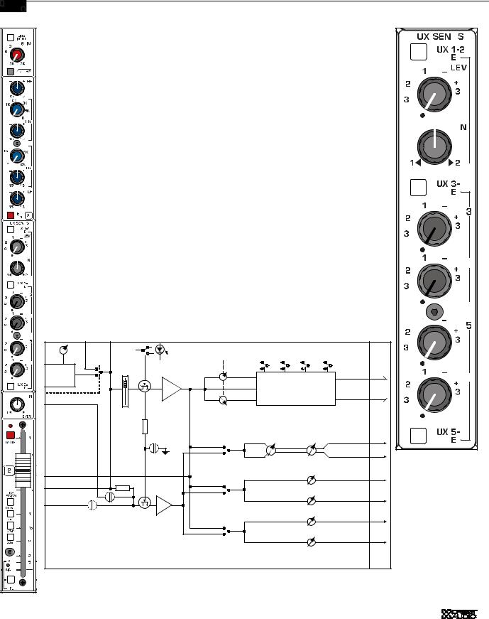
AUX send features
Six auxiliary sends are available for creating individual output mixes. These can be used to drive effects processors, provide monitor mixes, create broadcast or alternate sound reinforcement mixes, or for other special requirements.
Note:The default PRE setting for the Auxes is pre-fader, but post-mute, post-insert, and post eq. Internal settings can be changed so that PRE is also preeq and pre mute
Aux 1 - 2 PRE
 AUX 1/2 stereo pair is post fader
AUX 1/2 stereo pair is pre-fader
Aux sends 1 & 2
Auxes 1 and 2 are configured as a stereo pair. The top knob controls the level and the bottom knob acts as a PAN control.This stereo aux send can be used for any type of stereo feed from the console, such as live two-track recording, stereo in-ear monitors, alternate stereo feed for broadcast, and stereo signal processors. Also, by properly using the pan control Auxes 1 and 2 can be used as discrete mono Aux buses

 Aux 1/2 level Send level for the Aux 1/2 stereo pair
Aux 1/2 PAN Stereo placement for the Aux 1/2 stereo pair
AUX 3-4 PRE
 AUX 3 and AUX 4 are post fader
AUX 3 and AUX 4 are pre-fader
Aux sends 3, 4, 5 & 6
Auxes 3, 4, 5, & 6 are configured as descrete mono aux sends. They are typically used to feed signal processors and for on-stage monitors.
Auxes 3, 4, 5, &6 level Set levels Auxes 3, 4, 5, & 6.
AUX 5-6 PRE
 AUX 5 and AUX 6 are post fader.
AUX 5 and AUX 6 are pre-fader.
p. 11
1 Mono input channel
XR-20 / XR-24 owner’s manual
|
Module |
|
|
|
|
|
|
Controls |
|||||||||||||
|
|
|
|
|
|
|
|
|
|
|
|
|
|
|
|
|
|
|
|
|
|
|
|
|
|
|
|
|
|
|
|
|
|
|
|
|
|
|
|
|
|
|
|
|
|
|
|
|
|
|
|
|
|
|
|
|
|
|
|
|
|
|
|
|
|
|
|
|
|
|
|
|
|
|
|
|
|
|
|
|
|
|
|
|
|
|
|
|
|
|
|
|
|
|
|
|
|
|
|
|
|
|
|
|
|
|
|
|
|
|
|
|
|
|
|
|
|
|
|
|
|
|
|
|
|
|
|
|
|
|
|
|
|
|
|
|
|
|
|
|
|
|
|
|
|
|
|
|
|
|
|
|
|
|
|
|
|
|
|
|
|
|
|
|
|
|
|
|
|
|
|
|
|
|
|
|
|
|
|
|
|
|
|
|
|
|
|
|
|
|
|
|
|
|
|
|
|
|
|
|
|
|
|
|
|
|
|
|
|
|
|
|
|
|
|
|
|
|
|
|
|
|
|
|
|
|
|
|
|
|
|
|
|
|
|
|
|
|
|
|
|
|
|
|
|
|
|
|
|
|
|
|
|
|
|
|
|
|
|
|
|
|
|
|
|
|
|
|
|
|
|
|
|
|
|
|
|
|
|
|
|
|
|
|
|
|
|
|
|
|
|
|
|
|
|
|
|
|
|
|
|
|
|
|
|
|
|
|
|
|
|
|
|
|
|
|
|
|
|
|
|
|
|
|
|
|
|
|
|
|
|
|
|
|
|
|
|
|
|
|
|
|
|
|
|
|
|
|
|
|
|
|
|
|
|
|
|
|
|
|
|
|
|
|
|
|
|
|
|
|
|
|
|
|
|
|
|
|
|
|
|
|
|
|
|
|
|
|
|
|
|
|
|
|
|
|
|
|
|
|
|
|
|
|
|
|
|
|
|
|
|
|
|
|
|
|
|
|
|
|
|
|
|
|
|
|
|
|
|
|
|
|
|
|
|
|
|
|
|
|
|
|
|
|
|
|
|
|
|
|
|
|
|
|
|
|
|
|
|
|
|
|
|
|
|
|
|
|
|
|
|
|
|
|
|
|
|
|
|
|
|
|
|
Block diagram
PFL
SOLO LEFT
SOLO RIGHT
TO |
|
PEAK |
|
CIRCUIT |
SOLO DC |
|
MUTE
EQ ON |
|
PAN |
MONO |
L-R |
G1-2 |
G3-4 |
CHAN |
|
|
|
|
|
|
|
|
|
|
|
|
|
|
FADER |
FADER AMP |
|
|
|
|
|
|
|
|
|
|
+10 |
BUS ASSIGN |
|
SWITCHES |
||
|
100MM
|
YES |
|
PAN |
LEVEL |
|
PRE |
A1-2 |
1-2 |
1-2 |
|
SOURCE |
PRE |
|
A1 |
|
MUTE ? |
|
|
|
A2 |
RE |
|
NO |
|
|
|
|
|
|
EQ |
PRE |
|
|
|
|
|
|
|
|
FADER |
|
A3-4 |
|
LEV 3 |
|
||
|
|
|
PRE |
|
|
A3 |
|
|
|
|
|
|
|||||
PRE-SOURCE |
|
BUFFER |
LEV 4 |
|
|
|
A4 |
PRE-SOURCE |
A5-6 |
LEV 5 |
||||
PRE |
A5 |
|||||
SELECT |
||||||
|
|
|
|
|
LEV 6 |
|
|
|
|
|
|
||
|
|
|
|
|
A6 |
|
AUX SENDS 1 THRU 6
p. 12

Mono Input channel 1
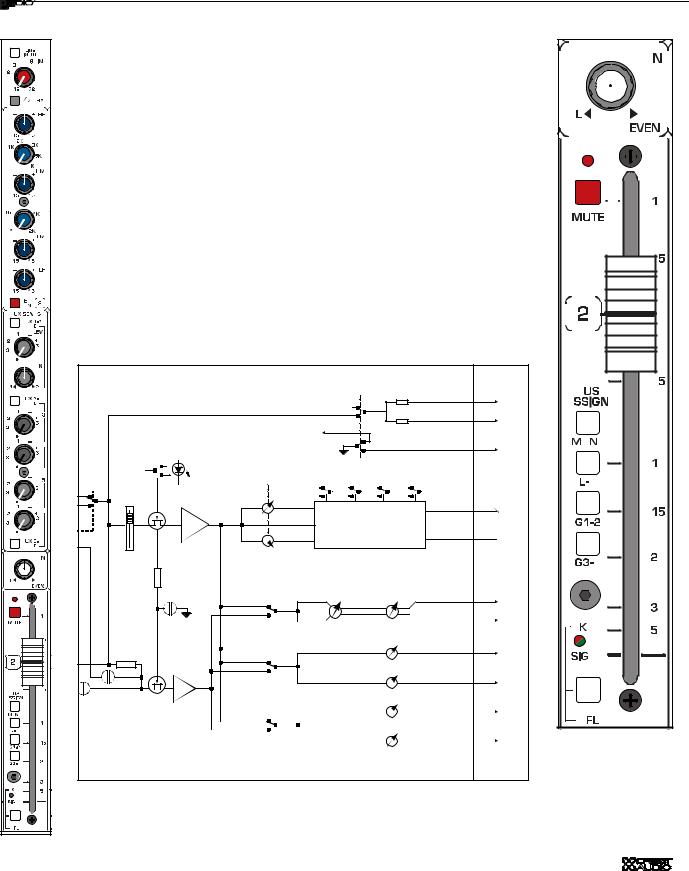
Bus assignment features
The bus assignment section offers considerable flexibility for creating what eventually becomes the main output mix.Two stereo subgroups are available for creating submixes or separate stereo mixes. All assignments are derived post-fader, post-eq, and post-mute.
PAN control

 The pan control positions the signal within the stereo left/right (or odd/even) field. PAN affects signals that are assigned directly to Left-Right, Groups 1-2 and Groups 3-4
Mono bus assign
The channel is assigned to the MONO mix bus. PAN has no affect on
MONO
L-R bus assign
 The channel is assigned to the Left and Right mix buses.
G 1-2 bus assign
 The channel is assigned to Groups 1 and 2. Groups 1 and 2 are configured as a stereo pair.They can also be treated as two discrete mono groups by using the PAN control.
G 3-4 bus assign
 The channel is assigned Groups 3 and 4. Groups 4 and 4 are configured as a stereo pair.They can also be treated as two discrete mono groups by using the PAN control.
Input fader (100mm)
The fader is the primary level control for signals being sent to any of the consoles post fader mix buses,
MUTE
 The input channel is muted and the MUTE LED is alluminated. All AUX feeds and bus assignments are shut off. Insert send and SOLO signals are still active.
PK / SIG LED indicator
 This two-color(green & red) LED is used to monitor the channel’s signal level. Signal present (green) is monitored pre-fader. Peak (red) is monitored at the preamp and before & after the fader.
PFL
 PFL -Pre fader listen.This button routes the channel’s signal to the Solo bus for monitoring through headphones or in the control room.The Peak (red) LED is illuminated to show PFL status.
p. 13
 Loading...