


PROFESSIONAL POWER AMPLIFIERS
|
|
|
C ip/Limit |
|
7301 Professional Power Amp if er |
|
|
|
Signal |
|
|
|
|
|
Temp/DC |
|
|
|
|
-6 |
Ac ive |
|
6 |
- |
0 |
|
|
||
-3 |
- |
0 |
3 |
||
- 5 |
|
|
- 5 |
|
|
-30 |
- |
-30 |
- |
||
|
|
||||
|
80 |
0dB |
-80 |
0dB |
|
|
|
LOWS |
|
H GHS |
|
|
|
|
Clip/Limit |
|
7001 Professional Power Amp if er |
|
|
|
|
|
|
|
|
|
Signal |
|
|
|
|
|
Temp/DC |
|
|
|
|
6 |
Active |
|
6 |
- |
0 |
|
|
||
-3 |
- |
0 |
-3 |
||
- 5 |
|
|
- 5 |
|
|
-30 |
|
- |
-30 |
|
- |
|
|
|
|
||
-80 |
0dB |
-80 |
0dB |
||
|
|
Ch A |
|
|
Ch B |
|
|
|
Clip/Limit |
|
6001 Professional Power Amp if er |
|
|
|
Signal |
|
|
|
|
|
Temp/DC |
|
|
|
|
6 |
Active |
|
6 |
- |
0 |
|
|
||
-3 |
- |
0 |
-3 |
||
- 5 |
|
|
- 5 |
|
|
-30 |
|
- |
-30 |
|
- |
|
|
|
|
||
-80 |
0dB |
-80 |
0dB |
||
|
|
Ch A |
|
|
Ch B |
|
|
|
Clip/Lim t |
|
4801 Professional Power Amp if er |
|
|
|
|
|
|
|
|
|
S gnal |
|
|
|
|
|
Temp DC |
|
|
|
|
6 |
Active |
|
-6 |
- |
0 |
|
|
||
-3 |
- |
0 |
-3 |
||
- 5 |
|
|
- 5 |
|
|
-30 |
|
- |
-30 |
|
- |
|
|
|
|
||
-80 |
0dB |
-80 |
0dB |
||
|
|
Ch A |
|
|
Ch B |
|
|
|
Clip/Lim t |
|
4601 Profess onal Power Amp i ier |
|
|
|
|
|
|
|
|
|
S gnal |
|
|
|
|
|
Temp DC |
|
|
|
|
6 |
Active |
|
-6 |
- |
0 |
|
|
||
3 |
- |
0 |
3 |
||
- 5 |
|
|
- 5 |
|
|
-30 |
|
- |
30 |
|
- |
|
|
|
|
||
-80 |
0dB |
-80 |
0dB |
||
|
|
Ch A |
|
|
Ch B |
|
|
|
Clip Lim t |
|
3301 P ofess onal Power Ampli ier |
|
|
|
|
|
|
|
|
|
S gnal |
|
|
|
|
|
Temp DC |
|
|
|
|
6 |
Active |
|
-6 |
- |
0 |
|
|
||
-3 |
- |
0 |
3 |
||
- 5 |
|
|
- 5 |
|
|
-30 |
|
- |
30 |
|
- |
|
|
|
|
||
-80 |
0dB |
80 |
0dB |
||
|
|
Ch A |
|
|
Ch B |
|
|
|
C ip/Limit |
|
MA7120 Pro essional Power Ampl fier |
|
|
|
|
|
|
|
|
|
Signal |
|
|
|
|
|
Temp/DC |
|
|
|
|
-6 |
Ac ive |
|
-6 |
- |
0 |
3 |
- |
0 |
3 |
- 5 |
|
|
- 5 |
|
|
30 |
|
- |
-30 |
|
- |
|
|
|
|
||
80 |
0dB |
-80 |
0dB |
||
|
|
Ch A |
|
|
Ch B |
|
|
|
C ip Limit |
|
MA5850 Pro ess onal Power Ampl fier |
|
|
|
Signal |
|
|
|
|
|
Temp/DC |
|
|
|
|
-6 |
Active |
|
-6 |
- |
0 |
|
|
||
3 |
- |
0 |
3 |
||
- 5 |
|
|
- 5 |
|
|
30 |
|
- |
-30 |
|
- |
|
|
|
|
||
80 |
0dB |
80 |
0dB |
||
|
|
Ch A |
|
|
Ch B |
10004 Professional Power Ampl fier
|
|
Cl p |
im t |
|
|
|
Cl p |
mit |
|
|
|
Signal |
|
|
|
S gnal |
|
||
|
|
emp DC |
|
|
|
emp DC |
|
||
|
|
Ac ive |
|
|
|
Act ve |
|
||
|
-6 |
|
|
|
-6 |
- 0 |
-6 |
- 0 |
-6 |
- 0 |
|
3 |
- 0 |
|
-3 |
3 |
3 |
||
- 5 |
|
|
- 5 |
|
|
- 5 |
|
- 5 |
- |
30 |
|
- |
30 |
|
|
-30 |
- |
-30 |
|
|
|
|
|
|
|
||||
-80 |
|
0dB |
80 |
0dB |
-80 |
0dB |
-80 |
0dB |
|
Ch A |
|
Ch B |
|
Ch C |
|
Ch D |
|||
|
|
|
|
|
|
10001 Professional Power Ampl fier |
|||
|
|
C ip |
mit |
|
|
|
C ip |
im t |
|
|
|
Signal |
|
|
|
Signal |
|
||
|
|
emp DC |
|
|
|
emp DC |
|
||
|
|
Ac ive |
|
|
|
Active |
|
||
|
-6 |
|
|
|
|
|
|
- 0 |
-6 |
- 0 |
|
3 |
|
|
|
|
|
3 |
|
- 5 |
|
|
|
|
|
|
|
- 5 |
|
30 |
|
- |
|
|
|
|
|
-30 |
- |
|
|
|
|
|
|
|
|
||
-80 |
|
0dB |
|
|
|
|
|
-80 |
0dB |
Ch A |
|
|
|
|
|
|
Ch B |
||
|
|
|
|
|
|
9001 Profess onal Power Ampl fier |
|||
|
|
|
C ip |
im t |
|
|
|
|
|
|
|
|
S gnal |
|
|
|
|
|
|
|
|
|
emp DC |
|
|
|
|
||
|
|
|
Act ve |
|
|
|
|
|
|
|
|
-6 |
|
|
6 |
|
|
|
|
- |
0 |
|
3 |
- |
0 |
-3 |
|
|
|
- 5 |
|
|
|
- 5 |
|
|
|
|
|
30 |
|
- |
-30 |
|
- |
|
|
|
|
|
|
|
|
|
|
|
|||
|
80 |
0dB |
-80 |
0dB |
|
|
|
||
|
|
Ch A |
|
|
Ch B |
|
|
|
|
|
|
|
|
|
|
8001 Profess onal Power Ampl fier |
|||
|
|
|
C ip |
im t |
|
|
|
|
|
|
|
|
S gnal |
|
|
|
|
|
|
|
|
|
emp DC |
|
|
|
|
||
|
|
|
Act ve |
|
|
|
|
|
|
|
|
-6 |
|
|
6 |
|
|
|
|
- |
0 |
|
3 |
- |
0 |
-3 |
|
|
|
- 5 |
|
|
|
- 5 |
|
|
|
|
|
30 |
|
- |
-30 |
|
- |
|
|
|
|
|
|
|
|
|
|
|
|||
|
80 |
0dB |
-80 |
0dB |
|
|
|
||
|
|
Ch A |
|
|
Ch B |
|
|
|
|
|
|
|
|
|
|
MA9130 Professional Power Ampl fier |
|||
|
|
|
C ip |
m t |
|
|
|
|
|
|
|
|
S gnal |
|
|
|
|
|
|
|
|
|
emp DC |
|
|
|
|
||
|
|
|
Act ve |
|
|
|
|
|
|
|
|
-6 |
|
|
-6 |
|
|
|
|
- |
0 |
|
3 |
- |
0 |
3 |
|
|
|
- 5 |
|
|
|
- 5 |
|
|
|
|
|
--
-30 |
|
30 |
|
-80 |
0dB |
80 |
0dB |
|
Ch A |
|
Ch B |
OWNER’S MANUAL
Including MA Series Amplifiers

Important Precautions
This symbol is used to alert the operator to follow important operating procedures and precautions detailed in documentation.
This symbol is used to warn operators that uninsulated “dangerous voltages” are present within the equipment enclosure that may pose a risk of electric shock.
1.Save the carton and packing material even if the equipment has arrived in good condition. Should you ever need to ship the unit, use only the original factory packing.
2.Read all documentation before operating your equipment. Retain all documentation for future reference.
3.Follow all instructions printed on unit chassis for proper operation.
4.Do not spill water or other liquids into or on the unit, or operate the unit while standing in liquid.
5.Make sure power outlets conform to the power requirements listed on the back of the unit.
6.Do not use the unit if the electrical power cord is frayed or broken. The power supply cords should be routed so that they are not likely to be walked on or pinched by items placed upon or against them, paying particular attention to cords and plugs, convenience receptacles, and the point where they exit from the appliance.
7.Always operate the unit with the AC ground wire connected to the electrical system ground. Precautions should be taken so that the means of grounding of a piece of equipment is not defeated.
8.Mains voltage must be correct and the same as that printed on the rear of the unit. Damage caused by connection to improper AC voltage is not covered by any warranty.
9.Have gain controls on amplifiers turned down during power-up to prevent speaker damage if there are high signal levels at the inputs.
10.Power down & disconnect units from mains voltage before making connections.
11.Never hold a power switch in the “ON” position if it won’t stay there itself!
12.Do not use the unit near stoves, heat registers, radiators, or other heat producing devices.
13.Do not block fan intake or exhaust ports. Do not operate equipment on a surface or in an environment which may impede the normal flow of air around the unit, such as a bed, rug, weathersheet, carpet, or completely enclosed rack. If the unit is used in an extremely dusty or smoky environment, the unit should be periodically “blown free” of foreign matter.
14.Do not remove the cover. Removing the cover will expose you to potentially dangerous voltages. There are no user serviceable parts inside.
15.Connecting amplifier outputs to oscilloscopes or other test equipment while the amplifier is in bridged mode may damage both the amplifier and test equipment!
16.Do not drive the inputs with a signal level greater than that required to drive equipment to full output.
17.Do not connect the inputs / outputs of amplifiers or consoles to any other voltage source, such as a battery, mains source, or power supply, regardless of whether the amplifier or console is turned on or off.
18.Do not run the output of any amplifier channel back into another channel’s input. Do not parallelor seriesconnect an amplifier output with any other amplifier output. Crest Audio is not responsible for damage to loudspeakers for any reason.
19.Do not ground any + (“hot”) terminal. Never connect a + (“hot”) output to ground or to another + (“hot”) output!
20.Non-use periods. The power cord of equipment should be unplugged from the outlet when left unused for a long period of time.
21. Service Information E q u i p m e n t should be serviced by qualified service personnel when:
A.The power supply cord or the plug has been damaged;
B.Objects have fallen, or liquid has been spilled into the equipment;
C.The equipment has been exposed to rain;
D. The equipment does not appear to operate normally, or exhibits a marked change in performance;
E.The equipment has been dropped, or the enclosure damaged.
22.To obtain service, contact your nearest Crest Audio Service Center, Distributor, Dealer, or Crest Audio at 201.909.8700 (USA).
All Professional Series power amplifier models are UL LISTED, except for:
10001
10004
MA5850
MA7120
MA9130

Power Amplifier Owner’s Manual
Table of Contents
Introduction . . . . . . . . . . . . . . . . . . . . . . . . . . . . . . . . . 2
Unpacking . . . . . . . . . . . . . . . . . . . . . . . . . . . . . . . . . . 2
Mounting . . . . . . . . . . . . . . . . . . . . . . . . . . . . . . . . . . . 2
Cooling Requirements . . . . . . . . . . . . . . . . . . . . . . . . . 3
Operating Precautions. . . . . . . . . . . . . . . . . . . . . . . . . . 3
Crest Audio Model 7301 Power Amplifier . . . . . . . . . . 3
Crest Audio Model 10004 Power Amplifier . . . . . . . . . 3
Models 3301, 4801, 6001 Features . . . . . . . . . . . . . . . . 4
Model 4601 Features . . . . . . . . . . . . . . . . . . . . . . . . . . 4
Model 7001 Features . . . . . . . . . . . . . . . . . . . . . . . . . . 5
Model 7301 Features . . . . . . . . . . . . . . . . . . . . . . . . . . 5
Model 8001 Features . . . . . . . . . . . . . . . . . . . . . . . . . . 6
Model 9001 Features . . . . . . . . . . . . . . . . . . . . . . . . . . 7
Model 10001 Features . . . . . . . . . . . . . . . . . . . . . . . . . 8
Model 10004 Features . . . . . . . . . . . . . . . . . . . . . . . . . 9
Connecting Inputs. . . . . . . . . . . . . . . . . . . . . . . . . . . . 10
Connecting Outputs . . . . . . . . . . . . . . . . . . . . . . . . . . 10
Crest Audio Octal Sockets . . . . . . . . . . . . . . . . . . . . . 10
NexSys® . . . . . . . . . . . . . . . . . . . . . . . . . . . . . . . . . . . 10
Connecting Power. . . . . . . . . . . . . . . . . . . . . . . . . . . . 11
Operation Modes . . . . . . . . . . . . . . . . . . . . . . . . . . . . 11
Bridging Precautions . . . . . . . . . . . . . . . . . . . . . . . . . 12
Switches and Controls . . . . . . . . . . . . . . . . . . . . . . . . 12
Indicators . . . . . . . . . . . . . . . . . . . . . . . . . . . . . . . . . . 13
Protection Features . . . . . . . . . . . . . . . . . . . . . . . . . . . 13
Speaker Protection . . . . . . . . . . . . . . . . . . . . . . . . . . . 15
Amplifier Maintenance and User Responsibility . . . . . 15
Service/Warranty Information . . . . . . . . . . . . . . . . . . . 15
Professional Series Block Diagram . . . . . . . Appendix A
General Amplifier Specifications . . . . . . . . . Appendix B
Wire Gauge Charts. . . . . . . . . . . . . . . . . . . . Appendix C
Meyer-Compatible Power Amplifiers . . . . . . Appendix D
Crest Audio Pro Series Power Amplifiers |
Page 1 |

Introduction
Congratulations...on your purchase of a Crest Audio Professional Series power amplifier. Designed for years of reliable, flawless operation under rigorous use. These power amplifiers offer the sonic superiority and unsurpassed reliability for which Crest Audio is famous, while remaining surprisingly compact. Advanced technology and extensive protection circuitry allow operation with greater efficiency into difficult loads and power conditions. All Professional Series amplifiers are fully compatible with Crest Audio’s Octal Socket Accessories and the NexSys computer-controlled audio system. The IGM (Instantaneous Gain Modulation) circuit ensures trou- ble-free operation into loads as low as 2Ω. The clip limiting circuits protect drivers and ensure that sonic integrity is maintained, even in extreme overload conditions. Crest Audio’s high-efficiency design uses tunnel-cooled heatsinks and variable speed DC fans. This cooling topology maintains a lower overall operating temperature, resulting in longer output transistor life.
Model 9001, 10001, and 10004 power amplifiers use Crest Audio’s innovative “Power Density” circuitry.
Although the Crest Audio Professional Series amplifiers are quite simple to operate, and are housed in ultra-strong steel chassis, improper use can be dangerous. Some of these models are very high-powered amplifiers that can put out high voltages and sizable currents at frequencies up to 30 kHz. Always use safe operating techniques with these amplifiers. FOR YOUR SAFETY, READ THE
IMPORTANT PRECAUTIONS SECTION , AS WELL AS INPUT, OUTPUT, AND POWER CONNECTION SECTIONS.
Unpacking
Upon unpacking, inspect the amplifier. If you find any damage, notify your supplier immediately. Only the consignee may institute a claim with the carrier for damage incurred during shipping. Be sure to save the carton and all packing materials. Should you ever need to ship the unit back to Crest Audio, one of its offices, service centers, or the supplier, use only the original factory packing. If the shipping carton is unavailable, contact Crest to obtain a replacement.
Mounting
Professional Series power amplifiers will mount in standard 19-inch racks having sufficient depth. The 10004 & 10001 amplifiers are four rack units high; the 9001 and 8001 models are three rack-spaces high, while the remainder are two rack-space units. All two and three-rack space units (except for the 9001) are provided with four front panel mounting holes. The 9001, 10001, and 10004 have eight front panel mounting holes. Crest Audio recommends using all mounting holes to secure the power amplifier in the rack; this will ensure the safety of the equipment. Rear mounting ears are also provided on all amplifiers for additional support, which is essential in non-permanent installations like mobile or touring sound systems, but recommended for permanent installations as well. Because of the cables and connectors on the rear panel, a right-angle or offset screwdriver or hex key will make it easier to fasten the rear mounting ears to the rails.
Note: The 10001 and 10004 models, because of their size, require rack mounting screws stronger than standard rack screws. For customers in the USA, these are supplied with the unit. Customers in Europe and Asia should mount these models using heavy-duty metric bolts.
Page 2 |
Crest Audio Pro Series Power Amplifiers |

Cooling Requirements
The Professional Series amplifiers use a forced-air cooling system to maintain a low, even operating temperature. Air is drawn into the amplifier by fan(s) on the rear panel, courses through the cooling fins of the back-to-back (tunnel-configured) channel heat sinks, and then exhausts through the front panel slots.
If either heat sink gets too hot, its sensing circuit will open the output relay, disconnecting the load from that particular channel. If the power transformer overheats, another sensing circuit opens the output relays on all channels until it cools to a safe temperature.
It is important to have an adequate air supply at the back of the amplifier and enough space around the front of the amplifier to allow the cooling air to escape. If the amp is rack mounted, do not use doors or covers on the front of the rack; the exhaust air must flow without resistance. If you are using racks with closed backs, use fans on the rear rack panel to pressurize the rack and ensure an ample air supply; also make sure that there is one (1) standard rack space opening for every three mounted power amplifiers.
The Professional Series amplifiers are supplied with cooling fan air filters. The filters snap in place over the fan housing. Any filter will decrease airflow somewhat, so use the filter only when the amplifier is used in a dusty environment without a filtered air supply. The filter element must be cleaned or replaced periodically (see the section on Amplifier Maintenance for filter service procedures).
Operating Precautions
Make sure the mains voltage is correct and is the same as that printed on the rear of the amplifier. Damage caused by connecting the amplifier to improper AC voltage is not covered by any warranty. See the Connecting Power section for more information on voltage requirements.
Note: Always turn off and disconnect the amplifier from mains voltage before making audio connections. Also, as an extra precaution, have the attenuators turned down during power-up.
Although the Professional Series amplifiers have AutoRamp circuitry, which raises the signal level gradually after the output relay closes, it is always a good idea to have the gain controls turned down during power-up to prevent speaker damage if there is a high signal level at the inputs. Whether you buy or make them, use good-quality connections, input cables, and speaker cables, along with good soldering technique, to ensure trouble-free operation. Most intermittent problems are caused by faulty cables.
Consult the Wire Gauge Charts to determine proper gauges for different load impedances and cable lengths. Remember that cable resistance robs amplifier power in two ways: power lost directly to resistance (I2R loss), and by lowering the total load impedance. Also make sure the mode switch is correctly set for the desired application. See Sections on Stereo, Parallel, and Bridged Mono Operation for more information.
The Crest Audio Model 7301 Power Amplifier
The Model 7301 is specifically designed for use in bi-amplified systems; because of its dissimilar channel design, the specifications are reported in a separate fashion. The 7301 power specifications were obtained by driving the low frequency channel with a 100 Hz signal and the high frequency channel with a 1 kHz signal.
The Crest Audio Model 10004 Power Amplifier
The Model 10004 power amplifier is unique in that it is a high-power, four-channel amplifier. Offering the advantages of Crest Audio’s Power Density engineering design philosophy, this amplifier provides 1400 watts at 2Ω from each of the four channels. All four channels have independent LED indicators, attenuation, and input /output connections. Power switching and NexSys interfaces are configured in pairs of two. Because a channel may have to drive more than one speaker line, each channel has two pairs of output binding posts. The red binding posts are hot (+), while the black binding posts are at signal ground (-).
Crest Audio Pro Series Power Amplifiers |
Page 3 |

|
|
|
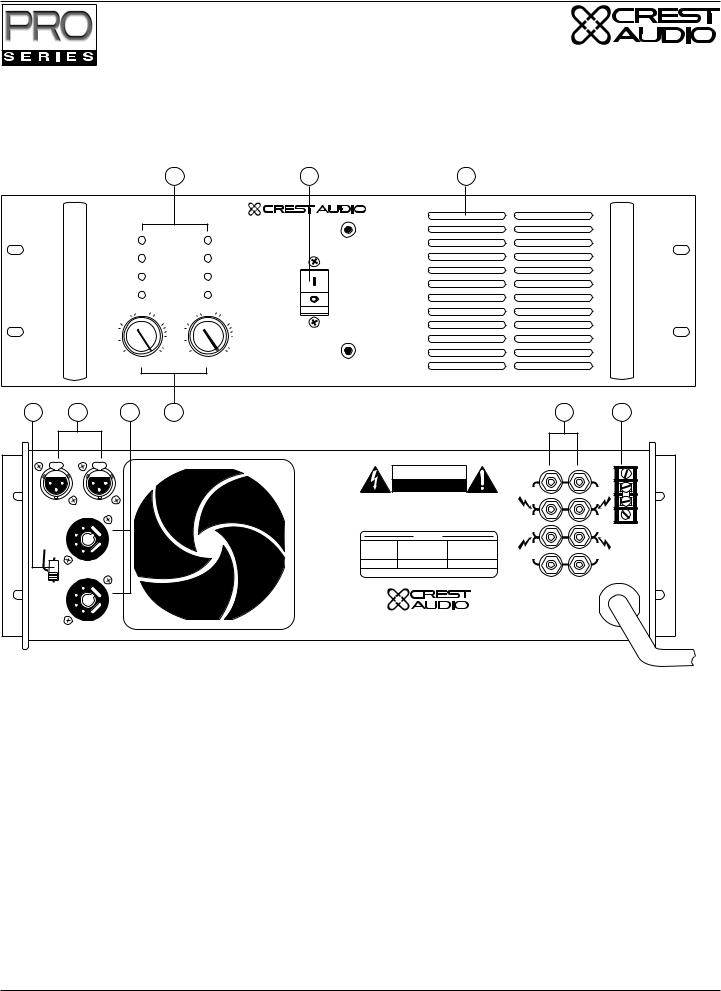
Models 3301, 4801, 6001 Features |
|
|
1 |
|
2 |
3 |
|
|
|
|
|
|
Clip/Limit |
3301 Professional Power Amplifier |
|
|
|
|
|
||
|
Signal |
|
|
|
|
Temp/DC |
|
|
|
|
Active |
|
-6 |
|
-10 |
-6 |
|
|
|
-3 |
-10 |
-3 |
|
|
-15 |
-1 |
-15 |
|
|
-30 |
-30 |
-1 |
|
|
|
|
|
||
-80 |
0dB |
-80 |
0dB |
|
|
Ch A |
|
Ch B |
|
4 |
5 |
6 |
7 |
8 |
|
|
|
|
9 |
|
|
|
|
|
|
|
CAUTION |
|
|
|
|
S EREO |
PARALLEL |
|
|
RISK OF ELEC RIC SHOCK |
|||
|
|
|
|
|
DO NO |
OPEN |
|
||
|
|
BRIDGE |
|
|
|
|
|||
|
|
|
AV S : RISQUE DE CHOC ÉLEC RIQUE |
NE PAS OUVRIR |
|||||
|
|
|
|
|
|||||
|
|
|
|
A |
WARNING |
O REDUCE HE RISK O |
IRE OR E EC RIC SHOCK DO NO |
||
|
|
|
|
|
EX OSE |
H S EQUI MEN |
O RAIN OR MOIS URE |
||
|
|
PIN 3+ |
|
|
A EN |
ON! OUR ÉVI ER E RISQUE D NCENDIE OU DE CHOC |
|||
|
|
|
|
|
É EC RIQUE NE |
ACEZ AS CE |
A AREI |
SOUS A UIE OU Á |
|
|
|
N A |
|
|
|
|
HUM DI É |
|
|
|
|
|
|
|
|
|
|
|
|
|
|
PUSH |
|
|
|
|
|
|
|
|
|
|
|
|
|
|
|
|
SIGNAL |
|
|
|
|
|
|
|
|
|
GROUND |
|
|
|
|
|
|
|
|
|
LIFT |
|
|
N B |
|
B |
|
|
USA ONLY |
|
|
|
|
PUSH |
|
|
|
MAXIMUM |
OUTPUT POWER |
||
|
|
|
|
MODEL # |
INPUT CURRENT |
IN WATTS PER |
|||
|
|
|
|
|
|
|
@ 120V, 60Hz |
CHANNEL, Ω |
|
|
|
|
|
|
3301 |
11 AMPS |
330W |
||
|
|
|
|
|
|
OUTPUT - CLASS 2 WIR NG MAY BE USED |
|||
10
OUT A
+
BRIDGE
OUT B
Des gned & manufactured in the USA by:
Crest Audio Inc.
100 Eisenhower Dr.
Paramus, New Jersey 07652 USA
1-Channel A & B Clip/Limit, Signal, Temp/DC, and Active LEDs. 2-Combination Circuit Breaker/Power Switch. 3-Heated Air Exhaust Grill. 4-Fan Intake Grill & Filter 5-Channel A & B Gain Attenuators. 6-Channel A & B XLR Input Connectors. 7-Mode Select Switch.
8-Crest Audio Octal Accessory Sockets. 9-Signal Ground Lift Barrier Strip. 10-Five-Way Output Binding Post Connectors.
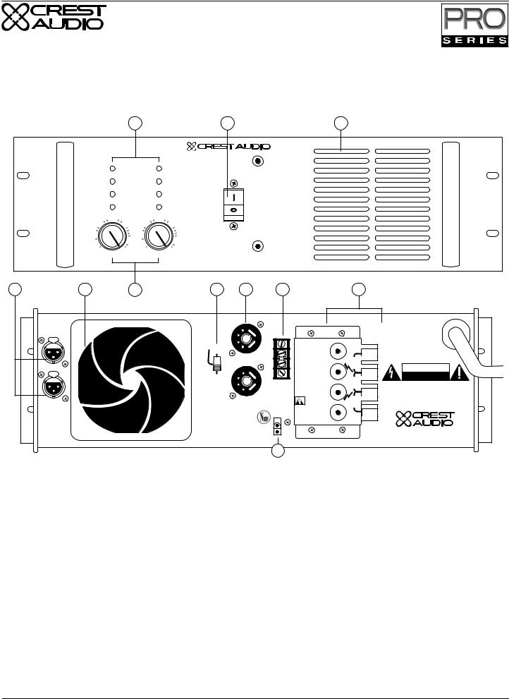
Model 4601 & 7001 Features
|
|
1 |
|
2 |
|
|
|
|
|
3 |
|
|
|
|
|
|
|
|
|
|
|
|
|
Clip/Limit |
|
|
4601 Professional Power Amplifier |
|
||||
|
|
|
|
|
|
|
|
|
||
|
|
Signal |
|
|
|
|
|
|
|
|
|
|
Temp/DC |
|
|
|
|
|
|
|
|
|
|
Active |
|
-6 |
|
|
|
|
|
|
|
-10 |
-6 |
|
|
|
|
|
|
|
|
|
-3 |
-10 |
-3 |
|
|
|
|
|
|
|
|
-15 |
-1 |
-15 |
|
|
|
|
|
|
|
|
-30 |
-30 |
-1 |
|
|
|
|
|
|
|
|
|
|
|
|
|
|
|
|
||
|
-80 |
0dB |
-80 |
0dB |
|
|
|
|
|
|
|
|
Ch A |
|
Ch B |
|
|
|
|
|
|
4 |
5 |
6 |
|
7 |
8 |
|
|
|
9 |
10 |
S EREO PARALLEL |
|
|
|
|
|
CAUTION |
|
OUT A |
||
|
|
|
|
|
RISK OF ELECTRIC SHOCK |
|
||||
BRID |
E |
|
|
|
|
|
|
|||
|
|
|
|
|
DO NOT OPEN |
|
|
|
||
|
|
|
|
|
|
|
|
|
|
|
|
|
|
|
|
A |
AVIS : RISQUE DE CHOC ÉLEC RIQUE |
NE PAS OUVRIR |
+ |
||
|
|
|
|
|
WARN NG TO REDUCE THE RISK OF F RE OR ELECTR C SHOCK DO NOT |
BRIDGE |
||||
PIN 3+ |
|
|
|
|
|
EXPOSE THIS EQUIPMENT TO RA N OR MO STURE. |
|
|||
IN A |
|
|
|
|
|
ATTENT ON! POUR ÉVITER LE RISQUE D INCEND E OU DE CHOC |
|
|||
|
|
|
|
|
|
ÉLECTRIQUE, NE PLACEZ PAS CET APPAREIL SOUS LA PLUIE OU Á |
|
|||
PUSH |
|
|
|
|
|
|
L'HUMIDITÉ |
|
|
OUT B |
|
|
|
|
|
|
|
|
|
||
|
|
|
|
|
|
|
|
|
SIGNAL |
|
|
|
|
|
|
|
|
|
|
GROUND |
|
|
|
|
|
|
|
|
USA ONLY |
|
LIFT |
|
IN B |
|
|
|
|
B |
|
|
|
Designed & manufactured in the USA by: |
|
PUSH |
|
|
|
|
|
MAXIMUM |
OUTPUT POWER |
|
||
|
|
|
|
|
MODEL # |
INPUT CURRENT |
|
N WATTS PER |
|
|
|
|
|
|
|
|
|
@ 120V, 60Hz |
|
CHANNEL, Ω |
|
|
|
|
|
|
|
601 |
18 AMPS |
|
25W |
Crest Audio Inc. |
|
|
|
|
|
|
|
|
|
|
|
|
|
|
|
|
|
OUTPUT - CLASS 2 WIRING MAY BE USED |
100 Eisenhower Dr. |
|||
|
|
|
|
|
|
|
|
|
|
Paramus, New Jersey 07652 USA |
1-Channel A & B Clip/Limit, Signal, Temp/DC, and Active LEDs. 2-Combination Circuit Breaker/Power Switch.
3-Heated Air Exhaust Grill. 4-Mode Select Switch. 5-Channel A & B XLR Input Connectors. 6-Channel A & B Gain Attenuators.
7-Fan Intake Grills & Filters. 8-Crest Audio Octal Accessory Sockets
9-Signal Ground Lift Barrier Strip. 10-Five-Way Output Binding Post Connectors.
Page 4 |
Crest Audio Pro Series Power Amplifiers |

|
|
|
Model 7301 Features |
|
|
1 |
|
2 |
3 |
|
|
|
|
|
|
Clip/Limit |
7301 Professional Power Amplifier |
|
|
|
|
|
||
|
Signal |
|
|
|
|
Temp/DC |
|
|
|
|
Active |
|
-6 |
|
-10 |
-6 |
|
|
|
-3 |
-10 |
-3 |
|
|
-15 |
-1 |
-15 |
|
|
-30 |
-30 |
-1 |
|
|
|
|
|
||
-80 |
0dB |
-80 |
0dB |
|
|
LOWS |
HIGHS |
|
|
4 |
5 |
6 |
7 |
LOWS
IN
LOWS
PUSH
PIN 3+
IN
HIGHS
PUSH
HIGHS
|
|
|
CAUTION |
|
|
|
|
||||
|
RISK OF ELEC RIC SHOCK |
|
|
|
|||||||
|
|
|
DO NO |
OPEN |
|
|
|
|
|||
AVIS : R SQUE DE CHOC ÉLEC RIQUE |
NE PAS OUVRIR |
||||||||||
WARNING O REDUCE HE RISK O |
IRE OR E EC RIC SHOCK DO NO |
||||||||||
EX OSE |
HIS EQUI MEN |
O RAIN OR MOIS URE |
|||||||||
A EN ION! OUR ÉVI ER E R SQUE D INCENDIE OU DE CHOC |
|||||||||||
É EC RIQUE NE |
ACEZ AS CE |
A |
AREI |
SOUS A |
U E OU Á |
||||||
|
|
|
HUMIDI É |
|
|
|
|
|
|
|
|
|
|
|
USA ONLY |
|
|
|
|
|
|||
|
|
|
|
|
|
|
|
||||
|
|
|
MAXIMUM |
|
|
|
OUTPUT POWER |
||||
MODEL # |
|
INPUT CURRENT |
|
IN WATTS PER |
|||||||
|
|
|
@ 120V, 60Hz |
|
|
|
CHANNEL, 2Ω |
||||
7301 |
|
|
21 AMPS |
|
|
{ CH. A |
990W |
||||
|
|
|
|
|
|
|
|
CH. B |
220W |
||
OUTPUT - CLASS 2 WIR NG MAY BE USED
8 9
OU LOWS
OU HIGHS
SIGNAL
GROUND
LIF
Des gned & manufactured in the USA by:
Crest Audio Inc.
100 Eisenhower D .
Paramus, New Jersey 07652 USA
1-Lows and Highs Channel Clip/Limit, Signal, Temp/DC, and Active LEDs. 2-Combination Circuit Breaker/Power Switch.
3-Heated Air Exhaust Grill. 4-Lows and Highs Channel XLR Input Connectors. 5-Lows and Highs Channel Attenuators.
6-Fan Intake Grills & Filters. 7-Crest Audio Octal Accessory Sockets.
8-Five-Way Output Binding Post Connectors. 9-Signal Ground Lift Barrier Strip.
Crest Audio Pro Series Power Amplifiers |
Page 5 |
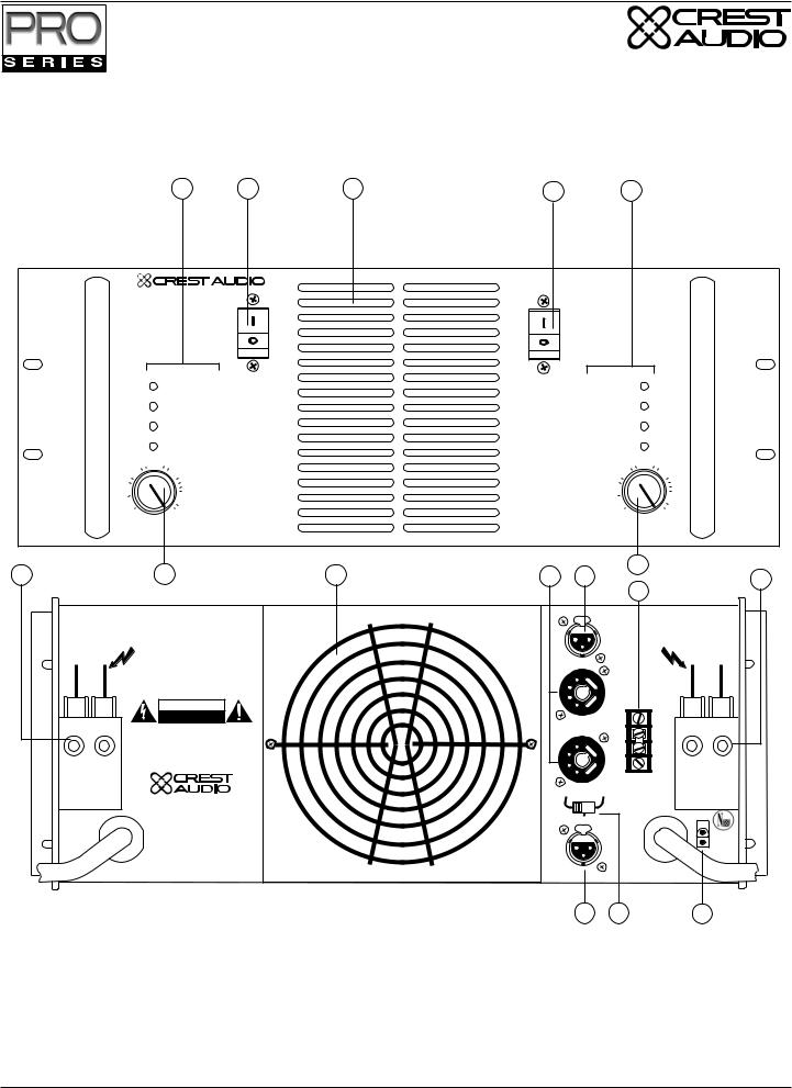
Model 8001 Features
1 |
2 |
3 |
8001 Professional Power Amplifier
Clip/Limit
Signal
Temp/DC
Active
-10 |
-6 |
-10 |
-6 |
-3 |
-3 |
||
-15 |
|
-15 |
|
-30 |
-1 |
-30 |
-1 |
|
|
||
-80 |
0dB |
-80 |
0dB |
|
Ch A |
|
Ch B |
4 |
5 |
6 |
7 |
|
|
|
|
8 |
9 |
|
IN B |
IN A |
|
|
|
|
|
|
|
|
PUSH |
PUSH |
|
CAUTION |
|
|
|
|
|
|
|
|
|
|
|
|
|
||
|
|
|
|
RISK OF ELECTRIC SHOCK |
|
|
|
||
|
|
|
|
DO NOT OPEN |
|
|
|
|
|
|
|
|
AVIS : RISQUE DE CHOC ÉLECTRIQUE |
NE PAS OUVRIR |
OUT A |
|
OUT A |
||
|
|
|
+ |
|
+ |
||||
|
|
|
WARNING TO REDUCE THE RISK OF FIRE OR ELECTRIC SHOCK DO NOT |
|
|||||
|
PIN 3+ |
|
|
|
|
||||
|
|
EXPOSE THIS EQU PMENT TO RAIN OR MOISTURE. |
|
|
|
||||
|
|
|
ATTENTION! POUR ÉVITER LE R SQUE D' NCENDIE OU DE CHOC |
+ |
|
+ |
|||
|
|
|
ÉLECTRIQUE, NE PLACEZ PAS CET APPAREIL SOUS LA PLUIE OU Á |
|
|||||
|
|
|
|
L HUMIDITÉ |
|
|
BRIDGE |
|
BRIDGE |
|
|
|
|
|
|
|
|
|
SIGNAL |
|
A |
|
|
USA ONLY |
|
|
|
|
GROUND |
|
|
|
|
MAXIMUM |
OUTPUT POWER |
|
|
LIFT |
|
|
PARALLEL |
|
|
+ |
|
+ |
|||
|
|
MODEL # |
INPUT CURRENT |
|
IN WATTS PER |
|
|||
|
|
|
|
OUT B |
|
OUT B |
|||
|
BRIDGE |
|
|
@ 120V, 60Hz |
|
CHANNEL, 2Ω |
|
||
|
|
|
|
|
|
|
|||
|
|
|
8001 |
30 AMPS |
|
1400W |
|
|
|
OUTPUT - CLASS 1 WIRING MAY BE USED
S EREO |
Designed & manufactured in the USA by: |
|
B
Crest Audio Inc.
100 Eisenhower Dr.
Paramus, New Jersey 07652 USA
1-Front Panel Channel Clip/Limit, Signal, Temp/DC, and Active LEDs. 2-Combination Circuit Breaker/Power Switch. 3-Heated Air Exhaust Grill. 4-Mode Select Switch. 5-XLR Input Connectors. 6-Crest Audio Octal Socket Accessory Connectors.
7-Channel A & B Attenuators. 8-Five-Way Output Binding Post Connectors. 9-Signal Ground Lift Barrier Strip.
Page 6 |
Crest Audio Pro Series Power Amplifiers |
Model 9001 Features
|
|
1 |
|
2 |
|
|
|
3 |
|
|
|
|
|
|
|
|
9001 Professional Power Amplifier |
||
|
|
Clip/Limit |
|
|
|
|
|
|
|
|
|
Signal |
|
|
|
|
|
|
|
|
|
Temp/DC |
|
|
|
|
|
|
|
|
|
Active |
|
|
|
|
|
|
|
|
-10 |
-6 |
-10 |
-6 |
|
|
|
|
|
|
-3 |
-3 |
|
|
|
|
|
||
|
-15 |
|
-15 |
|
|
|
|
|
|
|
-30 |
-1 |
-30 |
-1 |
|
|
|
|
|
|
|
|
|
|
|
|
|
||
|
-80 |
0dB |
-80 |
0dB |
|
|
|
|
|
|
|
Ch A |
|
Ch B |
|
|
|
|
|
4 |
5 |
6 |
|
7 |
8 |
9 |
|
10 |
|
PIN 3+ |
|
|
|
|
|
|
|
|
|
PUSH |
IN A |
|
|
A |
|
|
|
|
|
|
|
|
|
PARALLEL |
|
|
|
|
|
|
|
|
|
BRIDGE |
|
|
|
|
|
|
|
|
|
|
|
MODEL 9001 |
|
|
|
|
|
|
|
|
|
MAXIMUM OU PU |
|
|
|
|
|
|
|
|
|
POWER PER CHANNEL |
OUT A |
CAUTION |
|
|
|
|
|
|
|
4Ω 2200 WA |
S |
+ |
|
|
|
|
|
|
|
8Ω 1200 WA |
S |
|
|
PUSH |
IN B |
|
|
S EREO |
|
|
|
|
RISK OF ELECTRIC SHOCK |
|
|
|
|
|
|
|
|
DO NOT OPEN |
|
|
|
|
|
B |
|
|
|
|
|
|
|
|
|
|
SIGNAL |
|
BRIDGE |
AVIS : RISQUE DE CHOC ÉLEC RIQUE NE PAS OUVRIR |
|
|
|
|
|
|
|
GROUND |
|
+ |
WARNING TO REDUCE THE RISK OF F RE OR ELECTR C SHOCK DO NOT |
|
|
|
|
|
|
LIFT |
|
|
EXPOSE THIS EQUIPMENT TO RA N OR MOISTURE. |
|
|
|
|
|
|
DO NO OPERA E |
+ |
ATTENTION! POUR ÉVITER LE RISQUE D INCEND E OU DE CHOC |
|
|
|
|
|
|
|
ÉLECTR QUE, NE PLACEZ PAS CET APPAREIL SOUS LA PLUIE OU Á |
|||
|
|
|
|
|
|
WI HOU |
HIS |
OUT B |
L'HUMIDITÉ |
|
|
|
|
|
|
PRO EC IVE COVER |
|
|
|
Des gned & manufactured in the USA by:
NEXSYS |
Crest Audio Inc. |
OU PU |
|
SAMPLE |
100 Eisenhower Dr. |
|
Paramus, New Jersey 07652 USA |
11
1-Front Panel Channel Clip/Limit, Signal, Temp/DC, and Active LEDs. 2-Combination Circuit Breaker/Power Switch. 3-Heated Air Exhaust Grill. 4-XLR Input Connectors. 5-Air Intake/Fan Filter. 6-Channel Attenuators.
7-Mode Select Switch 8-Crest Audio Octal Socket Accessory Connectors.
9-Signal Ground Lift Barrier Strip. 10-Single-Screw Solderless Output Connectors. 11-NexSys Output Sample Connector
Crest Audio Pro Series Power Amplifiers |
Page 7 |
Model 10001 Features
1 |
2 |
3 |
2 |
1 |
10001 Professional Power Amplifier
|
Clip/Limit |
Clip/Limit |
|
|
Signal |
Signal |
|
|
Temp/DC |
Temp/DC |
|
|
Active |
Active |
|
|
-6 |
-10 |
-6 |
-10 |
-3 |
-3 |
|
-15 |
|
-15 |
-1 |
-30 |
-1 |
-30 |
|
|
|
||
-80 |
0dB |
-80 |
0dB |
|
Ch A |
|
Ch B |
4 |
5 |
|
6 |
7 |
8 |
|
5 |
|
|
4 |
|||||
|
|
|
|
|
|
|
9 |
|
|
|
|
|
PUSH |
IN A |
|
|
|
|
|
|
|
PIN 3+ |
|
- OUT B + |
|
|
|
|
|
|
+OUT A- |
|
CAUTION |
|
|
|
|
|
|
|
R SK OF ELEC RIC SHOCK |
|
|
|
|
||
|
DO NO |
OPEN |
|
|
|
|
|
AVIS : R SQUE DE CHOC ÉLEC RIQUE |
NE PAS OUVR R |
|
|
|
|
||
WARNING O REDUCE HE R SK O |
IRE OR E EC RIC SHOCK DO NO |
|
|
|
|
||
|
EX OSE HIS EQUI MEN |
O RAIN OR MO S URE |
|
|
|
|
|
A |
EN ION! OUR ÉVI ER E R SQUE D INCENDIE OU DE CHOC |
|
|
|
|
||
É EC RIQUE NE ACEZ AS CE A AREI |
SOUS A U E OU Á |
|
|
|
|
||
|
HUMIDI É |
|
|
|
|
|
|
|
Des gned & manufactured in the USA by: |
|
|
|
|
||
|
|
|
|
|
|
|
SIGNAL |
|
|
|
|
|
|
|
GROUND |
|
|
|
|
PARALLEL |
S EREO |
LIFT |
|
|
Crest Aud o Inc. |
|
|
|
|
|
|
|
100 E senhower Dr. |
|
|
|
|
|
|
|
Paramus, New Jersey 07652 USA |
|
|
|
|
||
|
|
|
|
|
BR DGE |
|
|
|
|
|
|
|
PUSH |
IN B |
NEXSYS |
|
|
|
|
|
|
|
|
|
|
|
|
|
|
|
OU PU |
|
|
|
|
|
|
|
SAMPLE |
AC MAINS INPUT |
|
|
|
|
|
AC MAINS INPUT |
|
CH. B |
|
|
|
|
|
|
CH. A |
8 |
10 |
11 |
1-Front Panel Channel Clip/Limit, Signal, Temp/DC, and Active LEDs. 2-Combination Circuit Breaker/Power Switch. 3-Heated Air Exhaust Grill. 4-Single-Screw Solderless Output Connectors. 5-Channel Attenuators. 6-Air Intake/Fan Filter. 7-Crest Audio Octal Socket Accessory Connectors. 8-XLR Input Connectors. 9-Signal Ground Lift Barrier Strip. 10-Mode Select Switch 11-NexSys Output Sample Connector
Page 8 |
Crest Audio Pro Series Power Amplifiers |
 Loading...