

Creative Live! Drive IR, Live! Drive IR SB0010 Quick Start Manual

Contents
Introduction .................................................................................................................1
System Requirements .................................................................................................. 2
Your Live! Drive IR ..................................................................................................... 3
Installing Hardware ..................................................................................................... 7
Using Your Live! Drive IR ........................................................................................ 11
Installing Software..................................................................................................... 14
Using the RemoteCenter Remote Control................................................................. 15
General Specifications............................................................................................... 16
Troubleshooting......................................................................................................... 17
Introduction
Connect Live! Drive IR to your Sound Blaster Live! audio card to get the best audio solution
available for your music, digital audio content creation, games, movies and other Internet
entertainment. The Live! Drive IR has a front panel, which allows you to connect commonly
used audio sources to external devices easily. It conveniently allows you to plug in your
microphone and headphones, and adjust the gain/volume from the front panel. Live! Drive IR
also provides MIDI, as well as, digital input and output connectors for your audio recording
and content authoring purposes. The infrared receiver on the Live! Drive IR lets you control
your PC and perform tasks (such as playing audio CDs and video CDs) remotely from the
comfort of your sofa or bed by using the Creative RemoteCenter remote control.
Live! Drive IR Quick Start SB0010

2 Live! Drive IR Quick Start SB0010
System
Requirements
The minimum system requirements for Live! Drive IR are:
❑ An installed Sound Blaster Live! (with an AUD_EXT expansion header)
❑ An available 5¼" PC drive bay
❑ Genuine Intel
®
Pentium® class processor:
166 MHz for Windows 95/98 or Windows Millennium Edition,
200 MHz for Windows NT 4.0 or Windows 2000
❑ Intel or 100% compatible motherboard chipset
❑ Windows 95, 98 or Millennium Edition, Windows NT 4.0 or Windows 2000
❑ 16 MB RAM for Windows 95/98 or Millennium Edition (32 MB RAM recommended),
32 MB RAM for Windows NT 4.0,
64 MB RAM for Windows 2000
❑ 160 MB of free hard disk space
❑ Headphones or amplified speakers (available separately)
❑ CD-ROM drive required for software installation
Live! Drive IR Quick Start SB0010 3
Your Live! Drive IR
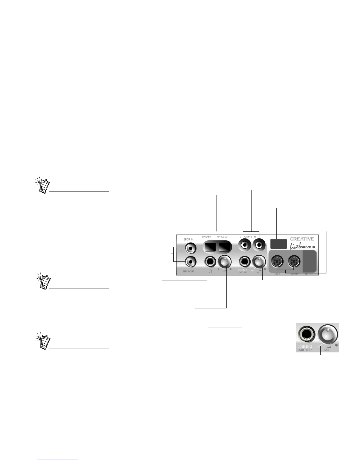
The front panel of your Live! Drive IR has these jacks, connectors and controls:
MIDI In/Out connectors
Connects to MIDI devices
using the Mini DIN-toStandard DIN cable provided
.
Line In 2/Mic In 2 selector
(Microphone Gain Control)
To switch to Line In 2, turn the knob
counter-clockwise over the Line In 2/Mic In
2 mode separator mark until a “click” sound
is heard. To switch back to Mic In 2, turn the
knob clockwise over the separator mark
until a “click” sound is heard. To control the
microphone gain, continue to turn
clockwise.
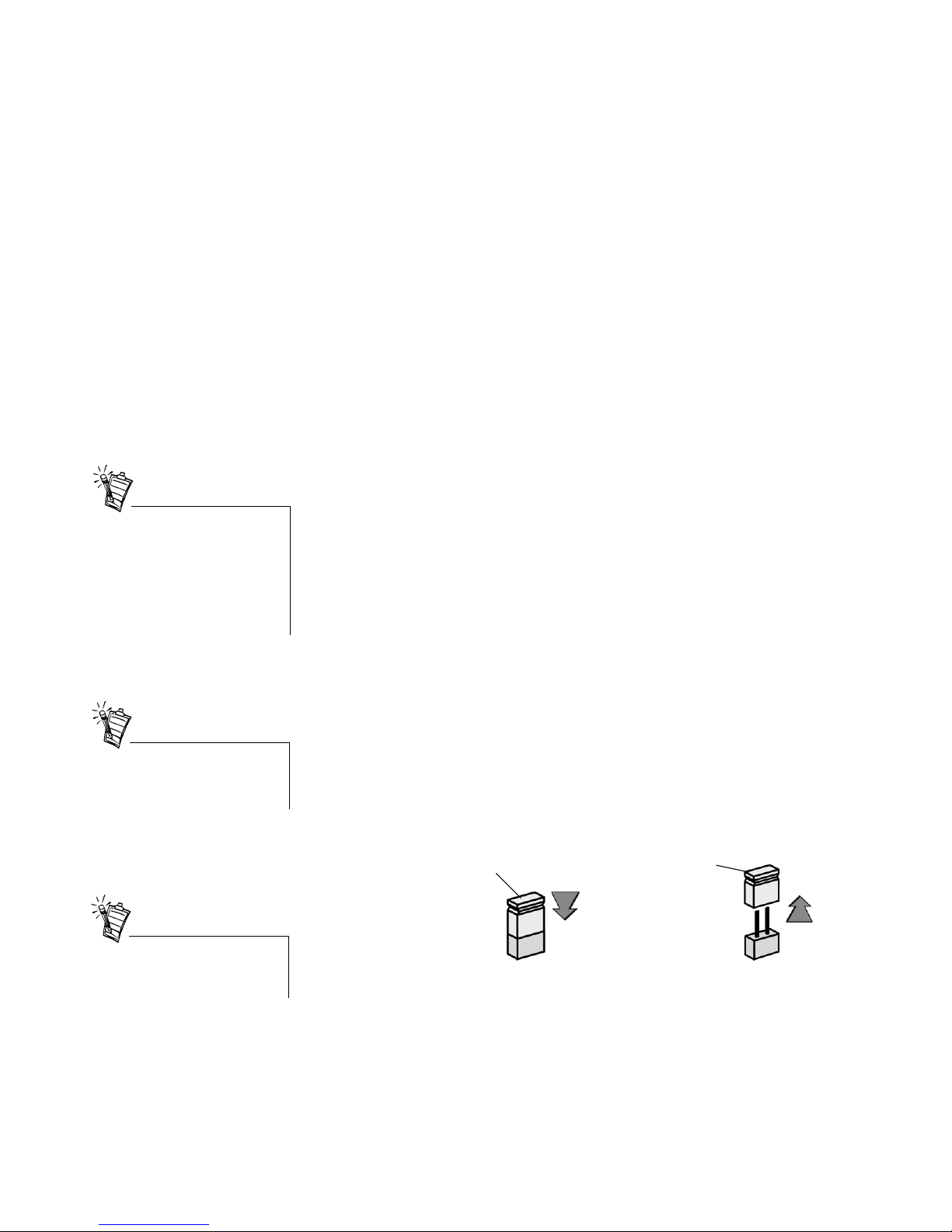
¼” Line In 2/Mic In 2 jack
Allows you to connect to a high-quality
dynamic microphone or audio device such
as an electric guitar, DAT, or MiniDisc player.
RCA Auxiliary In jacks
Connects to consumer equipment such as VCR,
TV and CD player, via RCA Auxiliary outputs.
Optical SPDIF In/Out connectors
Connects to digital audio devices
such as DAT and MiniDisc recorders,
via optical input/output.
Headphones Volume Control
Controls the headphones
output volume.
RCA SPDIF In/Out jacks
Connects to digital audio
devices such as DAT and
MiniDisc recorders, via
RCA input/output.
¼” Headphones jack
Allows you to connect to a pair of
high-quality headphones. Your
speaker output will be muted when
you connect the headphones.
Figure 1: Jacks, connectors and controls on the Live! Drive IR.
Line In 2/Mic In 2 mode
separator mark
Infrared Receiver
Lets you control your PC using the
RemoteCenter remote control.
If a particular INPUT source (for
example, Line In 2) is supported
by the Live! Drive IR as well as
the Digital I/O card, only the input
on the Live! Drive IR will be
enabled.
However, using the microphone
via the Line In 2/Mic In 2 input on
the Live! Drive IR will also
disable the Line In 2 input on the
Digital I/O card.
To connect to your existing
computer headphones and
microphone to the Live! Drive IR,
use the ¼” to 3.5mm adapter
provided.
It is recommended to lower the
gain level of the Mic In 2 jack to
the minimum before connecting a
microphone.

4 Live! Drive IR Quick Start SB0010
Switching
Audio Input Sources
On your Sound Blaster Live! and Live! Drive IR, two audio input sources may share a
connection. In such cases, only one of the input source can be enabled and used at any one time.
If your audio card has an I
2
S connector, you can use only either one of the following inputs at
any one time:
❑ I
2
S
❑ Line In 2 or Line In 2/Mic In 2
To switch the audio input source:
1. Click Start -> Programs -> Creative -> Sound Blaster Live! -> Surround Mixer.
2. On the Mixer deck (lower portion of Surround Mixer), click any of the audio input source
icon, and then select either the I
2
S In or Line In 2/Microphone 2 icon.
3. Click the red plus sign above the I
2
S In or Line In 2/Mic In 2 icon.
4. In the Other Advanced Controls dialog box, select the Enable Line In 2/Mic In 2 check
box to enable the Line In 2/Mic In 2 input source. Clear the check box to enable I
2
S In.
If your Live! Drive IR has Aux In 2 connectors, you can use only either one of the following
inputs at any one time:
❑ Aux In 2
❑ SPDIF In (Coaxial or Optical)
To switch the audio input source:
1. Click Start -> Programs -> Creative -> Sound Blaster Live! -> Surround Mixer.
2. On the Mixer deck (lower portion of Surround Mixer), click any of the audio input source
icon, and then select either the SPDIF In or Auxiliary 2 icon.
3. Click the red plus sign above the SPDIF In or Auxiliary 2 icon.
4. In the Other Advanced Controls dialog box, select the Enable Auxiliary 2 check box to
enable the Auxiliary 2 input source. Clear the check box to enable SPDIF In.
You need to install the software
first before you can switch audio
input sources.
However, if the SPDIF Bypass
feature and Aux In 2 are both
enabled, both the SPDIF In and
Aux In 2 channels will be
available.
For details on the SPDIF Bypass
feature, see “Digital I/O” on page
14.
Live! Drive IR Quick Start SB0010 5
Connecting Headphones There are two types of headphones which you can connect to the Live! Drive IR:
❑ Home audio or professional audio headphones, which are usually fitted with a ¼" stereo plug
.
❑ Personal stereo headphones, which are usually fitted with a 3.5mm stereo plug, such as those
used for portable audio players.
Connecting Microphone There are two types of microphone which you can connect to the Live! Drive IR:
❑ Dynamic microphone, which is usually fitted with a ¼" stereo plug, such as those used in
vocal performances
.
❑ Condenser microphone, which is usually fitted with a 3.5mm stereo plug, such as the
microphone bundled with Creative audio products.
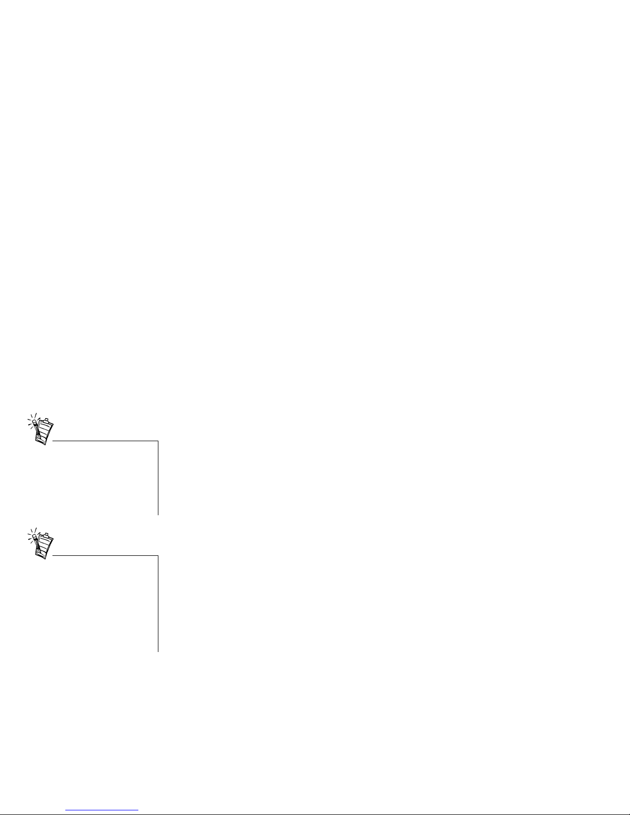
By default, Live! Drive IR is set for use with a condenser microphone. To use a dynamic
microphone, you must place the shunt (jumper cap) onto Jumper JP1 on the Live! Drive IR. See
Figure 4 on page 8 for the location of Jumper JP1 on the Live! Drive IR.
To listen to an analog source (e.g.
CD Audio) using headphones,
make sure that in Surround Mixer,
the recording source selected is
“What U Hear”. Otherwise, no
sound will be heard from the
headphones.
The shunt for Jumper JP1 can be
found together with the packet of
screws provided.
The Jumper JP1 may not be
available on certain models of
Live! Drive IR.
Shunt
Figure 2: Microphone jumper settings.
To use a dynamic
microphone,
place the shunt
onto Jumper JP1.
To use a condenser
microphone,
remove the shunt
from Jumper JP1
(default setting).
Jumper JP1
Jumper JP1
Shunt
6 Live! Drive IR Quick Start SB0010
Adjusting Headphones
Volume and Microphone
Gain
If your headphones and microphone are attached to the Live! Drive IR, the headphones volume
and microphone gain can be adjusted in two ways.
Using the Live! Drive IR
Control Knobs
On the front panel of the Live! Drive IR, turn the respective control knob:
❑ Counter-clockwise to decrease the headphones volume or microphone gain.
❑ Clockwise to increase the headphones volume or microphone gain.
Using Creative Surround Mixer To adjust the headphones volume:
1. Click Start -> Programs -> Creative -> Sound Blaster Live! -> Surround Mixer.
2. On the Mixer deck (lower portion of Surround Mixer), if the button below the VOL slider is
not highlighted, click it to unmute the output sound.
3. Adjust the VOL slider.
To adjust the microphone gain:
1. Click Start -> Programs -> Creative -> Sound Blaster Live! -> Surround Mixer.
2. On the Mixer deck (lower portion of Surround Mixer), click any of the audio input source
icon, and then select the Line In 2/Microphone 2 icon.
3. If the button below the Line In 2/Microphone 2 slider is not highlighted, click it to unmute
the audio input source.
4. Adjust the slider under the Line In 2/Microphone 2 icon.
It is recommended that you set the
headphones volume level and
microphone gain level to 75% in
Surround Mixer, and use the
control knobs on the Live! Drive
IR to make further adjustments.
Even if you turn the control knob
on the Live! Drive IR to the
maximum, your headphones will
have no sound if you set the
headphones volume level to 0% or
mute it in Surround Mixer. The
same applies for your
microphone.
Live! Drive IR Quick Start SB0010 7
Installing Hardware
To install your Live! Drive IR, you need to perform the following:
❑ Step 1: Prepare the System for Hardware Installation
❑ Step 2: Insert the Live! Drive IR into the System
❑ Step 3: Connect to the SB Live! Card
❑ Step 4: (Optional) Install the Digital DIN Metal Bracket (To connect to FPS2000, DTT2500
or DTT3500 digital speakers)
❑ Step 5: (Optional) Connect to the Digital I/O Card (Only if you have one)
❑ Step 6: Complete the Installation
Step 1:
Prepare the System for
Hardware Installation
1. Switch off your system and all peripheral devices.
2. Touch a metal plate on your system to ground yourself
and to discharge any static electricity, and then unplug
the power cord from the wall outlet.
3. Remove the cover from your system.
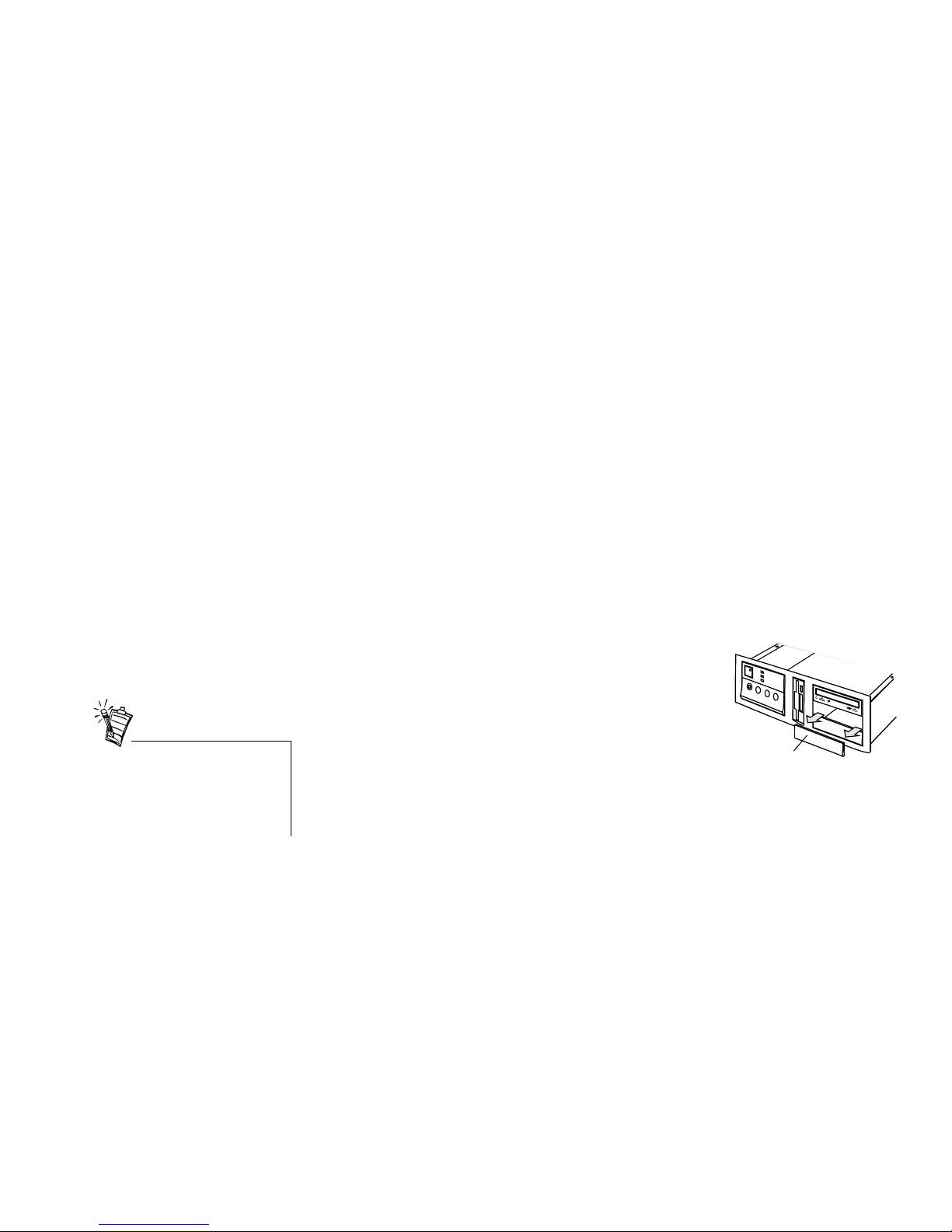
4. Remove the front panel cover from one unused 5¼"
drive bay.
Step 2:
Insert the Live! Drive IR
into the System
1. Pass the following cable ends from the inside of the casing through the vacant 5¼" drive bay,
and then leave the cables dangling halfway on the outside of the casing:
❑ Smaller end of the power splitter cable
❑ Dark grey flat cable end with a black circle near the connector
❑ (Optional) Any end of the light grey flat cable (if you want to connect to a Digital I/O
card from an earlier purchase)
❑ (Optional) Cable end of the Digital DIN metal bracket (if you want to connect to
FPS2000, DTT2500 or DTT3500 digital speakers)
Figure 3: Removing front panel cover.
Front panel cover
Place your CD-ROM/DVD-ROM
drive above the Live! Drive IR to
prevent dangling cables from the
front panel blocking access to the
drive tray.
 Loading...