

Page 1
Page 2

This machine has been engineered to our own rigid safety and performance
standards. It has been designed to comply with sanitation and health guidelines
recommended by the Automatic Merchandising Health-Industry Council (AMHIC)
and it conforms with all other NAMA safety recommendations.
This machine has been manufactured in accordance with the safety
standards of both Underwriter’s Laboratories and the Canadian Standards
Association. To maintain this degree of safety and to continue to achieve the level
of performance built into this machine, it is important that installation and
maintenance be performed so as to not alter the original construction or wiring and
that replacement parts are as specified in the Parts and Service Manual. Your
investment in this equipment will be protected by using this Operator’s Guide and
Parts and Service Manual in your operation, service and maintenance work. By
the
following prescribed procedures, machine performance and safety will be
preserved.
This Merchandiser is warranted for one (1) year against defective parts and
workmanship. Any part or parts which are proven to be defective within one (1)
year of the date of shipment will be repaired or replaced free of charge when the
defective part is returned, with transportation charges prepaid, to the destination
designated by the National Vendors Warranty Department.
This warranty applies only to the original purchaser of the Merchandiser
and is null and void if the Merchandiser is sold during the period of warranty.
This warranty does not apply to a) electrical components, wiring, or circuits
and/or for all mechanical parts or assemblies damaged as a result of operating the
Merchandiser at other than the design voltage and frequency specified on the
Electrical Rating Tag, or b) in event of vandalism, fire or negligence, or c)
incandescent lamps, neon lamps, fluorescent lamps, ballasts, starters or other
expendable items or d) when other manufactured components are installed in
National Vendors Merchandisers.
National Vendors is not responsible for any cost of service rendered or
repairs made by customer or its agents on Merchandiser or parts unless authorization to incur such expense has been given in writing by National Vendors prior to
incurring such expense.
THIS WARRANTY IS IN LIEU OF ALL OTHER WARRANTIES
EXPRESSED OR IMPLIED, INCLUDING WITHOUT LIMIT ATION, WARRANTIES OF MERCHANT ABILITY OR FITNESS FOR A PARTICULAR PURPOSE.
NA TIONAL VENDORS SHALL NOT BE RESPONSIBLE FOR CONSEQUENTIAL OR PUNITIVE DAMAGES. National Vendors neither assumes nor
authorizes any person to assume for it any obligation or liability in connection with
the sale of said equipment or any part thereof.
Page 3

HOT DRINK SETUP/PROGRAMMING GUIDE
TABLE OF CONTENTS
SPECIFICATIONS ................................................................................................ V
MAJOR PARTS ................................................................................................... VII
CONTROLS AND INDICATORS.......................................................................XI
I. LOCATION PREPARATION ........................................................................... 1
Electrical Power Requirements ........................................................................ 1
II. POSITIONING THE MERCHANDISER......................................................3
III. CONNECTING EVERYTHING ..................................................................... 3
1. Connect the Merchandiser to the Water Supply ......................................... 3
IV. FINAL MECHANICAL PREPARATION ..................................................... 4
1. Level the Merchandiser ............................................................................... 4
2. Mount the Base Plate .................................................................................. 5
3. Install the Water Filter Cartridge ................................................................. 6
Hydrolife Brand................................................................................................ 8
Installation ................................................................................................... 8
Removal ....................................................................................................... 8
Load the Optional Filter Paper ......................................................................... 9
(CONTINUED) ................................................................................................ 9
Replace The Cup Station And Grounds Bucket ............................................. 11
Install The Optional Coin Box Lock .............................................................. 11
Set Up And Load The Coin Mechanism........................................................ 1 2
Standard Coin Mechanism............................................................................. 1 2
MDB Coin Mechanism .................................................................................. 12
Fill The Tank .................................................................................................. 14
Fill The Canisters ........................................................................................... 14
Load Cups ...................................................................................................... 15
Cup Size(s) ..................................................................................................... 16
Set Prices ........................................................................................................ 17
Set Up The Menu ........................................................................................... 17
Establish Time Of Day Vending Periods........................................................ 17
Customize The Drink Recipes .......................................................................17
Set Up Custom Messages ...............................................................................1 7
Posivend™ .....................................................................................................17
V . ADJUSTMENTS AND MINOR MAINTENANCE ...................................... 19
1. Empty the Bill Stacker .............................................................................. 19
2. Adjust the Water Valves ............................................................................ 19
3. Adjust the Air Pressure .............................................................................. 20
4. Install Canisters ........................................................................................20
5. Adjust the Cup Mechanism ....................................................................... 2 1
VIEW A...................................................................................................... 21
VIEW B...................................................................................................... 21
6. Set Up the Menu Assembly....................................................................... 22
GETTING AROUND ............................................................................................. 23
THE SERVICE KEYPAD ....................................................................................... 23
THE SELECTION SWITCH P ANEL ..................................................................... 23
PROGRAMMING THE HOT DRINK ................................................................... 23
THE DISPLA YS ......................................................................................................24
THE FUNCTION KEYS ......................................................................................... 25
OTHER KEYS ........................................................................................................ 25
TABLE OF CONTENTS
November, 2002 i 6700001
Page 4

HOT DRINK SETUP/PROGRAMMING GUIDE
III. CONTROL PANEL SWITCHES EXPLAINED ........................................ 26
PROGRAMMING PROCEDURES........................................................................ 28
THE SUPERVISOR MODE ................................................................................... 28
GAIN ACCESS TO THE SUPERVISOR MODE................................................... 29
ENTER A NEW SUPERVISOR CODE.................................................................. 29
ENTER A FREEVEND CODE ............................................................................... 29
THE SUPERVISOR MODE ................................................................................... 29
LOCK OR UNLOCK MODE OR PAYOUT KEYS ............................................... 30
SET PRINTER OR DEX OPTIONS ....................................................................... 30
LOCK OR UNLOCK DA TA CLEARING ACCESS ............................................. 31
SELECT DISPLA Y LANGUAGE........................................................................... 31
SELECT COIN MECHANISM AND OPTIONS ................................................... 32
SELECT BILL VALIDA T OR AND OPTIONS ....................................................... 33
BILL LIST OPERATION ........................................................................................33
SELECT MONET AR Y OPTIONS.......................................................................... 35
SELECT CARD READER AND OPTIONS .......................................................... 37
SET UP WINNER MODE ...................................................................................... 38
ADV ANCED OPTIONS.......................................................................................... 38
SET UP THE MUG DISCOUNT ............................................................................ 39
SET THE PRINTER BAUD RATE ........................................................................ 39
LOCK OR UNLOCK SELECTIONS .....................................................................40
DISABLE SELECTIONS IN THE MERCHANDISER ......................................... 40
ASSIGN CUP SIZES T O SELECTIONS................................................................ 41
(SUPERVISOR MODE ONLY) .............................................................................. 41
SET UP A HOT DRINK .......................................................................................... 42
WHIPPER OPTIONS .............................................................................................. 43
DIFFERENCES(OPTIONS) ................................................................................... 44
VIEW OR SET THE HOT WATER TANK TEMPERA TURE .............................. 44
SET UP LOW TEMPERATURE DISPENSING..................................................... 45
TSET UP LOW POWER SETTINGS ..................................................................... 45
SET THE RA TIO OF CHOCOLATE IN CAPPUCCINO....................................... 47
SET THE BREWER RINSE TIME INTERVAL ..................................................... 47
THE BOWL RINSE TIME...................................................................................... 48
TURN POSIVEND™ ON OR OFF ........................................................................ 48
OPTIONAL OR MANDATORY POSIVEND™ .................................................... 49
SET UP THE POSIVEND™ ANTI-JACKPOT TIMER ......................................... 49
VIEW NUMBER OF MUG VENDS ...................................................................... 50
VIEW MACHINE ID NUMBER ............................................................................ 50
VIEW CUP RING CYCLES RELATED TO POSIVEND™.................................. 50
VIEW TIMES NO CUP WAS DETECTED AFTER A CUP RING CYCLED....... 51
VIEW HOME SWITCH USAGE RELATED TO POSIVEND™ ..........................51
VIEW POSIVEND™ LAST RECORDED CALIBRATION.................................. 52
VALUE ....................................................................................................................52
VIEW POSIVEND™ AVERAGE CALIBRATION VALUE ................................. 52
CONTINUE ............................................................................................................. 52
CLEAR T ANK ERRORS AND FILL THE T ANK ................................................. 52
SET THE MACHINE TYPE CONFIGURATION CODE ...................................... 53
SET UP THE CUP ONLY OPTION (SUPERVISOR MODE ONLY).................... 55
SET UP DELIVERY DOOR OPTIONS (SUPERVISOR MODE ONLY) .............55
6700001 ii November, 2002
Page 5

HOT DRINK SETUP/PROGRAMMING GUIDE
COLLECTING DRY PRODUCT GRAM THROWS............................................. 56
DRY PRODUCT WEIGHT AND THROW TIME FACTOR Y DEFAUL T
SETTINGS .............................................................................................................. 57
CAPPUCCINO RECIPE ......................................................................................... 59
CAPPUCCINO ........................................................................................................ 59
MOTOR SPEED BY LOCATION .......................................................................... 60
HINTS ................................................................................................................... 60
CAFFÉ LA TTE RECIPE......................................................................................... 64
CAFFÉ LA TTE........................................................................................................ 64
ENTER THE SUPERVISOR CODE ...................................................................... 64
SET THE MACHINE TO VEND A LARGE "D" SELECTION ............................64
SET UP YOUR SELECTION ................................................................................. 65
EUROPEAN CAPPUCCINO ................................................................................. 65
RECONFIGURE THE MACHINE ......................................................................... 65
COLLECTING W A TER THROWS ........................................................................ 67
EUROPEAN CAPPUCCINO RECIPE ...................................................................67
WA TER THROW DEF AULT TIMES AND VOLUMES ....................................... 68
SET PRICES FOR INDIVIDUAL SELECTIONS .................................................. 69
SET THE PRICE FOR A CUP ONLY ..................................................................... 70
SET ONE PRICE FOR THE ENTIRE MACHINE ................................................ 70
SET ONE PRICE FOR ALL REGULAR SIZE DRINKS ....................................... 70
SET ONE PRICE FOR ALL LARGE SIZE DRINKS ............................................ 71
SET THE TIME....................................................................................................... 71
SET THE DA Y OF THE WEEK ............................................................................. 71
SET THE DATE AND YEAR ................................................................................. 72
SET TIME-OF-DA Y INHIBITED VENDING ........................................................ 72
SET TIME-OF-DA Y DISCOUNT VENDING........................................................ 73
SET TIME-OF-DA Y FREE VENDING .................................................................. 73
TIME INTER V AL EDITING................................................................................... 74
ST AND BY.............................................................................................................. 75
SELECT A ST ANDBY MESSAGE ........................................................................ 76
SELECT AN OUT-OF-SER VICE MESSAGE........................................................ 77
SELECT A FREEVEND MESSAGE ...................................................................... 77
EDIT CUSTOM MESSAGES................................................................................. 78
THE END OF MESSAGE CHARACTER ............................................................. 78
ENTERING YOUR MESSAGE ............................................................................. 79
THE CHARACTER SET ........................................................................................ 79
TEST VEND SELECTIONS AND VERIFY CREDIT ADDED ............................ 80
TEST THE DISPLA Y.............................................................................................. 80
TEST THE CUP MECHANISM ............................................................................. 81
TEST THE AUT OMA TIC DOOR (OPTIONAL) ................................................... 81
TEST THE WHIPPERS .......................................................................................... 81
TEST THE AIR COMPRESSOR............................................................................ 82
TEST THE BREWER ............................................................................................. 82
RINSE ALL MIXING BOWLS............................................................................... 83
VIEW FREEVEND SALES BY TIME INTER VAL ............................................... 83
VIEW DISCOUNT SALES BY TIME INTER VAL ................................................ 84
VIEW FREE VENDS.............................................................................................. 84
VIEW WINNERS.................................................................................................... 85
VIEW TIME DA TA ................................................................................................. 85
November, 2002 iii 6700001
Page 6

HOT DRINK SETUP/PROGRAMMING GUIDE
VIEW TOT AL UNP AID SALES ............................................................................. 87
VIEW TOT AL UNP AID VENDS............................................................................ 87
VIEW NUMBER OF TEST VENDS...................................................................... 87
VIEW SALES DATA BY PRICE ............................................................................87
SET FREEVEND OPTIONS ..................................................................................88
NO MONEY REQUIRED....................................................................................... 88
VIEW MACHINE ID NUMBER ............................................................................ 89
VIEW NON-RESETT ABLE SALES AND VEND DAT A...................................... 89
VIEW DATA THREE DIFFERENT WA YS ............................................................ 89
RINSE THE BREWER ........................................................................................... 90
FILL THE T ANK ..................................................................................................... 90
TEST VARIOUS SENSORS AND SWITCHES..................................................... 91
P A YOUT COINS ..................................................................................................... 91
VIEW TOT AL PAID SALES .................................................................................. 92
VIEW CARD READER PAID SALES ..................................................................92
VIEW TOT AL PAID VENDS ................................................................................. 92
CLEAR ALL RESETTABLE DATA ....................................................................... 93
CLEAR PAID SALES DA TA ONL Y ...................................................................... 93
VIEW AMOUNT IN COIN BOX ........................................................................... 93
VIEW AMOUNT IN VALIDATOR ........................................................................ 94
VIEW DIAGNOSTIC MESSAGES ........................................................................ 94
DOWNLOAD DATA T O A PDCD.......................................................................... 98
CHANGE MACHINE ID NUMBER...................................................................... 99
VIEW THE WA TER T ANK TEMPERATURE....................................................... 99
VIEW THE CURRENT SOFTWARE VERSION NUMBER ................................ 99
VIEW THE SELECTION MACHINE TYPE ....................................................... 100
VIEW THE SELECTION CONFIGURATION ..................................................... 100
SANITATION ......................................................................................................101
Basics ...........................................................................................................101
How Do I Sanitize? ......................................................................................101
Chemicals ..................................................................................................... 101
Heat
Food-Contact Parts .......................................................................................1 03
Non Food-Contact Parts ............................................................................... 104
OVERALL CLEANING .....................................................................................104
Preventive Maintenance Cleaning ............................................................... 1 04
APPENDIX A. THE OPTIONAL PRINTER .................................................... A1
APPENDIX B. THE INFRARED MUG/CUP SENSOR ................................. B3
Indicator Light ............................................................................................... B3
Cleaning ........................................................................................................ B3
Calibration ..................................................................................................... B4
APPENDIX C. DEX/UCS INTERFACE OPERATION................................... C7
Select Data Transfer Method......................................................................... C7
Download Data.............................................................................................. C 7
APPENDIX C. DEX/UCS INTERFACE OPERATION.................................. C7
APPENDIX D. MODIFY CANISTER TO VEND 12 OZ. CUPSD9
APPENDIX E. CLEAN THE HOT WATER TANK...................................... E11
APPENDIX F. THE FREE VEND KEYSWITCH OPTION ........................ F13
Using The Free Vend Key Switch ................................................................ F13
6700001 iv November, 2002
Page 7
HOT DRINK SETUP/PROGRAMMING GUIDE
SENIHCAMLLAOTNOMMOCSNOITACIFICEPS
SNOISNEMID hgih)mc381("27
THGIEW )gk5.512(sbl574
STNEMERIUQERRETAW )aPk8.731(isp02:muminiM
ERUTAREPMETTNEIBMA )C°5(F°14:muminiM
GNITAREPO
TNEMNORIVNE
SEITICAPACPUC
)ETAMIXORPPA(
SEITICAPACRETSINAC
)ETAMIXORPPA(
ediw)mc18("23
peed)mc27("5.82
)aPk2.155(isp08:mumixaM
)C°23(F°09:mumixaM
ylnoesuroodniroF
569-spuczo5
508-)tauqs(spuczo7
537-spuczo52.8
077-)tauqs(spuczo9
096-spuczo01
066-spuczo21
)ylno436ledoM(sbl31-eeffocwerbhserF
sbl2-eeffocyrdezeerF
)ylno436ledoM(sbl9-facedwerbhserF
sbl2-facedyrdezeerF
sbl5.1)yrdezeerf(aeT
sbl01-etalocohC
)sbl4(sbl7.6-)etutitsbusragusro(puoS
sbl11-raguS
sbl5.4-renethgiL
SNOITPOTCUDORP
SPECIFICATIONS
werBhserF076ledoM :noitarugifnoCdradnatS
aetyrdezeerF
snoitceles
:snoitarugifnoClanoitpO
noitcelesretawtoH
noitcelespuoS
RO
deirDezeerF876ledoM :noitarugifnoCdradnatS
eeffocyrdezeerF
facedyrdezeerF
aetyrdezeerF
snoitceles
:snoitarugifnoClanoitpO
noitcelesretawtoH
noitcelespuoS
RO
)dnuorg-erp(eeffocwerbhserF
facedyrdezeerfROwerbhserF
"ylnopuc"dna,etalocohctoh,oniccuppac,osserpsE
tnemidnocetutitsbusraguS
"ylnopuc"dna,etalocohctoh,oniccuppac,osserpsE
tnemidnocetutitsbusraguS
November, 2002 Page - v 6700001
Page 8
HOT DRINK SETUP/PROGRAMMING GUIDE
SNOITPO roodyreviledcitamotuA
)dedis1(tikellirgesaB
)dedis3(tikellirgesaB
kcolxobnioC
tikretnirpataD
redaerdractibeD
tikgnipirtsrooD
tikretlifretaweruprevE
tikretlifretawonuC
tikretlifretawefiL-ordyH
tikreppihwpuoS
yekdnakcolroodecAxelF
yekdnakcolroodnaV
hctiwsyekdneveerF
tiketutitsbusragusropuoS
yartesnirtneidergnI
dneVisoP
tiknoitcelesretawtoH
)ylno436ledoM(
roodtenibacrof
LACIRTCELE CAstloV511
ztreH06
spmA21
esahpelgniS
0006-CRTSRAM
0003NORTNIOC
MSINAHCEMNIOC
SROTADILAVLLIB eslup1MFVSRAM
laires3MFVSRAM
eslupAKAM
OCNIOC
BDM
LACIRTCELE CAstloV042-022
ztreH05
spmA01
Wk2
esahpelgniS
MSINAHCEMNIOC ecafretnimsinahcemniocevitucexE
)deunitnoc(SENIHCAMLLAOTNOMMOCSNOITACIFICEPS
)llat"4(seveelsnoisnetxeretsinactneidergnino-panS
)tikhctiwsdlohpuc(rosnescinortcelegum/puC
rewerbrof)llorrepsdnev0005(tikrepapretliF
tniap"yargderutxeT"ro"etihwderutxeT"foeciohC
SENIHCAMTLOV511OTEUQINUSNOITACIFICEPS
SEIROSSECCADNASNOITPO
)V42(VX0106-CRTSRAM
)V42(400-XPSUledoMxulnoC/akaM
)V42(FL-2039ledoMsrotpeccAnioC
SENIHCAMTLOV042-022OTEUQINUSNOITACIFICEPS
SEIROSSECCADNASNOITPO
6700001 Page - vi November, 2002
Page 9
HOT DRINK SETUP/PROGRAMMING GUIDE
POINT OF
K
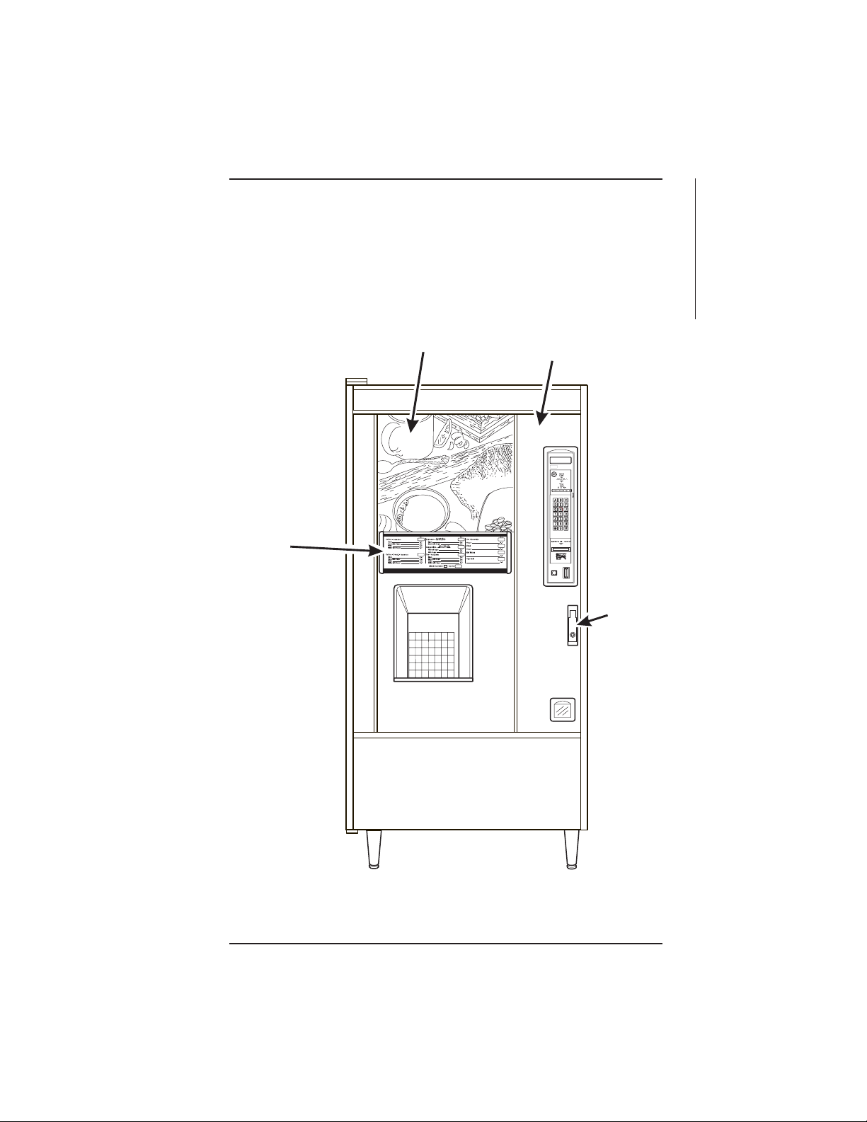
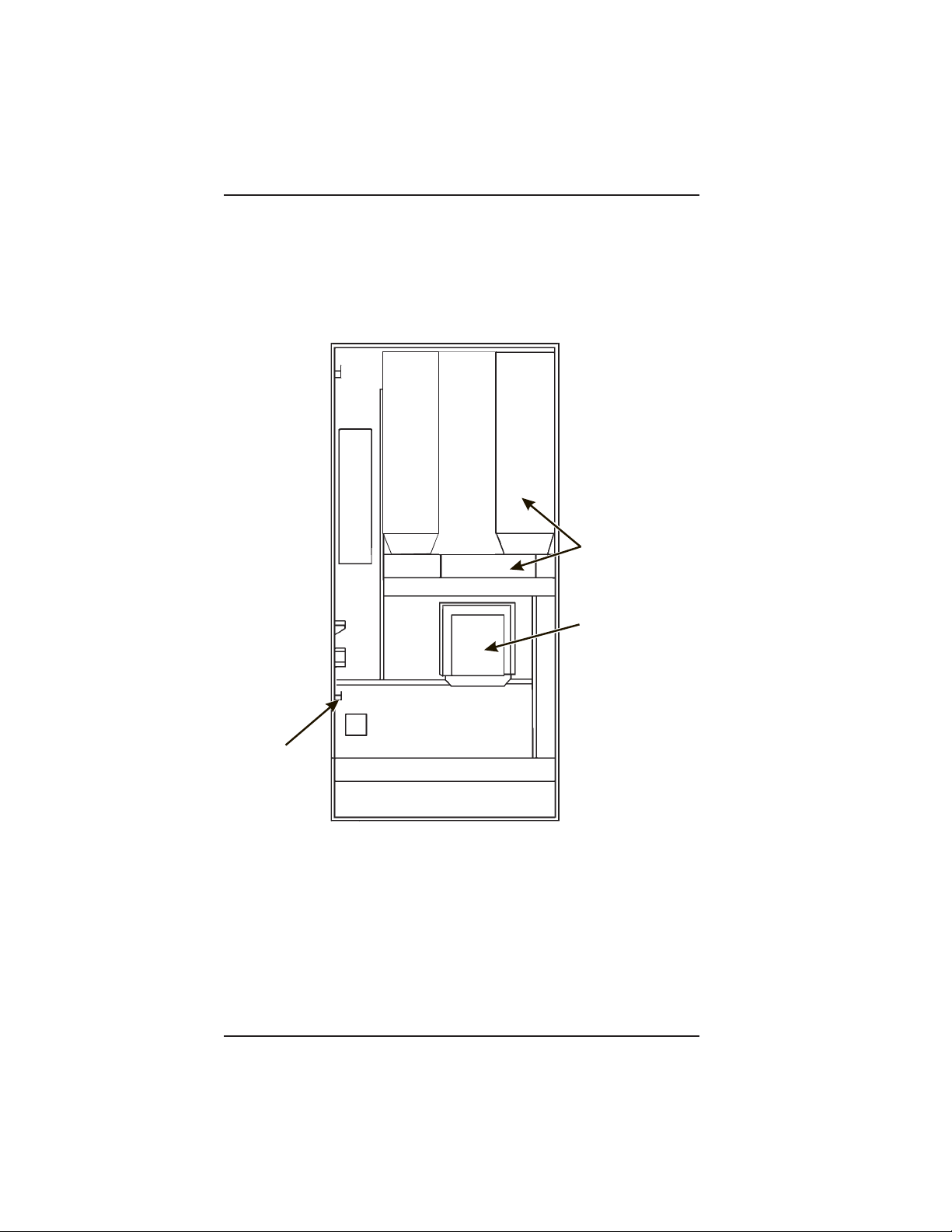
MAJOR PARTS
The diagrams on the following pages will acquaint you with the major parts of the Hot Drink
merchandiser. For more detailed information, please consult your PARTS MANUAL. If you
do not have a PARTS MANUAL, contact National Vendors Parts Department.
MENU
ASSEMBLY
PURCHASE
PHOTO
˜
EXTERIOR
DOOR
ASSEMBLY
˜
CRANE
NATIONAL VENDORS
MAJOR PARTS
LOC
FRONT OF MERCHANDISER
November, 2002 Page - vii 6700001
Page 10
HOT DRINK SETUP/PROGRAMMING GUIDE
CUP MECHANISM
TURRET ASSEMBLY
AND MOTOR AND PCB
ASSEMBLY
DELIVERY DOOR
LOCK BAR
ASSEMBLY
636p0048
FRONT VIEW OF MERCHANDISER
BACK SIDE OF MERCHANDISER DOOR
6700001 Page - viii November, 2002
Page 11
HOT DRINK SETUP/PROGRAMMING GUIDE
ASSEMBLY
T
SERVICE LIGHT
D
E
C
A
F
C
O
F
F
E
E
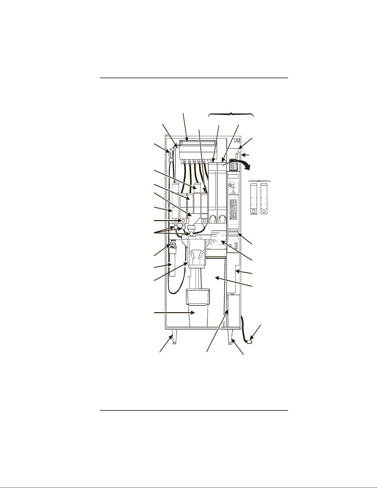
WATER TANK
RINSE
HOSE
ASSEMBLY
SUGAR
CANISTER
LIGHTENER
CANISTER
WO INGREDIENT
CHUTE
CHOCOLATE
CANISTER
SOUP OR SUGAR
SUBSTITUTE
CANISTER
DRINK WHIPPER
ASSEMBLY
FILTER & VALVE
HEAD ASSEMBLY
WATER FILTER
CARTRIDGE
CUP DELIVERY
ASSEMBLY
ASSEMBLY
ASSEMBLY
F.D. TEA
CANISTER
( OPTIONAL )
F.B. DECAF
CANISTER
F.B. COFFEE
CANISTER
NATIONAL VENDORS
CRANE
MONETARY
PANEL
ASSEMBLY
CABINET
( OPTIONAL )
F.D. CANISTERS
C
D
O
E
F
C
F
A
E
F
E
BILL
ACCEPTOR
(OPTIONAL)
BREWER
(OPTIONAL)
COIN
MECHANISM
GROUNDS
PAIL
LIQUID
WASTE
PAIL
LEVELER ASSEMBLY
LEG, HINGE, &
COIN BOX
ASSEMBLY
POWER CORD
&
PLATE ASSEMBLY
LEG & LEVELER
MERCHANDISER CABINET INTERIOR
November, 2002 Page - ix 6700001
Page 12
HOT DRINK SETUP/PROGRAMMING GUIDE
˜
˜
I
O
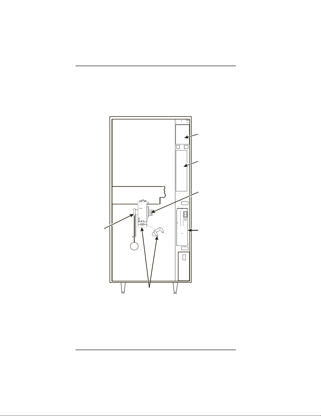
MAIN
CONTROLLER
PCB ASSEMBLY
INTERFACE
BOARD
EXHAUST
FAN
BRACKET
ASSEMBLY
OVERFLOW
SWITCH
ASSEMBLY
OPTIONAL INFRARED
CUP/MUG SENSOR
OR
Posi-Vend
636P0047
POWER
PANEL
ASSEMBLY
MERCHANDISER CABINET INTERIOR
6700001 Page - x November, 2002
Page 13
HOT DRINK SETUP/PROGRAMMING GUIDE
CONTROLS AND INDICATORS
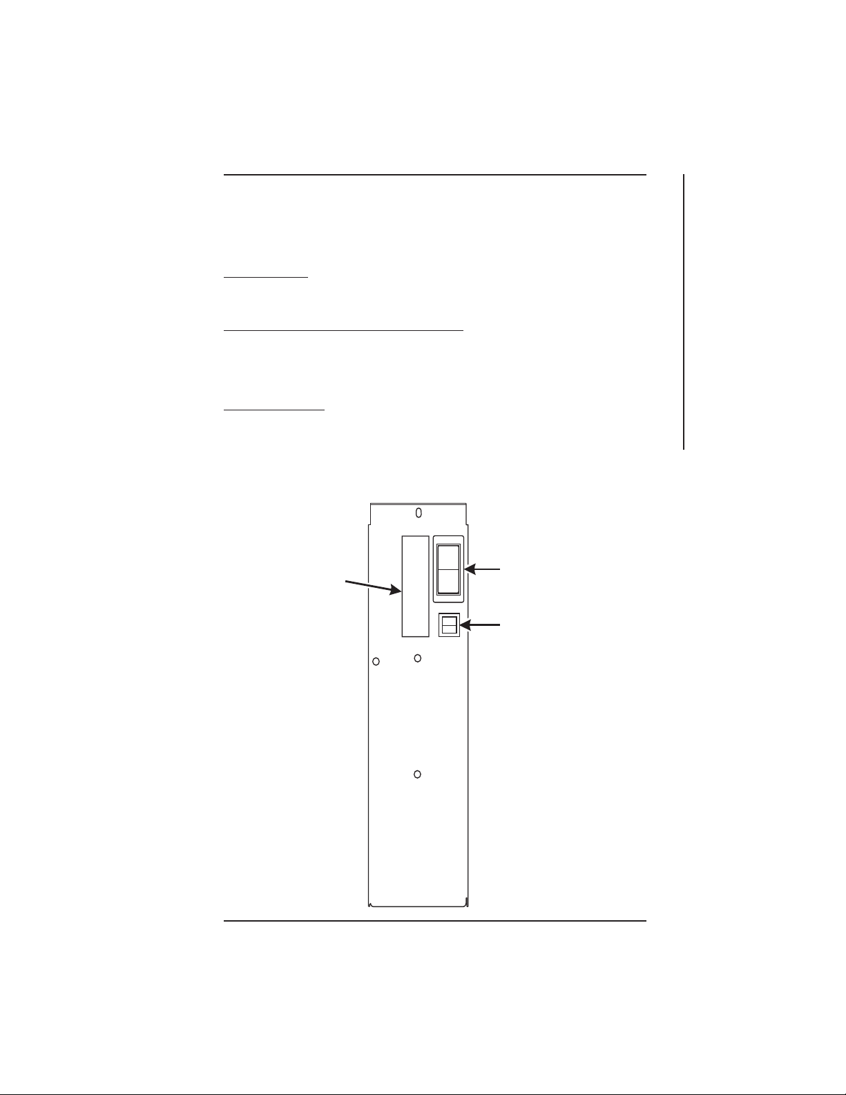
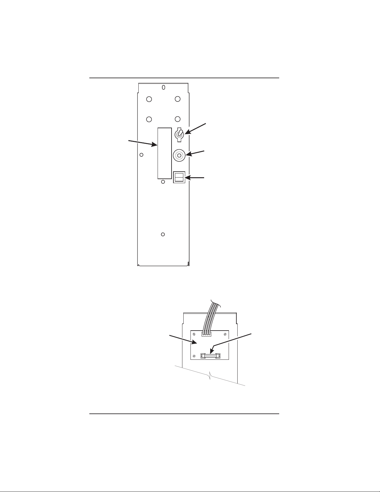
POWER PANEL. You may have one of three power panels, depending upon where you
live. The controls are fundamentally the same, however.
Circuit Breakers. Circuit breakers protect the merchandiser against failures in the power
supply or any of the electrical components. If a circuit breaker trips and cannot be reset,
consult your troubleshooting manual.
Back Side of U.S./ Canada Power Control Panel. The circuit board mounted on the rear
of the U.S. and Canadian power control panel is a dc power supply for the coin
mechanism. A fuse protects the board circuitry in the event of a coin mechanism solenoid
failure. If the coin mechanism is not working, check this fuse. If the fuse is blown, a bad
coin mechanism solenoid could be at fault.
Main Power Switch. This is the main ON/OFF switch for the merchandiser.
To protect against electrical shocks and possible damage to the
machine, turn this switch OFF when performing any maintenance on the merchandiser.
WARNING
I
MAIN
POWER
LABEL
O
SWITCH
ELECTRONICS
BREAKER
CONTROLS AND INDICATORS
626P0005
November, 2002 Page - xi 6700001
Page 14
HOT DRINK SETUP/PROGRAMMING GUIDE
1
E
P
MAIN
POWER
SWITCH
MAIN
LABEL
ON
OFF
CIRCUIT
BREAKER
LOW VOLTAGE
CIRCUIT BREAKER
626P0006
POWER CONTROL PANEL
(U.S./CANADA)
TOP
DC POWER
SUPPLY PCB
FOR 110V COIN MECH
BACK SIDE OF U.S./CANADA POWER CONTROL PANEL
6700001 Page - xii November, 2002
˜
AGC
FUS
1 AM
Page 15
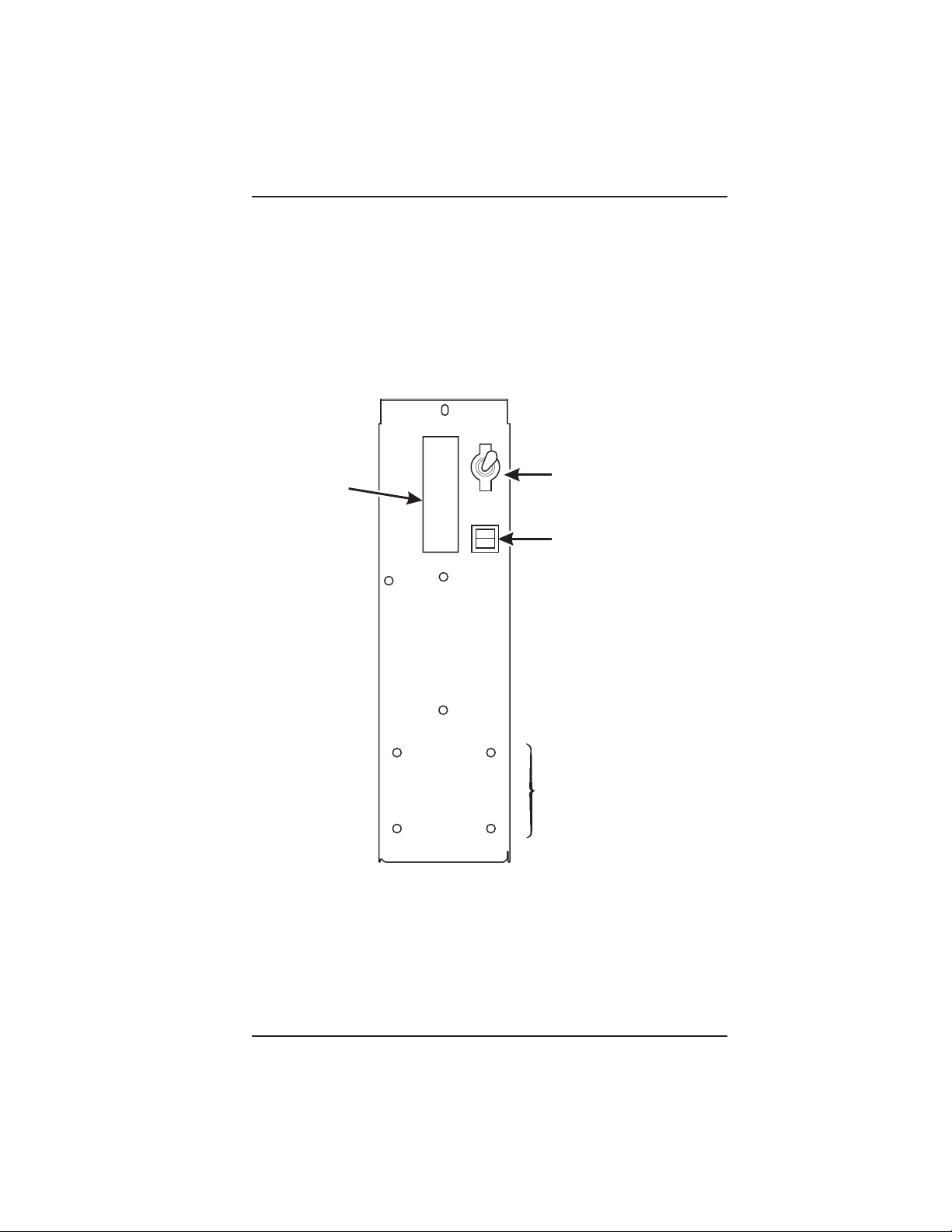
L
ABEL
R
HOT DRINK SETUP/PROGRAMMING GUIDE
ON
MAIN POWER
OFF
SWITCH
ELECTRONICS
CIRCUIT BREAKE
MOUNTING STUDS
FOR MEXICO ONLY
POWER CONTROL PANEL
(U.K. / MEXICO)
November, 2002 Page - xiii 6700001
Page 16
HOT DRINK SETUP/PROGRAMMING GUIDE
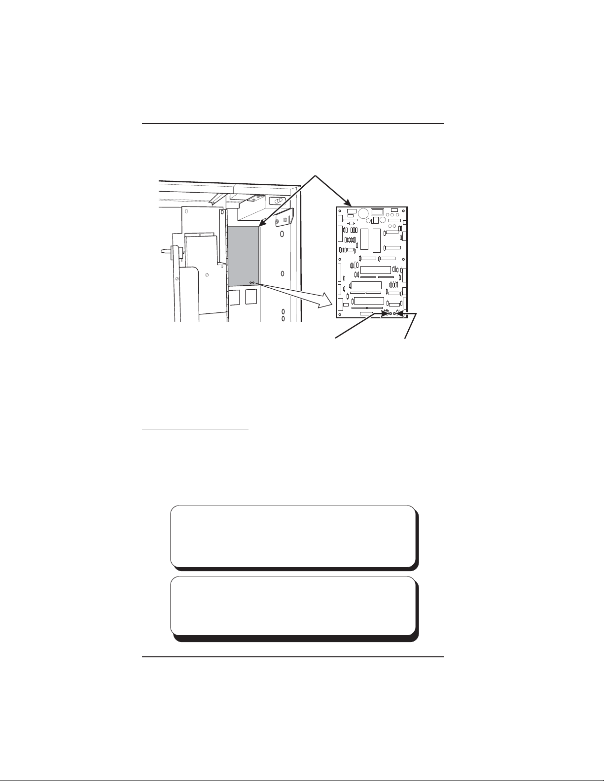
MAIN CONTROLLER
T
PCB ASSEMBLY
LED1LED2
POWER ON
(LED 1)
FLASHING
HEARTBEA
(LED 2)
MAIN CONTROLLER PCB DISPLAY
Main Controller PCB Display. This display consists of two light emitting diodes (LED)
mounted on the controller PCB.
POWER ON When lit, this red LED indicates electrical power is applied to
(LED 1) the controller PCB.
HEARTBEAT When flashing, this red LED indicates that the controller PCB is
(LED 2) active, and the software is operating.
NORMAL CONDITIONS:
When the merchandiser is operating normally, you should see a
steady red POWER ON indicator. The red HEARTBEAT indicator
should be flashing with a balanced on/off pattern (on for the same
length of time that it is off).
ERROR CONDITIONS:
If an error is present, the red HEARTBEAT indicator will flash with an
unbalanced on/off pattern (on longer than it is off). The error(s) can be
viewed under the DIAGNOSTICS mode.
6700001 Page - xiv November, 2002
Page 17
HOT DRINK SETUP/PROGRAMMING GUIDE
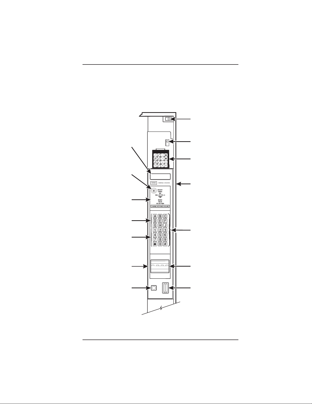
E
E
H
I
HIGH VOLTAG
INTERLOCK
SWITCH
MESSAGE
DISPLAY
LOW VOLTAG
DOOR SWITC
SERVICE
FREE VEND
KEYPAD
KEYSWITCH
(OPTIONAL)
CABINET
NSTRUCTION
PLATE
LETTERS
A-H,J
NUMERALS
SELECTION
SWITCH
1-9, *,0, #
MONETARY
PANEL
COIN
RETURN
BUTTON
BILL
ACCEPTOR
(OPTIONAL)
COIN
INSERT
MONETARY PANEL
November, 2002 Page - xv 6700001
Page 18

HOT DRINK SETUP/PROGRAMMING GUIDE
High Voltage Interlock Switch (U.S./ Canada). When the cabinet door is open, this
switch turns off the optional fan and bean light (if equipped), and turns on the service light.
High Voltage Interlock Switch (International). When the cabinet door is open, this
switch turns off all high voltage to the cabinet. Pulling the switch out restores high voltage
for maintenance purposes.
Low Voltage Door Switch. Informs the controller software of the main door open or
closed status.
Message Display. This is how the merchandiser communicates with the outside world.
Customers can see messages about how much money they have put into the merchandiser. The message display also tells customers when a selection is sold out and when
vending is free, inhibited, or discounted. The message display shows you what you are
doing when you program the merchandiser, and can show you what is wrong if there is
a failure.
Free Vend Keyswitch. This allows someone (other than maintenance people) to set the
merchandiser to free vend without opening the door.
Selection Switch Panel. The customer uses these switches to make selections. Also,
maintenance people may use this switch panel during programming and other support
modes.
Coin Return Button. Pressing this button returns any coins that have been paid into the
merchandiser prior to a vend.
Bill Acceptor (Optional). Accepts bills in various denominations, depending upon the
type of bill validator, and how the machine is configured.
Service Keypad. The service keypad is located at the top of the monetary panel. It gives
service personnel the means to program, retrieve data from, and view diagnostic
information about, the merchandiser.
SERVICE KEYPAD
6700001 Page - xvi November, 2002
Page 19

HOT DRINK SETUP/PROGRAMMING GUIDE
Current (Amps
INITIAL SETUP
I. LOCATION PREPARATION
After your machine is unpacked and placed near its permanent location, you need
to make sure you have the proper electrical and water service.
ELECTRICAL POWER REQUIREMENTS
This merchandiser needs electrical power as shown in the following table.
Each merchandiser should have its own electrical circuit.
Country Volts Frequency (Hz)
Canada 115 60 15
France 230 50 10
Germany 230 50 10
United Kingdom 230 50 10
United States 115 60 15
1. Check the Power Outlet
This merchandiser is supplied with a service cord for the country of use and is terminated in a grounding type plug. The wall receptacle used for this merchandiser must be
properly polarized, grounded, and of the correct voltage. Operating the merchandiser
from a source of low voltage will VOID YOUR WARRANTY. Each merchandiser should
have its own electrical circuit and that circuit should be protected with a circuit breaker or
fuse conforming to local regulations.
Voltage Check - Place the leads of a voltmeter across the LINE (LIVE) and
NEUTRAL terminals of the wall receptacle. The voltmeter should indicate 110-130
volts ac for 120 volt, 60 Hz locations, or 220-240 volts ac for 230 volt, 50 Hz
locations.
Polarity Check - Place the leads of a voltmeter across the LINE (LIVE) and
GROUND terminals of the wall receptacle. The voltmeter should indicate 110-130
volts ac for 120 volt, 60 Hz locations, or 220-240 volts ac for 230 volt, 50 Hz
locations.
NOTE
Power Requirements
Noise Potential Check - Place the leads of a voltmeter across the NEUTRAL and
GROUND terminals of the wall receptacle. The voltmeter should indicate 0 volts
ac. A measurement greater than 1.5-2.0 volts ac could result in problems for the
merchandiser's electronic circuitry caused by electrical noise.
Any deviation from these requirements could result in unreliable performance from your
merchandiser.
6700001 Page - 1 November, 2002
Page 20

HOT DRINK SETUP/PROGRAMMING GUIDE
WATER REQUIREMENTS
The best type of water for coffee brewing is normal hard (tap) water. If your location
has chemically softened water, you should do one of the following things:
• Have a non-softened supply line run to the merchandiser
• Contact your local water filter supplier for information and suggestions
Well water can also be used in the Hot Drink Machine. However, you should
have it checked for levels of carbonates and alkalies. Contact your water filter
supplier if these values are relatively high.
What is the Water Pressure at Your Location?
It should be no less than: 10 psi ( 69.0 KPa) at 1/2 gallon/minute
And no more than: 80 psi (522.0 KPa) at 1/2 gallon/minute
If you're not sure about the pressure and flow rate, check with your water company.
What to do With the Water Supply Line:
Locate the supply line at the rear of your merchandiser.
Equip the line with a shut-off valve.
Flush the water supply line before connecting it to the merchandiser. A minimum of
five gallons is usually required before connecting the merchandiser to the supply line.
DO NOT flush the merchandiser water system. If you do, you might introduce water
line contaminants into the merchandiser.
November, 2002 Page - 2 6700001
Page 21

HOT DRINK SETUP/PROGRAMMING GUIDE
II. POSITIONING THE
MERCHANDISER
You can position this merchandiser anywhere in a bank of machines. It can even be
placed on the end flush against a side wall. Be sure you leave enough room in front
of the merchandiser for the door to move freely.
BE SURE THE REAR OF THE MERCHANDISER IS AT LEAST 6" AWAY
FROM THE WALL. THIS WILL ALLOW WARM MOIST AIR TO BE VENTED
OUT OF THE MACHINE'S INTERIOR.
THIS MACHINE IS ONLY RATED FOR INSTALLATION IN AN
INDOOR LOCATION.
WARNING:
III. CONNECTING EVERYTHING
1. Connect the Merchandiser to the Water Supply:
a. You will need the following:
• A coil of copper tubing with outside diameter of 3/8 inch (9.5 mm) or greater.
The appropriate plastic tubing may be substituted. The tubing must be long
enough to reach from the water source to your machine with enough left over
to form a loop about 2 feet (60 cm) in diameter. This will allow you to move the
machine without straining the water line.
• A 3/8 inch (9.5 mm) flare fitting.
b. Connect the merchandiser to your water supply.
2. Connect the Merchandiser to the Electrical Power Supply:
Power inside the merchandiser is controlled by the main power switch, located on the
power panel.
a. Make sure the main power switch is OFF.
b. Connect the merchandiser’s power cord to your wall outlet.
6700001 Page - 3 November, 2002
Page 22
HOT DRINK SETUP/PROGRAMMING GUIDE
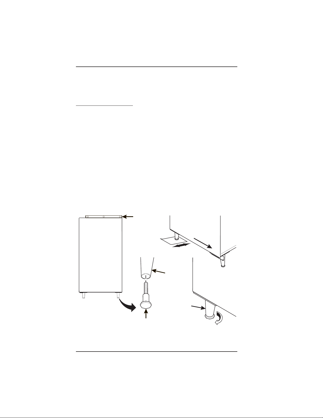
SPIRIT LEVEL
LEVELER
IV. FINAL MECHANICAL
PREPARATION
1. Level the Merchandiser:
a. Place a spirit level on the top front edge of the cabinet with the door fully
closed. Adjust the front legs only until the cabinet is reasonably level.
b. Hold the door open about 4 inches.
HAVE AN ASSISTANT HOLD THE MERCHANDISER WHILE
YOU ADJUST THE LEG LEVELERS.
c.Adjust the back legs so that the back leg leveler on the hinge side is off the
floor just enough so a piece of paper can slide under it with only a bit of
resistance.
d. For proper weight distribution on all four legs, raise the back leg on the hinge
side by unscrewing the leveler 1½ turns.
You may need to use pliers or channel locks to loosen the leg
levelers.
WARNING
NOTE
FRONT
LEG
November, 2002 Page - 4 6700001
LEG
LEFT REAR
LEG
1-1/2 TURNS
Page 23
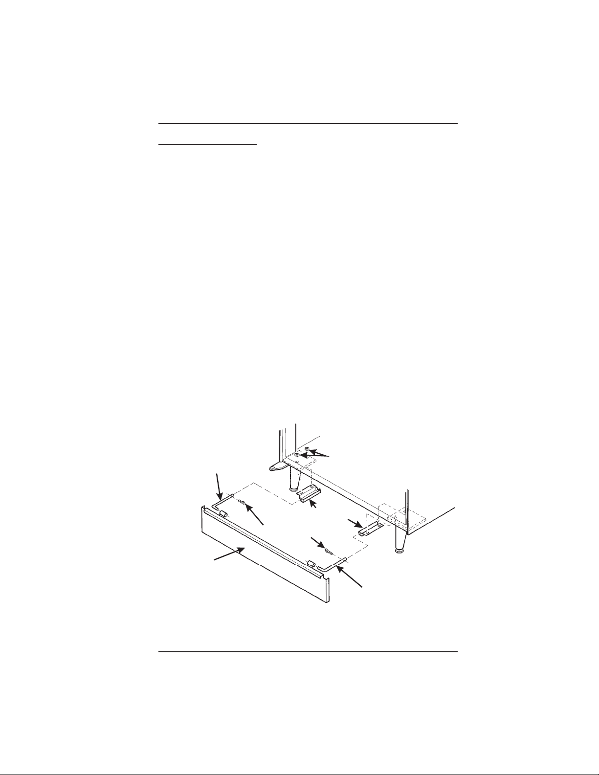
2. Mount the Base Plate:
B
HOT DRINK SETUP/PROGRAMMING GUIDE
DO NOT MOVE THE CABINET WHILE HEX
HEAD SCREWS AND/OR CARRIAGE
BOLTS ARE LOOSENED. THE CABINET
WOULD BECOME UNSTABLE AND LIKELY TO TIP AND CAUSE INJURY.
a. Remove the pail(s) from the inside of the merchandiser.
b. Remove the floor liner from the inside of the merchandiser.
c. Remove the two caps as shown.
d. Loosen the left leg assembly carriage bolts and nuts to allow mounting a base plate
bracket.
e. Secure one of the base plate brackets to the leg assembly using the two carriage
bolt. Tighten the carriage bolts and nuts.
f. Loosen the right leg assembly hex head screws to allow mounting the other base
plate bracket.
g. Secure the other base plate bracket to the right leg assembly using the two hex
head screws. Tighten the hex head screws.
h. Insert the short arms of the slides into the hinged tabs of the base plate. Position
the slide so the notch near the short arm is on the bottom side.
i. Insert the long arms of the slides into the base plate brackets.
j. Insert and secure a cotter pin through the hole in the back of each of the slides.
k. Push the base plate toward the merchandiser cabinet. The front tabs of the base
plate brackets should seat in the notches in the long arms of the slides.
l. Replace the caps, liner, and pail(s) removed previously.
WARNING
CAPS
SLIDE - L.H.
BASE PLATE BRACKET
COTTER PIN
ASE PLATE
ASSEMBLY
SLIDE - R.H.
6700001 Page - 5 November, 2002
Page 24
HOT DRINK SETUP/PROGRAMMING GUIDE
1
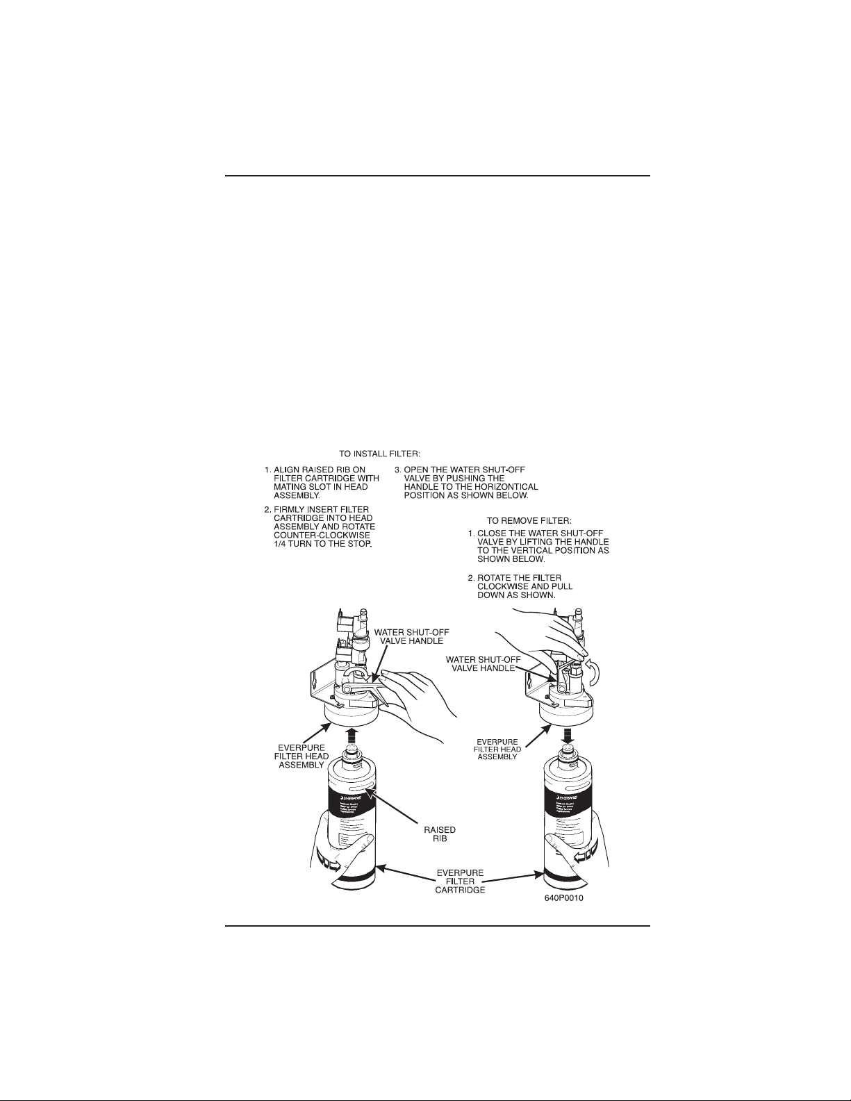
3. Install the Water Filter Cartridge:
IF YOUR MERCHANDISER HAS THE WATER FILTER OPTION, IT CANNOT BE OPERATED WITHOUT A PROPERLY
INSTALLED WATER FILTER CARTRIDGE. If you do not have
the water filter option, continue with "Fill the Tank".
CUNO BRAND ...
Check the water filter installation record.
There is a place to write the vend number
on the cartridge. The cartridge is effective
for a maximum of 64,000 7 oz. vends,
56,000 8 oz. vends, 50,000 9 oz.
vends, or 37,000 12 oz. vends. Local
conditions may require more fre-
quent replacement.
CUNO FILTER
FILTER
LOCKING
TAB
TO INSTALL
THE FILTER:
1. INSERT NEW FILTER,
ROTATE COUNTERCLOCKWISE UNTIL
FILTER LOCKING TAB
SNAPS INTO GROOVE
AS SHOWN.
HEAD ASSEMBLY
GROOVE
NOTE
. CLOSE THE WATER SHUT
-OFF VALVE BY TURNING
THE KNOB TO THE
HORIZONTAL POSITION
AS SHOWN.
WATER
SHUT-OFF
KNOB
TO REMOVE FILTER:
2. LIFT THE FILTER
LOCKING TAB,
ROTATE FILTER
CLOCKWISE AND
PULL DOWN AS
SHOWN.
CUNO
FILTER
FILTER
LOCKING
TAB
November, 2002 Page - 6 6700001
Page 25
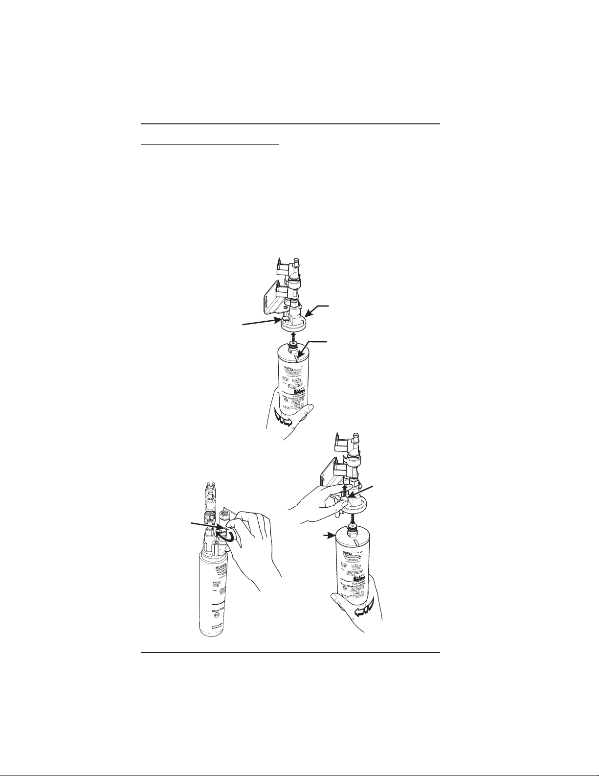
EVERPURE BRAND ...
HOT DRINK SETUP/PROGRAMMING GUIDE
Check the water filter installation record. There is a place to
write the vend number on the cartridge. The cartridge is
effective for a maximum of 26,000 7 oz. vends, 22,000 8 oz.
vends, 20,000 9 oz. vends, or 15,000 12 oz. vends. Local
conditions may require more frequent replacement.
National Vendors recommends that you do the following procedure the first time you
fill the tank in your EuroDrink merchandiser:
a. Remove the small inner "O" ring from the filter cartridge.
b. Install the filter cartridge.
c. Turn on the water at its source, and perform the tank filling procedure.
d. Turn off the water at its source, remove the filter cartridge, and replace the
"O" ring.
e. Install the filter cartridge.
NOTE
6700001 Page - 7 November, 2002
Page 26
HOT DRINK SETUP/PROGRAMMING GUIDE
E
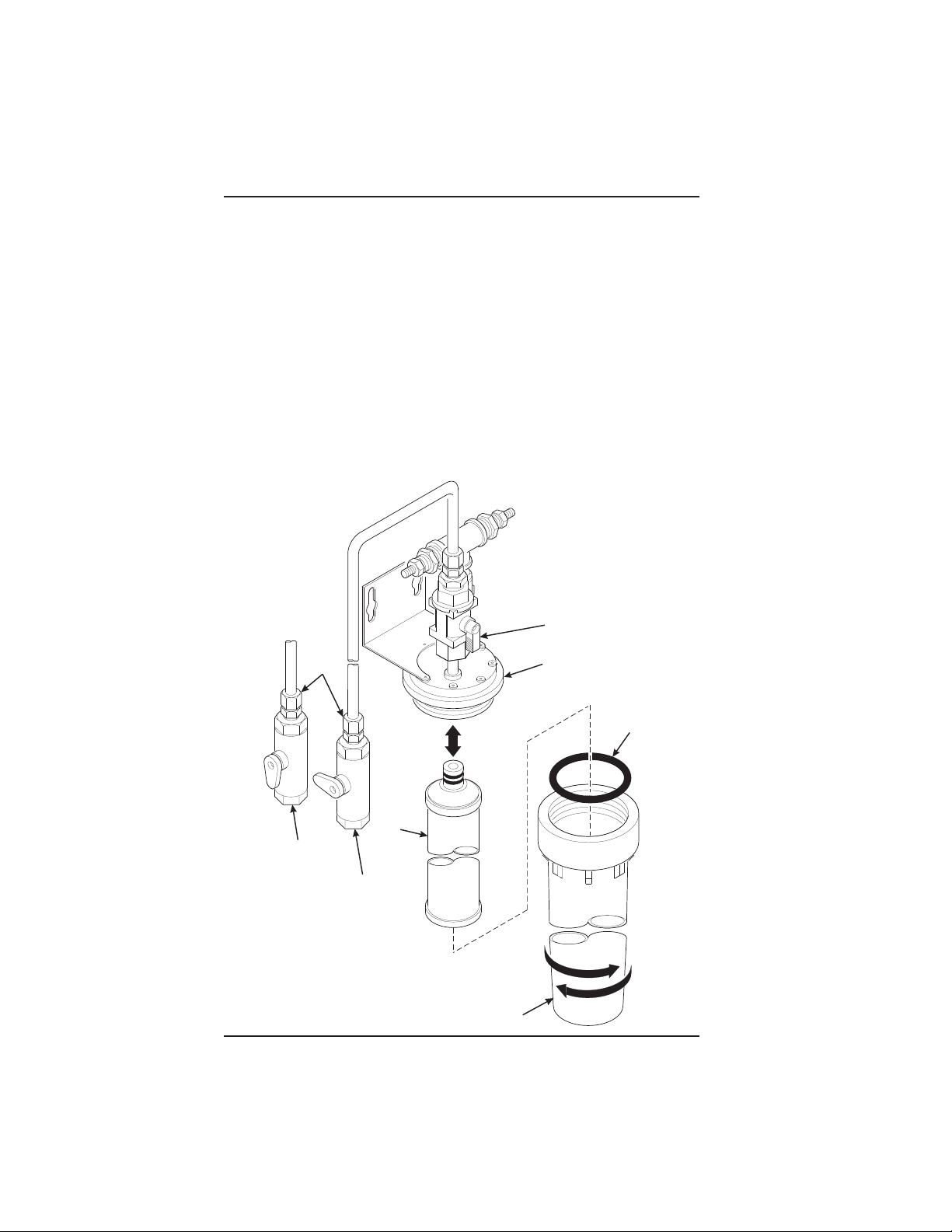
HYDROLIFE BRAND
INSTALLATION:
1. Place the filter inside the canister. Be sure the o-ring is seated in the canister just
below the threads.
2. Screw the canister and filter assembly onto the filter head until it comes to a stop.
3. Open the water valve on the inlet line by rotating the handle to the vertical position
as shown.
REMOVAL
1. Close the valve on the inlet line by rotating the handle into the horizontal position
as shown.
2. Relieve water pressure by performing two or three water throws (see the
programming section).
3. Unscrew the filter and canister assembly from the filter head. Remove the filter
from the canister.
OPEN
POSITION
INSTALL
HYDROLIFE
FILTER HEAD
O-RING
REMOV
OPEN
POSITION
VALVE
CLOSED
POSITION
FILTER
CANISTER
November, 2002 Page - 8 6700001
Page 27

HOT DRINK SETUP/PROGRAMMING GUIDE
H
R
TO BREWER
PAPER
PINION GEAR SHAFT
G
L
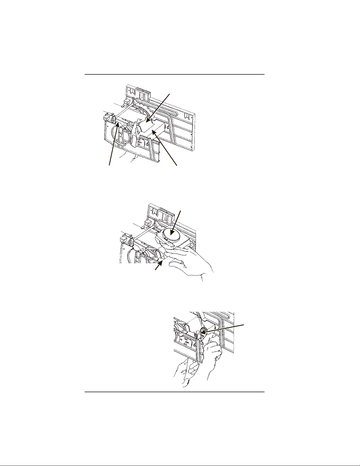
4. Load the Optional Filter Paper:
a. Be sure the main power switch is in the OFF position.
b. Remove the cup station and grounds bucket.
c. Remove the paper holder cover by turning the fastener a quarter turn to the left.
d. Insert a roll of paper into the paper holder. Route the free end of the paper to the
brewer as shown.
e. Replace the cover on the paper holder. Secure it by turning the fastener a quarter
turn to the right.
f. Feed paper over swing arm assembly and underneath pinion gear shaft.
PAPER
OLDER
g. Feed paper through the paper guides.
h. Raise the basket housing assembly and feed paper over the lip of the paper
mechanism housing.
GUIDES
SWING ARM
ASSEMBLY
IP OF PAPER MECHANISM HOUSING
PAPER
ROLL
COVER
FASTENE
BASKET HOUSIN
ASSEMBLY
PAPER MECHANISM HOUSING
It may be necessary to reach underneath the brewer between
the paper mechanism housing and swing arm assembly to
6700001 Page - 9 November, 2002
push paper over the lip of the paper mechanism housing.
NOTE
(CONTINUED)
Page 28
HOT DRINK SETUP/PROGRAMMING GUIDE
R
Y
G
SWING ARM ASSEMBLY
LIP OF PAPER MECHANISM HOUSIN
PAPER MECHANISM HOUSING
i. Reach underneath the brewer between the paper mechanism housing and basket
housing assembly and push paper into the top of the paper mechanism housing
between paper rollers.
BASKET HOUSING ASSEMBL
PAPER MECHANISM HOUSING
j. Reach underneath the brewer and pull paper roller to the right.
k. Pull paper down between the paper rollers.
l. Release the paper roller.
m. Place the main power switch in the
ON position.
n. Test the brewer to be sure the
paper feeds properly:
PAPER
ROLLE
November, 2002 Page - 10 6700001
Page 29
HOT DRINK SETUP/PROGRAMMING GUIDE
1. On the maintenance keypad, press , then press until the
display shows
2. Press to test each brewer position:
Keep away from the brewer mechanism while it is operating.
Coming into contact with moving parts could injure you.
BREW TEST.
WARNING
BREW 'R BREW The brewer is in the BREW position.
BREW 'R FLIP The brewer is in the FLIP position.
BREW 'R HOME The brewer is in the HOME position.
3. Make sure the filter paper feeds properly without jamming.
4. Replace the cup station and grounds bucket.
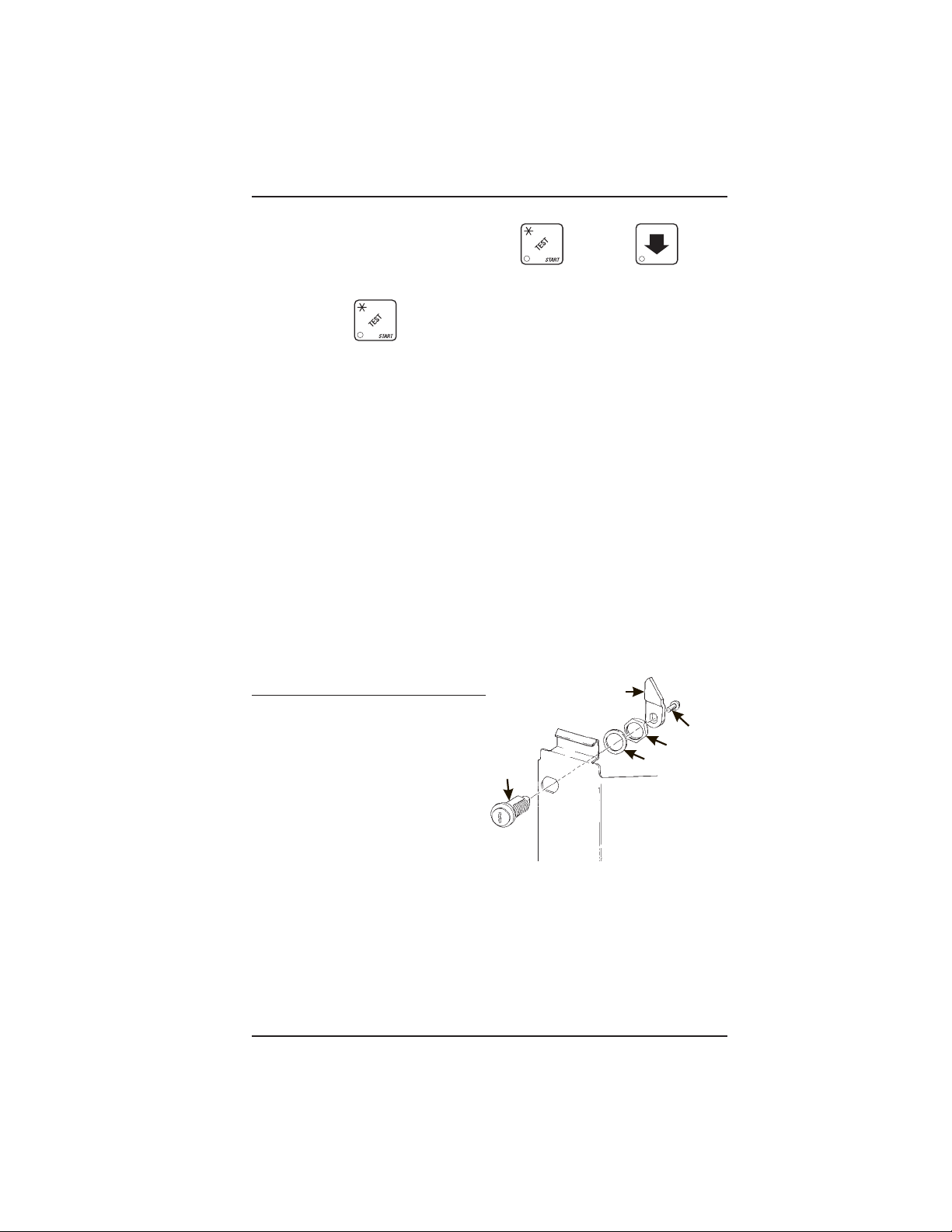
5. Install the Optional Coin Box Lock
a. Install the lock cylinder, washer, and nut in
the order shown.
b. Tighten the nut.
c. Install the lock bar as shown,
and secure with the screw.
LOCK
CYLINDER
LOCK BAR
SCREW
NUT
WASHER
6700001 Page - 11 November, 2002
Page 30
HOT DRINK SETUP/PROGRAMMING GUIDE
6. Set Up and Load the Coin Mechanism
Standard Coin Mechanism
Setting the Quarter Switch. If your coin mechanism is not a MARS TRC 6000, skip
this procedure and begin LOADING THE COIN MECHANISM.
a. Flip down the front of the coin
mechanism as shown, and set the quarter switch.
Load the Coin Mechanism.
a. Open the cabinet door and the monetary door.
b. Insert coins into their respective tubes until each tube has been filled.
c. Inspect the tubes for shingled coins and correct if necessary.
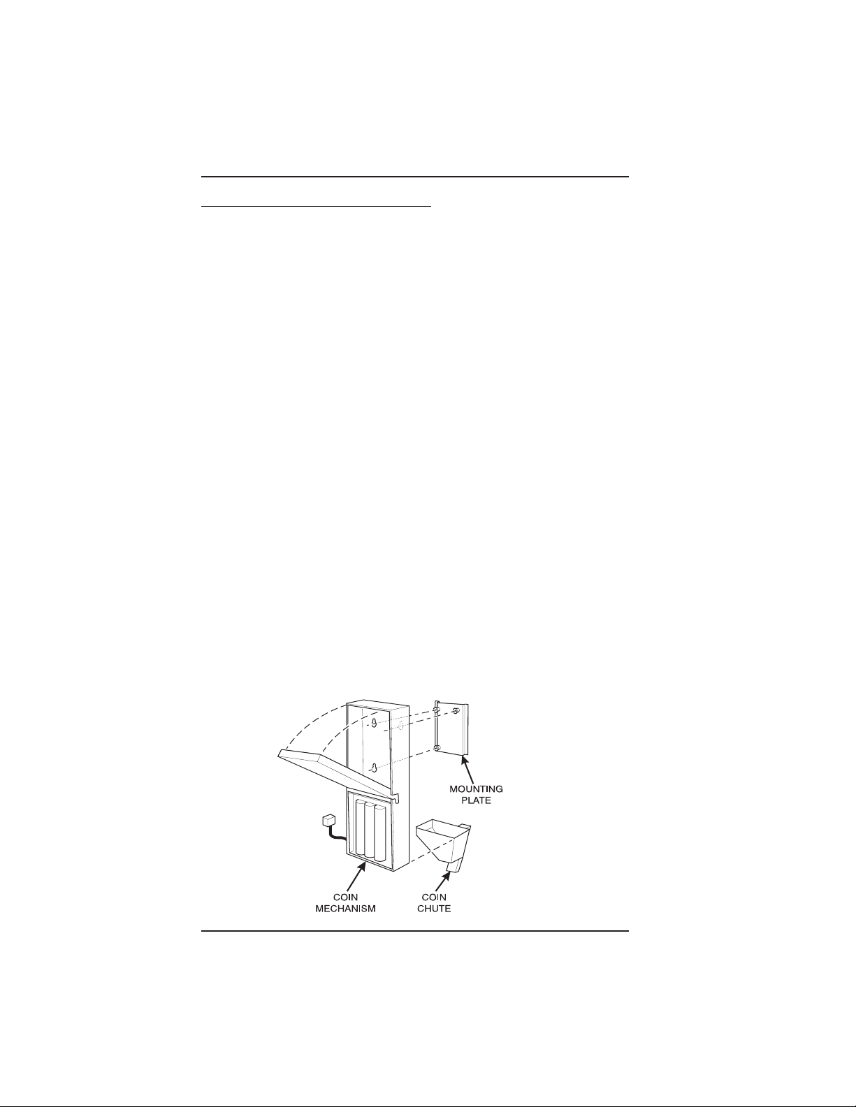
MDB Coin Mechanism
Install the coin mechanism as follows:
Make sure the main power switch is turned OFF before you
work on the merchandiser. Failure to do so could result in
death or injury.
a. Turn OFF the main power switch. Refer to the instructions provided with the coin
mechanism and remove the coin validator assembly.
b. Loosen the coin mechanism mounting screws on the merchandiser so they stand
off about 1/8" (0.3 cm).
c. Position the coin mechanism so the three keyed holes fit over the mounting screws.
Pull down on the coin mechanism to seat the screws in the keyways.
d. Tighten the mounting screws and reinstall the coin validator assembly.
WARNING
November, 2002 Page - 12 6700001
Page 31

HOT DRINK SETUP/PROGRAMMING GUIDE
e. The following figure shows a coin mechanism, bill validator, and card reader
connected to one another via an MDB. Some monetary configurations may not
include all of these devices. Connect your coin mechanism as shown:
f. Turn ON the main power switch. Select MDB MECH in the SELECT COIN
MECHANISM AND OPTIONS procedure on page 2-11. Press until the
standby message is displayed, then press . Insert enough coins through
the coin slot into the coin tubes to more than cover the empty sensor. Insert coins
one at a time and ensure they lay flat in the tubes. The amount of coins you insert
is internally recorded.
g. Payout about 6 coins to ensure proper loading.
h. Finish inserting coins through the coin slot to fill all the tubes with coins.
i. Visually check the coin tubes to make sure coins are not shingled.
6700001 Page - 13 November, 2002
Page 32

HOT DRINK SETUP/PROGRAMMING GUIDE
C
C
7. Fill the Tank:
a. Make sure the main power switch is ON.
b. Turn on the water at its source.
c. On the maintenance keypad, press
shows TANK.FILL.
d. Press . You should hear water running into the tank, and the display will
FILLING. The water will run until either the tank is full or 12 minutes go by,
show
whichever happens first.
The inlet water valve only stays open for 12 minutes at a time.
This is a safety feature to prevent water from running into a
leaky system and making a mess. It is possible for your tank
to take longer than 12 minutes to fill if your location has low
water pressure. To be on the safe side, check for leaks if the
water runs a long time. If you find none, everything is normal;
you just have low water pressure.
e. When you hear the water stop running, repeat steps 3 and 4. Under normal
circumstances, nothing will happen. If water starts running and the display shows
NOTE
, then press until the display
FILLING again, your pressure is low and it is just taking a long time to fill the tank.
Repeat this step if necessary to be sure your water tank is full.
8. Fill the Canisters:
Open the lid as shown, and carefully pour the appropriate product into the canister.
Repeat for all canisters in the machine.
FILL
CANISTER
ANISTER
AP
November, 2002 Page - 14 6700001
Page 33

9. Load Cups:
HOT DRINK SETUP/PROGRAMMING GUIDE
Use only cups which have been designed for use in a hot
beverage vending machine.
a. Support the cup mechanism in the upright position.
b. Push the latch forward to release the cup mechanism. Continue to support the
cup mechanism while you lower it into the loading position.
c. Remove the turret cover.
OBSERVE PROPER HYGIENE - DO NOT TOUCH THE CUPS!
d. Open the bottom of the wrapper on a stack of cups.
e. Insert the wrapped cups into the turret and pull the wrapper out.
DO NOT FILL CUPS ABOVE THE LEVEL MARKED ON THE
OUTSIDE OF THE CUP TURRETS OR ABOVE THE “FILL LINE”
LABEL INSIDE EACH TURRET, OR MOTOR JAMS WILL OCCUR. USE ONLY THE SAME SIZE AND BRAND OF HOT DRINK
CUPS IN EACH TURRET; DO NOT INTERMIX!
f. Replace the turret cover afrter theturrets have benn loaded.
g. Be sure the cup mechanism is locked into the upright position.
CAUTION
6700001 Page - 15 November, 2002
Page 34

HOT DRINK SETUP/PROGRAMMING GUIDE
10. Cup Size(s):
a. Make sure the cup sizes you select agree with the cups you have actually
loaded during setup.
b. Press , the display shows X. Y. OZ. “X” is the currently selected drink
size for the cups in turret 2 (normally large cups), “Y” is the currently selected drink
size for the cups in turret 1. (Normally regular cups).
c. Press
cup ring size.
d. Any changes made to the cup sizes must be “locked in”. There are two ways to
do this:
1) If you are keeping some cup sizes the same, or putting the cups in different cup
rings, press and hold
sound, then shows FINISHED. This will reassign the old throw times to the new cup ring,
if possible.
2) If you are loading all different size cups, or want to load all new default times, press
and hold . The display momentarily shows CLEARING, two beeps sound, then
shows FINISHED. This will reload the factory default times you have established. (See
the tables on the following pages for the factory default times).
e. CONTINUE
to change the #1 cup ring size; press to change the #2
. The display momentarily shows CLEARING, two beeps
November, 2002 Page - 16 6700001
Page 35

HOT DRINK SETUP/PROGRAMMING GUIDE
11. Test the Machine:
Your Hot Drink merchandiser is now ready to vend coffee, just as soon as the water
in the tank reaches its operating temperature. Press , and a reading of the
tank temperature is displayed. When the display shows 94° C (202° F), it is ready
for vending.
a. Close the door, make a selection, and enjoy your cup of coffee!
b. You will now need to do the following before your machine is ready to start earning
money:
• Set prices
• Set up the menu
• Establish time of day vending periods (if desired)
• Customize the drink recipes (if desired)
• Set up custom messages (if desired)
Refer to the Programming section for details on these and other procedures.
12. PosiVend:™
PosiVend™ensures that a cup is always available in the cup station before any money
is collected or product delivered. The sensing system is a beam of infra-red light
across the cup station which is broken by the cup when it falls into posi-tion.
The PosiVend™ software monitors the cup station sensor during the time
the cup ring is cycled and for three seconds afterward. If a cup is not
detected, the soft-ware will first determine if a second cup ring with the
same size cups exists and will then try to drop a cup from the second ring.
If the second ring also fails to drop a cup or is not usable, the software will
repeat the attempt from the first cup ring to attempt to clear any jams in the
cup delivery area. Each ring will be tried up to two times. If a cup is still not
detected by the infrared sensor then several things happen:
• Any ring that failed twice in a row is placed temporarily out-of-service for a length
of time that is determined by the user,
• The customer’s credit is either restored for another vend attempt or is returned
automatically,
• Three beeps are sounded and the message SELECT ANOTHER SIZE is flashed if
another size cup ring is available, or the message INSERT MUG is flashed in the event
that no other cups are available. The customer may always get his money back by
pressing the coin return button.
INSERT MUG is the default message.
You may customize this message if desired.
6700001 Page - 17 November, 2002
Page 36

HOT DRINK SETUP/PROGRAMMING GUIDE
Special rules exist to protect both the customer and the operator from loss.
First and foremost, the customer is protected because no drink is spoiled
nor money lost because a cup fails to fall to the cup station. The customer
is given every chance to get his original choice of cup size by trying at least
twice per ring to eject a cup. If two rings are available with the same cup
size, the system will alternately try to vend a cup from each ring until the
cup is delivered or both rings are placed out-of-service.
The operator is protected by the anti-jackpot program of the system. It is
con-ceivable that a customer could prevent cups from reaching the sensing
area of the cup station in order to steal the cups and then get his or her
money back for the vend. Under the PosiVend™ Anti-Jackpot system, the
operator can lose no more than two cups in a row per ring. Then that ring is
temporarily placed out-of-ser-vice both to protect the customer and to
discourage theft. The amount of time that the cup ring is out-of-service is
programmable from 0 to 99 minutes. After the time has elapsed, the cup ring
will return to service but the count of the two failures is kept. If the
previous problem was theft, then the next vend attempt from that ring will
be successful and the count of the two previous failures will be erased. If
the problem is an actual system failure, then the third failure will
permanently place that cup ring out of service until a service technician
visits the machine.
Alternate cup vends and mug vends still work as before. If a cup ring is out
of service due to PosiVend™ the alternate vend will only be from a selected
large cup to a small cup at the small cup price. An induced PosiVend™
failure cannot cause an alternate vend from a selected small cup to a large
cup at the small cup price. This protects the operator from customers trying
to get large cup drinks at a small cup price. (PosiVend™ will not
automatically switch to a different cup size in mid-vend because it cannot
be ensured that correct change will be returned for the new price.)
PosiVend™ can be turned off if desired, (See TURN POSIVEND™ ON OR
OFF page 49).
November, 2002 Page - 18 6700001
Page 37

HOT DRINK SETUP/PROGRAMMING GUIDE
R
WATER
V. ADJUSTMENTS AND MINOR
MAINTENANCE
1. Empty the Bill Stacker
2. Adjust the Water Valves
Water valves do not usually require adjustment, but in some cases adequate water
volume cannot be achieved by the throw time setting alone (see the programming
section). IF ABSOLUTELY NECESSARY, adjust the valves in conjunction with setting
the factory default timers during the Product Configuration programming mode.
1. Using a slotted screwdriver, turn the adjustment screw clockwise to decrease
the water flow rate.
2. Turn the adjustment screw counterclockwise to increase the water flow rate.
WATER
TANK
123456
WATER VALVE
ADJUSTMENT
6700001 Page - 19 November, 2002
SCREW
6
+
-
WATE
VALVE
Page 38

HOT DRINK SETUP/PROGRAMMING GUIDE
FILL
CANISTER
CANISTER
SHELF
PINS ON MOTOR
SHAFT MUST ENGAGE
SLOTS
IN CANISTER
COUPLER
Y
3. Adjust the Air Pressure.
This control determines the system pressure provided
by the air compressor. Adjust as follows:
a. With the compressor running, pinch the brewer inlet
air tube.
b. Adjust the pressure to read 10 - 12 psi on the
gauge.
This will produce a pressure of 3 - 6 psi using regular
coffee and 8¼ oz cups. No further air
pressure adjustments should be
necessary.
PRESSURE
ADJUST
CONTROL
4. Install Canisters.
1. Place the canister in position as shown.
2. Engage the pins on the motor shaft with the slots in the canister coupler.
3. Fit tabs on canister into the slots on the canister shelf.
4. To ensure canister is correctly engaged with the rear mounting bracket, gently
push down on the front edge of the canister lid.
PRESSURE
GAUGE
INCREASE
INGREDIENTS SHELF
MONETAR
PANEL
PINS ON MOTOR
SHAFT MUST ENGAGE
SLOTS IN CANISTER
FILL
CANISTER
CANISTER
SHELF
November, 2002 Page - 20 6700001
COUPLER
626P0017
Page 39

HOT DRINK SETUP/PROGRAMMING GUIDE
5. Adjust the Cup Mechanism.
1. Place seven cups in the cup ring.
2. Observe the clearance as shown in view B.
3. If necessary adjust by first loosening the adjustment arm screw (view A).
4. Move adjustment arm until correct clearance is achieved.
5. Hold adjustment arm in place and tighten adjustment arm screw.
ADJUSTMENT
ARM
VIEW A
LOOSEN SCREW
MOVE ARM
CUP
CAM
CUP
CAM
VIEW B
This clearance is just
large enough to allow
cup ejection
6700001 Page - 21 November, 2002
CORRECT
ADJUSTMENT
ADJUSTED
TOO TIGHT
ADJUSTED
TOO LOOSE
This side is snug
against cam
316P0118
Page 40

HOT DRINK SETUP/PROGRAMMING GUIDE
N
S
6. Set Up the Menu Assembly.
1. From the inside of the door, remove the two screws as indicated, and remove the
end cap as shown.
2. Loosen the remaining 10 screws as indicated 1/2 turn. Do not loosen the screws
any more than necessary to avoid stripping out the menu frame.
3. Remove the menu board. If it is still held too tightly, repeat step 2.
4. Set up the menu board as desired and reinstall it in the reverse order of
disassembly.
REMOVE THE MENU BOARD
END CAP AND SLIDE OUT THE
MENU BOARD.
LOOSEN
THESE
SCREWS
REMOVE
THESE
SCREWS
LOOSE
THESE
SCREW
November, 2002 Page - 22 6700001
Page 41

HOT DRINK SETUP/PROGRAMMING GUIDE
PROGRAMMING THE HOT DRINK
Getting Around
Getting around the Hot Drink software is pretty easy once you know the
features that are available to you, and how to use them. The three main
parts you will use are the SERVICE KEYPAD, the SELECTION SWITCH
PANEL, and the DISPLAY.
The Service Keypad
For most of your programming
jobs, you will be using the
service keypad conveniently
located on the monetary
panel. The service keypad
has 16 keys. The three
columns on the left are the
mode keys. The right hand
column contains the
movement keys.
PROGRAMMING THE HOT DRINK
The Selection Switch Panel
AB
DEF
G
H
C
J
The selection switch panel is also
located on the monetary panel. Unlike the service keypad, it is accessible when the cabinet door is closed.
These are the keys the customer will
use to make selections. You can also
use these keys during programming
procedures.
XYZ
636P0044
6700001 Page - 23 November, 2002
Page 42

HOT DRINK SETUP/PROGRAMMING GUIDE
The Displays
The 10-character display performs two functions, and is referred to in
this book as "the display":
1. It shows the customer's selection and how much credit is in the
machine, as well as the ready, service, and time of day messages.
2. It provides information and feedback to the service person during
maintenance.
DISPLAY
November, 2002 Page - 24 6700001
Page 43

HOT DRINK SETUP/PROGRAMMING GUIDE
The Function Keys
The FUNCTION keys on the service keypad can be used for up to three
things:
THE PRIMARY PUR-
POSE
THIS IS THE MAIN JOB OF
THE
KEY. FROM THE
THE NUMBER
YOU MIGHT BE ASKED TO
ENTER
A NUMERICAL VAL-
UE. YOU CAN DO THIS
IN
TWO WAYS: PRESSING
THIS
KEY IS THE SAME AS
PRESSING
THE "5" ON
STANDBY
PROGRAMMING
THE SECONDARY
PURPOSE THIS IS THE
KEY
'S "SECOND JOB". THIS
KEY
CAN BE USED TO DELETE
A
CHARACTER WHEN YOU
ARE
MESSAGE, IT WILL
ALLOW
YOU TO ENTER A
MODE. IN
EDITING CUSTOM MES-
Other Keys
The MOVEMENT keys on the control panel let you move inside a mode,
and back and forth between modes. To see how these keys let you
move around, study the flow diagram on the next page.
The up and down arrow keys are your "legs", which let
you move up and down the list of tasks. These keys are
what let you continue from one step to the next in
programming procedures.
This is your "activate" or "choose" key. It "opens a door" to
additional information and lets you begin a programming task
once you are inside of a mode. Sometimes, it is used as a
toggle switch to show you your choices during a programming
task.
This is your "end" key. Pressing it one or more times will move
you back to the start of the mode, or all the way back to the
standby message.
This key lets you start an action, such as a test.
6700001 Page - 25 November, 2002
Page 44

HOT DRINK SETUP/PROGRAMMING GUIDE
III. CONTROL PANEL SWITCHES EXPLAINED
Press this button to put your machine into the Price Setting
mode. You can see maximum and minimum machine
prices, and change prices for entire machine or individual
selection.
Press this button to set up how the Free Vend mode will
operate.
Press this button to view the water tank temperature,
software version number, machine and accessory configuration, and active selection status.
Press this button to:
• Select display language
• Select coin mechanism and
options
• Select bill validator and options
• Select card reader and
• Select monetary options
• Set winner feature
options
Press this button to:
• View total sales and vends
by whole machine, selection, or drink size
Press this button to:
• Download data into your portable data collection device
(PDCD), OR
• Set printer baud rate, depending upon which device you
are using
Press this button to:
• Set machine type configuration
• Set which selections are
active
November, 2002 Page - 26 6700001
• Clear resettable data
• View or set machine
• Set up blended selections
• Set up cup sizes
Page 45

HOT DRINK SETUP/PROGRAMMING GUIDE
Press this button to:
• Set time of day
• Set day, month, year
• Set up time of day intervals for
inhibit, freevend, and discount
vending
Press this button to pay one or more coins from the coin
mechanism.
• Allows you to see any fault or condition that has placed
the machine out of service
• Select display messages
• Edit messages
• Set message scrolling speed
Press this button to:
• Perform TEST VENDS
• Test machine functions
Press this button to:
• Enter the SUPERVISOR mode
• Change the SUPERVISOR access
code
• Test displays
• Fill the water tank
• Lock and unlock
access to functions
6700001 Page - 27 November, 2002
Page 46

HOT DRINK SETUP/PROGRAMMING GUIDE
Programming Procedures
SOME CONVENTIONS:
The pages that follow contain all the programming procedures for the Hot
Drink. If you need to do a specific task, you can find it immediately by
using the Programming Index. Most of the procedures have things in
common, and here is a short guide to help you through these conventional
presentations:
All programming procedures assume that you are starting with the
standby message showing in the display. If not, just press until
you get there.
Each programming procedure is highlighted by a pointing hand:
so it will stand out.
PROGRAMMING PROCEDURES
To exit a mode (CONTINUE) at any time, press . Sometimes
you may have to press the key more than once in order to exit all the
way to the standby message.
Text that looks like this: DISPLAY represents what you will see
in the display on the monetary panel.
Definitions and helpful information will appear in shadow boxes:
HELPFUL HINT
THE SUPERVISOR MODE
The supervisor is allowed to do things that a normal user cannot, like
controlling access to certain modes. The supervisor can lock out any
of the programming modes to anyone who does not have the right "key".
Once a supervisor enters the proper code, he or she will be able to:
• Change the supervisor access code
• Lock out any or all of the service keypad modes
• Select whether price lines are used
• Set whether data is cleared after being downloaded into a portable
data collection device
• Grant or deny access to data items during DATA RECALL
• Modify the machine configuration
November, 2002 Page - 28 6700001
Page 47

HOT DRINK SETUP/PROGRAMMING GUIDE
GAIN ACCESS TO THE SUPERVISOR MODE
1. Press . The display shows: ENTER CODE. You must
enter the four-digit supervisor code within 6 seconds to gain
access.
NOTE
A new machine has a factory-set supervisor code of
0000.
When you have entered the right code, you will hear two beeps
and see UNLOCKED in the display.
ENTER A NEW SUPERVISOR CODE
1. Follow the steps in GAIN ACCESS TO THE SUPERVISOR
MODE.
2. Press , then until the display shows SUPER XXXX.
The X's represent the current supervisor code. Use the number keys
to enter a new code.
IMPORTANT!
If you enter a new code, be sure to keep a written
record of it. There is no other way to access the
SUPERVISOR mode.
3. CONTINUE.
ENTER A FREEVEND CODE
1. Follow the steps in GAIN ACCESS TO THE SUPERVISOR
MODE.
2. Press until the display shows FREE XXXX.
THE SUPERVISOR MODE
The X'sreresent the current freevend code. Use the number keys to
enter a new code. If the code is anything other than "0000", it must
be entered after the key lock is turned in order to enable free vends.
3. CONTINUE
6700001 Page - 29 November, 2002
Page 48

HOT DRINK SETUP/PROGRAMMING GUIDE
LOCK OR UNLOCK MODE OR PAYOUT KEYS
1. Follow the steps in GAIN ACCESS TO THE SUPERVISOR
MODE.
2. Press until the display shows either X. LOCKED or
X. UNLOCKED. "X" refers to the number or character shown on the
mode or payout key in question (1 through 9, # and *). To see if a
key is locked or unlocked, press that key.
3. Press to change between locked and unlocked. When
anyone other than the supervisor tries to enter a locked mode, the
display shows LOCKED.
NOTE
The following mode keys cannot be locked out:
4. CONTINUE.
SET PRINTER OR DEX OPTIONS
1. Follow the steps in GAIN ACCESS TO THE SUPERVISOR
MODE.
2. Press until the display shows:
PRINTER means that data will be sent directly to a printer,
OR
DEX ONLY means that data remains in memory after it is down-
loaded into a portable data collection device (PDCD),
OR
DEX +CLR means that resettable data is cleared after it is down
loaded into a PDCD.
3. Press to change between the three choices.
4. CONTINUE.
November, 2002 Page - 30 6700001
Page 49

HOT DRINK SETUP/PROGRAMMING GUIDE
LOCK OR UNLOCK DATA CLEARING ACCESS
1. Follow the steps in GAIN ACCESS TO THE SUPERVISOR
MODE.
2. Press until the display shows either #. LOCKED or
#. UNLOCKED. LOCKED means that non-supervisors cannot clear
resettable machine sales and vend data from the key.
3. Press to switch between #. LOCKED and #. UNLOCKED.
NOTE
The supervisor can clear data regardless of this
setting, provided the supervisor code was correctly
entered first.
4. CONTINUE
SELECT DISPLAY LANGUAGE
1. Press . The current LANGUAGE is shown in the display.
Press to choose the desired language. Your choices are:
ENGLISH, DEUTSCH, FRANCAIS, ESPANOL, PORTUGUESE,
SWEDISH, or
NEDERLANDS.
2. CONTINUE
6700001 Page - 31 November, 2002
Page 50

HOT DRINK SETUP/PROGRAMMING GUIDE
SELECT COIN MECHANISM AND OPTIONS
1. Press , then press until the current COIN
MECHANISM is shown in the display. Press to choose the
desired coin mechanism. Your choices are: DUMB MECH,
MDB MECH, EXEC MECH, or NO MECH
NOTE
If you selected EXEC MECH you can exit the function.
2. Press until the display shows CHANGE X.XX.
Coins and bills which are less than or equal to this value will be
returned without a purchase being made.
Examples:
CHANGE 0.00 - Forced vend; NO change returned without a
purchase.
CHANGE .25 - Nickels, dimes, and quarters returned with-
out purchase.
CHANGE 1.00 - $1 bills and SBAs will be returned as
change without purchase. Nickels, dimes, and
quarters are also returned.
3. Press until the display shows: LOW.MSG X.XX. The
display will show USE EXACT CHANGE when the amount of available change in the coin mechanism falls below the value of "X.XX".
Enter a value with the number keys. For example, if LOW.MSG
1.00 is displayed, the USE EXACT CHANGE message is dis-
played when less than a dollar's worth of change is in the coin
mechanism.
4. CONTINUE.
November, 2002 Page - 32 6700001
Page 51

HOT DRINK SETUP/PROGRAMMING GUIDE
SELECT BILL VALIDATOR AND OPTIONS
1. PRESS
IS DISPLAYED:
, THEN PRESS UNTIL ONE OF THE FOLLOWING
NO DBV - No bills will be accepted or there is no bill
validator installed (you can exit the function).
SER.1.2.5.10.20 -The serial bill validator is selected and will
accept $1, $2, $5, $10, and $20 bills. Use
BILL SELECTION METHOD below to change
the bills which will be accepted.
MDB.1.2.5.10.20 -A standard MDB bill validator is selected.
It will accept $1, $2, $5, $10 and $20 bills.
Use BILL SELECTION METHOD below to
change the bills which will be accepted.
BILL SELECTION METHOD:
The standard $1, $2, $5, $10 and $20 bills
are enabled by pressing the 1, 2, 5, 6, or 7
key(s), respectively, to display which bill(s)
will be accepted.
MDB. <*> - An MDB bill validator which accepts non-
standard bills or tokens is connected and
operating. Press to enter list of bills.
(See INITIAL SETUP OF NONSTANDARD
BILL VALIDATOR on the following page.)
BILL LIST OPERATION:
Use and to scroll through the
list of bills.
Use to turn the bill acceptance ON or
OFF.
Use to move up to the top level
screen.
6700001 Page - 33 November, 2002
Page 52

HOT DRINK SETUP/PROGRAMMING GUIDE
1. 1.00 ON -1. = Bill validator channel
1, each bill has its own channel
1.00 = Bill value
ON = $1.00 bill will be accepted
1. 1.00 OFF -OFF = $1.00 bill will not be
accepted
TKN - Token bills (same as coupon
bills)
INITIAL SETUP OF NONSTANDARD BILL VALIDATOR:
Connect the bill validator, select MDB in the
bill validator selection screens. The stan-
dard "MDB.1.2.5.10.20" screen will appear first. Exit the bill validator setup by
pressing . Bill information is now col-
lected from the validator. Re-enter the bill
validator selection screen and the nonstand-
ard screen "MDB. <
>" will appear.
*
PULSE DBV - The pulse bill validator will accept $1 bills.
Press to choose the desired option.
2. CONTINUE.
November, 2002 Page - 34 6700001
Page 53

HOT DRINK SETUP/PROGRAMMING GUIDE
SELECT MONETARY OPTIONS
This function lets you:
• Set declining balance,
• Set currency acceptance on low change,
• Set overbuy options,
• Set last bill stacking options
DECLINING
BALANCE:
1. Press , then press until one of the following is dis-
played:
Once credit is established, multiple vends
may occur until the coin return is pressed.
DECLINE.ON - More than one vend is allowed, with a declining
balance.
OR
DECLINE.OFF - A declining balance is not allowed.
Press to display the desired choice.
2. Press until one of the following is displayed:
ACC <$$ X.XX - The last bill which meets or exceeds maxi-
mum price will be held in escrow.
OR
ACC.STK X.XX - The last bill which meets or exceeds maxi-
mum price and MDB coupon bills (token bills) will
be immediately stacked.
Example: If setting is ACC.STK 1.00 and maximum price
is $1.50. This setting will immediately stack the
second $1.00 bill inserted.
6700001 Page - 35 November, 2002
Page 54

HOT DRINK SETUP/PROGRAMMING GUIDE
Press to display the desired choice.
The value of "X.XX" has two purposes:
a. The value of "X.XX" tells the machine how big a bill or coin
to accept even though there is not enough change in the coin
mech to cover all possible paybacks.
• For example, enter 1.00. Therefore, the machine will take a
dollar bill or coin even though there is less than $1.00's worth
of change. Entering 5.00 tells the machine to take a five even
though there is less than $5.00's worth of change, and so forth.
NOTE:
This could cause a customer to be shortchanged.
• Entering 0.00 means that bills or coins will only be accepted if
there is enough change to cover them.
b. The value of "X.XX" tells the machine how much the customer is allowed to overbuy a product. The customer will be
shortchanged when an overbuy occurs.
Example:
For a value of $0.25: if there is no change in the machine
and the customer inserts a $1.00 bill. The customer can purchase a product for $0.75 even though the change cannot be
paid back. The customer will be shortchanged. Normally a
purchase will not be approved unless all change can be paid.
Entering 0.00 means that the vend will only be approved
when the correct change can be returned (overbuy disabled).
(Continued)
November, 2002 Page - 36 6700001
Page 55

HOT DRINK SETUP/PROGRAMMING GUIDE
• For example, enter 1.00. Therefore, the machine will take a dol-
lar bill or coin even though there is less than $1.00's worth of
change. Entering 5.00 tells the machine to take a five even
though there is less than $5.00's worth of change, and so forth.
NOTE:
This could cause a customer to be shortchanged.
• Entering 0.00 means that bills or coins will only be accepted if
there is enough change to cover them.
b. The value of "X.XX" tells the machine how much the customer
is allowed to overbuy a product. The customer will be shortchanged when an overbuy occurs.
Example:
For a value of $0.25: if there is no change in the machine
and the customer inserts a $1.00 bill. The customer can purchase a product for $0.75 even though the change cannot be
paid back. The customer will be shortchanged. Normally a
purchase will not be approved unless all change can be paid.
Entering 0.00 means that the vend will only be approved
when the correct change can be returned (overbuy disabled).
3. CONTINUE
SELECT CARD READER AND OPTIONS
1. Press , then press until the current card reader is
shown in the display. Press to choose the desired card
reader. Your choices are: NO CARD, DUMB CARD, or
MDB CARD.
2. Press until one of the following is displayed:
REVALUE.ON - Allows credit to be transferred onto the card
REVALUE.OFF - Credit cannot be transferred to the card
Press to display the desired choice.
3. CONTINUE
6700001 Page - 37 November, 2002
Page 56

HOT DRINK SETUP/PROGRAMMING GUIDE
SET UP WINNER MODE
WINNER:At pre-selected intervals, a customer may re-
ceive a refund for a selection. You can select the
intervals and qualifying selections.
1. Press , then press until one of the following is dis
played:
WINNER OFF Winner function is disabled.
OR
WIN XXX Winners are allowed at certain intervals, represent
ed by "XXX".
Press to display the desired choice.
If you selected WINNER OFF, you can CONTINUE. Otherwise,
go to the next step.
2. The display shows WIN XXX. XXX represents the number of
vends which must occur per each winner vend. For example, an interval number of 50 means that a winner can happen any one time
during the next 50 vends. Using the number keys, enter an interval
number between 10 and 9999.
3. Press . The display shows
display represent which selections are allowed winners. Press the
appropriate letter key to enable a selection; pres the key again to
disable it. For example, pressing A, C, and E will cause the display
to look like this:
tions can have a winner.
ADVANCED OPTIONS:
• Press to enable all selections; press to disable all
selections.
• Press 0 or 1 to enable winners by cup size.
AN EXAMPLE . . .
You want to enable winners on all selections except E and F.
Do the following:
November, 2002 Page - 38 6700001
.A-C-E----, meaning that all A, C, and E selec-
*
.---------. The dashes in the
*
Page 57

HOT DRINK SETUP/PROGRAMMING GUIDE
a. Press
play instead of the dashes.
b. Press E and F. The letters
placed by dashes.
4. CONTINUE.
SET UP THE MUG DISCOUNT
1. Press , then press until the display shows MUG
. The letters A through J appear in the dis-
E and F in the display are re-
DSC XX. XX represents the value of the discount customers will re-
ceive for using their own mugs or cups. Enter the amount with the
number keys. Enter 0 for no discount.
2. CONTINUE.
SET THE PRINTER BAUD RATE
1. Press . The display will show one of the following rates:
BAUD 1200, BAUD 2400, BAUD 4800, or BAUD
9600.
2. Press until the desired baud rate is displayed.
NOTE:
This baud rate must match that of your printer, or it will not function
properly.
3. CONTINUE.
6700001 Page - 39 November, 2002
Page 58

HOT DRINK SETUP/PROGRAMMING GUIDE
LOCK OR UNLOCK SELECTIONS
1. Press
list of selections which are locked. Here, all selections are unlocked
because they show up as dashes (-). Press the appropriate selection letter to switch from locked to unlocked and back again. For example, to lock out the "A" and "C" selections, press those letter
keys on the selection switch panel. For this example, the display
will show LK. A - C - - - - .
You can lock all selections at once by pressing .
Unlock them all at once by pressing .
2. CONTINUE.
DISABLE SELECTIONS IN THE MERCHANDISER
. The display shows LK. - - - - - - - . This shows a
Selections can be LOCKED OUT (made unavailable for vending). You may want to do this if there
is a problem with that selection, such as no product in the canister.
1. Press , then press until the display shows something like this:
LK. ABCDEFGH. This display means that all regular size selections
(A - H) are not available for vending. An available selection has its
letter replaced by a blank space. Press to display the second
screen for X, Y, and Z selections.
2. Press the appropriate letter to toggle the display on or off.
NOTE
Press to lock all selections; press to
unlock all selections.
November, 2002 Page - 40 6700001
Page 59

HOT DRINK SETUP/PROGRAMMING GUIDE
ASSIGN CUP SIZES TO SELECTIONS
(SUPERVISOR MODE ONLY)
You can load up to two different sizes of cups in your machine (see set up cup sizes,
page ). You may not always want a certain selection to use all of the cup sizes in your
machine. For example, espresso is normally served in regular cups, so you probably
will not want it to be available in large or jumbo cups.
1. Press , then press , until the display shows something
like this: O. ABCDEFGH. This display means that the smaller of the two
cup sizes (0) is available for selections (A-H).
2. Press to display all selections; press to clear all
selections.
3. Press to display remaining selections (0 YZ2_ _ _ _ ). In
this display, the “Y and Z” represents the blended product, and the
“2” represents the cup only selection.
NOTE:
If you have only one cup size in your machine, you will
not see the next display.
4. Press . The display shows something like this:
1. ABCDEFGH. This display means that the larger of the two cup sizes
(1) is available for all selections (A - H).
5. Press the appropriate letter to toggle the display on or off. A selection that doesn’t vend the displayed size cup has its letter replaced by a dash (-).
6. Press to display all selections; press to clear all
selections.
7. Press to display remaining selections (1 YZ2_ _ _ _ ).
In this display, the “Y and Z” represents the blended product,
and the “2” represents the cup only selection. (Continued)
6700001 Page - 41 November, 2002
Page 60

HOT DRINK SETUP/PROGRAMMING GUIDE
To vend a cup only, press 1, 2, 3 (large size) or 2, 3 (regular size).
8. Continue
SET UP A HOT DRINK
Be sure that the cup sizes you set in (setup cup sizes page, ), agree with the
cup sizes actually in your machine. All procedures for setting up the hot
drinks are similar, so this example will demonstrate how to set up the A
selection, regular size fresh brew coffee.
1. Press
The star (*) represents the selection (A, B, etc.). The dash (-) represents
the size of the selection.
2. Press A. (If you were setting up the A selection for the large size drink,
you would press 1 first, then A.) The display shows WAT. A 12.00.
This means that the currently set water throw time for the A selection
is 12.00 seconds. Enter a new time if desired.
3. Press . The display shows DRY. A .60. This means that the
currently set dry product throw time for the A selection is .60 seconds.
Enter a new time if desired.
4. Pressing after each display will cause the following screens to
appear:
DRY. A+ View and change the settings for an extra strong drink
SUG. A View and change the settings for the sugar throw time
SUG. A+ View and change the settings for extra sugar throw time
LIT. A View and change the settings for the lightener throw time
LIT. A+ View and change the settings for extra lightener throw time
SUB. A View and change the settings for the sugar sub throw time
SUB. A+ View and change the settings for extra sugar sub throw time
STP. A View and change the steep time
STP. A+ View and change the steep time for an extra strong drink
AIR. A View and change the air compressor/pump running time
DLY. A View and change the amount of time after the vend to open
, then press until the display shows SETUP - *.
the auto vend door
November, 2002 Page - 42 6700001
Page 61

HOT DRINK SETUP/PROGRAMMING GUIDE
WHIPPER OPTIONS
WHP. A XXX Press to view and change the whipper settings as
follows:
ON- The last 3 seconds of the drink is always whipped
ON+ The whole drink is always whipped
OFF The drink is never whipped
OPT See below
• If J+ is selected (See SET THE MACHINE TYPE
CONFIGURATION CODE, PAGE 54 ):
OPT- The last 3 seconds of the drink is whipped only when the J
key is pressed
OPT+ The whole drink is whipped only when the J key is pressed
• If J- is selected (See SET THE MACHINE TYPE CONFIGURATION
CODE, PAGE 54):
OPT- The last 3 seconds of the drink is whipped unless the J key is
pressed
OPT+ The whole drink is whipped unless the J key is pressed
DIFFERENCES:
Some selections will not show all of these items. The E selection will have
some additional selections:
WA.2 E View and set the water throw time for the cappuccino second
product (chocolate)
DR.2 E View and set the chocolate throw time for cappuccino
PCT. E To automatically compute new times for cappuccino, enter a
percentage, then press . This percentage
represents the amount of chocolate product in
cappuccino, versus that in a normal chocolate drink.
This time and the normal coffee settings will compute
the new cappuccino time.
This is a handy way to move from one selection to another without
going to the SETUP screen first.
If you try to set up a selection that is not configured, the
SETUP screen will remain in the display.
6700001 Page - 43 November, 2002
Page 62
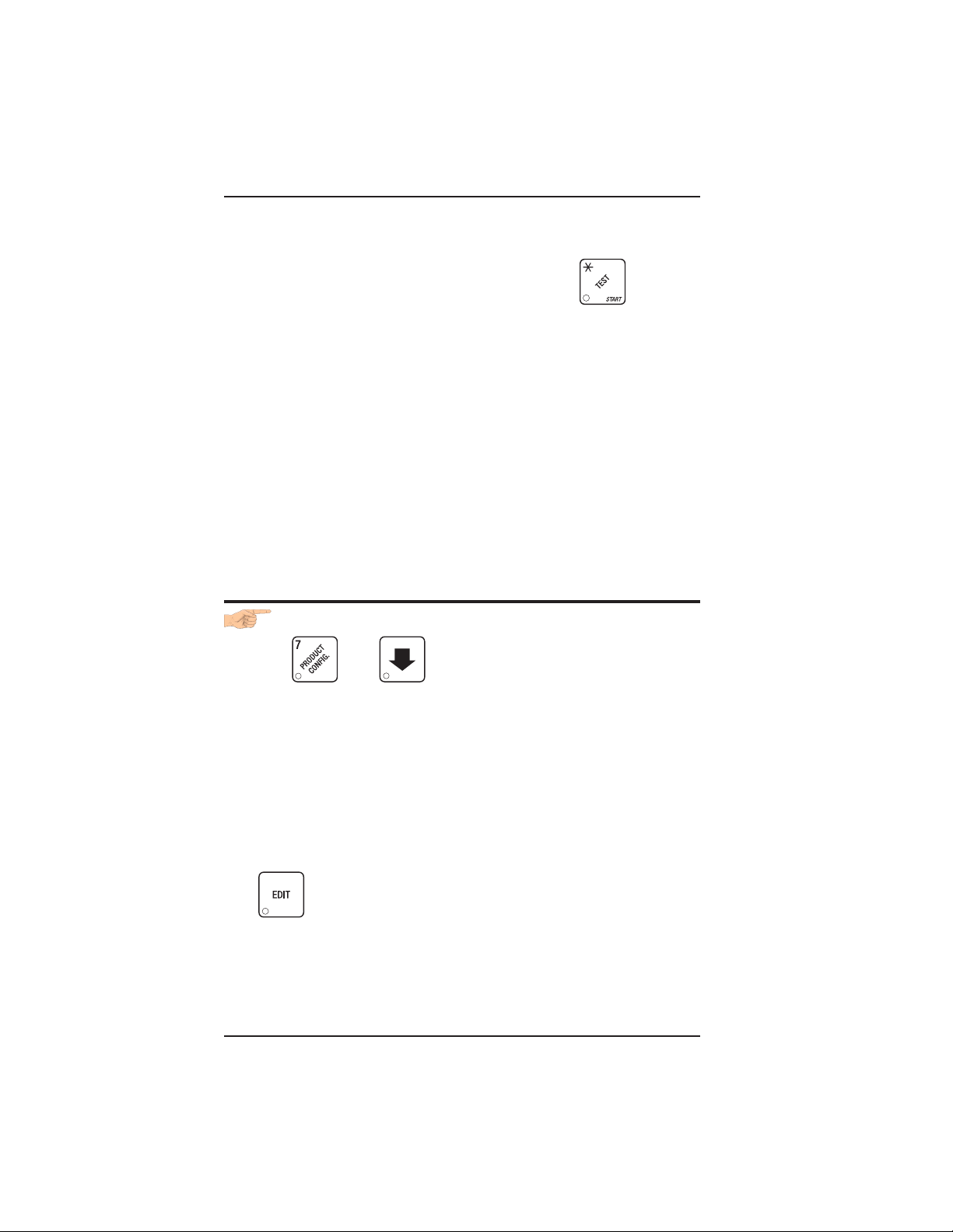
HOT DRINK SETUP/PROGRAMMING GUIDE
OPTIONS:
a. At any of the preceding displays, you can press to test
throw that item.
b. At any of the preceding displays, you can press * or # (on the selection switch panel) to step through a list of that item’s throw times
for other selections where that item is active. For example, pressing
# at the WAT. A display will show the throw time for WAT. B. This is
a handy way to move from one selection to another without going to
the SETUP screen first.
NOTE
If you try to set up a selection that is not configured, the
SETUP screen will remain in the display.
5. Continue.
VIEW OR SET THE HOT WATER TANK TEMPERATURE
1. Press then until the display shows SET 202 °F .
In this example, 202° is the water tank temperature setpoint in degrees Fahrenheit. If a decimal point appears next to the “F”, the
heater is on.
2 . If desired, enter a new setpoint in the accepted range of 149° - 205° F
(65° - 96° C).
NOTE
The lower limit for vending is 20° below setpoint, up to a
maximum of 180° F (82° C).
3. To change display units (replace the “F” with a “C” for Celsius), press
.
4. Continue.
November, 2002 Page - 44 6700001
Page 63

HOT DRINK SETUP/PROGRAMMING GUIDE
SET UP LOW TEMPERATURE DISPENSING
1. Press then press until the screen displays either
LTDIS OFF. This causes the machine to operate the same as the previ-
ous Hot Drink Center. For example, with a setpoint temperature of 202º F
the machine will inhibit vending when the water tank temperature reaches
182º F.
-or-
LTDIS ON. Allows vending to a water tank temperature of 140º F.
2. Press to change between ON and OFF.
3. Continue.
SET UP LOW POWER SETTINGS
Low power settings allow for the water tank to be set to a lower temperature
at up to 4 different dates and times. For example, you want to lower the tank
temperature to 160º F overnight on Mondays through Fridays. The machine
tank temperature setpoint will be changed to 160º F at 6:00 pm and maintained
at that temperature until 5:00 am on the following morning when the setpoint
is returned to 202º F. Please keep in mind that at 5:00, the machine will just
begin to increase to the 202º F setpoint temperature. It is up to you to
determine how long that will take and to allow enough time for the tank to be
at its proper temperature when the machine will be used. Typically, one hour
is adequate to return to the normal operating temperature.
NOTE:
The machine OUT OF SERVICE condition during the low power interval will
be determined by how you have set the LTDIS configuration.
(Continued)
6700001 Page - 45 November, 2002
Page 64

HOT DRINK SETUP/PROGRAMMING GUIDE
1. Press then press until the screen displays
LOW.PWR.
Press the number of the time interval you want to edit, or
time interval 1( we will use interval 1 for this example.
2. The display shows LOW.PW ON or LOW.PW OFF. This display tells
you whether your time interval (represented by 1) is on or off. Press
to change the condition of the time interval.
3 . If you turn an interval ON, it must be edited. You can edit a time
interval now, then turn it OFF until another time.
4. Press . The display shows 1.STRT X.XX.. X.XX is the
currently set start time. Enter a new start time (24-hour format) for this
interval. To enter the time for 6:00 pm, enter 1800.
5. Press . The display shows 1.STOP X.XX.. X.XX is the
currently set stop time. Enter a new stop time (24-hour format) for this
interval. To enter the time for 5:00 am, enter 0500.
Press . The display shows 1.@ - - - - - - -. The dashes represent
to edit
the days that this time interval is active. Pressing number keys 1
through 7 switches the days on/off. For example, press “2”, “3”, “4”,
“5”, and “6”. The display now shows 1.@ - M T W T F -.
This interval is active on Monday through Friday.
November, 2002 Page - 46 6700001
Page 65

HOT DRINK SETUP/PROGRAMMING GUIDE
SET THE RATIO OF CHOCOLATE IN CAPPUCCINO
1. Press , then press until the display shows either:
RATIO XX "XX" is the percentage of chocolate contained in a
cappuccino drink or
RATIO OFF No ratio is selected.
2. Press
the value of RATIO XX, enter the numbers directly. This is a quick
way to set up your cappuccino drinks. See table D2 to see the actual throw times/amounts for certain preset ratios. You can set a ratio
close to your taste, turn ratio OFF, then alter the product throw.
Leaving this step with RATIO OFF displayed does not
alter any previous settings for E and I selections.
Leaving this step with a ratio set will alter those
settings. The ratio automatically selects the times for
water and dry product throw. The E and I selections no
longer appear in the displays for those steps. If you
desire greater control over your cappuccino drinks,
leave ratio OFF.
3. CONTINUE.
SET THE BREWER RINSE TIME INTERVAL
1. Press , then press until the display shows SAN.TIM
to switch between these two displays. To change
NOTE
X.X. "X.X" represents the time of day (in hours and tenths of hours)
the machine rinses the brewer. For example, SAN.TIM 4.5 means
that brewer rinse takes place at 4:30 am. Use the number keys to
enter a new time, if desired. Range: 0.0 - 23.9 in .1 hour (6 minutes)
increments.
2. Press . The display shows SAN.HRS X.X. "X.X" repre-
sents how soon the machine rinses the brewer after the last brewed
selection. For example, SAN.HRS 2.5 means brewer rinse takes
place 2.5 hours after the last vend. Use the number keys to enter a
new time, if desired. Range: 2.0 - 12.5 hours, in .1 hour (6 minutes)
increments.
3. CONTINUE.
6700001 Page - 47 November, 2002
Page 66

HOT DRINK SETUP/PROGRAMMING GUIDE
SET THE BOWL RINSE TIME
Mixing bowl(s) can be automatically rinsed by one of two methods: You
can specify a set time of day when the bowl is rinsed, or you can specify
that rinsing takes place a set time after the last selection is vended.1.
Press then until the display shows one of the following:
RIN.HRS 2.5 - This is how soon the machine rinses the bowls after a
vend. In this example, bowl rinse takes place 2.5 hours after the last
vend. Range: 2.0 - 12.5 hours, in .1 hour (6 minute) increments.
-or-
RIN.TIM 4.5 - The time of day (in hours and tenths of hours) the machine
rinses the bowls. In this example, bowl rinse takes place at 4:30 am.
Range: 0.0 - 23.9 in .1 hour (6 minute) increments.
NOTE:
If 24 hours passes without a vend, no rinsing will take
place. This eliminates unnecessary rinsing over a
weekend or holiday.
-or-
RINSE OFF - No bowl rinse takes place.
2. Press to switch between these options, and the number keys
to enter new values.
3. Continue.
TURN POSIVEND™ ON OR OFF
1. Press then until the display shows one of the
following:
POSI.V OFF: None of the PosiVend™ functions are available. Use this if
the PosiVend™ system is not installed, or there is some reason you
do not want to use it (for example in a high cup theft situation).
POSI.V ON. The PosiVend™ system is operative. All of the PosiVend™
functions are available.
2. Press to switch between the two choices.
3. Continue.
November, 2002 Page - 48 6700001
Page 67

HOT DRINK SETUP/PROGRAMMING GUIDE
OPTIONAL OR MANDATORY POSIVEND™
1. Press then until the display shows one of the following:
OPT’N POSI.V: The machine reverts to home switch operation of the ring
motors if the PosiVend™ system cannot operate normally because of
an obstruction in the cup station or for any other reason.
MUST POSI.V: The vending machine is operational only if the PosiVend™
system is determined to be working. Otherwise, the machine will go
temporarily out of service until the blockage or other error is corrected.
2. Press to switch between the two choices.
3. Continue.
SET UP THE POSIVEND™ ANTI-JACKPOT TIMER
1. Press then until the display shows AJP.TMR XXM.
XX represents how many minutes PosiVend™ will be disabled for
either cup ring. The same value applies to the two timers
(one on each ring).
2. Enter a number using either keypad.
If any cup ring motor fails to deliver a cup on two consecutive attempts, the cup ring goes out of service. After the time set in step 2
has elapsed, the cup ring goes back in service and is given one
more chance to deliver a cup. If cup delivery is again unsuccessful,
the ring goes out of service until the machine is serviced. A successful delivery on any cup ring will reset the failed attempts for that
particular cup ring. If both cup rings perform three consecutive
failed attempts (and the PosiVend™ sensor is determined to be
working), the entire machine goes in the “mug only” mode until the
machine is serviced. If either cup ring performs three consecutive
failed attempts with the other cup ring in anti-jackpot timer mode,
the entire machine will be in “mug only” mode (assuming PosiVend
is working) until the preset time elapses (one more attempt will be
made to deliver a cup) or the machine is serviced by a route
operator.
6700001 Page - 49 November, 2002
Page 68

HOT DRINK SETUP/PROGRAMMING GUIDE
VIEW NUMBER OF MUG VENDS
(NOT SHOWN IF ZERO)
1. Press , then press until the display shows MUG
X. “X” is the number of mug vends.
2 . If desired, view this data by tray and individual selection.
3. Continue.
VIEW MACHINE ID NUMBER
1. Press , then press or until the display shows
I.D. XXXXXX . The X’s represent the 6-digit machine ID number.
2. You can edit the machine ID number if the supervisor access code has
been previously entered (See GAIN ACCESS TO THE SUPERVISOR
MODE).
3. Continue.
VIEW CUP RING CYCLES RELATED TO POSIVEND™
(NOT SHOWN IF ZERO)
1. Press , then press until the display shows PV.TOT
XX. XX represents the number of vends during which more than one
ring cycle was required to successfully dispense a cup.
2. Press to clear the count.
3. Continue.
November, 2002 Page - 50 6700001
Page 69

HOT DRINK SETUP/PROGRAMMING GUIDE
VIEW TIMES NO CUP WAS DETECTED AFTER A CUP
RING CYCLED
(NOT SHOWN IF ZERO)
1. Press , then press until the display shows PV.FL1
XX. XX represents the number of times a cup was not detected after
ring 1 cycled. Check the cup ring adjustment (see the Operator’s
Guide), or the cup stack for damage if the count is excessive.
2. Press to clear the count.
3. Press until the display shows PV.FL2 XX. XX represents the number
of times a cup was not detected after ring 2 cycled. Check the cup ring
adjustment (see the Operator’s Guide), or the cup stack for damage if
the count is excessive.
4. Continue.
VIEW HOME SWITCH USAGE RELATED TO POSIVEND™
(NOT SHOWN IF ZERO)
1. Press , then press until the display shows WO.PV XX.
XX represents the number of times home switches were used due to
OPT’N POSI.V selected but not working.
2. Continue.
6700001 Page - 51 November, 2002
Page 70

HOT DRINK SETUP/PROGRAMMING GUIDE
VIEW POSIVEND™ LAST RECORDED CALIBRATION
VALUE
1. Press PosiVend™ until the display shows CAL.LST XXX.
XXX can be any number from 0 to 255, and represents the most re-
cent value read from the sensor. The lower the number the greater
the sensor blockage. A number of 255 means that there is a fatal
problem with the PosiVend™ interface board. Ensure the PosiVend™ interface PCB is properly connected to the main controller
PCB.
2. Continue.
VIEW POSIVEND™ AVERAGE CALIBRATION VALUE
1. Press , then press until the display shows
CAL.AVE XXX. XXX represents the average sensor calibration
value (should be between 50 and 255 for proper sensor
operation - i.e. 51 through 254). Although this number could
go as low as 20, the PosiVend™ system will be inoperative in
this condition.
2. Continue.
CLEAR TANK ERRORS AND FILL THE TANK
1. Press , then press until the display shows TANK
FILL.
2. Press . This clears any tank error and starts filling the
tank, if necessary. If it is taking a long time to fill the tank AND
THERE ARE NO LEAKS, you may see TANK ERR in the diagnostic
list again. Just press again after making sure there are no
other problems, such as a restriction in the water inlet line or a
clogged water filter.
3. Continue.
November, 2002 Page - 52 6700001
Page 71

HOT DRINK SETUP/PROGRAMMING GUIDE
SET THE MACHINE TYPE CONFIGURATION CODE
(Supervisor Mode Only)
1. Press , then press until the display shows
Mach.type (x).
Press to enter MACH.TYPE (3).
2. Press . The display shows CONF WXYZ "WXYZ" is
the machine configuration code. W represents the machine type, X
is the soup and sugar substitute configuration, Y is the brewer configuration, and Z is canister mapping. The following tables give the
possible values for each of the four numbers. Enter the appropriate
configuration code for your machine.
3. CONTINUE.
noitarugifnoCepyTenihcaM
rofretnE
)W(
noitinifeD
1.esuetanretlarofdevreseR
noitarugifnoCetutitsbuSraguSdnapuoS
rofretnE
)X(
1.desutonsi5retsinaC
2.etutitsbusragussniatnoc5retsinaC
3.puossniatnoc5retsinaC
noitinifeD
6700001 Page - 53 November, 2002
Page 72

HOT DRINK SETUP/PROGRAMMING GUIDE
SINGLE BREW A machine with only one brewed selec-
tion (the second selection is freeze
dried). Uses a single barrel brewer.
DUAL BREW A machine with two brewed selections.
Uses a single barrel brewer.
noitarugifnoCrewerB
)Y(rofretnE
1)076ledoM(aetfaelroeeffoC-werBelgniS
2)076ledoM(eeffocfaceddnaeeffoC-werBlauD
3)876ledoM(rewerbon-ylnoyrDezeerF
noitinifeD
)woleBerugiFeeS(gnippaMretsinaC
rofretnE
)Z(
321
srebmuNretsinaCrofsretteLnoitceleSuneM
1F B A
2F A B
3B F A
eeffoC=A:xednIfaceD=BaeT=F
November, 2002 Page - 54 6700001
Page 73

HOT DRINK SETUP/PROGRAMMING GUIDE
CHOCOLATE
LIGHTENER
E
SOUP
6
OR
SUB
SUGAR
TEA
5
DECAF
3
COFFE
21
SET UP THE CUP ONLY OPTION (Supervisor mode only)
1. Press , then press until the display shows
CUPVND X/Y. This allows you to set whether a customer can buy
a cup only (no drink), and which types of cups will be vended.
"X/Y" represents the cup only vend configuration.
2. Press to switch between the following configurations:
-/- = Cup only not allowed
0/- = Regular cup only vended
-/1 = Large cup only vended
0/1= Both cup sizes vended
3. CONTINUE.
SET UP DELIVERY DOOR OPTIONS (Supervisor mode only)
1. Press , then press until the display shows either:
DOOR ON The automatic delivery door (if so equipped) is
enabled.
OR
DOOR OFF The automatic delivery door (if so equipped) is
disabled.
2. Press to switch between these two choices.
NOTE
DOOR OFF must be selected if your machine does
not have an automatic delivery door.
3. CONTINUE.
6700001 Page - 55 November, 2002
Page 74

HOT DRINK SETUP/PROGRAMMING GUIDE
S
S
COLLECTING DRY PRODUCT GRAM THROWS
Measuring the gram throw allows you to get the right amount of dry
product or condiment into your hot drink. To do this, you need a
container to catch the product throw and an accurate gram scale to
measure its weight.
1. Make a measuring container by cutting down a paper cup until it
fits under the canister spout as shown.
2. Weigh the measuring cup and zero the gram scale accordingly.
3. Make 5 test throws as instructed in the programming steps, then
average the results.
4. Weigh the test throw.
5. Repeat steps 3 and 4 until you get the correct product or condiment weight.
Tables D1 and D2 show the factory default settings for the various dry
products sold by the merchandiser. They are good starting points for
you to use in setting up your machine. In the end, the amount of dry
product or condiments you use in your drinks depends upon taste and
manufacturers’ recommendations. Recommended weights and times
are for guidance only, and you do not have to adhere to them.
UGAR
UBSTITUTE
LIGHTENER
SUGAR
COLLECTING DRY PRODUCT GRAM THROWS
CUP POSITION
FOR TEST
THROW
CHUTE
MIXING
COVER
COLLECTING CONDIMENT
THROWS
November, 2002 Page - 56 6700001
BOWL
FRESH BREW
COFFEE
CANISTER
CHUTE
CUP POSITION
FOR TEST THROW
COLLECTING INGREDIENT THROWS
Page 75

AeeffocwerbhserF
AeeffocyrdezeerF
AeeffocyrdezeerfgnortS
BfacedwerbhserF
BfacedyrdezeerF
BfacedyrdezeerfgnortS
D
D
D
E
E
E
FaettnatsnI
FaettnatsnignortS
GetalocohC
HpuoS
HtcudorPelbuloS
HOT DRINK SETUP/PROGRAMMING GUIDE
sgnitteStluafeDyrotcaFemiTworhTdnathgieWtcudorPyrD.1DelbaT
pucezisrep)smargni(thgieW
noitceleS
zo5zo7zo8zo9zo01zo21
07.5
00.8
06.1
09.0
53.0
01.1
56.0
07.5
06.1
09.0
53.0
01.1
56.0
eeffocwerbhserF
OSSERPSE
eeffocyrdezeerF
OSSERPSE
eeffocyrdezeerfgnortS
OSSERPSE
eeffocwerbhserF
ONICCUPPAC
eeffocyrdezeerF
ONICCUPPAC
eeffocyrdezeerfgnortS
ONICCUPPAC
07.5
06.1
09.0
53.0
01.1
56.0
07.5
06.1
09.0
53.0
01.1
56.0
09.0
07.0
01.1
09.0
00.71
08.2
03.4
07.0
0.01
54.2
00.9
02.2
05.2
02.1
05.1
05.0
06.0
05.1
08.1
09.0
01.1
00.8
00.9
02.2
05.2
02.1
05.1
05.0
06.0
05.1
08.1
09.0
01.1
00.8
00.9
02.2
05.2
02.1
05.1
05.0
06.0
05.1
08.1
09.0
01.1
00.8
00.9
02.2
05.2
02.1
05.1
05.0
06.0
05.1
08.1
09.0
01.1
02.1
05.1
00.1
52.1
05.1
08.1
52.1
06.1
00.42
00.4
56.4
00.6
00.7
00.1
51.1
5.31
2.61
53.3
00.4
00.01
08.2
06.1
56.0
00.2
02.1
00.01
08.2
06.1
56.0
00.2
02.1
00.01
08.2
06.1
56.0
00.2
02.1
00.01
08.2
06.1
56.0
00.2
02.1
06.1
03.1
00.2
57.1
00.82
00.13
51.5
06.7
52.1
8.71
53.4
___________________________________
pucezisrep)sdnocesni(semitworhT
00.11
01.3
08.1
07.0
02.2
53.1
01.3
08.1
07.0
02.2
53.1
01.3
08.1
07.0
02.2
53.1
01.3
08.1
07.0
02.2
53.1
08.1
06.1
02.2
58.1
56.5
05.8
53.1
7.91
58.4
00.31
56.3
02.2
09.0
06.2
06.1
00.11
00.31
56.3
02.2
09.0
06.2
06.1
00.11
00.31
56.3
02.2
09.0
06.2
06.1
00.11
00.31
56.3
02.2
09.0
06.2
06.1
02.2
58.1
06.2
01.2
00.43
00.14
08.6
02.01
56.1
7.32
08.5
6700001 Page - 57 November, 2002
DRY PRODUCT WEIGHT AND THROW TIME FACTORY DEFAULT SETTINGS
Page 76

HOT DRINK SETUP/PROGRAMMING GUIDE
,
)deunitnoC(
noitceleS
zo5zo7zo8zo9zo01zo21
01.3
IoniccuppacnidesuetalocohC
DosserpsenidesuraguS
DosserpsenidesuragusartxE
EoniccuppacnidesuraguS
EoniccuppacnidesuragusartxE
FaetnidesuraguS
FaetnidesuragusartxE
FaetnidesurenethgiL
FaetnidesurenethgilartxE
FaetnidesuetutitsbusraguS
FaetnidesuetutitsbusragusartxE
-*
*
-*
*
-*
*
-*
*
-*
*
-*
*
D
E
raguS
ragusartxE
renethgiL
renethgilartxE
etutitsbusraguS
etutitsbusragusartxE
osserpsE=
oniccuppaC=
05.4
55.0
57.0
01.2
00.3
53.0
54.0
00.3
53.4
05.0
56.0
05.3
01.5
54.0
56.0
06.4
08.6
06.0
09.0
02.4
00.6
55.0
57.0
05.5
00.8
07.0
00.1
02.1
05.1
07.0
58.0
05.1
00.2
58.0
51.1
06.0
58.0
57.0
50.1
08.0
01.1
00.1
53.1
02.4
00.6
55.0
57.0
05.5
00.8
07.0
00.1
02.1
05.1
07.0
58.0
05.1
00.2
58.0
51.1
06.0
58.0
57.0
50.1
08.0
01.1
00.1
53.1
sgnitteStluafeDyrotcaFemiTworhTdnathgieWtcudorPyrD.1DelbaT
*pucezisrep)smargni(thgieW
_________________________________
pucezisrep)sdnocesni(semitworhT
00.5
08.5
02.6
58.0
00.1
05.3
00.4
55.0
06.0
08.4
53.5
57.0
08.0
00.6
08.6
57.0
58.0
07.7
05.8
00.1
01.1
00.7
00.8
09.0
00.1
00.9
51.1
00.2
51.1
05.2
54.1
00.1
52.1
03.1
06.1
00.7
09.0
00.9
51.1
00.2
51.1
05.2
54.1
00.1
52.1
03.1
06.1
00.01
52.1
05.2
54.1
00.3
07.1
01.1
53.1
04.1
57.1
00.8
00.1
00.01
52.1
05.2
54.1
00.3
07.1
01.1
53.1
04.1
57.1
06.7
50.1
03.1
05.4
05.5
56.0
08.0
52.6
02.7
09.0
50.1
07.7
04.9
59.0
02.1
04.9
02.1
00.9
51.1
04.1
00.3
07.1
05.3
00.2
03.1
06.1
06.1
00.2
00.9
51.1
04.1
00.3
07.1
05.3
00.2
03.1
06.1
06.1
00.2
00.11
54.1
00.11
04.1
00.11
00.31
56.1
00.4
52.2
05.4
06.2
05.1
09.1
09.1
04.2
00.11
04.1
00.11
00.31
56.1
00.4
52.2
05.4
06.2
05.1
09.1
09.1
04.2
oniccuppacrofsemitetalocohC=I
*
epytehtnopugnidnepedyravlliwworhttnemidnocrotcudorpafothgiewmarglautcaehT
yrotcafnopudesabetamixorppaeranevigsthgiewehT.desutnemidnocrotcudorpfo
.gnitset
-*
*
.Fdna
E,D,C/B/Asnoitcelesrofelbaliavaerasremitetutitsbusragusdna,renethgil,ragusetarapeS
November, 2002 Page - 58 6700001
Page 77

HOT DRINK SETUP/PROGRAMMING GUIDE
CAPPUCCINO
Cappuccino is made with various ratios of chocolate to coffee, according to taste. Lightener (E timer) is also used for cappuccino. Table D2
shows numerous different ways to make cappuccino for each size of
cup in your machine. For example, the default chocolate-to-coffee ratio
of 15 - 85 in a 7 oz. cup consists of the following:
• A chocolate throw (product I) lasting 0.55 seconds, providing 15%
of the normal chocolate throw (approximately 4.5 grams*).
• A water throw for the chocolate (water I) lasting 2.55 seconds
(chocolate product throw plus 2 seconds to ensure the mixing
bowl is fully rinsed). The volume is about 56 ml, depending upon
how the flow rate is adjusted.
• A throw for cappuccino coffee (product E) equal to a normal coffee
(product A) throw.
• A water throw for the freeze dry coffee selection (water E) lasting
for 4.35 seconds (101 ml).
OR
CAPPUCCINO RECIPE
• A water throw for the fresh brew coffee selection (water E) lasting
for 4.00 seconds (115 ml). In either case the water volume is
enough to fill the remainder of the cup.
The actual mixing sequence is as follows:
1. The coffee portion of cappuccino is made using the same canister/
valve combination as the normal (A) coffee.
2. After the coffee is completely in the cup, the chocolate portion is
made with the selection G canister/valve combination. This gives
the drink its traditional "layering".
* Chocolate weights will vary with different products.
6700001 Page - 59 November, 2002
Page 78

HOT DRINK SETUP/PROGRAMMING GUIDE
FRESH BREW
CANISTERS
200 RPM
200 RPM, SOUP
60 RPM, SUGAR SUB.
200 RPM
200 RPM
60 RPM
200 RPM
SUGAR
LIGHTENER
TEA
DECAF
COFFEE
OR
SUB
SOUP
CHOCOLATE
65 32 1
MOTOR SPEED BY LOCATION
HINTS:
To “fine tune” your Cappuccino drink to your exact taste, set a ratio
close to what you like (between 15% and 50%), then turn ratio OFF.
Adjust the individual timers until you are satisfied. You may find it
necessary to cut down on the amount of sweetener available to a
cappuccino drink with a high ratio of chocolate, as the chocolate
contains sweetener of its own.
November, 2002 Page - 60 6700001
Page 79

HOT DRINK SETUP/PROGRAMMING GUIDE
sgnitteSretaW
tnecreP
)puc.zo5(oniccuppaCrofsgnitteStcudorPyrD.2DelbaT
sgnitteSretaW
tnecreP
)ces(gnimiT)lm(emuloV )ces(gnimiT)lm(emuloV )ces(gnimiT
sgnitteSretaW
sgnitteSretaW
tnecreP
)puc.zo7(oniccuppaCrofsgnitteStcudorPyrD.2DelbaT
sgnitteSretaW
tnecreP
)ces(gnimiT)lm(emuloV )ces(gnimiT)lm(emuloV )ces(gnimiT
sgnitteSretaW
)lm(emuloV
ETALOCOHC EEFFOCYRDEZEERFEEFFOCWERBHSERF
gnimiT
)ces(
04.025 05.2)tluafed(5875 05.2)tluafed(5885 52.2
55.045 06.20845 53.20855 51.2
56.065 07.25725 52.25735 50.2
57.095 58.20794 01.20794 09.1
thgieW
)mg(
)tluafed(5101.3
tnecreP
5200.5
0201.4
0308.5
50.166 02.35514 07.15514 55.1
58.016 59.25674 00.25674 08.1
5307.6
51.186 03.30583 06.10583 54.1
59.036 50.30644 58.10654 07.1
0503.9
0406.7
5404.8
ETALOCOHC EEFFOCYRDEZEERFEEFFOCWERBHSERF
)lm(emuloV
gnimiT
)ces(
55.065 55.2)tluafed(58101 53.4)tluafed(58511 00.4
07.095 07.20879 02.408011 58.4
58.036 09.25729 00.457401 56.3
thgieW
)mg(
)tluafed(5105.4
tnecreP
0208.5
5201.7
52.127 53.30618 55.30629 52.3
04.167 55.35577 53.35578 50.3
01.196 02.35668 57.35669 04.3
59.056 00.30709 09.307201 06.3
0300.8
5303.9
0405.01
5408.11
6700001 Page - 61 November, 2002
55.197 07.30527 51.30538 09.2
0501.31
Page 80

HOT DRINK SETUP/PROGRAMMING GUIDE
sgnitteSretaW
tnecreP
)puc.zo8(oniccuppaCrofsgnitteStcudorPyrD.2DelbaT
sgnitteSretaW
tnecreP
)ces(gnimiT)lm(emuloV )ces(gnimiT)lm(emuloV )ces(gnimiT
sgnitteSretaW
sgnitteSretaW
tnecreP
)puc.zo9(oniccuppaCrofsgnitteStcudorPyrD.2DelbaT
sgnitteSretaW
tnecreP
)ces(gnimiT)lm(emuloV )ces(gnimiT)lm(emuloV )ces(gnimiT
sgnitteSretaW
)lm(emuloV
ETALOCOHC EEFFOCYRDEZEERFEEFFOCWERBHSERF
gnimiT
)ces(
56.095 56.2)tluafed(58231 55.5)tluafed(58351 50.5
08.026 08.208821 04.508051 59.4
thgieW
)mg(
)tluafed(5104.5
tnecreP
0208.6
03.137 53.356211 57.456131 03.4
05.187 06.306801 06.406421 50.4
56.128 08.355501 54.455811 58.3
01.196 51.307711 59.407731 05.4
59.066 00.357221 51.557441 57.4
5200.8
0303.9
5300.11
58.158 59.30519 58.305211 56.3
0556.51
0407.21
5400.41
ETALOCOHC EEFFOCYRDEZEERFEEFFOCWERBHSERF
)lm(emuloV
gnimiT
)ces(
00.146 59.208431 56.508551 50.5
53.127 53.307521 03.507441 07.4
06.177 06.356911 50.556831 05.4
51.186 51.357031 05.557251 59.4
57.006 57.2)tluafed(58041 09.5)tluafed(58271 06.5
thgieW
)mg(
)tluafed(518.5
tnecreP
026.7
528.8
08.128 58.306311 08.406331 53.4
00.258 00.455901 56.455621 01.4
52.209 52.405501 05.405421 50.4
035.01
533.21
051.71
049.31
543.51
November, 2002 Page - 62 6700001
Page 81

HOT DRINK SETUP/PROGRAMMING GUIDE
sgnitteSretaW
tnecreP
)puc.zo01(oniccuppaCrofsgnitteStcudorPyrD.2DelbaT
sgnitteSretaW
tnecreP
)ces(gnimiT)lm(emuloV )ces(gnimiT)lm(emuloV )ces(gnimiT
sgnitteSretaW
sgnitteSretaW
tnecreP
)puc.zo21(oniccuppaCrofsgnitteStcudorPyrD.2DelbaT
sgnitteSretaW
tnecreP
)ces(gnimiT)lm(emuloV )ces(gnimiT)lm(emuloV )ces(gnimiT
sgnitteSretaW
)lm(emuloV
ETALOCOHC EEFFOCYRDEZEERFEEFFOCWERBHSERF
gnimiT
)ces(
50.156 59.208161 08.608871 51.6
03.107 02.357551 55.657271 59.5
05.147 04.307051 53.607761 08.5
08.006 08.2)tluafed(58661 00.7)tluafed(58581 04.6
thgieW
)mg(
)tluafed(512.6
tnecreP
08.108 07.356341 50.656951 05.5
50.258 59.306731 08.506251 52.5
03.209 02.455131 55.555441 59.4
05.249 04.405621 53.505831 57.4
020.8
528.9
033.11
536.31
057.81
043.51
541.71
)lm(emuloV
ETALOCOHC EEFFOCYRDEZEERFEEFFOCWERBHSERF
gnimiT
)ces(
00.146 00.3)tluafed(58322 53.9)tluafed(58132 51.8
03.107 03.308512 00.908322 58.7
55.167 06.357802 07.857512 55.7
58.128 09.307102 04.807702 52.7
54.239 54.406581 07.706391 57.6
57.299 57.455871 04.755581 54.6
51.278 51.456391 50.856102 50.7
thgieW
)mg(
)tluafed(516.7
tnecreP
528.11
039.31
028.9
531.61
042.81
544.02
6700001 Page - 63 November, 2002
00.3501 50.505171 01.705871 02.6
053.22
Page 82

HOT DRINK SETUP/PROGRAMMING GUIDE
CAFFÉ LATTE
Caffe Latte has a rich, robust coffee flavor. It is a full-bodied hot
beverage with extra creamer, whipped to frothy perfection, with sugar
optional. Try this recipe to expand your gourmet product selections
and increase premium pricing opportunities.
ENTER THE SUPERVISOR CODE:
CAFFÉ LATTE RECIPE
1. Press
enter the four-digit supervisor code within 6 seconds to gain
access.
A new machine has a factory-set supervisor code of
0000.
When you have entered the right code, you will hear two beeps
and see
SUPERVISOR in the display.
. The display shows: ENTER CODE . You must
NOTE
SET THE MACHINE TO VEND A LARGE "D" SELECTION:
1. Press the following keys: , , and .
The CONFIGURE screen is displayed.
2. Press twice. The display should look something like this:
1. ABCDEFGH. Make sure the "D" is displayed. If not, press "D"
on the selection switch panel to display the "D".
3. Press twice to return to the standby message.
November, 2002 Page - 64 6700001
Page 83

HOT DRINK SETUP/PROGRAMMING GUIDE
SET UP YOUR SELECTION:
Follow the instructions in the PRODUCT CONFIGURATION section
of the Hot DRINK Operator's Guide.
1. Make sure the machine is configured to use 12 oz. cups.
2. Set up the 1D selection as follows:
a. Coffee: 17 grams
b. Sugar: 2.5 grams
c. Lightener: 5 grams
d. Water: 6 ounces (about 177 ml)
e. Steep time: 12.5 seconds
f. Whip: ON +
To get these measurements, refer to PRODUCT CONFIGURATION.
See COLLECTING DRY PRODUCT GRAM THROWS, and perform
test throws of the dry ingredients. See COLLECTING WATER
THROWS, and perform test water throws.
EUROPEAN CAPPUCCINO
First, a portion of cappuccino topping mix (or lightener) is dispensed,
then layered on top is a small serving of strong coffee.
1. Replace product in the soup (or international coffee) canister with
the lightener or cappuccino topping mix.
2. Enter the Supervisor code: Press . The display shows:
ENTER CODE. You must enter the four-digit supervisor code within
6 seconds to gain access.
NOTE
A new machine has a factory-set supervisor
code of 0000.
When you have entered the right code, you will hear two beeps
and see SUPERVISOR in the display. Press .
3. Reconfigure the machine:
6700001 Page - 65 November, 2002
EUROPEAN CAPPUCCINO RECIPE
Page 84

HOT DRINK SETUP/PROGRAMMING GUIDE
a. Press
, then press until the display shows
CONFIGURE.
b. Press
. The configuration code is displayed:
WXYZ, where W = the machine type, X = 6th product configu-
ration, Y = brewer configuration, and Z = canister mapping.
You will be changing the number represented by X. The only
way to do that is to change all four numbers, so at this time
write down your configuration code so you will know where to
start if you make a mistake.
c. Replace "X" as follows:
If your current value of X is: Change it to:
1 5
2 6
3 7
4 8
For example: If your current configuration code is 1234, you will enter
the numbers 1634. Your new drink will be selected with the H key.
Valid selections are H3 (black) and H4 (with sugar). After the reconfiguration, timers for the topping mix or lightener are under the J selection,
and the timers for the coffee serving are under the H selection. Now, you
need to alter the water throw times for the two selections. Consult the
throw time tables for suggestions on a starting point for your new drink.
November, 2002 Page - 66 6700001
Page 85

HOT DRINK SETUP/PROGRAMMING GUIDE
G
S
COLLECTING WATER THROWS
National Vendors recommends the factory default times be used for
water throws to ensure proper mixing. Table W1 gives the factory
default water throw times for the various size cups and product
selections.
WARNING
Water is EXTREMELY HOT! Be careful.
For a non-brewed selection, collect the water throws as follows:
1. Place a cup in the cup delivery station.
2. Ensure the merchandiser is using the factory defaults for the cup
sizes (refer to PRODUCT CONFIGURATION).
3. Initiate the water throw for a selection.
4. Remove the cup and pour the water into a graduated cylinder.
5. Refer to table W1 for the correct volume of water.
6. Adjust the water valve for that selection and repeat steps 3
through 5 until the correct volume of water is thrown.
For a brewed selection, collect the water throws as follows:
COLLECTING WATER THROWS
1. Remove water supply hose from the brewer as shown on the
next page.
2. Place the end of the hose in a graduated cylinder.
3. Ensure the merchandiser is using the factory defaults per table
W1 for the cup sizes (refer to PRODUCT CONFIGURATION).
4. Initiate the water throw for a selection.
5. Refer to table W1 for the correct volume of water.
6. Adjust the water valve for that selection and repeat steps 3
through 5 until the correct volume of water is thrown.
CUP FOR TAKIN
WATER THROW
CUP DELIVERY
STATION
6700001 Page - 67 November, 2002
Page 86

HOT DRINK SETUP/PROGRAMMING GUIDE
S
noitceleS
zo5zo7zo8zo9zo01zo21
AeeffocwerbhserF
BfacedwerbhserF
AeeffocyrdezeerF
BfacedyrdezeerF
CtcudorPht6
D)BF(osserpsE
D)DF(osserpsE
FaeT
GetalocohC
HpuoS
HtcudorPelbuloS
05.4
031
05.4
031
59.4
021
59.4
021
58.4
001
52.2
56
05.2
06
59.4
021
58.4
001
08.4
011
58.4
001
04.6
091
04.6
091
00.7
071
00.7
071
08.6
041
02.3
59
05.3
58
00.7
071
08.6
041
59.6
061
08.6
041
05.7
022
05.7
022
52.8
002
52.8
002
52.8
071
57.3
011
51.4
001
52.8
002
52.8
071
52.8
091
52.8
071
semuloVdnasemiTtluafeDworhTretaW.1WelbaT
pucezisrep)sdnocesni(emiT
pucezisrep)lmni(emuloV
02.8
042
02.8
042
56.8
012
56.8
012
57.8
081
01.4
021
53.4
501
56.8
012
57.8
081
07.8
002
57.8
081
_____________________________________________
00.9
562
00.9
562
09.9
042
09.9
042
07.9
002
05.4
331
59.4
021
09.9
042
07.9
002
00.01
032
07.9
002
00.11
513
00.11
513
06.21
503
06.21
503
56.11
042
05.5
851
03.6
351
06.21
503
56.11
042
51.21
H82
56.11
042
REMOVE THI
TUBE
GRADUATED
CYLINDER
November, 2002 Page - 68 6700001
WATER THROW DEFAULT TIMES AND VOLUMES
Page 87

HOT DRINK SETUP/PROGRAMMING GUIDE
SET PRICES FOR INDIVIDUAL SELECTIONS
For this procedure, we will assume that the merchandiser is set up to
vend two different sizes of cups. Also, the machine is configured to
allow customers to vend a cup only (no drink). Here is an example of
how to set prices for several different selections in this machine:
HELPFUL HINT
If most of the prices in your machine will be the same, perform the SET ONE PRICE FOR THE ENTIRE MACHINE procedure, then return to this procedure to set those prices which
will be different.
1. Press . The display shows the maximum and minimum
prices currently set in the machine.
2. Either press to scroll through the selection list until you
find the selection number you want.
OR
Go directly to the desired selection by pressing its letter.
To help you understand, here is an example. First, set
the price for the regular size C selection to $0.65. Press
0C, or until . . .
3. . . . the display shows C .55. (The price for the C selection is
currently at $0.55.) Enter the new price (65 cents) using the number
keys.
Now, set the price for the large size D selection. Press
1D, or until . . .
4. . . . the display shows 1D.75 This is the D selection price for
the large size cup (the "1" means the large cup).
5. CONTINUE.
6700001 Page - 69 November, 2002
Page 88

HOT DRINK SETUP/PROGRAMMING GUIDE
SET THE PRICE FOR A CUP ONLY
1. Press , then press until the display shows 2
.XX. "XX" represents the price for a cup only.
2. Enter the new price using the number keys.
3. CONTINUE.
SET ONE PRICE FOR THE ENTIRE MACHINE
1. Press . The display shows
maximum (XX) and minimum (YY) prices currently set in the machine.
2. Press . The display shows **.
CAUTION
Setting all prices in the machine will currently set
prices. If you are sure you want to do this, go to the
next step. If not, go to step 5.
4. Enter a new price.
5. CONTINUE.
SET ONE PRICE FOR ALL REGULAR SIZE DRINKS
1. Press . The display shows
maximum (XX) and minimum (YY) prices currently set in the machine.
2. Press 0 (on the selection switch panel) and . The display
shows 0*.
CAUTION
Setting these prices will currently set prices. If you
are sure you want to do this, go to the next step. If
not, go to step.
.XX .YY. This is the
**
.XX .YY. This is the
**
3. Enter a new price.
4. CONTINUE.
November, 2002 Page - 70 6700001
Page 89

HOT DRINK SETUP/PROGRAMMING GUIDE
SET ONE PRICE FOR ALL LARGE SIZE DRINKS
1. Press
maximum (XX) and minimum (YY) prices currently set in the machine.
2. Press 1 (on the selection switch panel) and . The display
shows
3. Enter a new price.
4. CONTINUE.
1. Press . The display shows TIME H.MM. "H.MM" is
the time of day currently set in the machine.
2. To change the time, just enter the time with the number keys using a 24-hour format (1300 = 1:00 pm).
1
*
Setting these prices will currently set prices. If you
are sure you want to do this, go to the next step. If
not, go to step 5.
SET THE TIME
. The display shows
.
**
CAUTION
.XX .YY. This is the
NOTE
The new time will be displayed, but not updated in
the system until you press an arrow key or .
3. CONTINUE.
SET THE DAY OF THE WEEK
1. Press , then press until the display shows
@ SMTWTFS. The currently set day of the week will be flash-
ing. If it is correct, CONTINUE.
2. To change the day, press until the correct day is flashing.
3. CONTINUE.
6700001 Page - 71 November, 2002
Page 90

HOT DRINK SETUP/PROGRAMMING GUIDE
SET THE DATE AND YEAR
1. Press
MM/DD YY.
"MM/DD YY" is the month, date, and year currently set in the
machine. The slash (/) means that the U.S. date format is being
used.
2. If desired, enter a new month, date, and year with the number
keys.
• To change to the European date format (DD-MM YY),
press . The display is now shown with the date before
the month, and the slash (/) is replaced by a dash (-) to avoid
confusion.
3. CONTINUE.
SET TIME-OF-DAY INHIBITED VENDING
Vending can be inhibited up to four times a day. This is useful when you
don't want the machine used for any reason.
1. Press , then press until the display shows
, and press until the display shows
INHIB - - - - ..
2. Go to the TIME INTERVAL EDITING procedure for an example
of how to set up time-of-day inhibited vending.
November, 2002 Page - 72 6700001
Page 91

HOT DRINK SETUP/PROGRAMMING GUIDE
SET TIME-OF-DAY DISCOUNT VENDING
Vending can be discounted up to four times a day. For example, this
can be used to favor early-arriving employees.
1. Press , then press until the display shows
DISCT - - - - . .
2. Go to the TIME INTERVAL EDITING procedure for an example
of how to set up Time-of-Day Discount Vending.
SET TIME-OF-DAY FREE VENDING
Vending can be free up to four times a day.
1. Press , then press until the display shows
FREEV - - - - .
2. Go to the TIME INTERVAL EDITING procedure for an example of
how to set up time-of-day free vending.
3. CONTINUE.keys to enter a new time, if desired. Range: 2.0 -
12.5 hours, in .1 hour (6 minutes) increments.
3. CONTINUE.
CUSTOM
TIME
INTERVALS
6700001 Page - 73 November, 2002
Times when normal vending is suspended in favor
of special cases. For example, coffee could be
discounted before working hours in the morning to
favor early-arriving employees.
Page 92

HOT DRINK SETUP/PROGRAMMING GUIDE
TIME INTERVAL
EDITING
You can select up to four times of day for each special vending period.
NOTE
If two or more of these time periods overlap, the
interval with the highest priority will overrule the
other(s). This order of precedence is:
TIME INTERVAL EDITING
1. INHIBIT
2. FREEVEND
3. DISCOUNT
For example, if a DISCOUNT time period is scheduled before the end of an INHIBIT time period,
DISCOUNT does not begin until the INHIBIT interval has ended.
The time interval editing procedure is almost the same for the
INHIBIT, FREEVEND, and DISCOUNT intervals. There is one
difference for the DISCOUNT time interval, so that interval will be
shown here.
1. The display shows DISCT 1234 Press the number of the time
interval you want to edit, or to edit time interval 1 (we'll use
interval 1 for this example).
2. The display shows 1.DISCT ON or 1.DISCT OFF. This display
tells you whether your time interval (represented by X) is on or off.
Press to change the condition of the time interval.
NOTE
If you turn an interval ON, it must be edited. You
can edit a time interval now, then turn it OFF until
later.
November, 2002 Page - 74 6700001
Page 93

HOT DRINK SETUP/PROGRAMMING GUIDE
3. Press
count percentage for this period. Enter a discount percentage of 25
with the number keys.
4. Press . The display shows 1.STRT X.XX "X.XX" is the
currently set start time. Enter a new start time (24-hour format) for
this interval. To enter the time for 3:30 pm, enter 1530.
5. Press . The display shows 1.STOP X.XX. "X.XX" is the
currently entered stop time. Enter a new stop time (24-hour format)
for this interval. To enter a stop time of 6:00 pm, enter 1800. You
have now established a 25% discount that starts at 3:30 pm and
ends at 6:00 pm.
6. Press . The display shows 1.@ - - - - - - -. The dashes
represent the days that this time interval is active. Pressing number
keys 1 through 7 switches the days on/off. The days you select will
appear in the display. Press 2, 4, and 6. The display shows 1. @ -
. The display shows 1.DSCT XX This is the dis-
M - W - F -, meaning that the discount interval is only active on Mon-
day, Wednesday, and Friday.
7. Press . The display shows 1. - - - - - - -. The dashes rep-
resent the selections affected by this time interval. Press the appropriate letter key to turn the selections ON or OFF.
NOTE
Selections not vended by your machine will not be displayed. Press
A, B, F, and H. The display shows
1. A B - - - F - H.
8. Press . The display shows either:
1. MESG OFF There is no custom message selected.
OR
1. MESG X. This means that custom message X (1 through 8)
will be displayed during this time interval. Press the number key of
the message you want displayed. Pressing 0 turns the message
OFF for this time interval.
6700001 Page - 75 November, 2002
Page 94

HOT DRINK SETUP/PROGRAMMING GUIDE
STAND BY The message that is displayed during normal vend-
ing periods when there are no out-of-service faults
(You can also press to scroll through the message list.)
NOTE
YOU CAN SET UP THE CUSTOM MESSAGE BY FOLLOWING
THE CUSTOM MESSAGE EDITING PROCEDURE.
9. CONTINUE.
SELECT A STANDBY MESSAGE
1. Press , then press until the display shows
STANDBY MX. "X" represents the current message number
selected for the standby message. Two dashes mean that the factory-set message is selected.
2. To select a message, just press the corresponding number (1
through 8). To display the factory-set message, press 0.
OR
Press to scroll through all eight messages and the factory-
set message.
3. CONTINUE.
November, 2002 Page - 76 6700001
Page 95

HOT DRINK SETUP/PROGRAMMING GUIDE
SELECT AN OUT-OF-SERVICE MESSAGE
1. Press , then press until the display shows SERVICE
XX. "XX" represents the current message number selected to dis-
play when the machine is out-of-service. Two dashes mean that the
factory-set message is selected.
2. To select a message, just press the corresponding number (1
through 8). To display the factory-set message, press 0.
OR
Press to scroll through all eight messages and the factory-
set message.
3. CONTINUE.
SELECT A FREEVEND MESSAGE
1. Press , then press until the display shows
FREEVEND XX. "XX" represents the current message number
selected for the message that displays when the machine is in the
freevend mode. Two dashes mean that the factory-set message is
selected.
2. To select a message, just press the corresponding number (1
through 8). To display the factory-set message, press 0.
OR
Press to scroll through all eight messages and the factory-
set message.
3. CONTINUE.
6700001 Page - 77 November, 2002
Page 96

HOT DRINK SETUP/PROGRAMMING GUIDE
EDIT CUSTOM MESSAGES
1. Press , and press until the display shows EDIT
MSG'S. Press the number of the message you want to edit. MESSAGE X
pressed).
2. Press . The message text is displayed with the first char-
acter flashing.
is displayed (X represents the message number you
3. To view the message, press
the display. To stop the scrolling, press .
4. When the character you want to change is flashing, either enter it
directly, or use and to step through the character set
until the desired character is displayed. Use the arrow keys to highlight different characters. See the section on the next page for an
explanation of special keys and the character set.
SHORTCUT
Instead of stepping through the whole character set
to enter a letter that is not on your keypad, enter one
close to the one you want, then step to it. Example:
If you want to enter an L, first press J on the selection switch panel.
Then press twice. Your L should now be
displayed.
. The message scrolls across
THE END OF MESSAGE CHARACTER
This is the most important character in your message, because it
tells the machine when the message is ended. If you don't use this
character, your message will be followed by a bunch of zeros. This
character can be selected either from the character set or by a direct
key entry (see the next page).
November, 2002 Page - 78 6700001
Page 97

HOT DRINK SETUP/PROGRAMMING GUIDE
ENTERING YOUR MESSAGE
You will be using a combination of special keys and the keys on the
selection switch panel to enter your message. Pressing the keys on
the selection switch panel will enter the character shown on that key.
Most of the keys on the service keypad have a special purpose to help
you create and edit your messages:
Inserts an R at the flashing character.
Inserts an S at the flashing character.
Inserts a T at the flashing
character.
Repeats the letter to the
left of the flashing character.
"Pages" through the message, ten characters (one
screen) at a time.
Steps forward and backward through the message,
one character at a time.
Inserts a space at the
flashing character.
Deletes the current character and closes up the
space.
Deletes the current character and leaves the
space.
Enters the special "end of
message" character,
which denotes the end of
the message.
Steps forward and backward through the character
list, one character at a time.
THE CHARACTER SET
0
1
2
3
4
5
6
7
8
9
6700001 Page - 79 November, 2002
A
B
C
D
E
F
G
H
I
J
K
L
M
N
O
P
Q
R
S
T
U
V
W
X
Y
Z
(SPACE)
_
$
'
(
)
#
*
+
/
.
<
=
THIS IS THE END OF
MESSAGE
CHARACTER.
>
?
@
o
Page 98

HOT DRINK SETUP/PROGRAMMING GUIDE
TEST VEND SELECTIONS AND VERIFY CREDIT ADDED
1. Press . The display shows TEST .00. You may now
test vend selections.
2. To test vend selections without dropping a cup, press .
The display shows TEST.NC .00. No cups will drop during the rest
of your test vend session. If desired, you may place money in the
machine.
In either case, if you insert money into the machine, the zeros in
the display will be replaced with the amount of the credit.
NOTE
You may make one more test vend if you close the
door while still in TEST VEND mode.
3. CONTINUE.
TEST THE DISPLAY
1. Press , then press until the display shows
DSPLY TEST.
2. Press to light all display segments and the "DRINK BEING
SERVED" light; press to turn them off.
3. Pressing a number key on the maintenance keypad, or any key
on the selection switch panel causes all segments to display that
character.
NOTE
To help differentiate the two keypads, a number
from the maintenance keypad has an apostrophe
after it: 1 '. A number from the selection switch
panel has a period after it: 1..
4. CONTINUE.
November, 2002 Page - 80 6700001
Page 99

HOT DRINK SETUP/PROGRAMMING GUIDE
TEST THE CUP MECHANISM
1. Press , then press until the display shows
CUP TEST.
2. You can test the cup mechanism one of several ways:
a. Press 1 or
3. CONTINUE.
TEST THE AUTOMATIC DOOR (OPTIONAL)
1. Press , then press until the display shows
. A cup is dispensed from the cup ring.
DOOR TEST.
2. Press to test the automatic delivery door. The door will
open, then close after one second.
3. CONTINUE.
TEST THE WHIPPERS
1. Press , then press until the display shows
WHIP TEST.
2. Press the whipper number (1=whipper below main condiment
mixing bowl, 2=soup whipper, or 3=chocolate whipper) you want
to test.
OR
Press the letter of a selection containing a whipper.
In either case, WHIP X is displayed while the whipper under
test ("X") runs.
3. CONTINUE.
6700001 Page - 81 November, 2002
Page 100

HOT DRINK SETUP/PROGRAMMING GUIDE
TEST THE AIR COMPRESSOR
1. Press , then press until the display shows
AIR TEST.
2. Press to test the air compressor.
NOTE
If the brewer is in the BREW position at the start of
this test, the compressor runs for 18 seconds. This
allows you to evacuate a full brewer barrel. Otherwise, it runs for 2 seconds.
3. CONTINUE.
TEST THE BREWER
1. Press , then press until the display shows
BREW TEST.
2. Press to test each brewer position:
WARNING
Keep away from the brewer mechanism while it is
operating. Coming into contact with moving parts
could injure you.
a. BREW 'R BREW The brewer is in the BREW position.
b. BREW 'R FLIP The brewer is in the FLIP position.
c. BREW 'R HOME The brewer is in the HOME position.
3. CONTINUE.
November, 2002 Page - 82 6700001
 Loading...