


Crane Merchandising Systems 180, 181, 980, 981, 448 Installation Manual
...
Your new merchandiser has been engineered to our own rigid safety and performance standards. It has been designed to comply with sanitation and health guidelines recommended by the Automatic Merchandising Health-Industry Council (AMHIC) and it conforms to all NAMA safety recommendations.
This machine has been manufactured in accordance with the safety standards of both Underwriter’s Laboratories and the Canadian Standards Association. To maintain this degree of safety and to continue to achieve the level of performance built into this machine, it is important that installation and maintenance be performed so as to not alter the original construction or wiring and that replacement parts are as specified in the Parts Manual. Your investment in this equipment will be protected by using this Operators’ Guide and the Parts Manual in your operation, service and maintenance work. By following prescribed procedures, machine performance and safety will be preserved.
Models 180, 181, 448 & 449 |
Models 980 & 981 |
Parts and Support |
Parts and Support |
Call |
Call |
National Vendors |
Automatic Products |
Parts: 1-800-621-7278 |
Parts: 1-800-784-6438 |
Service: 1-800-628-8363 |
Service: 1-800-523-5932 |
www.cranems.com |
www.automaticproducts.com |
For faster service, please have your account number ready before calling
12955 ENTERPRISE WAY · BRIDGETON, MISSOURI 63044-1200 USA

Merchant™ Operators’ Guide |
Table of Contents |
Table of Contents |
|
Preliminary ..................................................................................................... |
........... 5 |
Power Requirements...................................................................................................................... |
5 |
Unpacking the Merchandiser......................................................................................................... |
5 |
Controls and Indicators.................................................................................................................. |
6 |
Turning the Merchandiser ON and OFF........................................................................................ |
8 |
Initial Set-Up................................................................................................... |
........... 9 |
Moving the Merchandiser Through a Narrow Doorway ............................................................... |
9 |
Positioning the Merchandiser ...................................................................................................... |
11 |
Snack Section Set-Up ................................................................................. |
............. 11 |
Placing Trays in the Loading Position......................................................................................... |
11 |
Setting Up Trays to Vend Products ............................................................................................. |
12 |
Setting Up Trays to Vend Wide Products.................................................................................... |
12 |
Removing Standard Trays ........................................................................................................... |
13 |
Installing Standard Trays............................................................................................................. |
14 |
Removing a Bottle Tray............................................................................................................... |
15 |
Installing a Bottle Tray ................................................................................................................ |
15 |
Removing and Installing Column Dividers ................................................................................. |
16 |
Operating Trays Outside the Merchandiser................................................................................. |
16 |
Replacing a Motor With a Spiral Bearing ................................................................................... |
16 |
Connecting and Disconnecting a Motor Harness ........................................................................ |
17 |
Removing and Installing Spirals.................................................................................................. |
18 |
Removing a Spiral Coupler ......................................................................................................... |
20 |
Removing and Installing a Spiral Motor ..................................................................................... |
20 |
Installing a Gear........................................................................................................................... |
21 |
Installing a Spiral Coupler........................................................................................................... |
22 |
Moving Trays Up or Down.......................................................................................................... |
23 |
Installing and Removing Product Spacers................................................................................... |
25 |
Loading Trays with Product ........................................................................................................ |
26 |
Spiral Capacity Color Codes ....................................................................................................... |
26 |
Returning the Trays to the Vending Position .............................................................................. |
31 |
Installing and Setting Price Labels .............................................................................................. |
32 |
Installing Selection ID Labels ..................................................................................................... |
34 |
Motor Position ............................................................................................................................. |
35 |
Final Installation ..................................................................................... |
................ 36 |
Leveling the Merchandiser .......................................................................................................... |
36 |
Installing the Base Plate............................................................................................................... |
37 |
Setting Up and Loading the Coin Mechanism............................................................................. |
38 |
TriTeq Lock Information............................................................................................................. |
38 |
Final Checkout............................................................................................ |
............. 39 |
Operational Readiness Check...................................................................................................... |
39 |
Spiral Indexing Procedure (Two Spirals, One Or Two Motors) ................................................. |
40 |
Spiral Indexing Procedure (One Spiral, One Motor)................................................................... |
40 |
1810025 |
i |
August 2009 |

Table of Contents |
Merchant™ Operators’ Guide |
|
|
Testing the Bill Validator ........................................................................................................... |
41 |
Service Keypad Shortcut Keys ................................................................................................... |
43 |
Programming: Data Recall..................................................................................... |
45 |
View Non Resettable Sales and Vend Data................................................................................ |
45 |
View Non Resettable Sales and Vend Data By Product............................................................. |
47 |
View Non Resettable Sales and Vend Data - Cash .................................................................... |
49 |
View Non Resettable Sales and Vend Data - Cashless .............................................................. |
51 |
View Non Resettable Sales and Vend Data - Token .................................................................. |
53 |
View Resettable Sales and Vend Data ....................................................................................... |
55 |
View Resettable Sales and Vend Data - Cash ............................................................................ |
59 |
View Resettable Sales and Vend Data - Cashless ...................................................................... |
61 |
Clear Resettable Sales and Vend Data........................................................................................ |
65 |
View Timed Events - Main Door Openings ............................................................................... |
66 |
View Timed Events - Power Losses ........................................................................................... |
67 |
View Timed Events - Last Data Clear ........................................................................................ |
68 |
View Timed Events - Last Price Setting..................................................................................... |
69 |
View Timed Events - Last Vend................................................................................................. |
70 |
View Timed Events - Last Clock Set.......................................................................................... |
71 |
View Timed Events - Last Timed Backup.................................................................................. |
72 |
View Identification Numbers - Main PCB ................................................................................. |
73 |
View Identification Numbers - Coin Mechanism....................................................................... |
74 |
View Identification Numbers - Bill Validator ............................................................................ |
75 |
View Identification Numbers - Card Reader .............................................................................. |
76 |
Print Data .................................................................................................................................... |
77 |
Programming: Diagnostic....................................................................................... |
78 |
Check for Errors.......................................................................................................................... |
78 |
Diagnostic Error Messages ......................................................................................................... |
79 |
Programming: Test ................................................................................................. |
82 |
Test Vend a Selection ................................................................................................................. |
82 |
Test Vend Without SureVend™................................................................................................. |
83 |
Test SureVend™ Calibration ..................................................................................................... |
84 |
Testing the Motors - Motor Test Summary ................................................................................ |
85 |
Homing the Motors - Motor Status Detail .................................................................................. |
86 |
Table: Motor Status Detail Menu Screen ................................................................................... |
88 |
Test the Coin Return Motor ........................................................................................................ |
89 |
Test the Display .......................................................................................................................... |
92 |
Test the Keypads - Keypad Entry ............................................................................................... |
93 |
Programming: Prices .............................................................................................. |
94 |
Set Prices for Individual Selections ............................................................................................ |
94 |
Set One Price for the Entire Machine ......................................................................................... |
95 |
Set Prices by Trays ..................................................................................................................... |
96 |
Programming: Product Configuration.................................................................. |
97 |
View Configuration Version....................................................................................................... |
97 |
Turn SureVend™ On and Off..................................................................................................... |
98 |
Set SureVend™ Options............................................................................................................. |
99 |
Set SureVend™ Anti-Jackpot Timer ........................................................................................ |
101 |
August 2009 |
ii |
1810025 |

Merchant™ Operators’ Guide |
Table of Contents |
Set SureVend™ Anti-Jackpot Trigger....................................................................................... |
102 |
Selection Configuration............................................................................................................. |
103 |
FIFO (First In, First Out)........................................................................................................... |
104 |
FIFO Setup - Adding Groups .................................................................................................... |
104 |
FIFO Setup - Deleting Groups................................................................................................... |
105 |
FIFO Setup - Editing Groups..................................................................................................... |
106 |
FIFO Setup - View FIFO Mappings.......................................................................................... |
107 |
Couple Motors ........................................................................................................................... |
108 |
Special Vend Modes .............................................................................................. |
109 |
Timed Events-Time of Day Events ........................................................................................... |
109 |
Timed Events - Backup Events.................................................................................................. |
119 |
Winner Mode............................................................................................................................. |
122 |
Combo Vends ............................................................................................................................ |
125 |
Token Enable............................................................................................................................. |
128 |
Enable OK Button...................................................................................................................... |
129 |
Programming: Free Vend..................................................................................... |
130 |
Turn Free Vend On/Off ............................................................................................................. |
130 |
Programming: System Settings............................................................................ |
131 |
Machine Information - ID Number............................................................................................ |
131 |
Machine Information - Location................................................................................................ |
133 |
Set the Date................................................................................................................................ |
135 |
Set the Time............................................................................................................................... |
136 |
Set Daylight Saving Time.......................................................................................................... |
137 |
Select a Language...................................................................................................................... |
138 |
Select the Coin Mechanism ....................................................................................................... |
139 |
View Coins In/Out..................................................................................................................... |
140 |
Set Change Without Purchase ................................................................................................... |
141 |
Set Low Change Message.......................................................................................................... |
142 |
Select the Bill Validator............................................................................................................. |
143 |
Set Accept on Low Change ....................................................................................................... |
144 |
Set Bill Acceptance.................................................................................................................... |
146 |
Set Token/Coupon Acceptance.................................................................................................. |
147 |
Select the Card Reader............................................................................................................... |
148 |
Set Card Revalue ....................................................................................................................... |
149 |
Set Multiple Vend Mode ........................................................................................................... |
151 |
Set Credit for Failed Vend......................................................................................................... |
153 |
Set Communication Mode ......................................................................................................... |
155 |
Set Data List .............................................................................................................................. |
156 |
Set CA304 Data Type................................................................................................................ |
157 |
Set Data Reset Mode ................................................................................................................. |
158 |
Set Event Reset Mode................................................................................................................ |
159 |
Set Printer Baud Rate................................................................................................................. |
160 |
Connect and Disconnect the Data Key ...................................................................................... |
161 |
Firmware Selection (Serial Flash Menu)................................................................................... |
162 |
Save Configuration Data to Data Key ....................................................................................... |
163 |
Save Configuration and Sales Data to Data Key....................................................................... |
165 |
1810025 |
iii |
August 2009 |

Table of Contents |
Merchant™ Operators’ Guide |
|
|
View Image Info (Data Description) on Data Key ................................................................... |
167 |
Load Configuration Data from Data Key to Machine .............................................................. |
169 |
Delete Configuration Data or Configuration and Sales Data from Data Key .......................... |
171 |
View Last Backup..................................................................................................................... |
173 |
Backup Data.............................................................................................................................. |
174 |
Restore Data.............................................................................................................................. |
175 |
Set Screen Contrast................................................................................................................... |
176 |
View Software Version............................................................................................................. |
177 |
View SureVend™ Version ....................................................................................................... |
178 |
View IO Board Software .......................................................................................................... |
179 |
Set Temperature........................................................................................................................ |
180 |
Select Tray and Selections to be Controlled by Health Control ............................................... |
181 |
Set Temperature Units .............................................................................................................. |
183 |
Set Idle Screen Time/Temp Options......................................................................................... |
184 |
Set Idle Screen Message ........................................................................................................... |
186 |
Set Custom Messages ............................................................................................................... |
188 |
Reset Custom Messages............................................................................................................ |
190 |
NUMERIC/CHARACTER TABLE......................................................................................... |
191 |
Talker Setup.............................................................................................................................. |
192 |
Programming: Security Codes ............................................................................. |
193 |
Enter Security Code .................................................................................................................. |
193 |
Edit the Supervisor PIN ............................................................................................................ |
194 |
Lock/Unlock Menu Items ......................................................................................................... |
195 |
Programming: Security Codes ............................................................................. |
198 |
448/449 Merchant Refrigeration Removal ............................................................................... |
198 |
448/449 Merchant Refrigeration Installation............................................................................ |
198 |
Schematic.................................................................................................................................. |
199 |
August 2009 |
iv |
1810025 |
Merchant™ Operators’ Guide |
Initial Setup |
|
|
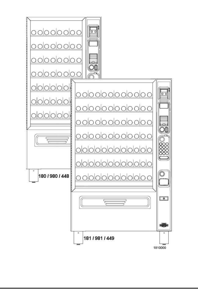
FRONT EXTERIOR VIEWS
1810025 |
1 |
August 2009 |
Initial Setup |
Merchant™ Operators’ Guide |
|||||||||||
|
|
|
|
|
|
|
|
|
|
|
|
|
|
|
|
|
|
|
|
|
|
|
|
|
|
|
|
|
|
|
|
|
|
|
|
|
|
|
|
|
|
|
|
|
|
|
|
|
|
|
|
|
|
|
|
|
|
|
|
|
|
|
|
|
|
|
|
|
|
|
|
|
|
|
|
|
|
|
|
|
|
|
|
|
|
|
|
|
|
|
|
|
|
|
|
|
|
|
|
|
|
|
|
|
|
|
|
|
|
|
|
|
|
|
|
|
|
|
|
|
|
|
|
|
|
|
|
|
|
|
|
|
|
|
|
|
|
|
|
|
|
|
|
|
|
|
|
|
|
|
|
|
|
|
|
|
|
|
|
|
|
|
|
|
|
|
|
|
|
|
|
|
|
|
|
|
|
|
|
|
|
|
|
|
|
|
|
|
|
|
|
|
|
|
|
|
|
|
|
|
|
|
|
|
|
|
|
|
|
|
|
|
|
|
|
|
|
|
|
|
|
|
|
|
|
|
|
|
|
|
|
|
|
|
|
|
|
|
|
|
|
|
|
|
|
|
|
|
|
|
|
|
|
|
|
|
|
|
|
|
|
|
|
|
|
|
|
|
|
|
|
|
|
|
|
|
|
|
|
|
|
|
|
|
|
|
|
|
|
|
|
|
|
|
|
|
|
|
|
|
|
|
|
|
|
|
|
|
|
|
|
|
|
|
|
|
|
|
|
|
|
|
|
|
|
|
|
|
|
|
|
|
|
|
|
|
|
|
|
|
|
|
|
|
|
|
|
|
|
|
|
|
|
|
|
|
|
|
|
|
|
|
|
|
|
|
|
|
|
|
|
|
|
|
|
|
|
|
|
|
|
|
|
|
|
|
|
|
|
|
|
|
|
|
|
|
|
|
|
|
|
|
|
|
|
|
|
|
|
|
|
|
|
|
|
|
|
|
|
|
|
|
|
|
|
|
|
|
|
|
|
|
|
|
|
|
|
|
|
|
|
|
|
|
|
|
|
|
|
|
|
|
|
|
STANDARD
MODEL 181 - EXTERIOR VIEW
(Models 180, 980, 981, 448 and 449 have similar appearance)
August 2009 |
2 |
1810025 |
Merchant™ Operators’ Guide |
Initial Setup |
|
|
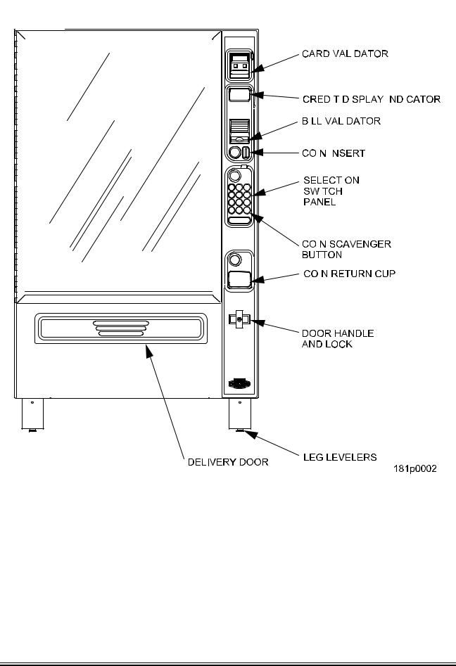
STANDARD
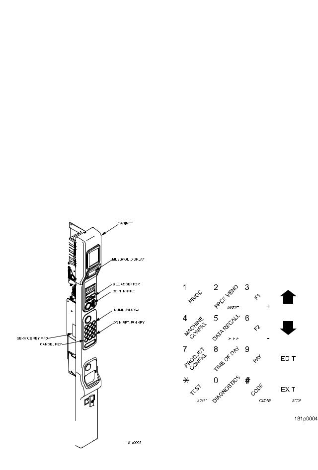
ALL MODELS - MONETARY
1810025 |
3 |
August 2009 |
Initial Setup |
Merchant™ Operators’ Guide |
|
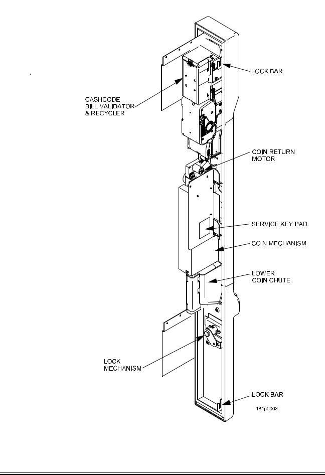
|
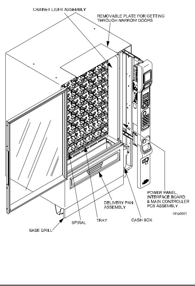
INTERIOR VIEW
August 2009 |
4 |
1810025 |
Merchant™ Operators’ Guide |
Initial Setup |
|
|
Preliminary
Power Requirements
The merchandiser is supplied with a service cord for the country of use and is terminated in a grounding type plug. The wall receptacle used for this merchandiser must be properly polarized, grounded, and of the correct voltage. Operating the merchandiser from a source of low voltage will VOID YOUR WARRANTY. Each merchandiser should have its own 15 Amp electrical circuit and that circuit should be protected with a circuit breaker or fuse conforming to local regulations.
1.Voltage Check - Place the leads of a voltmeter across the LINE (LIVE) and NEUTRAL terminals of the wall receptacle. The voltmeter should indicate 110-130 volts ac for 120 volt, 60 Hz locations, or 220240 volts ac for 230 volt, 50 Hz locations.
2.Polarity Check - Place the leads of a voltmeter across the LINE (LIVE) and GROUND terminals of the wall receptacle. The voltmeter should indicate 110-130 volts ac for 120 volt, 60 Hz locations, or 220240 volts ac for 230 volt, 50 Hz locations.
3.Noise Potential Check - Place the test leads of a voltmeter across the NEUTRAL and GROUND terminals of the wall receptacle. The meter should indicate 0 volts ac. A measurement greater than 1.5 - 2.0 volts ac could result in problems for the merchandiser's electronic circuitry caused by electrical noise.
NOTE
Any deviation from these requirements could result in unreliable performance from your merchandiser.
Unpacking the Merchandiser
Remove all packing materials from the interior of the merchandiser. Keep all documents; warranty cards, etc. Set aside the base plate kit (if present).
1810025 |
5 |
August 2009 |
|
Initial Setup |
Merchant™ Operators’ Guide |
|
|
|
|
Controls and Indicators |
|
INTERLOCK SWITCH
When the monetary slide is open, this switch turns off the optional fan (if so equipped.)
MESSAGE DISPLAY
This is how the merchandiser communicates with the outside world. Customers can see messages about how much money they have put into the merchandiser. The message display also tells customers when a selection is sold out and when vending is free, inhibited, or discounted. The message display shows you what you are doing when you program the merchandiser, and can show you what is wrong if there is a failure.
SELECTION KEYPAD
The customer uses these switches to make selections.
COIN RETURN KEY
Pressing this button returns any coins that have been paid into the merchandiser prior to a vend.
CANCEL KEY
Pressing this button clears any selection keys.
BILL ACCEPTOR (OPTIONAL)
Accepts bills in various denominations, depending upon the type of bill validator, and how the merchandiser is configured.
SERVICE KEYPAD
The service keypad is located on the inside of the monetary section. It gives service personnel the means to program, retrieve data from, and view diagnostic information about, the merchandiser.
|
|
|
|
|
|
|
|
|
|
|
|
|
|
|
|
|
|
|
|
|
|
|
|
|
|
|
|
|
|
|
|
|
|
|
|
|
|
|
|
|
|
|
|
|
|
|
|
|
|
|
|
|
|
|
|
|
|
|
|
|
|
|
|
|
|
|
|
|
|
|
|
|
|
|
|
|
|
|
|
|
|
|
|
|
|
|
|
|
|
|
|
|
|
|
|
|
|
|
|
|
|
|
|
|
|
|
|
|
|
|
|
|
|
|
|
|
|
|
|
|
|
|
|
|
|
|
|
|
|
|
|
|
|
|
|
|
|
|
|
|
|
|
|
|
|
|
|
|
|
|
|
|
|
|
|
|
|
|
|
|
|
|
|
|
|
|
|
|
|
|
|
|
|
|
|
|
|
|
|
|
|
|
|
|
|
|
|
|
|
|
|
|
|
|
|
|
|
|
|
|
|
|
|
|
|
|
|
|
|
|
|
|
|
|
|
|
|
|
|
|
|
|
|
|
|
|
|
|
|
|
|
|
|
|
|
|
|
|
|
|
|
|
|
|
|
|
|
|
|
|
|
|
|
|
|
|
|
|
|
|
|
|
|
|
|
|
|
|
|
|
|
|
|
|
|
|
|
|
|
|
|
|
|
|
|
|
|
|
|
|
|
|
|
|
|
|
|
|
|
|
|
|
|
|
|
|
|
|
|
|
|
|
|
|
|
|
|
|
|
|
|
|
|
|
|
|
|
|
|
|
|
|
|
|
|
|
|
|
|
|
|
|
|
|
|
|
|
|
|
August 2009 |
6 |
1810025 |
|||||||||||
Merchant™ Operators’ Guide |
Initial Setup |
|
|
Controls and Indicators (continued)
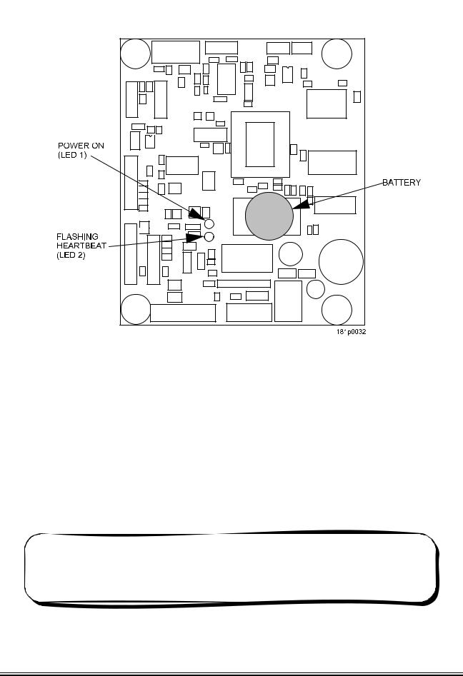
MAIN CONTROLLER PCB DISPLAY
This display consists of two light emitting diodes (LED) mounted on the controller PCB.
POWER ON |
When lit, this red LED indicates electrical power is applied to the |
(L.E.D. 1) |
controller PCB. |
HEARTBEAT |
When flashing, this red LED indicates that the controller PCB is |
(L.E.D. 2) |
active, and the software is operating. |
WARNING
Risk of explosion if battery is replaced with an incorrect type. Battery type is CR2032 / 3V Dispose of used batteries according to the manufacturer's instructions.
NORMAL CONDITIONS:
When the merchandiser is operating normally, you should see a steady red POWER ON indicator and a flashing red HEARTBEAT indicator.
Contact a service representative if any other condition exists.
1810025 |
7 |
August 2009 |
Initial Setup |
Merchant™ Operators’ Guide |
|
|
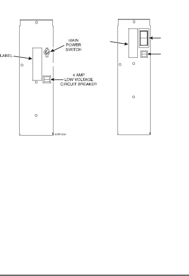
Turning the Merchandiser ON and OFF
|
I |
MAIN |
|
|
POWER |
LABEL |
O |
SWITCH |
|
||
|
|
ELECTRONICS |
|
|
BREAKER |
|
626P0005 |
U.S./CANADA POWER PANEL |
INTERNATIONAL POWER PANEL |
•Power to the merchandiser is controlled by the main power switch, located on the power panel.
•The power panel is on the right side of the merchandiser, behind the monetary door.
WARNING
Lethal voltages are present. Unplug the merchandiser whenever you do one of the following tasks:
•Change the fluorescent lamp.
•Change the ballast.
•Connect or disconnect a harness
(except a motor harness when the tray has been removed.)
Failure to do so may result in personal injury.
August 2009 |
8 |
1810025 |
Merchant™ Operators’ Guide |
Initial Setup |
|
|
Initial Set-Up
Moving the Merchandiser Through a Narrow Doorway
NOTE
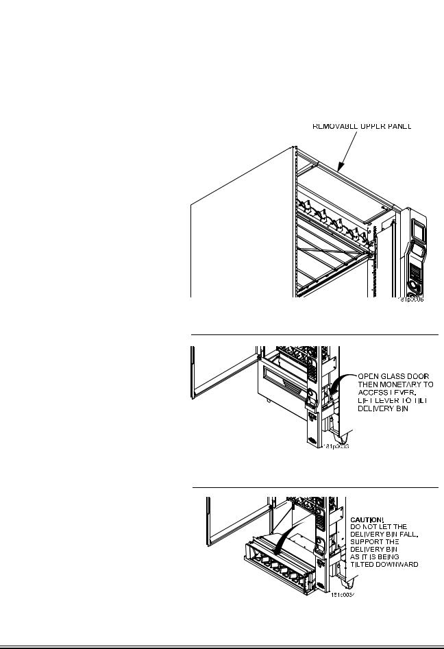
If necessary, this merchandiser can be moved through an opening as narrow as 30 inches by removing panels at the top and bottom of the cabinet.
REMOVING THE TOP PANEL (Refer to Figure 1 at right.)
1.Remove the two screws that secure each end of the panel to the cabinet.
2.Pull the panel forward to remove it from the merchandiser.
REMOVING THE LOWER PANEL AND DELIVERY BIN
(Refer to Figures 2 and 3 at right.)
1.Open the slide-out monetary and the glass door. Locate the silver tab of the delivery bin latch on the lower delivery bin side of the monetary wall.
2.Lift the latch up to allow the delivery bin assembly to hinge down.
3.Lift up the delivery bin slightly and lift up on the drop rods to allow the rods to clear the stop brackets.
4.Slide the delivery bin assembly to the right to clear the hinges. The delivery bin assembly will not be attached to the machine.
5.Unhook the SureVend™ harness at the SureVend™ board, noting the wire routing.
6.Remove the screws that secure the bottom panel to the cabinet.
7.Pull the panel forward to remove it from the cabinet.
NOTE
To fit the merchandiser through some of the most narrow doorways, you may have to remove the trays. If you do, follow the procedure as outlined on the following page.
Figure 1
Figure 2
Figure 3
1810025 |
9 |
August 2009 |
Initial Setup |
Merchant™ Operators’ Guide |
|
|
Moving the Merchandiser Through a Narrow Doorway (continued)
CAUTION
Be careful to not damage the tray harnesses when removing trays from the merchandiser.
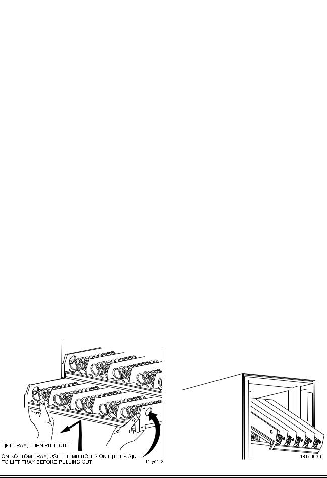
REMOVING THE TRAYS
1.Unplug the tray harnesses from the PCB mounted inside the slide-out monetary.
2.Pull the harnesses through the cabinet.
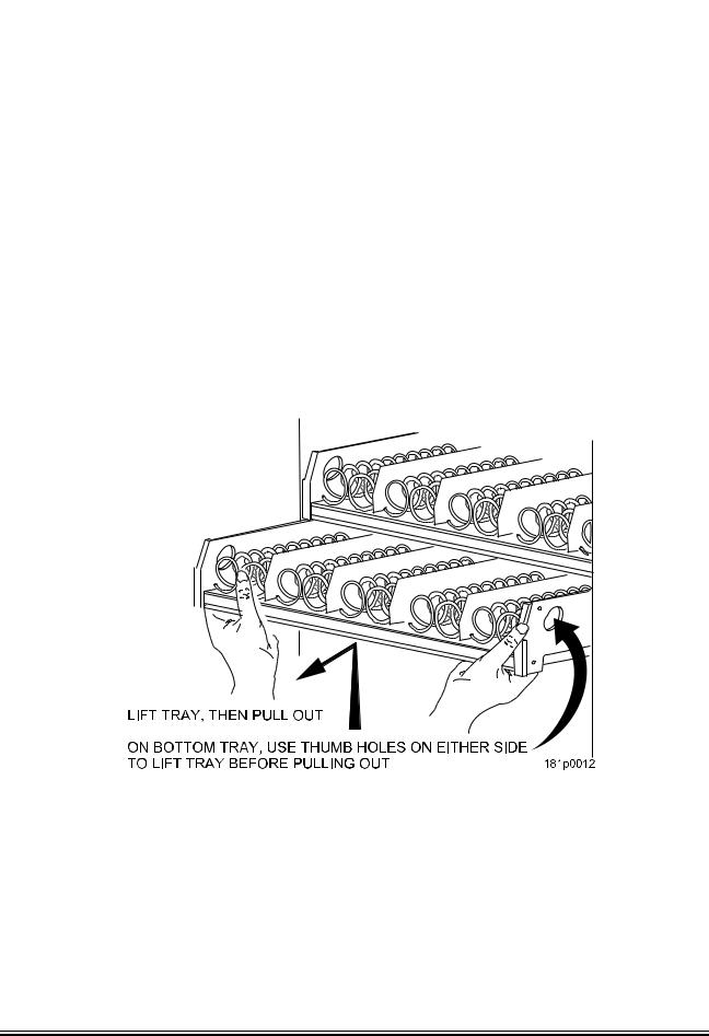
3.Lift up the front of the tray, so that the stop built into the tray clears the roller, then pull the tray forward and let it return to horizontal position.
Pull the tray forward in the horizontal position until the back stop on the tray hits the roller, then lift the tray straight up to clear the roller and remove the tray from the merchandiser.
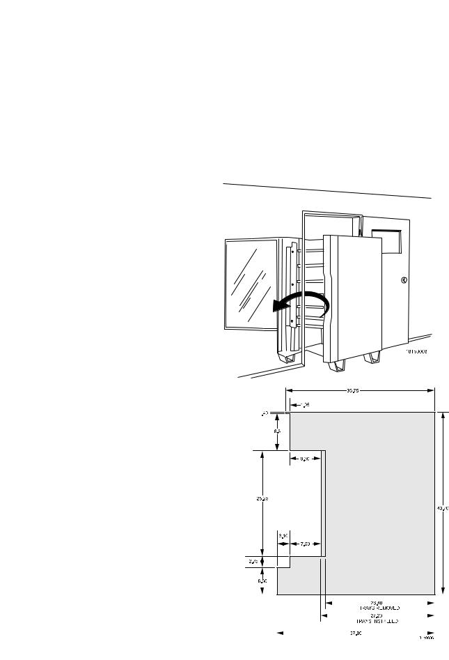
MOVING THE MERCHANDISER THROUGH THE OPENING
1. Open the cabinet door and place it square with the left side of the cabinet.
2. Carefully walk the merchandiser through the opening.
REASSEMBLING THE MERCHANDISER
Replace the upper and lower panels and delivery bin.
If you are not sure that you can fit your merchandiser through the doorway, use the dimensioned drawing to make a cut out in cardboard. The drawing shown has the following removed:
•Delivery bin assembly
•Upper knockout and the anti-theft bar •Lower knockout
•Main Glass Door
•Trays removed if needed
|
|
|
|
|
|
|
|
|
|
|
|
|
|
|
|
|
|
|
|
|
|
|
|
|
|
|
|
|
|
|
|
|
|
|
|
|
|
|
|
|
|
|
|
|
|
|
|
|
|
|
|
|
|
|
|
|
|
|
|
|
|
|
|
|
|
|
|
|
|
|
|
|
|
|
|
|
|
|
|
|
|
|
|
|
|
|
|
|
|
|
|
|
|
|
|
|
|
|
|
|
|
|
|
|
|
|
|
|
|
|
|
|
|
|
|
|
|
|
|
|
|
|
|
|
|
|
|
|
|
|
|
|
|
|
|
|
|
|
|
|
|
|
|
|
|
|
|
|
|
|
|
|
|
|
|
|
|
|
|
|
|
|
|
|
|
|
|
|
|
|
|
|
|
|
|
|
|
|
|
|
|
|
|
|
|
|
|
|
|
|
|
|
|
|
|
|
|
|
|
|
|
|
|
|
|
|
|
|
|
|
|
|
|
|
|
|
|
|
|
|
|
|
|
|
|
|
|
|
|
|
|
|
|
|
|
|
|
|
|
|
|
|
|
|
|
|
|
|
|
|
|
|
|
|
|
|
|
|
|
|
|
|
|
|
|
|
|
|
|
|
|
|
|
|
|
|
|
|
|
|
|
|
|
|
|
|
|
|
|
|
|
|
|
|
|
|
|
|
|
|
|
|
|
|
|
|
|
|
|
|
|
|
|
|
|
|
|
|
|
|
|
|
|
|
|
|
|
|
|
|
|
|
|
|
|
|
|
|
|
|
|
|
|
|
|
|
|
|
|
|
|
|
|
|
|
|
August 2009 |
10 |
|
|
|
|
|
|
|
|
1810025 |
||||||||||
Merchant™ Operators’ Guide |
Initial Setup |
|
|
Positioning the Merchandiser
WARNING
This merchandiser is only rated for installation in an INDOOR location.
Move the merchandiser to its approximate position. (There are some procedures you need to do before it is in its permanent location.) Plug in your merchandiser and turn the power switch to ON.
•You can position this merchandiser anywhere in a bank of machines. It can even be placed on an end flush against a side wall.
•The merchandiser should be located at least one inch away from the back wall.
•There should be enough room in front of the merchandiser for the door to move freely.
Now that you have placed your merchandiser near its permanent location, you need to set up
some of the special options you may have............... |
Go on to the next page and continue with |
the snack section set up. |
|
Snack Section Set-Up
Placing Trays in the Loading Position
WARNING
The bottom tray will rest on the delivery pan assembly. Take care to avoid striking your fingers against the delivery pan assembly.
1.Lift up the front of the tray, so that the stop built into the tray clears the roller, then pull the tray forward and let it return to horizontal position.
2.Continue pulling the tray forward, then when you are able, tilt the tray downward into the loading position as shown below.
1810025 |
11 |
August 2009 |

|
Initial Setup |
Merchant™ Operators’ Guide |
|
|
|
|
Setting Up Trays to Vend Products |
|
These instructions will guide you through setting up your trays for vending. You will be asked to determine if your tray can physically hold the products you intend to vend. If not, you will be directed to other procedures which will help you get them set up. Follow these nine steps for each tray in your merchandiser:
1.Make sure the tray is in the loading position.
2.Is the column wide enough for the intended product? If so, proceed to the next step. Otherwise, set up your tray to vend wider products (see below, this page). When you're done, return to step 3 in this procedure.
3.Will the products fit between the spiral turns? If so, proceed to the next step. Otherwise, change the spiral.
4.Will the product pass under the tray immediately above? If so, proceed to the next step. Otherwise, reposition the tray and guides.
5.Will the product touch products on either side? If not, proceed to the next step. Otherwise, install a product spacer.
6.Load products in the tray.
7.Return the tray to the vending position.
8.Install the price rolls.
9.Install the selection ID numbers.
Setting Up Trays to Vend Wide Products
The following steps will help you configure your trays to vend wide products. When you have completed the procedures called out in each step, return to the next step in the procedure. When you are done with the entire wide product steps, return to the set-up procedures above.
1.Remove the tray from the merchandiser, unplug harness and place on a flat surface.
2.Based on the size of the product you want to vend, decide how many spiral positions it will occupy. Please remember that the leftmost spiral in the group must have an ODD ID number (1, 3, 5, etc.) For example, if a product is three spirals wide, the left spiral will be ID number 1, and the right spiral will be ID number 3. Be careful how wide you set up for, because really wide products could get hung up in the delivery door.
3.Remove the column dividers inside the group. In the example of three spiral positions, you would be removing the dividers between spiral ID numbers 1 and 2, and 2 and 3.
4.If your group only consists of 2 spirals, replace the rightmost motor with a spiral bearing and gear, and install a gear on the leftmost motor. Skip to step 8.
5.Remove all spirals in the group except the leftmost spiral.
6.Do one of the following:
a.If your group has an ODD number of spirals (3, 5, etc.) remove the harnesses from all motors in the group except the leftmost one. To the rightmost motor, connect the harness from the motor immediately to its left.
b.If your group has an EVEN number of spirals (4, 6, etc.) remove the harnesses from all motors inside the group (leave the harnesses connected to the leftmost and rightmost motors).
7.Install a spiral at the rightmost position in your group. Make sure it has the same product capacity and is opposite to the one in the leftmost position.
8.Return the tray to the merchandiser. See “Installing Standard Trays in the Merchandiser” on page 14
9.Electronically couple the motors as needed Return to step 3 in the section “Setting Up Trays to Vend Products” on page 12, above.
August 2009 |
12 |
1810025 |
Merchant™ Operators’ Guide |
Initial Setup |
|
|
Removing Standard Trays
CAUTION
Be careful to not damage the tray harnesses when removing trays from the merchandiser.
NOTE
Study this procedure before you remove a tray for the first time; while you are holding the tray you will not be able to see this area.
1.Unplug the tray harnesses from the PCB mounted inside the slide-out monetary.
2.Pull the harnesses through the cabinet.
3.Lift up the front of the tray, so that the stop built into the tray clears the roller, then pull the tray forward and let it return to horizontal position.
4.Pull the tray forward in the horizontal position until the back stop on the tray hits the roller, then lift the tray straight up to clear the roller and remove the tray from the merchandiser.
1810025 |
13 |
August 2009 |
Initial Setup |
Merchant™ Operators’ Guide |
|
|
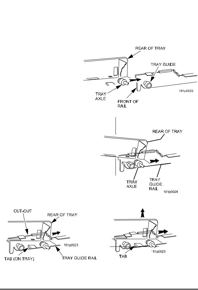
Installing Standard Trays
Study this procedure before you install a tray for the first time; while you are holding the tray you will not be able to see this area.
Proceed as follows:
1. Place the back of the tray in the machine so the back tabs on the tray are behind the tray rail rollers.
2. Slide the tray straight back into the machine, insuring that the tray axle stop is engaged in the tray rail. Keep pushing the tray back until it hits the front stop.
3. Lift the front of the tray, so the stop built into the tray clears the roller. Push the tray forward and let it return to horizontal. It will “lock in” to place.
4.Load the tray harnesses into the
cabinet, over the tray rail and into the cabinet behind the slide out monetary. Reach through the hole provided in the monetary section and grab the tray harness. Plug the Tray harness into the correct PCB tray harness header.
5.Slide the harnesses up into the
round hole provided and secure them with the plastic grommet. Pull the slack of the harnesses back into the cabinet.
August 2009 |
14 |
1810025 |
|
Merchant™ Operators’ Guide |
Initial Setup |
|
|
|
|
Removing a Bottle Tray |
|
CAUTION
Be careful to not damage the tray harnesses when removing trays from the merchandiser.
1.Remove all product from the tray.
2.Push down on the left and right front tray latches with your thumbs and slide out the tray as far as it will go.
3.Unplug the tray harnesses from the PCB mounted inside the slide-out monetary.
4.Pull the harnesses through the cabinet.
5.Locate a small lever on each side of the tray, where it attaches to the slide. The left lever will be up, the right will be down. Press down on the left lever and up on the right lever.
6.Pull the tray towards you, off of the slides.
Installing a Bottle Tray
1.Push the slides back into the cabinet until they stop.
2.With the tray held at a 45ºangle (with the back higher than the front), align the lower edge of the rail on the tray with the lower edge of the rail in the cabinet on both sides.
3.Slowly raise the shelf to a horizontal position, and push the shelf all the way back into the cabinet.
4.Push down on the left and right hand front tray latches with your thumbs and slide the tray forward against the intermediate stop to test that the tray is correctly engaged.
5.Re-route the harnesses through the cabinet.
6.Plug the tray harnesses into the PCB mounted inside the slide-out monetary.
NOTE
It is much easier to replace a bottle tray if you have assistance lining up the tray rails and slides.
1810025 |
15 |
August 2009 |
Initial Setup Merchant™ Operators’ Guide
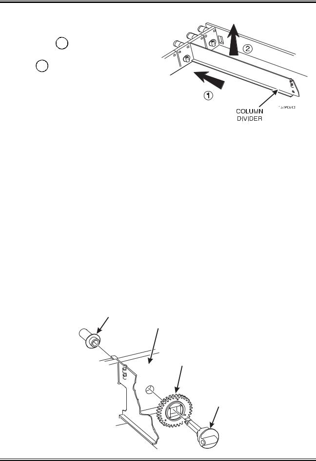
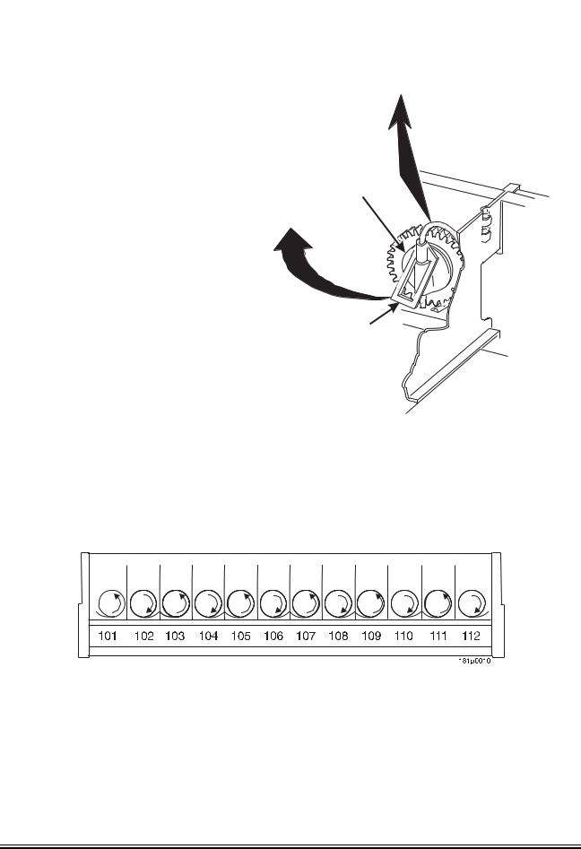
Removing and Installing Column Dividers
1. Push the column divider toward the back of the tray - 1 .
2.Lift the column divider clear of the tray - 2 .
3.Install the column divider in the reverse
order of removal.
Operating Trays Outside the Merchandiser
The tray harnesses are long enough to remove the trays and set the middle and bottom trays on the floor in front of the merchandiser and the top trays on the top of the merchandiser without unplugging the tray harnesses.
Replacing a Motor With a Spiral Bearing
REMOVING A MOTOR
1.Disconnect the harness from the motor.
(See “Connecting and Disconnecting a Motor Harness” on page 17).
2.Remove the spiral. (See “Removing and Installing Spirals” on page 18).
3.Remove the spiral coupler. (See “Removing a Spiral Coupler” on page 20).
4.Remove the motor. (See “Removing and Installing a Spiral Motor” on page 20).
INSTALLING A SPIRAL BEARING
1.Put the gear into position if required in this set-up as shown. (See “Installing a Gear” on page 21).
2.Install the spiral coupler. (See “Installing a Spiral Coupler” on page 22).
A coupled spiral does not use a motor.
SPIRAL
BEARING
BACKWALL
OF TRAY
GEAR
˜
SPIRAL
COUPLER
August 2009 |
16 |
1810025 |
Merchant™ Operators’ Guide |
Initial Setup |
|
|
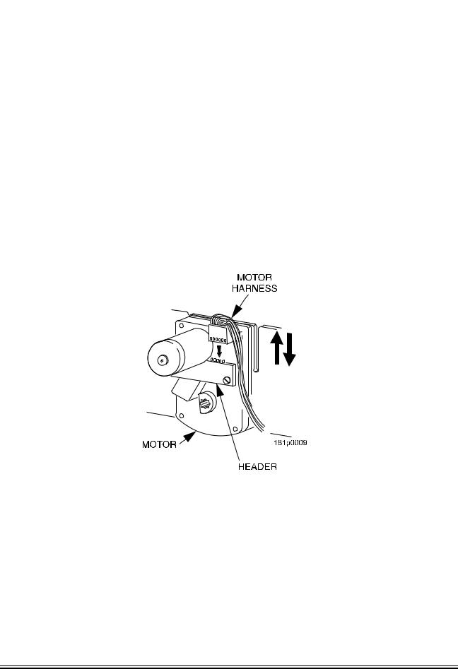
Connecting and Disconnecting a Motor Harness
CAUTION
To avoid breaking the motor circuit board, hold the header on the circuit board whenever connecting or disconnecting a motor harness.
DISCONNECTING A MOTOR HARNESS
1.Pull the harness connector away from the circuit board as shown.
2.Tuck the unused part of the harness out of the way in the trough at the back of the tray.
CONNECTING A MOTOR HARNESS
3.Locate the harness connector for the appropriate tray position.
4.Push the harness connector over the header pins on the motor circuit board as shown.
1810025 |
17 |
August 2009 |
|
Initial Setup |
Merchant™ Operators’ Guide |
|
|
|
|
Removing and Installing Spirals |
|
•All spirals are the same diameter:
•There are two types of spirals:
COUNTER-CLOCKWISE (left hand) |
CLOCKWISE (right hand) |
•Spirals are available in the capacities shown below.
MODELS 180, 181, 980, 981
ITEM CAPACITY |
|
PART NUMBER |
CLIP |
Dimension |
|||
|
|
|
|
Between |
|||
OF SPIRAL |
COUNTER |
|
CLOCKWISE (RH) |
COLOR |
|||
CLOCKWISE (LH) |
Coils |
||||||
|
|
|
|||||
|
|
|
|
|
|
|
|
5 (Optional) |
1477178 |
|
|
1477179 |
Orange |
4.57” |
|
6 (Optional) |
1477102 |
|
|
1477104 |
Purple |
3.78” |
|
9 (Optional) |
1477153 |
|
|
1477150 |
Gray |
2.46” |
|
11 (Standard) |
1477024 |
|
|
1477027 |
Blue |
1.98” |
|
13 (Standard) |
1477030 |
|
|
1477033 |
Yellow |
1.65” |
|
15 (Standard) |
1477036 |
|
|
1477039 |
Red |
1.41” |
|
17 (Standard) |
1477100 |
|
|
1477098 |
Brown |
1.23” |
|
20 (Standard) |
1477042 |
|
|
1477045 |
White |
1.02” |
|
25 (Optional) |
1477048 |
|
|
1477051 |
Green |
.75” |
|
30 (Optional) |
1477054 |
|
|
1477057 |
Black |
.60” |
|
38 (Optional) |
1477060 |
|
|
1477063 |
Orange |
.44” |
|
|
|
|
|
|
|
|
|
|
|
|
MODELS 448, 449 |
|
|
||
4 |
1707048 |
|
|
1707050 |
Green |
3.66” |
|
5 |
1707044 |
|
|
1707046 |
Tan |
2.90” |
|
6 |
1707040 |
|
|
1707042 |
Purple |
2.46” |
|
7 |
1707057 |
|
|
1707059 |
Brown |
2.23” |
|
8 |
1707017 |
|
|
1707019 |
Gray |
1.81” |
|
10 |
1707005 |
|
|
1707007 |
Blue |
1.44” |
|
12 |
1707009 |
|
|
1707011 |
Yellow |
1.18” |
|
14 |
1707013 |
|
|
1707015 |
Red |
1.00” |
|
18 |
1707021 |
|
|
1707023 |
White |
.75” |
|
August 2009 |
18 |
1810025 |
Merchant™ Operators’ Guide |
Initial Setup |
|
|
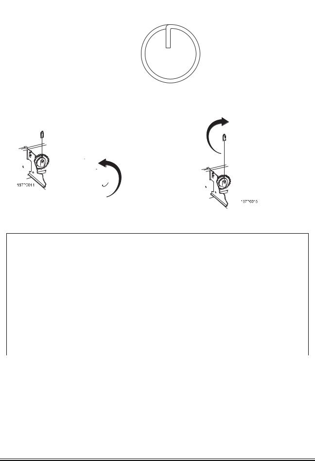
Removing and Installing Spirals (continued)
REMOVING A SPIRAL
1.Pull forward on the retaining clip and
|
remove the end of the spiral from the |
LIFT |
|
spiral coupler as shown. |
|
2. |
Remove the spiral from the tray. |
|
INSTALLING A SPIRAL |
|
|
1. |
Pull the bottom of the retaining clip |
SPIRAL |
|
toward the front of the spiral. |
COUPLER |
|
|
|
2. |
Lower the spiral into the tray column |
PULL |
|
and insert the end of the spiral into |
|
|
the spiral coupler as shown. |
|
3. |
Release the retaining clip. |
|
SPIRAL
RETAINING
CLIP
SHOULD I USE A CLOCKWISE OR A COUNTERCLOCKWISE SPIRAL?
1.The type of spiral used is determined by the column position it will occupy in the tray.
2.Refer to the figure below to find the correct spiral type.
1810025 |
19 |
August 2009 |
Initial Setup |
Merchant™ Operators’ Guide |
|
|
Removing a Spiral Coupler
1.Pinch together the prongs on the end of the spiral coupler as shown.
2.Pull the coupler forward in the direction of the arrow as shown.
SPIRAL
COUPLER
PRONGS
 PULL
PULL
Removing and Installing a Spiral Motor
REMOVING A SPIRAL MOTOR
NOTE
Some steps may already be completed.
1.Remove the tray.
(See “Removing Standard Trays” on page 13).
2.Disconnect the motor harness.
(See “Connecting and Disconnecting a Motor Harness” on page 17).
3.Remove the spiral.
(See“Removing and Installing Spirals” on page 18).
4.Remove the spiral coupler.
(See “Removing a Spiral Coupler” on page 20).
5.Lift the motor clear of the tray.
6.Return the tray to the merchandiser.
SPIRAL
MOTOR
BACKWALL
OF TRAY
GEAR
˜
INSTALLING A SPIRAL MOTOR
1.Remove the tray.
(See “Removing Standard Trays” on page 13).
2.Place the motor in the correct position at the rear of the tray as shown.
3.Place a gear in position if required by this set-up. (See “Installing a Gear” on page 21).
4.Install a spiral coupler in the proper orientation. (See “Installing a Spiral Coupler” on page 22).
5.Connect the motor harness.
(See “Connecting and Disconnecting a Motor Harness” on page 17).
6.Return the tray to the merchandiser.
See “Installing Standard Trays in the Merchandiser” on page 14
SPIRAL
COUPLER
August 2009 |
20 |
1810025 |
Merchant™ Operators’ Guide |
Initial Setup |
|
|
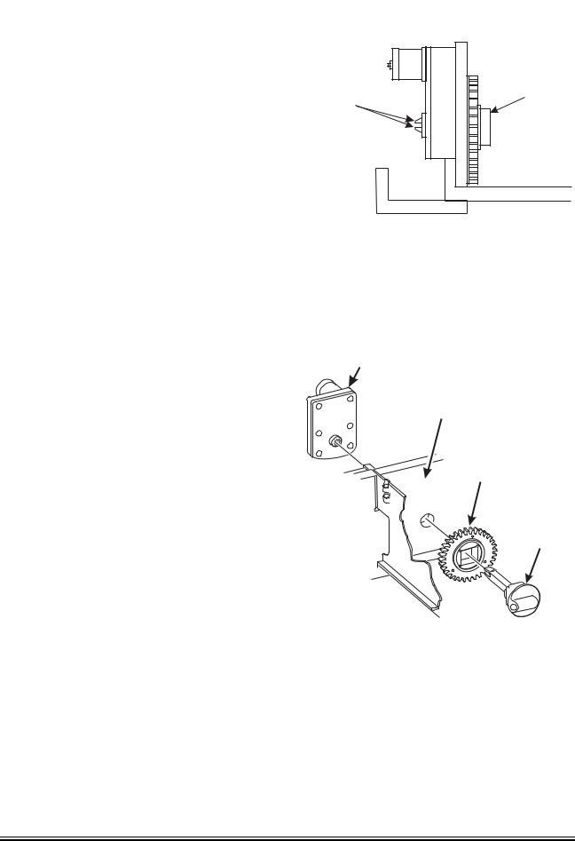
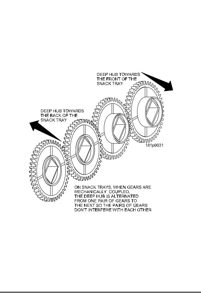
Installing a Gear
WHEN ARE GEARS USED?
•Gears are used to mechanically couple the spirals together.
•This happens whenever you have two spirals and only one motor for vending a selection.
WHERE ARE THE GEARS PLACED?
•The gear is placed between the back of the tray and the spiral coupler.
HOW IS THE GEAR ORIENTED?
•There are two possible orientations for the gear:
•There are two rules to follow when orienting gears:
RULE 1 – The gears for single spiral selections next to each other cannot use the same gear orientation.
RULE 2 – All gears for a single coupled or double spiral selection must use the same orientation.
1810025 |
21 |
August 2009 |
|
Initial Setup |
Merchant™ Operators’ Guide |
|
|
|
|
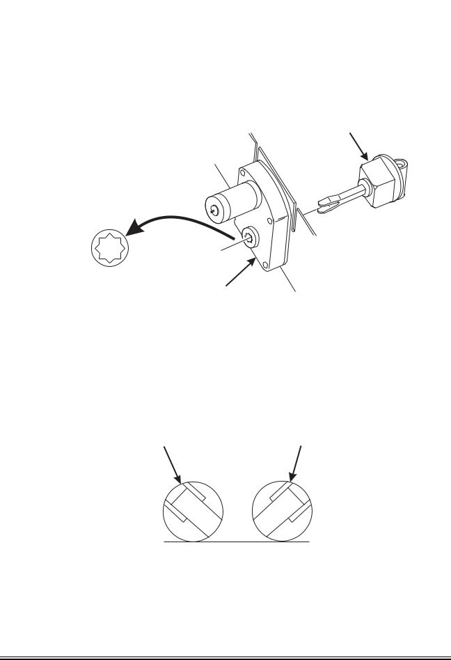
Installing a Spiral Coupler |
|
Place the gear in position if one is required for this set-up. (See “Installing a Gear” on page 21.)
WHEN USED WITH A MOTOR
Hold the motor in place and push the spiral coupler through the motor gear box until it clicks into position. Be sure the spiral couplers are oriented as shown below:
SPIRAL
COUPLER
FRONT VIEW OF |
MOTOR |
|
MOTOR OUTPUT SHAFT |
||
|
NOTE
The motor output shaft opening contains eight facets to allow the spiral coupler to be installed in any one of eight positions.
SPIRAL COUPLER ORIENTATION
ONE POSITION |
ONE POSITION |
COUNTERCLOCKWISE |
CLOCKWISE |
FROM VERTICAL |
FROM VERTICAL |
LEFT SPIRAL |
RIGHT SPIRAL |
COUPLER |
COUPLER |
AS VIEWED FROM FRONT OF TRAY
August 2009 |
22 |
1810025 |
Merchant™ Operators’ Guide |
Initial Setup |
|
|
Installing a Spiral Coupler (continued)
WHEN USED WITH A COUPLER BEARING
Hold the coupler bearing in place and push the spiral coupler through the bearing until the coupler clicks into position. Be sure the coupler is in the proper orientation as shown.
SPIRAL
COUPLER
SPIRAL
BEARING
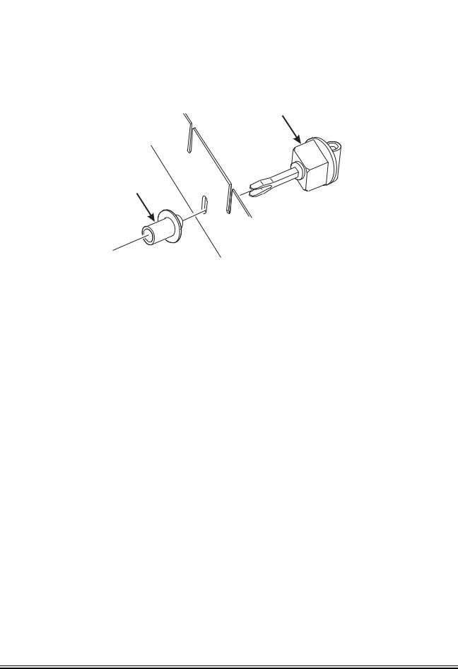
Moving Trays Up or Down
This merchandiser can be adjusted to vend taller products. Some guidelines must be followed:
•Keep in mind that when you increase the product height available to a tray by lowering it, you will be decreasing the product height available to the tray below.
•If a tray is in the lowest position, the tray below it should not be in the highest position.
•If a tray is in the highest position, the tray above it should not be in the lowest position.
•You will need to experiment with various tray positions to get the best results for your products.
Proceed as follows:
1.Remove the tray from the merchandiser. (See“Removing Standard Trays” on page 13).
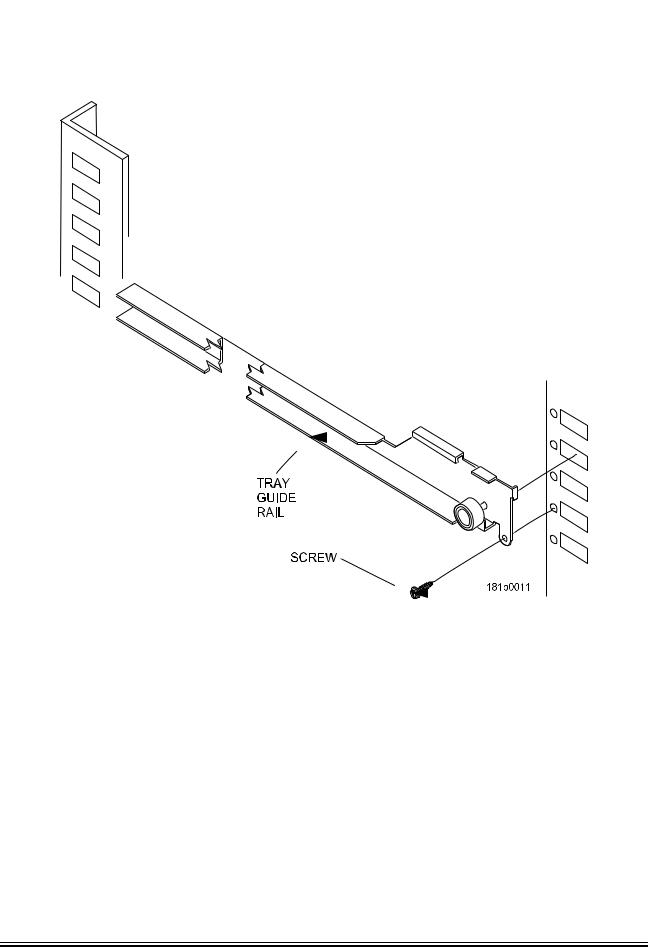
2.Remove the screw that secures the right tray guide rail to the front guide mounting channel as shown.
3.Tap up on the guide rail and unseat the guide rail tabs from the channel slots.
4.Pull the guide rail away from the front and rear guide mounting channels.
5.Move the guide rail to the desired position.
6.Insert the guide rail tabs into the mounting channel slots as shown.
7.Tap down on the guide rail to seat the tabs in the channel slots.
8.Replace the screw that secures the guide rail to the front guide mounting channel.
9.Repeat steps 2 through 8 for the left guide rail.
10.Return the tray to the merchandiser. See “Installing Standard Trays in the Merchandiser” on page 14
1810025 |
23 |
August 2009 |
Initial Setup |
Merchant™ Operators’ Guide |
|
|
Moving Trays Up or Down (continued)
11.Load products into the trays, and perform test vends. Make sure the trays don't interfere with the products you are vending, and that all products vend properly.
August 2009 |
24 |
1810025 |
 Loading...