


 Loading...
Crane Merchandising Systems 167, 177, 168, 457, 458 Installation Manual
...1670097
Models 167, 177, 168, 457, 458, 764, 765, 784, 787
Snack/Refreshment Center 2
Snack Center 4
A |
B |
C |
D |
E |
F |
G |
H |
J |
1 |
2 |
3 |
4 |
5 |
6 |
7 |
8 |
9 |
|
0 |
# |
797
798
|
A |
B |
C |
|
D |
E |
F |
|
G |
H |
J |
|
1 |
2 |
3 |
|
4 |
5 |
6 |
157P0004 |
7 |
8 |
9 |
0 |
# |
||
|
|
|
|
784
787
|
|
A |
B |
C |
|
|
D |
E |
F |
|
|
G |
H |
J |
|
|
1 |
2 |
3 |
|
|
4 |
5 |
6 |
|
|
7 |
8 |
9 |
|
|
0 |
# |
|
A |
B |
C |
|
|
D |
E |
F |
|
|
G |
H |
J |
|
|
1 |
2 |
3 |
|
|
4 |
5 |
6 |
|
|
7 |
8 |
9 |
|
|
0 |
# |
|
|
|
|
|
167 |
|
|
|
|
177 |
|
|
|
|
457 |
|
|
|
|
764 |
|
|
168 |
|
|
|
|
458 |
|
|
|
|
765 |
|
|
|
|
Set-Up & Operators’ Guide
12955 Enterprise Way Bridgeton, Missouri 63044-1200
(314) 298-3500 / Service: (800) 628-8363 www.CraneMS.com
Copyright© 12-06 |
1670097 |

How to use this guide
Since your merchandiser came equipped with a can module, the Snack Center Setup and Operator's Guide has instructed you to get this booklet to continue your setup. Follow the steps for setting up your can module, then return to the spot in the Setup and Operator's Guide that sent you here. You may notice some other books in your plastic bag, also. The Programming Guide is a reference for you to use later, after your machine is up and running. Use the Programming Guide to access the many advanced features included with your machine.
DO NOT DISPOSE OF THIS BOOKLET! Even though you may have finished with it today, you might find the need to set your merchandiser up again. We recommend returning it to the plastic bag, and storing it inside the cabinet. That way, it is readily available at a future time.
This machine has been engineered to our own rigid safety and performance standards. It has been designed to comply with sanitation and health guidelines recommended by the Automatic Merchandising Health-Industry Council (AMHIC) and it conforms with all other NAMA safety recommendations.
This machine has been manufactured in accordance with the safety standards of both Underwriter’s Laboratories and the Canadian Standards Association. To maintain this degree of safety and to continue to achieve the level of performance built into this machine, it is important that installation and maintenance be performed so as to not alter the original construction or wiring, and that replacement parts are as specified in the Parts Manual. Your investment in this equipment will be protected by using this Setup and Operator's Guide and the Parts Manual in your operation, service and maintenance work. By following the prescribed procedures, machine performance and safety will be preserved.

Snack / Refreshment Center Setup and Operator's Guide
Table of Contents
Preliminary.......................................................................................................................................... |
5 |
|
Initial Set-Up ....................................................................................................................................... |
9 |
|
1. |
MOVE THE MERCHANDISER THROUGH A NARROW DOORWAY ............................................... |
9 |
|
remove the top panel: 9 |
|
|
remove the bottom panel: 9 |
|
|
take the merchandiser through the opening: 10 |
|
|
reassemble the merchandiser: 10 |
|
2. |
POSITION THE MERCHANDISER................................................................................................. |
10 |
Snack Section Set-Up........................................................................................................................ |
12 |
|
1. |
PLACE A TRAY IN THE LOADING POSITION.............................................................................. |
12 |
1. |
SET UP TRAYS TO VEND PRODUCTS.......................................................................................... |
13 |
2. |
SET UP A TRAY TO VEND WIDE PRODUCTS............................................................................ |
13 |
3. |
REMOVING A TRAY .................................................................................................................... |
14 |
4. |
REMOVING AND INSTALLING COLUMN DIVIDERS ................................................................... |
16 |
5. |
OPERATE A TRAY OUTSIDE THE MACHINE.............................................................................. |
16 |
1. |
REPLACING A MOTOR WITH A SPIRAL BEARING .................................................................... |
17 |
|
removing a motor: 17 |
|
|
installing a spiral bearing: 17 |
|
|
disconnecting a motor harness: 18 |
|
|
connecting a motor harness: 18 |
|
2. |
CONNECTING AND DISCONNECTING A MOTOR HARNESS ....................................................... |
18 |
3. |
REMOVING AND INSTALLING SPIRALS ...................................................................................... |
19 |
|
to remove a spiral: 20 |
|
|
to install a spiral: 20 |
|
|
should i use a clockwise or a counterclockwise spiral? 20 |
|
1. |
REMOVING A SPIRAL COUPLER ................................................................................................ |
21 |
|
22 |
|
1. |
REMOVING AND INSTALLING A SPIRAL MOTOR ...................................................................... |
22 |
|
removing a spiral motor: 22 |
|
|
installing a spiral motor: 22 |
|
|
when are gears used? 23 |
|
|
where are the gears placed? 23 |
|
|
how is the gear oriented? 23 |
|
2. |
INSTALLING A GEAR................................................................................................................... |
23 |
3. |
INSTALLING A SPIRAL COUPLER ............................................................................................... |
24 |
4. |
MOVING A TRAY UP OR DOWN ................................................................................................. |
26 |
5. |
INSTALLING A TRAY IN THE MERCHANDISER .......................................................................... |
27 |
10. INSTALLING AND REMOVING A PRODUCT SPACER ................................................................ |
28 |
|
|
loading a tray with products in general: 29 |
|
|
special considerations: 29 |
|
1. |
LOAD TRAYS WITH PRODUCT................................................................................................... |
29 |
|
spiral wall retainer usage: 30 |
|
B.. LOAD TRAYS WITH PRODUCT (CONTINUED)......................................................................... |
31 |
|
|
preparing the merchandiser for vending "lunch bucket": 31 |
|
|
preparing the merchandiser for vending "top shelf": 32 |
|
1. |
RETURN THE TRAYS TO THE VENDING POSITION.................................................................... |
33 |
1670097 |
Page i |
December 2005 |

Snack / Refreshment Center Setup and Operator's Guide
|
Table of Contents |
|
|
installing price labels: 34 |
|
2. |
INSTALL AND SET PRICE LABELS.............................................................................................. |
34 |
|
adjusting the price roll: 35 |
|
|
installing selection id numbers: 36 |
|
3. |
INSTALL SELECTION ID LABELS ............................................................................................... |
36 |
|
which id label goes with which selection? 37 |
|
Set Up The Gum and Mint Unit ...................................................................................................... |
38 |
|
1. |
INSTALL PRICE LABELS ............................................................................................................. |
38 |
2. |
PUT THE GUM AND MINT DISPENSER IN THE LOADING POSITION......................................... |
38 |
3. |
LOAD THE GUM AND MINT DISPENSER WITH PRODUCT ........................................................ |
39 |
5. |
REMOVING AND INSTALLING COLUMN REDUCERS.................................................................. |
40 |
|
to remove a column reducer: 40 |
|
|
to install a column reducer: 40 |
|
4. |
RETURN THE GUM AND MINT DISPENSER TO THE VENDING POSITION................................. |
40 |
Final Installation ............................................................................................................................... |
41 |
|
1. |
LEVEL THE MERCHANDISER...................................................................................................... |
41 |
|
method 1: 42 |
|
|
method 2: 42 |
|
1. |
INSTALL THE BASE PLATE ......................................................................................................... |
44 |
3. |
INSTALL THE OPTIONAL CASH BOX LOCK .............................................................................. |
45 |
2. |
INSTALL THE LOCK CYLINDER ................................................................................................. |
45 |
1. |
SET UP THE COIN MECHANISM................................................................................................. |
46 |
1. |
LOAD THE COIN MECHANISM ................................................................................................... |
47 |
Programming .................................................................................................................................... |
48 |
|
|
the service keypad 48 |
|
1. |
SET PRICES ................................................................................................................................. |
48 |
2. |
VIEW THE CHILLER OR CAN UNIT TEMPERATURE ................................................................. |
48 |
Final Checkout .................................................................................................................................. |
49 |
|
1. |
TEST VEND SELECTIONS............................................................................................................ |
49 |
2. |
OPERATIONAL READINESS CHECK ........................................................................................... |
49 |
4. |
SPIRAL INDEXING PROCEDURE |
|
(TWO SPIRALS, ONE OR TWO MOTORS) ......................................................................................... |
50 |
|
3. |
SPIRAL INDEXING PROCEDURE (ONE SPIRAL, ONE MOTOR) ................................................. |
50 |
5. |
TESTING THE BILL VALIDATOR ................................................................................................ |
51 |
December 2005 |
Page ii |
1670097 |
Snack / Refreshment Center Setup and Operator's Guide
A |
B |
C |
D |
E |
F |
G |
H |
J |
1 |
2 |
3 |
4 |
5 |
6 |
7 |
8 |
9 |
|
0 |
# |
797, 798 |
|
|
A |
B C |
|
D |
E |
F |
G H |
J |
|
1 |
2 |
3 |
4 |
5 |
6 |
7 |
8 |
9 |
0 |
# |
|
167, 177 |
|
|
457, 764 |
|
|
A |
B |
C |
D |
E |
F |
G |
H |
J |
1 |
2 |
3 |
4 |
5 |
6 |
7 |
8 |
9 |
|
0 |
# |
784, 787 |
|
|
A |
B C |
|
D |
E |
F |
G H |
J |
|
1 |
2 |
3 |
4 |
5 |
6 |
7 |
8 |
9 |
0 |
# |
|
168, 458 |
|
|
765 |
|
|
157p0296
1670097 |
Page 1 |
December 2005 |
Snack / Refreshment Center Setup and Operator's Guide
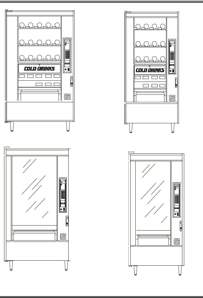
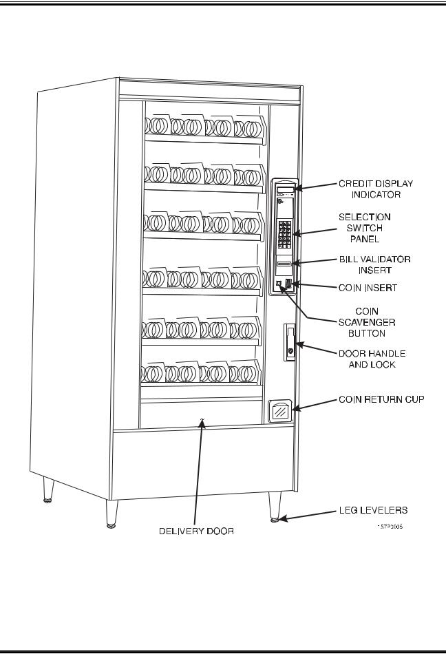
Model 168 - Exterior View
(Models 167, 457, 458, 764, 765 have similar appearance)
December 2005 |
Page 2 |
1670097 |
Snack / Refreshment Center Setup and Operator's Guide
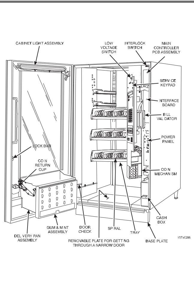
Model 168 - Interior View
(Model 167 has similar appearance)
|
|
|
|
|
|
|
|
|
|
|
|
|
|
|
|
|
|
|
|
|
|
|
|
|
|
|
|
|
|
|
|
|
|
|
|
|
|
|
|
|
|
|
|
|
|
|
|
|
|
|
|
|
|
|
|
|
|
|
|
|
|
|
|
|
|
|
|
|
|
|
|
|
|
|
|
|
|
|
|
|
|
|
|
|
|
|
|
|
|
|
|
|
|
|
|
|
|
|
|
|
|
|
|
|
|
|
|
|
|
|
|
|
|
|
|
|
|
|
|
|
|
|
|
|
|
|
|
|
|
|
|
|
|
|
|
|
|
|
|
|
|
|
|
|
|
|
|
|
|
|
|
|
|
|
|
|
|
|
|
|
|
|
|
|
|
|
|
|
|
|
|
|
|
|
|
|
|
|
|
|
|
|
|
|
|
|
|
|
|
|
|
|
|
|
|
|
|
|
|
|
|
|
|
|
|
|
|
|
|
|
|
|
|
|
|
|
|
|
|
|
|
|
|
|
|
|
|
|
|
|
|
|
|
|
|
|
|
|
|
|
|
|
|
|
|
|
|
|
|
|
|
|
|
|
|
|
|
|
|
|
|
|
|
|
|
|
|
|
|
|
|
|
|
|
|
|
|
|
|
|
|
|
|
|
|
|
|
|
|
|
|
|
|
|
|
|
|
|
|
|
|
|
|
|
|
|
|
|
|
|
|
|
|
|
|
|
|
|
|
|
|
|
|
|
|
|
|
|
|
|
|
|
|
|
|
|
|
|
|
|
|
|
|
|
|
|
|
|
|
|
|
|
|
|
|
|
|
|
|
|
|
|
|
|
|
|
|
|
|
|
|
|
|
|
|
|
|
|
|
|
|
|
|
|
|
|
|
|
|
|
|
|
|
|
|
|
|
|
|
|
|
|
|
|
|
|
|
|
|
|
|
|
|
|
|
|
|
|
|
|
|
|
|
|
|
|
|
|
|
|
|
|
|
|
|
|
|
|
|
|
|
|
|
|
|
|
|
|
|
|
|
|
|
|
|
|
|
|
|
|
|
|
|
|
|
|
|
|
|
|
|
|
|
|
|
|
|
|
|
|
|
|
|
|
|
|
|
|
|
|
|
|
|
|
|
|
|
|
|
|
|
|
|
|
|
|
|
|
|
|
|
|
|
|
|
|
|
|
|
|
|
|
|
|
|
|
|
|
|
|
|
|
|
|
|
|
|
|
|
|
|
|
|
|
|
|
|
|
|
|
|
|
|
|
|
|
|
|
|
|
|
|
|
|
|
|
|
|
|
|
|
|
|
|
|
|
|
|
|
|
|
|
|
|
|
|
|
|
|
|
|
|
|
|
|
|
|
|
|
|
|
|
|
|
|
|
|
|
|
|
|
|
|
|
|
|
|
|
|
|
|
|
|
|
|
|
|
|
|
|
|
|
|
|
|
|
|
|
|
|
|
|
|
|
|
|
|
|
|
|
|
|
|
|
|
|
|
|
|
|
|
|
|
|
|
|
|
|
|
|
|
|
|
|
|
|
|
|
|
|
|
|
|
|
|
|
|
|
|
|
|
|
|
|
|
|
|
|
|
|
|
|
|
|
|
|
|
|
|
|
|
|
|
|
|
|
|
|
|
|
|
|
|
|
|
|
|
|
|
|
|
|
|
|
|
|
|
|
|
|
|
|
|
|
|
|
|
|
|
|
|
|
|
|
|
|
|
|
|
|
|
|
|
|
|
|
|
|
|
|
|
|
|
|
|
|
|
|
|
|
|
|
|
|
|
|
|
|
|
|
|
|
|
|
|
|
|
|
|
|
|
|
|
|
|
|
|
|
|
|
|
|
|
1670097 |
|
|
|
|
|
Page 3 |
|
|
|
|
|
|
|
|
|
|
|
|
|
December 2005 |
|

Snack / Refreshment Center Setup and Operator's Guide
Model 797 - Interior View
|
|
|
|
|
|
|
|
|
|
|
|
|
|
|
|
|
|
|
|
|
|
|
|
|
|
|
|
|
|
|
|
|
|
|
|
|
|
|
|
|
|
|
|
|
|
|
|
|
|
|
|
|
|
|
|
|
|
|
|
|
|
|
|
|
|
|
|
|
|
|
|
|
|
|
|
|
|
|
|
|
|
|
|
|
|
|
|
|
|
|
|
|
|
|
|
|
|
|
|
|
|
|
|
|
|
|
|
|
|
|
|
|
|
|
|
|
|
|
|
|
|
|
|
|
|
|
|
|
|
|
|
|
|
|
|
|
|
|
|
|
|
|
|
|
|
|
|
|
|
|
|
|
|
|
|
|
|
|
|
|
|
|
|
|
|
|
|
|
|
|
|
|
|
|
|
|
|
|
|
|
|
|
|
|
|
|
|
|
|
|
|
|
|
|
|
|
|
|
|
|
|
|
|
|
|
|
|
|
|
|
|
|
|
|
|
|
|
|
|
|
|
|
|
|
|
|
|
|
|
|
|
|
|
|
|
|
|
|
|
|
|
|
|
|
|
|
|
|
|
|
|
|
|
|
|
|
|
|
|
|
|
|
|
|
|
|
|
|
|
|
|
|
|
|
|
|
|
|
|
|
|
|
|
|
|
|
|
|
|
|
|
|
|
|
|
|
|
|
|
|
|
|
|
|
|
|
|
|
|
|
|
|
|
|
|
|
|
|
|
|
|
|
|
|
|
|
|
|
|
|
|
|
|
|
|
|
|
|
|
|
|
|
|
|
|
|
|
|
|
|
|
|
|
|
|
|
|
|
|
|
|
|
|
|
|
|
|
|
|
|
|
|
|
|
|
|
|
|
|
|
|
|
|
|
|
|
|
|
|
|
|
|
|
|
|
|
|
|
|
|
|
|
|
|
|
|
|
|
|
|
|
|
|
|
|
|
|
|
|
|
|
|
|
|
|
|
|
|
|
|
|
|
|
|
|
|
|
|
|
|
|
|
|
|
|
|
|
|
|
|
|
|
|
|
|
|
|
|
|
|
|
|
|
|
|
|
|
|
|
|
|
|
|
|
|
|
|
|
|
|
|
|
|
|
|
|
|
|
|
|
|
|
|
|
|
|
|
|
|
|
|
|
|
|
|
|
|
|
|
|
|
|
|
|
|
|
|
|
|
|
|
|
|
|
|
|
|
|
|
|
|
|
|
|
|
|
|
|
|
|
|
|
|
|
|
|
|
|
|
|
|
|
|
|
|
|
|
|
|
|
|
|
|
|
|
|
|
|
|
|
|
|
|
|
|
|
|
|
|
|
|
|
|
|
|
|
|
|
|
|
|
|
|
|
|
|
|
|
|
|
|
|
|
|
|
|
|
|
|
|
|
|
|
|
|
|
|
|
|
|
|
|
|
|
|
|
|
|
|
|
|
|
|
|
|
|
|
|
|
|
|
|
|
|
|
|
|
|
|
|
|
|
|
|
|
|
|
|
|
|
|
|
|
|
|
|
|
|
|
|
|
|
|
|
|
|
|
|
|
|
|
|
|
|
|
|
|
|
|
|
|
|
|
|
|
|
|
|
|
|
|
|
|
|
|
|
|
|
|
|
|
|
|
|
|
|
|
|
|
|
|
|
|
|
|
|
|
|
|
|
|
|
|
|
|
|
|
|
|
|
|
|
|
|
|
|
|
|
|
|
|
|
|
|
|
|
|
|
|
|
|
|
|
|
|
|
|
|
|
|
|
|
|
|
|
|
|
|
|
|
|
|
|
|
|
|
|
|
|
|
|
|
|
|
|
|
|
|
|
|
|
|
|
|
|
|
|
|
|
|
|
|
|
December 2005 |
|
|
|
|
|
Page 4 |
1670097 |
||||||||||||||

Snack / Refreshment Center Setup and Operator's Guide
Preliminary
Power Requirements
The merchandiser is supplied with a service cord for the country of use and is terminated in a grounding type plug. The wall receptacle used for this merchandiser must be properly polarized, grounded, and of the correct voltage. Operating the merchandiser from a source of low voltage will VOID YOUR WARRANTY. Each merchandiser should have its own electrical circuit and that circuit should be protected with a circuit breaker or fuse conforming to local regulations.
1.Voltage Check - Place the leads of a voltmeter across the LINE (LIVE) and NEUTRAL terminals of the wall receptacle. The voltmeter should indicate 110-130 volts ac for 120 volt, 60 Hz locations, or 220240 volts ac for 230 volt, 50 Hz locations.
2.Polarity Check - Place the leads of a voltmeter across the LINE (LIVE) and GROUND terminals of the wall receptacle. The voltmeter should indicate 110-130 volts ac for 120 volt, 60 Hz locations, or 220240 volts ac for 230 volt, 50 Hz locations.
3.Noise Potential Check - Place the test leads of a voltmeter across the NEUTRAL and GROUND terminals of the wall receptacle. The meter should indicate 0 volts ac. A measurement greater than 1.5 - 2.0 volts ac could result in problems for the merchandiser's electronic
circuitry caused by electrical noise.
Any deviation from these requirements could result in unreliable performance from your merchandiser.
Unpack the Machine
Remove all packing materials from the interior of the machine. Keep all documents; warranty cards, etc. Set aside the base plate kit (if present).
1670097 |
Page 5 |
December 2005 |
Snack / Refreshment Center Setup and Operator's Guide
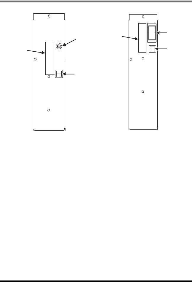
Controls and Indicators
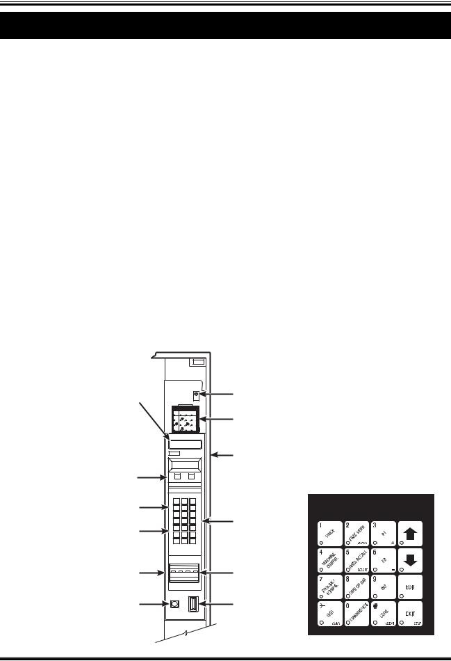
INTERLOCK SWITCH. When the cabinet door is open, this switch turns off the glass heater, optional fan (if so equipped) and turns on the service light (not present on all models).
LOW VOLTAGE SWITCH. Informs the controller software of the main door open or closed status.
MESSAGE DISPLAY. This is how the merchandiser communicates with the outside world. Customers can see messages about how much money they have put into the merchandiser. The message display also tells customers when a selection is sold out and when vending is free, inhibited, or discounted. The message display shows you what you are doing when you program the merchandiser, and can show you what is wrong if there is a failure.
FREE VEND KEYSWITCH (OPTIONAL). This allows someone (other than maintenance personnel) to set the merchandiser to free vend without opening the door.
SELECTION SWITCH PANEL. The customer uses these switches to make selections. Also, maintenance people may use this switch panel during programming and other support modes.
COIN RETURN BUTTON. Pressing this button returns any coins that have been paid into the merchandiser prior to a vend.
BILL ACCEPTOR (OPTIONAL). Accepts bills in various denominations, depending upon the type of bill validator, and how the machine is configured.
SERVICE KEYPAD. The service keypad is located at the top of the monetary panel. It gives service personnel the means to program, retrieve data from, and view diagnostic information about, the
merchandiser.

 INTERLOCK SWITCH
MESSAGE |
LOW VOLTAGE |
DISPLAY |
SWITCH |
|
|
|
FREE |
|
|
|
|
TEST |
FREE |
|
|
|
PRICE |
DATA VEND |
VEND |
SERVICE |
|
|
CONF. |
PAYOUT |
PROD. |
||
|
|
|
DRY |
KEYPAD |
|
|
OF |
SERVICE |
ENTER/ |
||
|
|
HOME |
LIQUID |
|
|
|
|
PROD. |
|
||
|
TIME |
|
|
|
|
|
DAY |
|
ACTION |
|
|
|
CRANE |
NATIONAL VENDORS |
CABINET |
||
|
|
INSERT |
|
|
|
ACT |
|
COINS |
|
|
|
|
OR |
|
|
||
DOLLAR BILLS |
|
||||
CREDIT |
|
YOUR |
|
|
|
|
|
MAKE |
|
|
|
CARD READER |
|
SELECTION |
|
|
|
CHANGE RETURNED BELOW |
|
||||
LETTERS |
A |
B |
C |
|
|
D |
E |
F |
|
||
A-H,J |
|
||||
G |
H |
J |
SELECTION |
||
|
|||||
|
1 |
2 |
3 |
||
|
SWITCH |
||||
NUMERALS |
4 |
5 |
6 |
||
1-9, *,0, # |
7 |
8 |
9 |
|
|
0 |
# |
|
|||
|
|
||||
MONETARY |
BILL |
PANEL |
ACCEPTOR |
COIN
RETURN
COIN
BUTTON
INSERT
157P0086
December 2005 |
Page 6 |
1670097 |
Snack / Refreshment Center Setup and Operator's Guide
Controls and Indicators (continued)
MAIN CONTROLLER
PCB ASSEMBLY
LED1 LED2 |
POWER ON |
FLASHING |
(LED 1) |
HEARTBEAT |
|
(LED 2) |
MAIN CONTROLLER PCB DISPLAY. This display consists of two light emitting diodes (LED) mounted on the controller PCB.
POWER ON |
When lit, this red LED indicates electrical power is applied to |
(L.E.D. 1) |
the controller PCB. |
HEARTBEAT |
When flashing, this red LED indicates that the controller PCB |
(L.E.D. 2) |
is active, and the software is operating. |
"CAUTION - Risk of explosion if battery is replaced with an incorrect type. Dispose of used batteries according to the manufacturer's instructions."
NORMAL CONDITIONS:
When the merchandiser is operating normally, you should see a steady red POWER ON indicator and a flashing red HEARTBEAT indicator. Contact a service representative if any other condition exists.
Back Side of U.S./Canada Power Panel. The circuit board mounted on the rear of the power panel is a dc power supply for the coin mechanism. A fuse protects the board circuitry in the event of a coin mechanism solenoid failure. If the coin mechanism is not working, check this fuse. If the fuse is blown, a bad coin mechanism solenoid could be at fault. (Board may not be there if machine is setup for MDB.)
|
TOP |
DC POWER |
AGC 1 |
SUPPLY PCB |
FUSE |
FOR 110V COIN MECH |
1 AMP |
|
˜ |
BACK SIDE
OF
U.S. / CANADA POWER CONTROL PANEL
How to Turn the Merchandiser ON and OFF
1670097 |
Page 7 |
December 2005 |
Snack / Refreshment Center Setup and Operator's Guide
|
|
|
|
I |
MAIN |
|
|
MAIN |
LABEL |
|
POWER |
|
|
O |
SWITCH |
||
|
|
POWER |
|||
|
|
|
|||
|
|
|
|
|
|
|
ON |
SWITCH |
|
|
|
LABEL |
OFF |
|
|
|
ELECTRONICS |
|
|
|
|
|
BREAKER |
LOW VOLTAGE
CIRCUIT BREAKER
626P0039 |
626P0005 |
U.S./CANADA POWER PANEL |
INTERNATIONAL POWER PANEL |
•Power to the merchandiser is controlled by the main power switch, located on the power panel.
•The power panel is on the right side of the merchandiser, behind the monetary door.
WARNING
Lethal voltages are present. Unplug the merchandiser whenever you do one of the following tasks:
•Change a fuse
•Change the fluorescent lamp
•Change the lamp starter
•Connect or disconnect a harness (except a motor harness when the tray has been removed)
Failure to do so may result in personal injury.
December 2005 |
Page 8 |
1670097 |

Snack / Refreshment Center Setup and Operator's Guide
Initial Set-Up
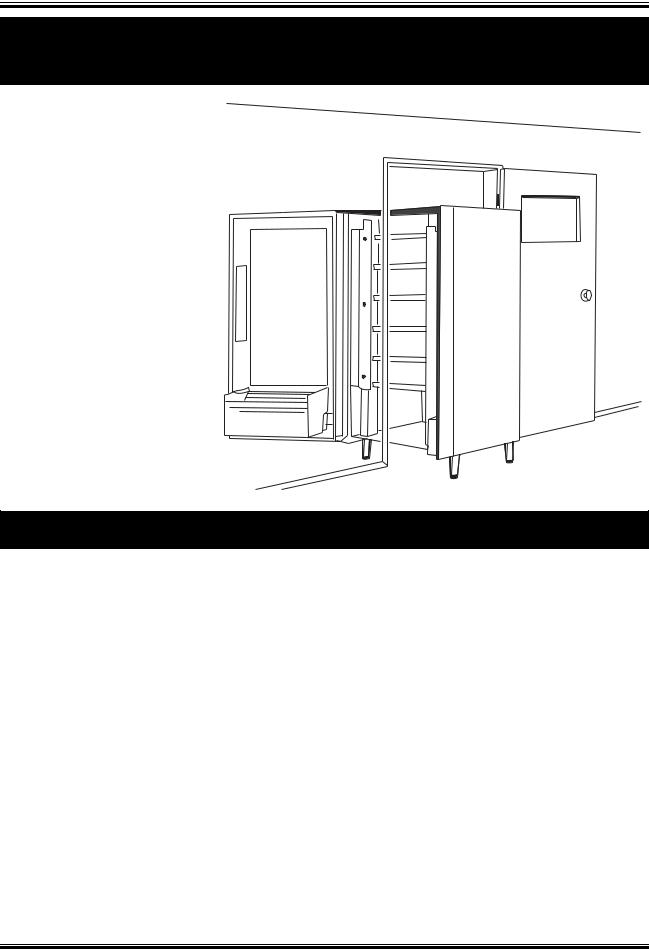
1. Move the Merchandiser Through a Narrow Doorway
NOTE: If necessary, this merchandiser can be moved through an opening as narrow as 30 inches by removing panels at the top and bottom of the cabinet. Merchandisers 457 and 458 are only 28” deep, and do not require panels to be removed.
REMOVE THE TOP PANEL:
1.Remove the two screws that secure each end of the panel to the cabinet.
2.Pull the panel forward to remove it from the merchandiser.
REMOVE THE BOTTOM PANEL:
1.Remove the screws that secure the panel to the cabinet.
2.Pull the panel forward to remove it from the cabinet.
REMOVABLE PANEL FOR GETTING THROUGH A NARROW DOORWAY
VIEW LOOKING INTO THE TOP OF THE CABINET
REMOVABLE PANEL
FOR GETTING THROUGH
A NARROW DOORWAY
˜
VIEW LOOKING INTO THE BOTTOM OF THE CABINET
1670097 |
Page 9 |
December 2005 |
Snack / Refreshment Center Setup and Operator's Guide
1. Move the Merchandiser Through a Narrow Doorway
(continued)
TAKE THE MERCHANDISER
THROUGH THE OPENING:
1.Open the cabinet door and place it square with the
left side of the cabinet.
2. Carefully walk the merchandiser through the opening.
REASSEMBLE THE MER-
CHANDISER:
1.Replace the upper and lower panels.
2. Position the Merchandiser
Move the merchandiser to its approximate position. (There are some procedures you need to do before it is in its permanent location.) Plug in your merchandiser and turn the power switch to ON.
•You can position this merchandiser anywhere in a bank of machines. It can even be placed on an end flush against a side wall.
•The 167 and 168 merchandisers should be located at least one inch away from the back wall.
•The 764, 765, 784, 787, 797, and 798 merchandisers should be placed at least six inches away from the back wall. This will provide adequate air circulation for the refrigeration unit.
•The 764, 765, 787, 797, and 798 merchandisers will operate more efficiently when placed in a shaded location.
•There should be enough room in front of the merchandiser for the door to move freely.
WARNING
This machine is only rated for installation in an indoor location.
December 2005 |
Page 10 |
1670097 |

Snack / Refreshment Center Setup and Operator's Guide
Time Out!
Now that you have placed your machine near its permanent location, you need to set up some of the special options you may have.
NOW, IF YOUR MACHINE IS EQUIPPED WITH A CAN-
MODULE . . .
Grab the booklet entitled "CAN MODULE SETUP AND OPERATOR'S GUIDE" and follow the setup procedures contained in it. After you have done that, come right back here and proceed with the next step.
N |
E |
X |
T |
Go on to the next page and continue with the snack set up.
1670097 |
Page 11 |
December 2005 |
Snack / Refreshment Center Setup and Operator's Guide
Snack Section Set-Up
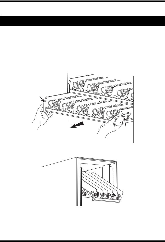
1.Place a Tray in the Loading Position
2.Place both hands on the tray as shown.
3.If your machine has tray latches, lightly push back on the tray with your palms. This will release the tray latches on the sides of the tray. Otherwise, skip to step 5.
4.Push down on the tray latches with your thumbs.
5.Pull the tray toward you until you hear and feel the rear tray rollers drop into a cut-out in the top of the guide rail. Skip to step 6
6.Lightly lift the front of the tray and pull the tray toward you until you hear and feel the tray rollers drop into the cut-out in the top of the guide rail.
.
TRAY
LATCH
PULL
TRAY
LATCH
157P0011
7.Continue pulling the tray forward for another inch. You will then be able to tilt the tray downward into the loading position as shown.
NOTE
When the cabinet door is not fully open, the bottom tray will rest on the delivery pan assembly. Handle the tray with care to avoid scratching the delivery pan assembly.
December 2005 |
Page 12 |
1670097 |

Snack / Refreshment Center Setup and Operator's Guide
1. Set up Trays to Vend Products
These instructions will guide you through setting up your trays for vending. You will be asked to determine if your tray can physically hold the products you intend to vend. If not, you will be directed to other procedures which will help you get them set up. Follow these nine steps for each tray in your machine:
1.Make sure the tray is in the loading position.
2.Is the column wide enough for the intended product? If so, proceed to the next step. Otherwise, set up your tray to vend wider products (see below, this page). When you're done, return to step 3 in this procedure.
3.Will the products fit between the spiral turns? If so, proceed to the next step. Otherwise, change the spiral.
4.Will the product pass under the tray immediately above? If so, proceed to the next step. Otherwise, reposition the tray and guides.
5.Will the product touch products on either side? If not, proceed to the next step. Otherwise, install a product spacer.
6.Load products in the tray.
7.Return the tray to the vending position.
8.Install the price rolls.
9.Install the selection ID numbers.
2.Set Up A Tray To Vend Wide Products
The following steps will help you configure your tray to vend wide products. When you have completed the procedures called out in each step, return to the next step in the procedure. When you are done with the entire wide product steps, return to the set-up procedures above.
1.Remove the tray from the merchandiser and place on a flat surface.
2.Based on the size of the product you want to vend, decide how many spiral positions it will occupy. Please remember that the leftmost spiral in the group must have an even ID number (0, 2, 4, etc.) For example, if a product is three spirals wide, the left spiral will be ID number 0, and the right spiral will be ID number 2. Be careful how wide you set up for, because really wide products could get hung up in the delivery door.
3.Remove the column dividers inside the group. In the example of three spiral positions, you would be removing the dividers between spiral ID numbers 0 and 1, and 1 and 2.
4.If your group only consists of 2 spirals, replace the rightmost motor with a spiral bearing and gear, and install a gear on the leftmost motor. Skip to step 8.
5.Remove all spirals in the group except the leftmost spiral.
6.Do one of the following:
a.If your group has an ODD number of spirals (3, 5, etc.) remove the harnesses from all motors in the group except the leftmost one. To the rightmost motor, connect the harness from the motor immediately to its left.
b.If your group has an EVEN number of spirals (4, 6, etc.) remove the harnesses from all motors inside the group (leave the harnesses connected to the leftmost and rightmost motors).
1670097 |
Page 13 |
December 2005 |
Snack / Refreshment Center Setup and Operator's Guide
7.Install a spiral at the rightmost position in your group. Make sure it has the same product capacity and is opposite to the one in the leftmost position.
8.Return the tray to the merchandiser.
9.Electronically couple the motors as needed (see your Programming Guide for information).
10.Return to step 3 in the Set Up Trays to Vend Products procedure, above.
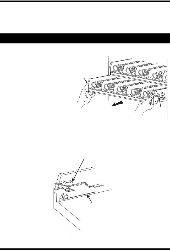
3.Removing a Tray
Study this procedure before you install a tray for the first time; while you are holding the tray you will not be able to see this area. Proceed as follows:
1.If your machine has tray latches, push with your palms. This releases the tray latches. Otherwise, skip to step 4.
2.Push down on the tray latches with your thumbs.
3.Pull the tray forward until you hear and feel the rear tray rollers drop into a cut-out in the top of the guide rail.
TRAY
LATCH
PULL
TRAY
LATCH
157P0011
4.Lightly lift the front of the tray and pull the tray toward you until you hear and feel the rear tray rollers drop into a cut-out in the top of the guide rail.
TRAY
LATCH
TRAY
GUIDE
RAIL
157P0027
December 2005 |
Page 14 |
1670097 |
Loading...