


Crane Merchandising Systems 610, 611, 625, 626, 629 Installation Manual
...INSTALLATION &
OWNER’S MANUAL
|
|
Series: |
|
610, 611, 625, 626, 629, 630, 635, 640, 642, 645, |
|
|
650, 675, 676, 711, 712, 725, 770, 775, 782, 783 |
|
|
Certified to: |
|
|
ANSI Z21.97/CSA 2.41 |
|
|
for outdoor decorative |
|
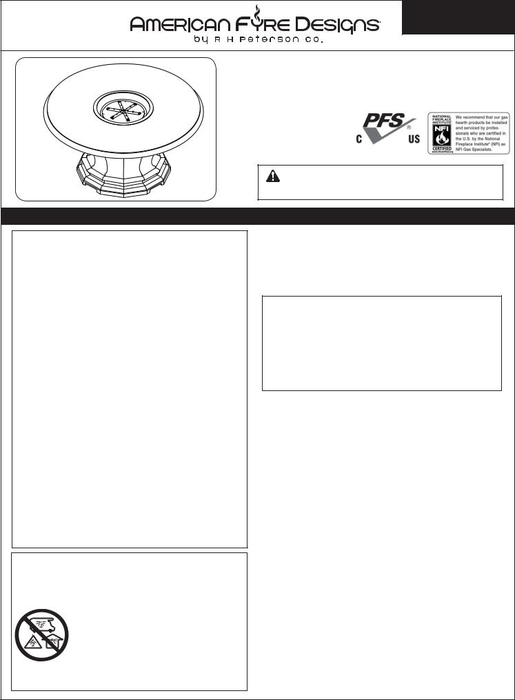
629 |
gas appliances |
F13-042 |
|
|
|
series |
WARNING: For Outdoor Use Only |
|
shown |
||
OUTDOOR FIRETABLES
 WARNING: If the information in this manual is not followed exactly, a fire or explosion may result causing property damage, personal injury or loss of life.
-Do not store or use gasoline or other flammable vapors and liquids in the vicinity of this or any other appliance.
-A propane cylinder not connected for use shall not be stored in the vicinity of this or any other appliance.
 DANGER
If you smell gas:
1.Shut off gas to the appliance.
2.Extinguish any open flame.
3.If odor continues, keep away from the appliance and immediately call your gas supplier or fire department.
Installation and service must be performed by an NFI Certified or other qualified professional installer, service agency, or gas supplier.
 DANGER
CARBON MONOXIDE HAZARD
This appliance can produce carbon monoxide which has no odor.
Using it in an enclosed space can kill you.
Never use this appliance in an enclosed space such as a camper, tent, car, or home.
INSTALLER & CONSUMER: These instructions MUST be retained with this appliance for future reference.
Important: Read these instructions carefully before starting installation of the unit.
 WARNING
Improper installation, adjustment, alteration, service, or maintenance can cause property damage, personal injury, or loss of life. Read the installation, operating and maintenance instructions thoroughly before installing or servicing this equipment.
This appliance is designed as an attended appliance. Adults must be present when the unit is operating. DO NOT leave this unit burning when unattended. If this product is left burning unattended, it may cause damage or serious injury.
IMPORTANT
For safe operation and proper performance of this product and to comply with certification, listings, and building code acceptances, use ONLY Peterson AFD controls, parts, and accessories that have been specifi cally listed or certifi ed for use with this burner system. Use of other controls, parts, or accessories is prohibited and will void all warranties, certifi cations, listings, and building code approvals, and may cause property damage, personal injury, and loss of life.
CODE AND SUPPLY REQUIREMENTS:
The installation must conform with local codes and ordinances, or, in the absence of local codes, with the latest National Fuel Gas Code, ANSI Z223.1.
Robert H. Peterson Co. • 14724 East Proctor Avenue • City of Industry, CA 91746
REV 1 - 1401211330 1 L-H2-002
INSTALLATION ET
MODE D'EMPLOI
|
Series: |
|
610, 611, 625, 626, 629, 630, 635, 640, 642, 645, |
|
650, 675, 676, 711, 712, 725, 770, 775, 782, 783 |
|
Certifié à: |
|
ANSI Z21.97/CSA 2.41 |
|
pour les appareils à gaz |
|
décoratifs extérieurs |
Série |
F13-042 |
|
|
629 |
AVERTISSEMENT: Pour l'usage extérieur |
montré |
seulement |
FIRETABLES PLEIN AIR
 AVERTISSEMENT: Si l'information en ce manuel n'est pas suivie exactement, une incendie ou une explosion peut résulter entraînant des dégats matériels, le dommage corporel ou des pertes humaines.
-Ne pas entreposer ni utiliser d'essence ou d'autres vapeurs et liquides inflammables à proximité de cet appareil ou de tout autre.
-Une bouteille de propane non branchée ne doit pas être entreposée à proximité de cet ou tout autre appareil.
 DANGER
Si vous sentez une odeur de gaz:
1.Coupez le gaz à l'appareil.
2.Éteindre toute flamme nue.
3.Si l'odeur persiste, éloignez-vous de l'appareil et appelez immédiatement votre fournisseur de gaz ou les pompiers.
L'installation et le service doivent être assurés par un NFI certifié ou toute autre installateur, agence de service, ou fournisseur professionnelle qualifiée de gaz.
 DANGER
DANGER MONOXYDE DE CARBONE
Cet appareil peut produire du monoxyde de carbone n'a pas d'odeur qui.
Son utilisation dans un espace clos
peut vous tuer.
Ne jamais utiliser cet appareil dans un espace clos comme une caravane, tente, véhicule ou maison.
d'INSTALLATEUR; CONSOMMATEUR: Ces instructionsDOIVENTêtremaintenues aveccet appareil pour la future référence.
Important: Lisez ces instructions soigneusement avant de commencer l'installation de l'unité.
 AVERTISSEMENT L'installation, l'ajustement, le changement, le service, ou l'entretien inexact peuvent causer des dégats matériels, le dommage corporel, ou des pertes humaines. Lisez l'installation, l'opération et les instructions d'entretien complètement avant d'installer ou entretenir cet équipement.
Cet appareil est conçu comme appareil occupé. Les adultes doivent être présent quand l'unité fonctionne. Ne laissez pas ce burning d'unité si sans surveillance. Si ce produit est laissé sans surveillance brûlant, il peut causer des dommages ou des dommages sérieux.
IMPORTANT
Pour l'exploitation sûre et l'exécution appropriée de ce produit et pour se conformer à la certifi cation, aux listes, et aux acceptations de codes du bâtiment, commandes, pièces, et accessoires de Peterson d'utilisation SEULEMENT qui ont été spécifiquement énumérés ou certifiés pour l'usage avec ce système de brûleur. L'utilisation d'autres commandes, pièces, ou accessoires est interdite et videra toutes les garanties, certifi cations, listes, et approbations de codes du bâtiment, et peut causer des dégats matériels, le dommage corporel, et des pertes humaines.
CONDITIONS DE CODE ET D'APPROVISIONNEMENT:
L'installation doit se conformer aux codes locaux et aux ordonnances, ou, en l'absence des codes locaux, au plus défunt code national de gaz de carburant, la norme ANSI Z223.1.
REV 1 - 1401211330 |
2 |
L-H2-002 |

TABLE OF CONTENTS
GETTING STARTED |
|
PRE-INSTALLATION AND PREPARATION SAFETY GUIDELINES |
.....................................................4 |
INSTALLATION SAFETY GUIDELINES................................................................................................... |
5 |
OPERATING THE UNIT SAFELY AND CORRECTLY ............................................................................. |
5 |
NOTES PAGE................................................................................................................................................ |
6 |
SAFE USE & MAINTENANCE OF PROPANE GAS CYLINDERS.......................................................... |
7 |
SPECIFICATIONS AND DIMENSIONS...................................................................................................... |
9 |
MINIMUM CLEARANCES TO COMBUSTIBLES................................................................................. |
10 |
PARTS LIST................................................................................................................................................. |
11 |
INSTALLATION |
|
IMPORTANT SAFETY INFORMATION.................................................................................................. |
15 |
FIRETABLE INSTALLATION .................................................................................................................. |
15 |
BEFORE YOU BEGIN ........................................................................................................................... |
15 |
LOCATION .......................................................................................................................................... |
15 |
FIRETABLE ASSEMBLY: ONE-PIECE MODELS .................................................................................... |
16 |
FIRETABLE ASSEMBLY: TWO-PIECE MODELS .................................................................................... |
16 |
FIRETABLE ASSEMBLY: THREE-PIECE MODELS ................................................................................ |
17 |
FIRETABLE ASSEMBLY: FOUR-PIECE MODELS .................................................................................. |
18 |
CONNECT GAS SUPPLY....................................................................................................................... |
19 |
LEAK TEST........................................................................................................................................... |
19 |
REPLACE STORAGE DOOR.................................................................................................................. |
19 |
DECORATIVE MEDIA PLACEMENT..................................................................................................... |
20 |
LAVA MEDIA ........................................................................................................................................ |
20 |
VOLCANIC STONE .............................................................................................................................. |
20 |
GLASS MEDIA ...................................................................................................................................... |
20 |
ADDITIONAL / SECONDARY OPTIONS ................................................................................................ |
20 |
OPTIONAL COVERS ................................................................................................................................ |
21 |
OPTIONAL GFRC COVER .................................................................................................................... |
21 |
OPTIONAL FABRIC COVER.................................................................................................................. |
21 |
USE, CARE, & SERVICE |
|
LIGHTING INSTRUCTIONS - CONTROL KNOB MODELS ................................................................ |
23 |
FOR YOUR SAFETY, READ BEFORE LIGHTING................................................................................... |
23 |
TO SHUT OFF GAS TO THE APPLIANCE ............................................................................................. |
23 |
LIGHTING INSTRUCTIONS KEY VALVE MODELS ........................................................................... |
25 |
FOR YOUR SAFETY, READ BEFORE LIGHTING................................................................................... |
25 |
TO SHUT OFF GAS TO THE APPLIANCE ............................................................................................. |
25 |
SERVICING AND CLEANING ................................................................................................................. |
26 |
ANNUAL CLEAN / INSPECTION GUIDELINES ..................................................................................... |
26 |
FUEL CONVERSION KITS .................................................................................................................... |
26 |
TROUBLESHOOTING .............................................................................................................................. |
27 |
WARRANTY .............................................................................................................................................. |
28 |
IMPORTANT SAFETY INFORMATION
Congratulations on your purchase of an American Fyre Designs outdoor gas fi retable.Made with pride in America, your new fi retable complies with national safety standards and when installed per these instructions and used as intended it will provide warmth and comfort to your outdoor area for many years.
Prior to installation and operation ensure that all specifications, dimensions, and minimum clearances stated in this manual are observed.You must read all warnings and safety information, and understand all of the information in this manual. All installation requirements must be observed and met.
REV 1 - 1401211330 |
3 |
L-H2-002 |

PRE-INSTALLATION AND PREPARATION SAFETY GUIDELINES
A.Before installing this unit, check the MINIMUM CLEARANCE TO COMBUSTIBLES section to ensure that the surrounding area is properly sized for the installation.
B.The unit is for outdoor use only. DO NOT install or use this appliance inside a building, garage, or any other enclosed area, including recreational vehicles and/or boats. THIS UNIT MUST BE INSTALLED IN SUCH A
MANNERTHAT ALLVENT OPENINGS ONTHE UNIT REMAIN CLEAR AND FREE OF ALL OBSTRUCTIONS AT ALL TIMES AND DURING ALL WEATHER CONDITIONS.
C.CHECK GAS TYPE (natural gas or propane): The gas supply you intend to use may not be the same as that stated on the unit rating plate as purchased. If the gas supply is different, convert the unit to the gas type you intend to use (IF PERMITTED). See the FUEL CONVERSION KIT section and contact the dealer for assistance.
D.FOR NATURAL GAS: The minimum inlet gas-supply pressure for purposes of input adjustment is 5" water column (w.c.), and the maximum inlet gas-supply pressure is 10.5 " w.c. FOR PROPANE: The minimum inlet gas-supply pressure for purposes of input adjustment is 8" w.c., and the maximum inlet gas-supply pressure is 13" w.c. DO NOT INSTALL THIS UNIT IF MINIMUM PRESSURE IS NOT AVAILABLE OR IF MAXIMUM
PRESSURE IS EXCEEDED.
E.The gas piping system must be sized to provide minimum inlet pressure at the maximum flow rate
(BTU/hr). Undue pressure loss will occur if the pipe is too small, or the run is too long. Gas supply pipe must be 1/2" minimum interior diameter. If the gas line is longer than 20', a larger diameter line may be necessary. Refer to the NFPA 54 guidelines for further details.
F.For installations at elevations above 2,000 ft., contact your local dealer or gas supplier before installing. Input ratings should be reduced approximately 4% for each 1,000 ft. above sea level. Refer to the National Fuel Gas Code.
G.The unit and its individual shutoff valve must be disconnected from the gas-supply piping system during any pressure testing of that system at test pressures in excess of 1/2 psi (3.5 kPa).This is accomplished by closing the gas-supply line valve. The unit must be isolated from the gas-supply piping system by closing its individual manual shutoff valve during any pressure testing of the gas-supply piping system at test pressures equal to or less than 1/2 psi (3.5 kPa).
H.When an appliance is for connection to a fixed piping system, the installation must conform with local codes, or in the absence of local codes with the National Fuel Gas Code, ANSI Z223.1/NFPA 54; International Fuel Gas Code, Natural Gas and Propane Installation Code, CSA B149.1; or Propane Storage and Handling Code, B149.2, as applicable. The appliance, when installed, must be electrically grounded in accordance with local codes, or in the absence of local codes with the National Electrical Code, ANSI/NFPA 70; or the Canadian Electrical Code, CSA C22.1, if applicable.
I.INSTALLER NOTE: This unit should be installed so that it can be removed if service is required.
J.GAS-SUPPLY PLUMBING REQUIREMENTS
Apply only joint compounds that are resistant to all gasses on all male pipe fittings. Make sure to tighten every joint securely. Do not use pipe joint compound to connect flare fittings. Bring the gas-supply pipe up from beneath the enclosure near its center (if applicable).
CAUTION: Installation and maintenance must be done by an NFI Certified or other qualified professional installer. Installer, read these instructions before installing this product. Be sure you understand all safety precautions and warnings contained in this manual.
Note: An external on/off valve in the gas line is required for safety when the unit is not in use. It also provides for convenient maintenance and repair.
4

INSTALLATION SAFETY GUIDELINES
A.Installation and repair should be done by a qualified service person. The appliance should be inspected before use and at least annually by a qualified service person. More frequent cleaning may be required as necessary. It is imperative that control compartment, burners and circulating air passageways of the appliance are kept clean.
B.Carefully inspect for shipping damage. If any parts are damaged, call the dealer.
C.WEAR GLOVES AND USE EXTREME CAUTION WHENEVER INSTALLING AND HANDLING THIS PRODUCT AND ITS ACCESSORIES AS CERTAIN COMPONENTS HAVE SHARP EDGES THAT CAN CAUSE PERSONAL INJURY.
D.Correct installation and proper placement of the unit and decorative media is crucial to the safe performance of the unit. See installation instructions for further information.
E.DO NOT install the unit under any overhead combustible materials that are less than 8 feet above the top of the unit.
F.Ensure that the unit is installed on a hard and level surface.
G.Ensure that the unit is installed in such a manner that all vent openings on the unit remain clear and free of all obstructions at all times and during all weather conditions.
H.Due to high temperatures, the unit must be located out of traffic areas and away from combustibles.
OPERATING THE UNIT SAFELY AND CORRECTLY
A.This product is a decorative gas appliance. It is not a cooking appliance.
B.This appliance is only intended for operation in temperatures above 32°F.
C.When shutting the unit down—be sure to TURN THE CONTROL VALVE FULLY OFF.
D.Children MUST be carefully supervised when they are in the area of this appliance.
E.DO NOT sit or place any part of the body, clothing, or other flammable materials on or near the unit surround. Children and adults should be alerted to the hazard of high surface temperatures and should stay away to avoid burns or clothing ignition. DO NOT lean over the unit when lighting or when in use.
F.Every time you use the unit, make sure that:
1.The area around the unit is clear and free from combustible materials, gasoline and other flammable vapors and liquids.
2.There is no blockage of the airflow through the vent openings located on the unit.
3. The hose is inspected (if applicable). See the SAFE USE & MAINTENANCE OF PROPANE-GAS CYLINDERS section.
G. WARNING: HOTWHILE IN OPERATION AND FOLLOWING OPERATION. Serious injury can occur! DO NOT throw trash, paper, or other flammable materials onto the unit. DO NOT leave in operation when unattended.
WARNING: DO NOT operate this unit in the rain.
H.SOLID FUEL MUST NOT BE BURNED in the unit.
I.DO NOT continue using if you smell unusual odors, or have headaches, nausea, or dizziness.
J.DO NOT store any combustible materials, gasoline, and any other flammable vapors/liquids in the vicinity of the unit. Provide adequate clearance for servicing and operation.
K.Matches, paper, garbage, or any other material must not be thrown onto the unit or into the flame.
L.DO NOT use the unit if any part of it has been underwater. Immediately call a qualified professional service technician to inspect the unit and to replace any part of the control system and any gas control that has been underwater.
5

NOTES PAGE
Please use this page to record any information that you may want to have at hand.
6
SAFE USE & MAINTENANCE OF PROPANE GAS CYLINDERS
IMPORTANT FOR YOUR SAFETY
READ AND FOLLOW ALL WARNINGS PROVIDED WITH THE PROPANE-GAS CYLINDER.
When operating this appliance with a propane-gas cylinder, these instructions and warnings MUST be observed.
FAILURE TO DO SO MAY RESULT IN A SERIOUS FIRE OR EXPLOSION.
CYLINDER/CONNECTOR REQUIREMENTS
a.Propane-gas cylinders, valves, and hoses must be maintained in good condition and must be replaced if there is visible damage to either the cylinder or valve. If the hose is cut or shows excessive abrasion or wear, it must be replaced before using the gas appliance (see e.).
b.This unit, when used with a cylinder, should be connected to a standard 5-gallon (20 lb.) propane-gas cylinder equipped with an OPD (Overfi ll Prevention Device). The OPD has been required on all cylinders sold since October 1,1998, to prevent overfi lling.
c.Cylinder dimensions should be approximately 12" (30.5 cm) in diameter and 18" (45.7 cm) high. Cylinders must be constructed and marked in accordance with the
Specifications for Propane Gas Cylinders of the U.S. Department of Transportation (D.O.T.) or the National Standard of Canada, CAN/CSA-B339, Cylinders, Spheres, and Tubes for Transportation of Dangerous
The use of pliers or a wrench should not be necessary. Only cylinders marked “propane” may be used.
To disconnect: Turn the hand nut counterclockwise until detached (Fig. 7-1).
Important: Before using the unit, and after each time the cylinder is removed and reattached, check the hose for wear (see a.) and check all connections for leaks.Turn off the unit valves and open the main cylinder valve, then check connections with soapy water. Repair any leaks before lighting the unit.
CAUTION: Always turn the propane cylinder main valve off after each use, and before moving the unit and cylinder or disconnecting the coupling. This valve must remain closed and the cylinder disconnected while the appliance is not in use, even though the gas fl ow is stopped by a safety feature when the coupler is disconnected.
Goods.
d.The cylinder used must include a collar to protect the cylinder valve, and the cylinder supply system must be arranged for vapor withdrawal.
ee.. The pressure regulator and hose assembly (Fig.. 77--1)1) supplied with thisthisoutdoorgasgasapppliance(L(select.P. modelsL.P. only)modelsmustonly)be mustused.beOriginalused.andOriginalreplacementand replacementpressure regulatorpressure andregulatorhose andassemblieshose assembliesmust be thosemustspecifibe thoseed byspecifiedthe manufacturerby the manufacturerfor connectionfor connectionwith a cylinderwith a concylinderectingconnectingdevice identifideviceedidentifias Typeed IasbyTypethe ANSIby theZ 21ANSI.58-Z2005/CGA21.58-2005/CGA1.6-20051(see.6-2005PARTS(seeLISTPARTSfor orderingLIST for information)ordering information). .
f.The propane-gas cylinder valve must be equipped with a cylinder connection coupling device, described as Type I in the standard defined in paragraph e. above.This device is commonly described as an Acme thread quick coupler.
Carefully inspect the hose assembly each time before the gas is turned on. A cracked or frayed hose should be replaced immediately.
If the appliance is stored indoors, the cylinder must be disconnected and removed. Disconnected cylinders must be stored outdoors, out of the reach of children, with threaded valve plugs tightly installed, and must not be stored in a building, garage, or any other enclosed area.
FOR YOUR SAFETY
a.DO NOT store a spare propane-gas cylinder under or near this appliance.
b.NEVER fi ll the cylinder beyond 80-percent full.
c.IF THE INFORMATION IN a. AND b. IS NOT FOLLOWED EXACTLY, A FIRE CAUSING DEATH OR SERIOUS INJURY MAY OCCUR.
g.If the propane-gas cylinder comes with a dust plug, place the dust cap on the cylinder valve outlet whenever the cylinder is not in use.
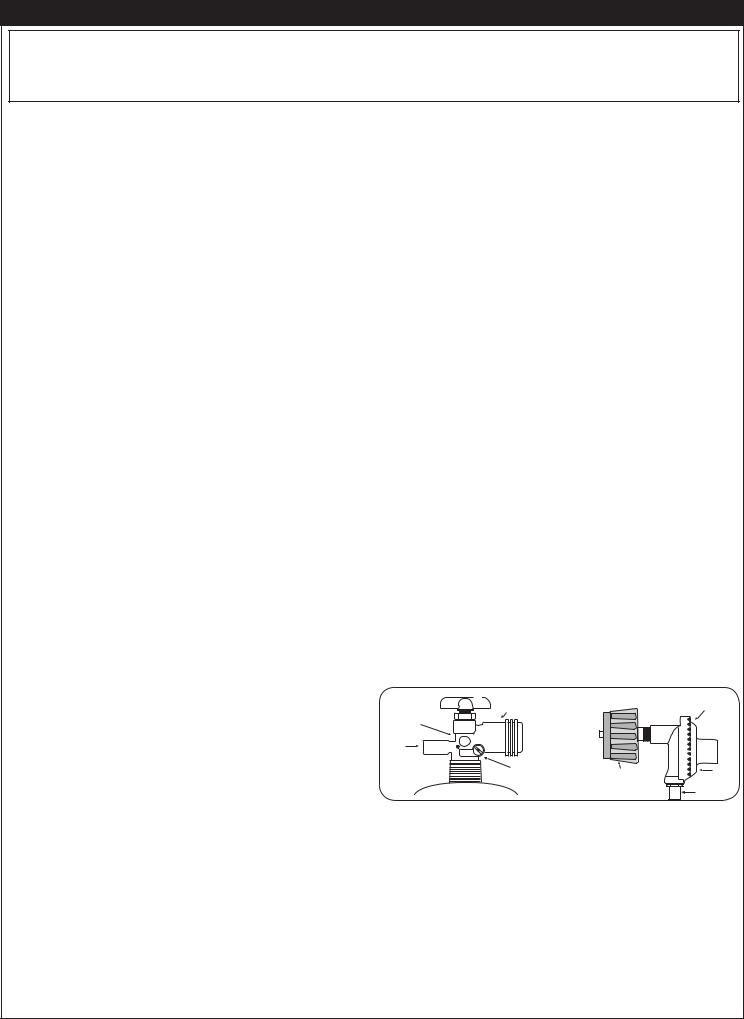
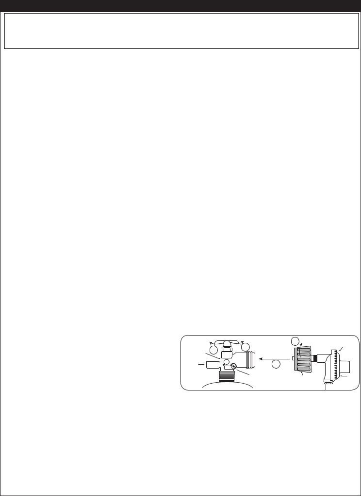
QUICK COUPLER OPERATION
To connect the regulator/hose assembly to the propanegas cylinder valve fitting: Press the hand nut on the regulator over the Acme thread fitting on the cylinder valve.Turn the hand nut clockwise to engage the threads and tighten until snug.
|
Fig. 7-1 Type I Acme thread quick coupler |
|
||
QCC |
Hand wheel |
Brass Acme |
|
Regulator |
|
|
|||
Type 1 |
|
thread fitting |
|
|
|
|
|
||
valve |
|
|
|
|
Pressure |
U L |
|
|
|
relief |
|
|
|
|
valve |
|
Liquid level |
|
|
|
|
Hand nut with Acme |
Vent |
|
|
|
indicator |
||
|
|
(optional) |
thread |
Hose |
|
|
|
|
|
7
UTILISATION SÛRE ET ENTRETIEN DES CYLINDRES DE GAZ DE PROPANE
IMPORTANT POUR VOTRE SÛRETÉ
LISEZ ET SUIVEZ TOUS LES AVERTISSEMENTS ÉQUIPÉS DE VOTRE CYLINDRE DE GAZ DE PROPANE.
En actionnant cet appareil avec un cylindre de gaz de propane ON DOIT observer ces instructions et avertissements.
LE MANQUE DE FAIRE AINSI PEUT AVOIR COMME CONSÉQUENCE UNE INCENDIE OU UNE EXPLOSION SÉRIEUSE.
CYLINDRE ET CONDITIONS ET CARACTÉRISTIQUES DE CONNECTEUR
a.Des cylindres et les valves de gaz de propane doivent être maintenus en bon état et doivent être remplacés s’il y a des dommages évidents au cylindre ou à la valve.
b.Ce gril, une fois utilisé avec un cylindre, devrait être relié à un gallon de la norme 5 (20lb.) cylindre de gaz de propane équipé d’un OPD (remplissez au-dessus du niveau le dispositif d’empêchement). L’OPD a été exigé sur tous les cylindres vendus depuis octobre 1.1998 pour empêcher le remplissage excessif.
c.Les dimensions de cylindre devraient être approximativement 12"(30.5cm) de diamètre et 18" (45.7cm) hauts. Des cylindres doivent être construits et marqués selon les caractéristiques pour des cylindres de gaz de propane du département des ETATS-UNIS du transport (D.O.T.) ou le niveau national du Canada, du CAN/CSA-B339, des cylindres, des sphères et des tubes pour le transport des marchandises dangereuses.
d.Le cylindre doit inclure un collier pour protéger la valve de cylindre et le circuit d’alimentation de cylindre doit être assuré le retrait de vapeur.
e.L'ensemblemontagerégulateurdu eurt ledetuyaupressionde pressionet le flexible(Fig.8(Fig-1) fourni. 8-1) avecfournicetavecappareilcet appareilde gazauàgazl'extérieuren plein(certainsair (modèlesmodèlesau LPpropaneseulement)seulement)doitdoitêtreêtreutiliséutilisé. As. ssembléesemblagesd'origineauxet etrégulateurrégulateurde prdepressionet le tuyaude remplacementde etntledoiventtuyau doiventêtre ceuxêtrespécificellesésquiparsontle fabricantspécifiéespourparle raccordementle fabricant pourd'unla connexiondispositif deaveccylindreun dispositifde liaisondeidentificonnexionée commecylindrede typeidentifiI parée commele 21.58-de2005/CGAtype I parANSIl'ANSIZ 1Z.621à .200558-2005/CGA(voir liste des1,6 àpièces2005 (voipour listees informationsdes pièce de commande)..
f.La valve de cylindre de gaz de propane doit être équipée d’un dispositif d’accouplement de raccordement de cylindre, décrit comme type I dans la norme définie dans le e. de paragraphe ci-dessus. Ce dispositif est généralement décrit comme coupleur rapide de fil de point culminant.
g.Si votre cylindre de gaz de propane vient avec une prise de la poussière, placez le bouchon anti-poussière sur la sortie de valve de cylindre toutes les fois que le cylindre n’est pas en service.
OPÉRATION DE COUPLEUR RAPIDE
Pour relier le regulator/hose à l’ajustage de précision de valve de cylindre de gaz de propane: Serrez l’écrou de main sur le régulateur au-dessus de l’ajustage de précision de fi l de point culminant sur la valve de cylindre. Tournez l’écrou de
main dans le sens des aiguilles d’une montre pour engager les fi ls et pour serrer jusqu’à ce que douillettement. L’utilisation des pinces ou de la clé ne devrait pas être nécessaire. Seulement le propane marqué par cylindres doit être employé.
Pour débrancher: Tournez l’écrou de main dans le sens contraire des aiguilles d’une montre jusqu’à isolé (fig. 8-1).
Important: Avant d’employer le gril, et ensuite chaque fois que le cylindre est enlevé et rattaché, examinez tous les raccordements pour déceler les fuites. Arrêtez les valves de gril et ouvrez la valve principale de cylindre, puis vérifi ez les raccordements avec de l’eau savonneux. Réparez toutes les fuites avant d’allumer le gril.
ATTENTION: Tournez toujours la valve principale de cylindre de propane au loin après chaque utilisation, et avant de déplacer le gril et le cylindre, ou débrancher l’accouplement. Cette valve doit rester fermée et le cylindre a débranché alors que l’appareil n’est pas en service, quoique l’écoulement de gaz soit arrêté par un dispositif de sûreté quand le coupleur est débranché.
Inspectez soigneusement l’ensemble de tuyau chaque fois avant que le gaz soit allumé. Un tuyau criqué ou frangé devrait être remplacé immédiatement.
Si l'appareil est stocké à l'intérieur, le cylindre doit être disconnected et a enlevé. Des cylindres Disconnected doivent être stockés dehors, hors de la portée des enfants, avec les prises de valve filetées étroitement installées, et ne doivent pas être stockés dans un bâtiment, le garage, ou n'importe quel autre secteur inclus.
POUR VOTRE SÛRETÉ
a.Ne stockez pas un cylindre de gaz disponible de propane dessous ou ne vous approchez pas de cet appareil.
b.Ne remplissez jamais cylindre au delà de 80 pour cent de plein.
c.SI L’INFORMATION DANS “A” ET “B” N’EST PAS SUIVIE EXACTEMENT, UN FEU CAUSANT LA MORT OU DES DOMMAGES SÉRIEUX PEUT SE PRODUIRE.
Fig. 8-1 type coupleur rapide de fil de point culminant d’I
Volant de commande |
Ajustage de précision |
3 |
|||
QCC |
|
en laiton de fil de |
|||
4 |
point culminant |
|
|
||
Type 1 |
|
|
|||
1 |
|
|
|
||
Valve |
|
|
|
|
|
Valve |
U L |
2 |
|
|
|
|
|
|
|||
de |
|
Indicateur |
|
|
|
décompression |
|
|
|||
de niveau |
Écrou de main avec le |
||||
|
|
||||
|
|
de liquide |
|||
|
|
fil de point culminant. |
|||
|
|
(facultatif) |
|||
|
|
|
|
||
Régulateur
Passage
 Tuyau
Tuyau
8

SPECIFICATIONS AND DIMENSIONS
Firetable Style |
BTUs |
Dimensions |
Weight / Pieces |
||
Nat. |
L.P. |
||||
|
|
|
|||
Inverted Firetable (629 & 630) |
60,000 |
50,000 |
48" dia. x 23" h |
450 / 500 lbs / 3 pcs |
|
Inverted Dining Firetable (675 & 676) |
60,000 |
50,000 |
60" dia. x 29" h |
550 / 600 lbs / 3 pcs |
|
Amphora Firetable (610 & 611) |
60,000 |
50,000 |
48" dia. x 23" h |
450 / 500 lbs / 3 pcs |
|
Chat Height Octagon Firetable (625 & 626) |
60,000 |
50,000 |
54" dia. x 24" h |
750 / 700 lbs / 3 pcs |
|
Cosmopolitan Round Firetable (645) |
60,000 |
50,000 |
48" dia. x 24" h |
250 lbs / 2 pcs |
|
Fiesta Firetable (770) |
60,000 |
50,000 |
54" dia. x 25" h |
350 lbs / 4 pcs |
|
Fiesta Dining Firetable (775) |
60,000 |
50,000 |
54" dia. x 28" h |
350 lbs / 4 pcs |
|
Contempo Round Firetable (782) |
60,000 |
50,000 |
47" dia. x 15 1/2" h |
400 lbs / 1 pc |
|
Cosmopolitan Square Firetable (640) |
60,000 |
50,000 |
36" w x 36" d x 24" h |
250 lbs / 2 pcs |
|
Nest Square / Voro Firetable (711 & 725) |
60,000 |
50,000 |
36" w x 36" d x 24" h |
290 / 250 lbs / 2 pcs |
|
Cosmopolitan Square Dining Firetable (642) |
60,000 |
50,000 |
60" w x 60" d x 29" h |
500 lbs / 2 pcs |
|
Cosmopolitan Rectangle Firetable (635) |
60,000 |
50,000 |
54" w x 36" d x 24" h |
350 lbs / 2 pcs |
|
Nest Rectangle Firetable (712) |
60,000 |
50,000 |
48" w x 28" d x 24" h |
310 lbs / 2 pcs |
|
Rectangular Firetable (650) |
60,000 |
50,000 |
48" w x 27" d x 23" h |
350 lbs / 1 pc |
|
Contempo Rectangle Firetable (783) |
60,000 |
50,000 |
52" w x 36" d x 15 1/2" h |
400 lbs / 1 pc |
|
Table 1 - Product Dimensions |
|
||||
Diameter |
|
|
|
||
|
|
|
Depth |
Width |
|
|
|
|
|
||
Height |
|
|
|
Height |
|
|
|
|
|
||
|
|
9 |
|
|
|
 Loading...