

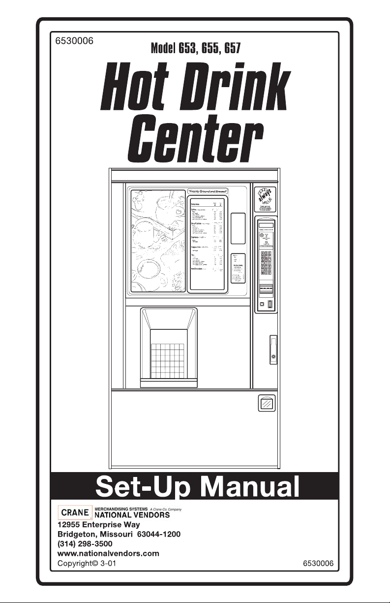
Page 1
Page 2

This machine has been engineered to our own rigid safety and performance standards. It
has been designed to comply with sanitation and health guidelines recommended by the
Automatic Merchandising Health-Industry Council (AMHIC) and it conforms with all other
NAMA safety recommendations.
This machine has been manufactured in accordance with the safety standards of both
Underwriter’s Laboratories and the Canadian Standards Association. To maintain this
degree of safety and to continue to achieve the level of performance built into this machine,
it is important that installation and maintenance be performed so as to not alter the original
construction or wiring and that replacement parts are as specified in the Parts Manual.
Your investment in this equipment will be pr otected by using the Programming Guide, this
Set-Up Guide, and the Parts Manual in your operation, service and maintenance work. By
following prescribed procedures, machine performance and safety will be pr eser ved.
Page 3

Hot Drink Center Set- Up Manual
Table of Contents
SPECIFICATIONS .............................................................................................. 1
MAJOR PARTS................................................................................................... 4
CONTROLS AND INDICATORS...................................................................... 8
INITIAL SET-UP............................................................................................... 15
I. Location Preparation................................................................................ 15
Water Requirements .............................................................................16
II. Positioning the Merchandiser.................................................................. 17
III. Connecting Everything............................................................................ 17
Connect the Merchandiser to the Water Supply: ..............................17
Connect the Merchandiser to the Electrical Power Supply: .............17
IV. Final Mechanical Preparation.................................................................. 17
Level the Merchandiser: ...................................................................17
Mount the Base Plate: .......................................................................18
Set Up the Menu Assembly ..............................................................19
Install the Water Filter Cartridge: .....................................................21
Load the Optional Filter Paper: ........................................................24
Install the Optional Coin Box Lock ..................................................26
Load the Coin Mechanism ................................................................26
Fill the Tank: ............................................................................ ..... ...27
Fill the Canisters: ..................................................... ..... ...... ..............27
Load Cups: ........................................................................................28
Tell the Machine About the Cup Size(s): .........................................29
Test the Machine: .............................................................................30
ADJUSTMENTS AND MINOR MAINTENANCE ......................................... 31
I. Water Valve Adjustment......................................................................... 31
II. Cup Mechanism Adjustment................................................................... 32
III. Grinder Adjustment................................................................................. 33
IV. Disengaging the Grinder.......................................................................... 34
V. Canister Installation................................................................................. 34
SANITATION.................................................................................................... 35
I. Basics....................................................................................................... 35
II. Clean the Hot Water Tank....................................................................... 37
III. Sanitation Procedures .......................... ................................. ...... ............. 37
Food-Contact Parts ...............................................................................37
Non Food-Contact Parts .......................................................................38
IV. Overall Cleaning.................................................. .................................. .. 39
V. Preventive Maintenance Cleaning........................................................... 39
APPENDIX A. THE FREE VEND KEYSWITCH OPTION........................ A-1
APPENDIX B. THE INFRARED MUG/CUP SENSOR ............................... B-1
APPENDIX C. DEX/UCS INTERFACE OPERATION................................ C-1
6530006 i
March, 2001
Page 4

Hot Drink Center Set-Up Manual
APPENDIX D. MODIFY CANISTER TO VEND 12 OZ. CUPS................ D-1
ii 6530006
March, 2001
Page 5
Hot Drink Center Set- Up Manual
SPECIFICATIONS
SPECIFICATIONS COMMON TO ALL MACHINES
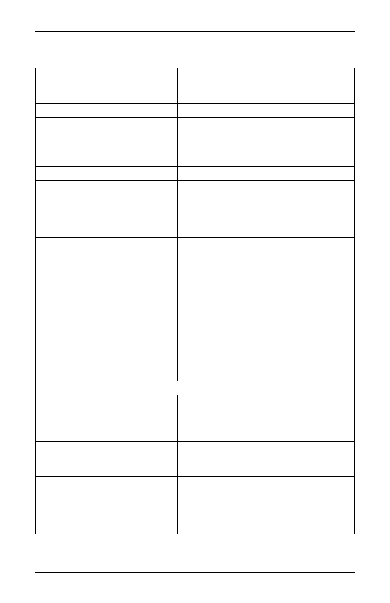
DIMENSIONS 72" (183 cm) high
38.12" (97 cm) wide
28.5" (72 cm) deep
WEIGHT 570 lbs (258.5 kg)
WATER REQUIREMENTS Minimum: 20 psi (137.8 kPa)
Maximum: 80 psi (551.2 kPa)
AMBIENT TEMPERATURE Minimum: 41× F (5× C)
Maximum: 90× F (32× C)
OPERATING ENVIRONMENT For indoor use only
CUP CAPACITIES
(APPROXIMATE)
CANISTER CAPACITIES
(APPROXIMATE)
MODEL 633 FRESH BREW Up to nine selections of fresh brew regular and
MODEL 635 FREEZE DRIED Up to nine selections of freeze dried regular cof -
MODEL 637 FRESH BREW
WITH
BEAN GRINDER
7 oz cups (squat) - 1150
8.25 oz cups - 1050
9 oz cups (squat) - 1100
10 oz cups - 1000
12 oz cups - 940
Regular coffee be ans - 14 lbs
Ground coffee - 13 lbs
Freeze dry coffee - 2 lbs
Decaf coffee beans - 9.5 lbs
Ground decaf coffee - 9 lbs
Freeze dry decaf - 2 lbs
Chocolate - 10 lbs
Soup - 6.7 lbs
Sugar - 11 lbs
Lightener - 4.5 lbs
Sugar substitute - 4 lbs
Tea (freeze dry) - 1.5 lbs
6th and 7th products (freeze dry) - 6 lbs each
PRODUCT OPTIONS
decaf coffee, freeze dried regular and decaf cof
fee, fresh brew and freeze dried tea, soup, chocolate, cappuccino, espresso, and caffè latte.
fee, decaf coffee, tea, soup, chocolate, cappuccino, espresso, and caffè latte.
Up to nine s elect ions o f fres h gr ound a nd bre wed
regular and decaf coffee, freeze dried regular and
decaf coffee, fresh brew and freeze dried tea,
soup, chocolate, cappuccino, espresso, and caffè
latte.
-
6530006 1
March, 2001
Page 6
Hot Drink Center Set-Up Manual
SPECIFICATIONS COMMON TO ALL MACHINES (Continued)
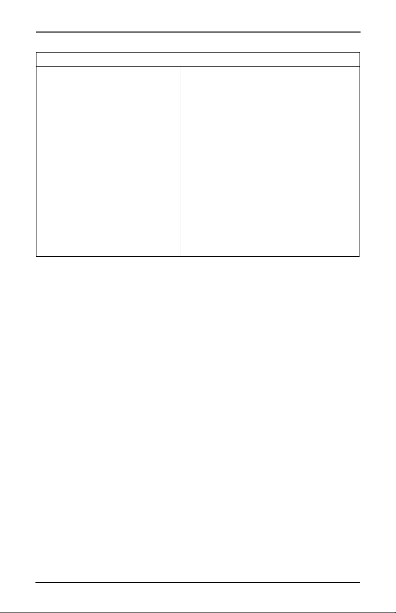
OPTIONS AND ACCESSORIES
OPTIONS Coffee brewer filter paper (5000 vends per roll)
Coin box lock
Base grille kit
Automatic delivery door
Flex Ace door lock and key
Van Door lock and key
Sugar substitute kit
6th product kit
Cup/mug electronic sensor (cup hold switch kit)
Snap-on ingredient canister
extension sleeves (4 tall)
Everpure water filter system
CUNO water filter system
Debit card validator
Free vend keyswitch
Data printer kit
Ingredient rinse tray
2 6530006
March, 2001
Page 7
Hot Drink Center Set-Up Manual
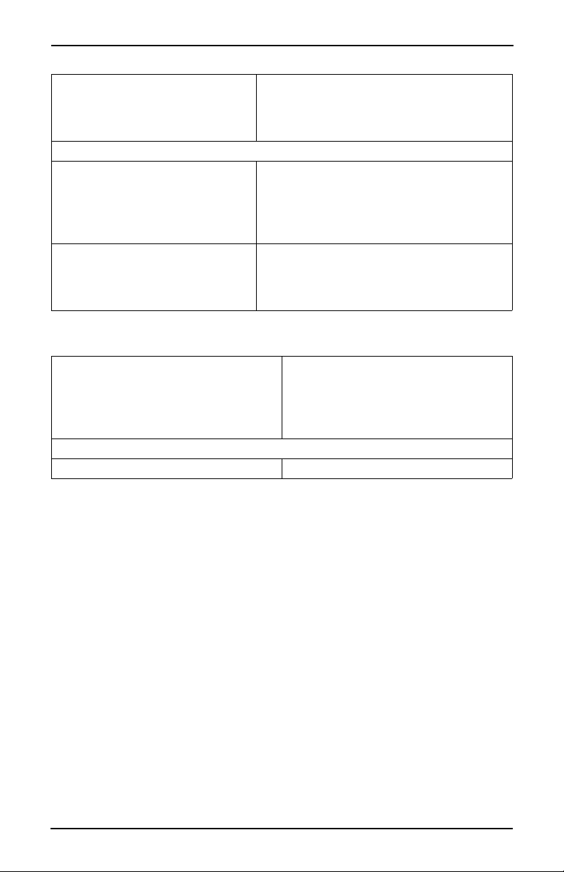
SPECIFICATIONS UNIQUE TO 115 VOLT MACHINES
ELECTRICAL 115 Volts AC
60 Hertz
12 Amps
Single phase
OPTIONS AND ACCESSORIES
COIN MECHANISM MARS TRC-6000
COINTRON 3000
MARS TRC-6010XV (24 V)
Maka/Conlux Model USPX-004 (24 V)
Coin Acceptors Model 9302-LF (24 V)
BILL VALIDATORS MARS VFM1 pulse
MARS VFM3 serial
MAKA pulse
COINCO
SPECIFICATIONS UNIQUE TO 220 - 240 VOLT MACHINES
ELECTRICAL 220-240 Volts AC
50 Hertz
10 Amps
2 kW
Single phase
OPTIONS AND ACCESSORIES
COIN MECHANISM Executive coin mechanism interface
6530006 3
March, 2001
Page 8
Hot Drink Center Set-Up Manual
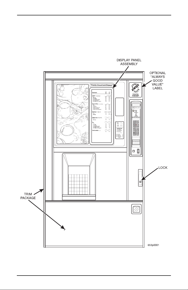
MAJOR PARTS
The diagrams on the following pages will acquaint you with the major parts of the Hot Drink Center. For more detailed information, please consult your PARTS MANUAL. If you do not have a PARTS MANUAL, contact National Vendors Parts Department.
Door Assembly - Exterior
4 6530006
March, 2001
Page 9
Hot Drink Center Set-Up Manual
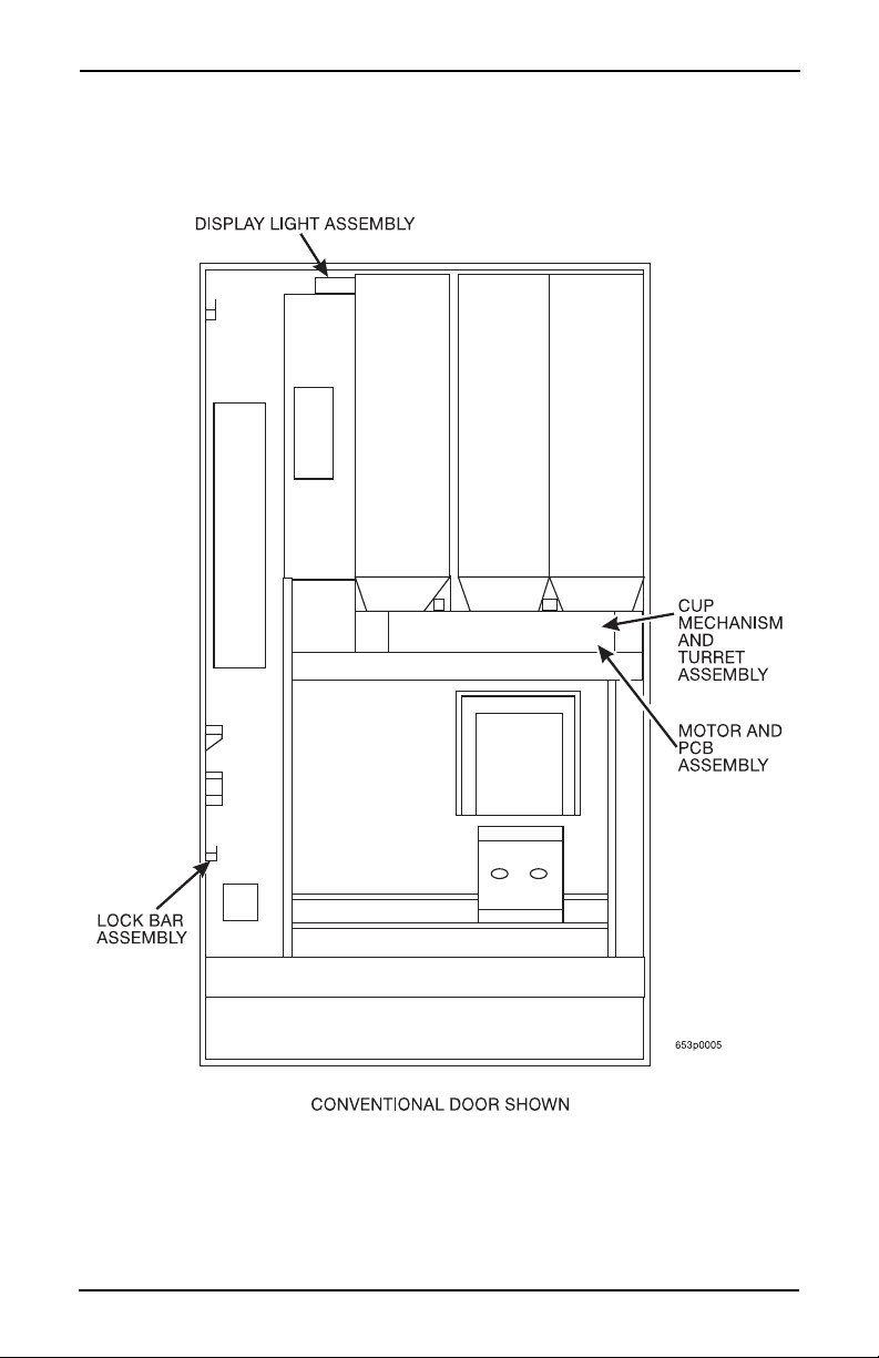
Door Assembly - Interior
6530006 5
March, 2001
Page 10
Hot Drink Center Set-Up Manual
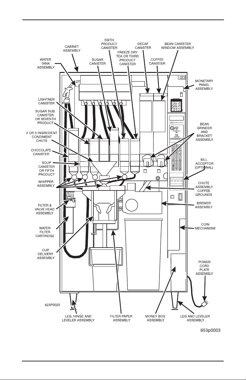
Cabinet Assembly Interior - Part 1
6 6530006
March, 2001
Page 11
Hot Drink Center Set-Up Manual
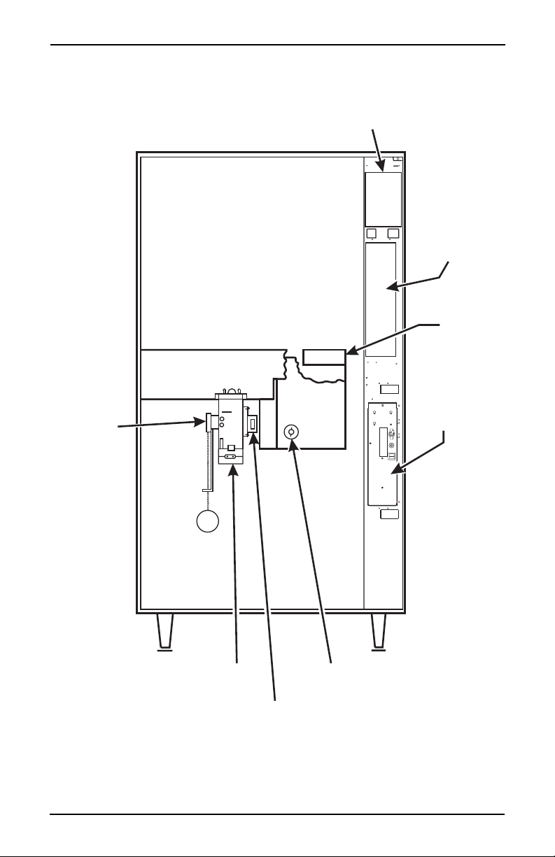
MAIN CONTROLLER
R
BRACKET ASSEMBLY
O
PCB ASSEMBLY
INTERFACE
BOARD
˜
AIR
COMPRESSO
ASSEMBLY
POWER
VERFLOW
SWITCH
ASSEMBLY
˜
PANEL
ASSEMBLY
OPTIONAL INFRARED
CUP/MUG SENSOR
EXHAUST FAN
BREWER DRIVE
ASSEMBLY
Cabinet Assembly Interior - Part 2
6530006 7
March, 2001
Page 12

Hot Drink Center Set-Up Manual
S
CONTROLS AND INDICATORS
POWER PANE L. You may have one of three power panels, depending upon
where you live. The controls are fundamentally the same, however.
Circuit Breakers and Fuses. Circuit breakers and fuses protect the merchan-
diser against failures in the power supply or any of the electrical components. If
a circuit breaker trips and canno t be res et, or if a fuse repeatedly blows, contact a
field service representative.
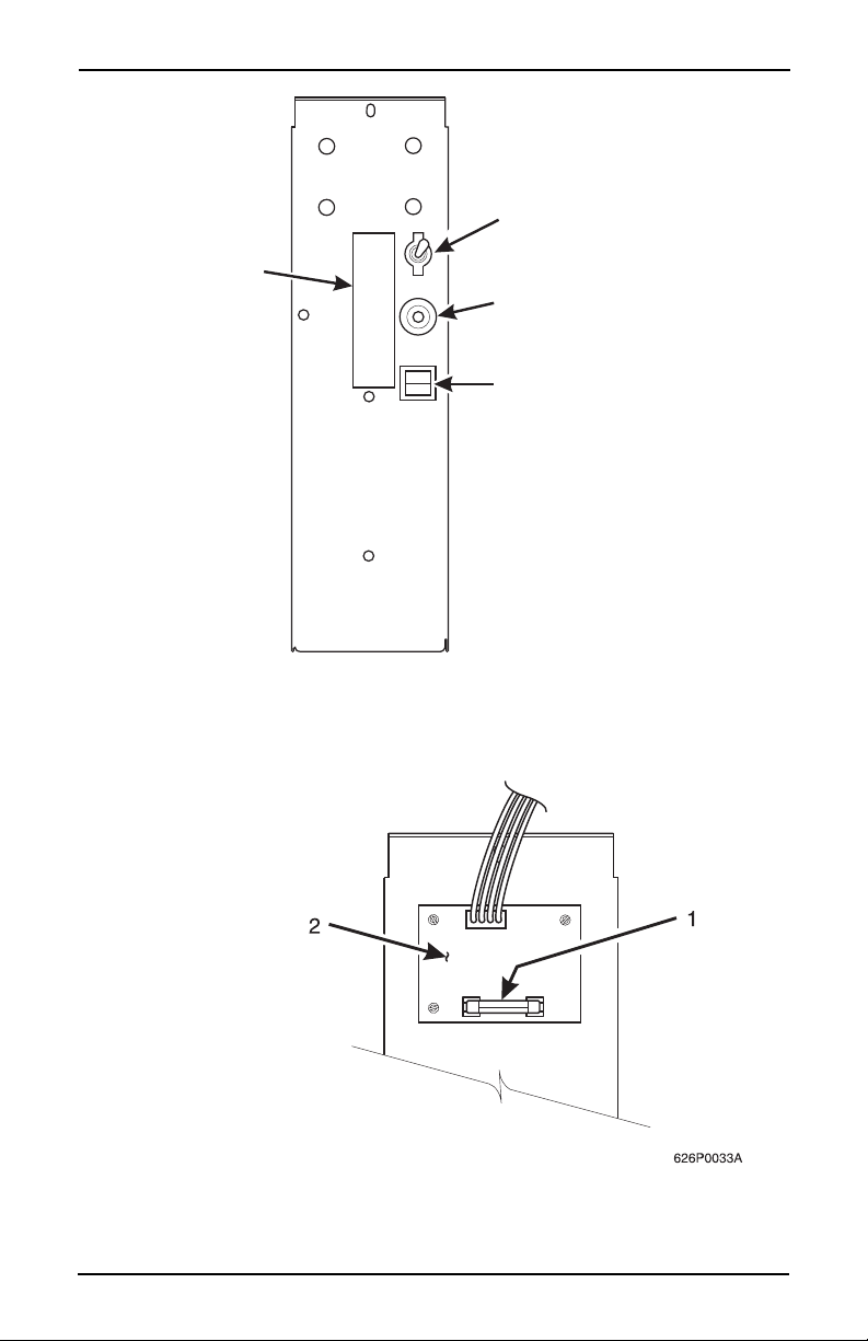
Back Side of U.S./ Canada Power Control Panel. The circuit board mounted
on the rear of the U.S. and Canadian power co ntrol panel is a dc power suppl y for
the coin mechanism. A fuse protects the board circuitry in the event of a coin
mechanism solenoid failure. If the coin mechanism is not working, check this
fuse. If the fuse is blown, a bad coin mechanism solenoid could be at fault.
Main Power Switch. This is the main ON/OFF switch for the merchandiser.
WARNING
T o protect against electrical shocks and possible damage to the
machine, turn this switch OFF when performing any mainte
nance on the merchandiser.
-
I
LABEL
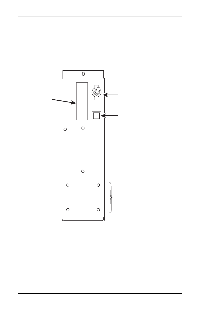
Power Control Panel (France/Germany/ Spain)
8 6530006
O
MAIN
POWER
SWITCH
ELECTRONIC
BREAKER
626P0005
March, 2001
Page 13
LABEL
Hot Drink Center Set-Up Manual
MAIN
ON
OFF
Power Control Panel (U.S./Canada)
POWER
SWITCH
MAIN
CIRCUIT
BREAKER
LOW VOLTAGE
CIRCUIT BREAKER
626P0006
Back Side of U.S./Canada Power Panel
6530006 9
March, 2001
Page 14
Hot Drink Center Set-Up Manual
ON
MAIN POWER
ELECTRONICS
CIRCUIT BREAKER
LABEL
OFF
SWITCH
MOUNTING STUDS
FOR MEXICO ONLY
626P0035a
Power Control Panel (U.K./Mexico)
10 6530006
March, 2001
Page 15
Hot Drink Center Set-Up Manual
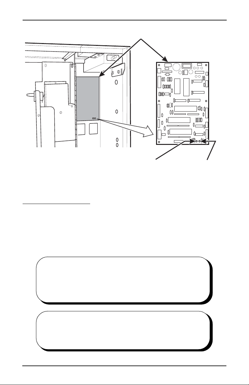
MAIN CONTROLLER
T
PCB ASSEMBLY
LED1 LED2
POWER ON
(LED 1)
FLASHING
HEARTBEA
(LED 2)
Main Controller PCB Display
Main Controller PCB Display. This display consists of two light emitting diodes (LED)
mounted on the controller PCB.
POWER ON
(LED 1)
HEARTBEAT
(LED 2)
When lit, this red LED indicates electrical powe r is applied to the controller
PCB.
When flashing, this red LED indicates that the controller PCB is active, and
the software is operating.
NORMAL CONDITIONS:
When the merchandiser is operating normally, you should see a
steady red POWER ON indicator. The red HEARTBEAT indi cator should be flashing with a balanced on/off pattern (on for
the same length of time that it is off).
ERROR CONDITIONS:
If an error is present, the red HEARTBEAT indicator will flash
with an unbalanced on/off pattern (on longer than it is off). The
error(s) can be viewed under the DIAGNOSTICS mode.
6530006 11
March, 2001
Page 16
Hot Drink Center Set-Up Manual
Monetary Panel
12 6530006
March, 2001
Page 17
Hot Drink Center Set-Up Manual
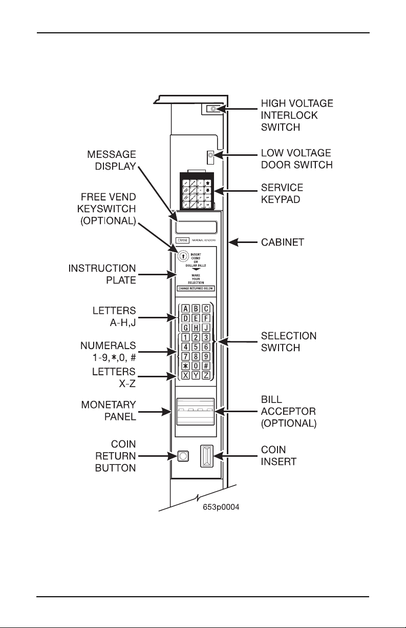
High V oltage In terlock Switch (U.S./ Canada). When the cabinet door is open ,
this switch turns off the optional fan and bean light (if so equipped) and turns on
the service light.
High V o ltage Interlock Switch (International). When the cabinet d oor is o pen,
this switch turns off all high voltage to the cabinet. Pulling the switch out
restores high voltage for maintenance purposes.
Low Voltage Door Switch. Informs the controller software of the main door
open or closed status.
Message Display. This is how the merchandiser communicates with the outside
world. Customers can see messages about ho w much money they have put into
the merchandiser. The message display also tells customers when a selection is
sold out and when vendi ng is free, in hibit ed, or discoun ted. The mes sage displ ay
shows you what you are doing when you program the merchandiser, and can
show you what is wrong if there is a failure.
Free Vend Keyswitch. This allows someone (other than maintenance people) to
set the merchandiser to free vend without opening the door.
Selection Switch Panel. The customer uses these switches to make selections.
Also, maintenance people may use this switch panel during programming and
other support modes.
Coin Return Button. Pressing this button returns any coins that have been paid
into the merchandiser prior to a vend.
Bill Acceptor (Optional). Accepts bills in various denominations, depending
upon the type of bill validator, and how the machine is configured.
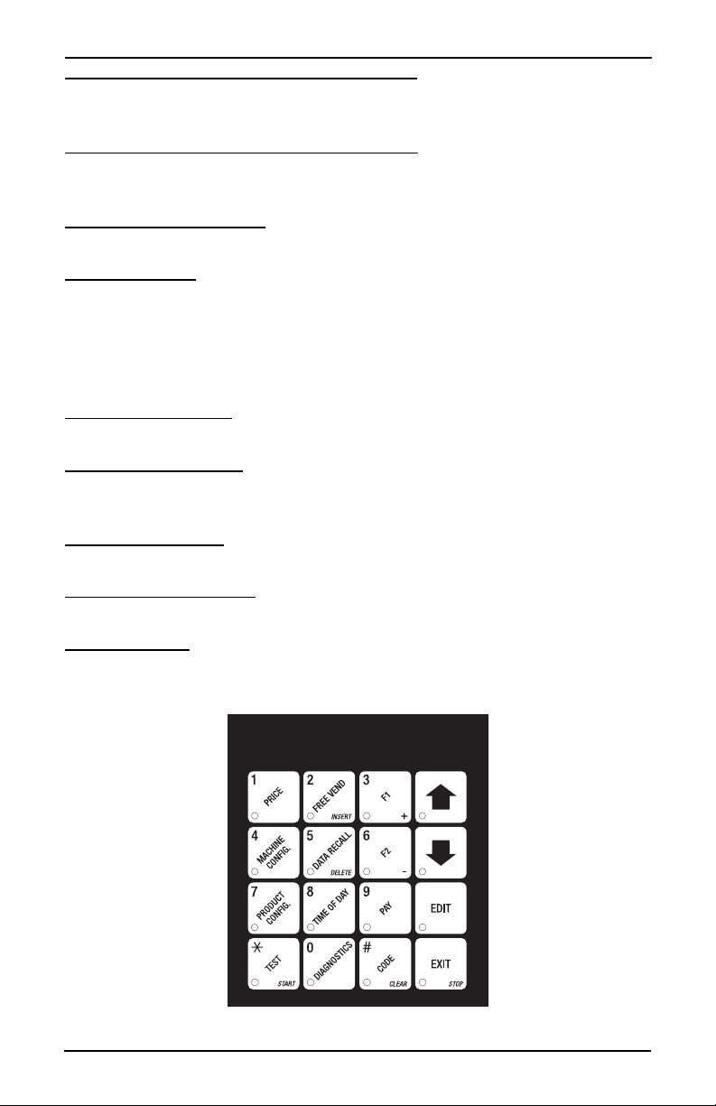
Service Keypad. The service keypad is located at the top of the monetary pan el.
It gives service personnel the means to program, retrieve data from, and view
diagnostic information about, the merchandiser.
Service Keypad
6530006 13
March, 2001
Page 18
Hot Drink Center Set-Up Manual
Y
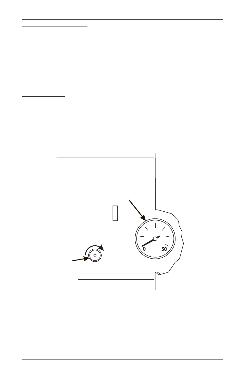
Pressure Adjust Control. This control determines the system pressure provided
by the air compressor. Adjust the pressure as follows:
a. With the compressor running, pinch the brewer inlet air tube.
b. Adjust the pressure to read 10 - 12 psi on the gauge.
This will produce a pressure of 3 - 6 psi using regular coffee and 8¼ oz cups. No
further air pressure adjustments should be necessary.
Pressure Gauge. This indicator shows the amount of air pressure in the system.
PRESSURE
ADJUST
CONTROL
PRESSURE
GAUGE
INCREASE
INGREDIENTS SHELF
MONETAR
PANEL
Press ure Control and Indicator
14 6530006
March, 2001
Page 19
Hot Drink Center Set-Up Manual
INITIAL SET-UP
I. Location Preparation
After your machine is unpacked and placed near its permanent location , you need
to make sure you have the proper electrical and water service.
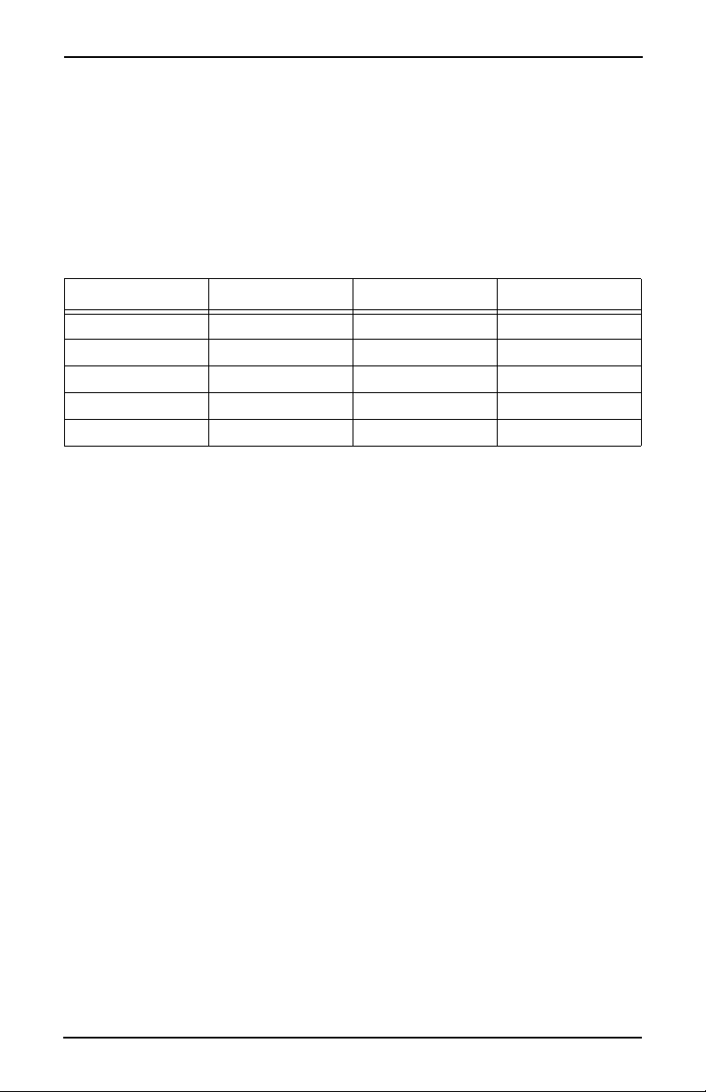
This merchandiser needs electrical power as shown in the following table.
NOTE: Each merchandiser should have its own electrical circuit.
Power Requirements
Country Volts Frequency (Hz) Current (Amps)
Canada 115 60 15
France 230 50 10
Germany 230 50 10
United Kingdom 230 50 10
United States 115 60 15
This merchandiser is supplied with a service cord for the country of use and is
terminated in a grounding type plug. The wall receptacle used for this merchan
diser must be prop erly polarized , grounded , and of the correct voltage. Operating
the merchandiser from a source of low voltage will VOID YOUR WARRANTY .
Each merchandiser should have its own electrical circuit and that circuit should
be protected with a circuit breaker or fuse conforming to local regulations.
-
Voltage Check - Place the leads of a voltmeter across the LINE (LIVE) and
NEUTRAL terminals of the wall receptacle. The voltmeter should indicate
110-130 volts ac for 120 volt, 60 Hz locations, or 220-240 volts ac for 230
volt, 50 Hz locations.
Polarity Check - Place the leads of a voltmeter across the LINE ( LIVE) and
GROUND terminals of the wall receptacle. The voltmeter should indicate
110-130 volts ac for 120 volt, 60 Hz locations, or 220-240 volts ac for 230
volt, 50 Hz locations.
Noise Potential Check - Place the leads of a voltmeter across the NEUTRAL and GROUND terminals of the wall receptacle. The voltmeter
should indicate 0 volts ac. A measurement greater than 1.5-2.0 volts ac
could result in problems for the mercha ndiser's electronic ci rcuitry caused by
electrical noise.
Any deviation from these requirements could result in unreliable performance
from your merchandiser.
6530006 15
March, 2001
Page 20

Hot Drink Center Set-Up Manual
Water Requirements
The best type of water for coffee brewing is normal hard (tap) water. If your
location has chemically softened water, you should do one of the following
things:
• Have a non-softened supply line run to the merchandiser
• Contact your local water filter supplier for information and suggestions
Well water can also be used in the Hot Drink Center. However,
you should have it checked for levels of carbonates and alka
lies. Contact your water filter supplier if these values are rela-
tively high.
What is the Water Pressure at Your Location?
It should be no less than: 10 psi ( 69.0 K Pa) at 1/2 gall on/minute
And no more than: 80 psi (522.0 KPa) at 1/2 gallon/minute
If you're not sure about the pressure and flow rate, check with your water company.
What to do With the Water Supply Line:
• Locate the supply line at the rear of your merchandiser.
• Equip the line with a shut-off valve.
-
Flush the water supply line before connecting it to the merchandiser. A minimum of five gallons is usually required before connecting the merchandiser to
the supply line. DO NOT flush the merchandiser water system. If you do, you
might introduce water line contaminants into the merchandiser.
16 6530006
March, 2001
Page 21

Hot Drink Center Set-Up Manual
II. Positioning the Mercha ndiser
You can position this merchandiser anywhere in a bank of machines. It can even
be placed on the end flush against a side wall. Be sure yo u leave enough roo m in
front of the merchandiser for the door to move freely.
BE SURE THE REAR OF THE MERCHANDISER IS AT LEAST 6
INCHES (15 cm) AWAY FROM THE WALL. THIS WILL ALLOW
WARM MOIST AIR TO BE VENTED OUT OF THE MACHINE'S INTE
RIOR.
WARNING
THIS MACHINE IS ONLY RATED FOR INSTALLATION IN AN
INDOOR LOCATION.
III. Connecting Everything
1. Connect the Merchandiser to the Water Supply:
a. You will need the following:
• A coil of copper tubing with outside diameter of 3/8 inch (9.5 mm) or
greater. The appropriate plastic tubing may be substituted. The tubing
must be long enough to reach from the water sour ce to you r machin e with
enough left over to form a loop about 2 feet (60 cm) in diameter. This
will allow you to move the machine without straining the water line.
• A 3/8 inch (9.5 mm) flare fitting.
-
b. Connect the merchandiser to your water supply.
2. Connect the Merchandiser to the Electrical Power Supply:
Power inside the merchandiser is controlled by the main power switch, located
on the power panel.
a. Make sure the main power switch is OFF.
b. Connect the merchandiser’s power cord to your wall outlet.
IV. Final Mechanical Preparation
1. Level the Merchandiser:
a. Using a spirit level, adjust the front and rear leg levelers until the
machine is level from side to side and back to front.
6530006 17
March, 2001
Page 22
Hot Drink Center Set-Up Manual
a
o
.
.
e
B
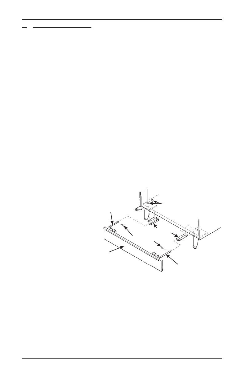
2. Mount the Base Plate: WARNING
DO NOT MOVE THE CABINET WHILE HEX HEAD
SCREWS AND/OR CARRIAGE BOLT S ARE LOOS
ENED. THE CABINET WOULD BECOME UNSTABLE
AND LIKELY TO TIP AND CAUSE INJURY.
a. Remove the pail(s) from the inside of the merchandiser.
b. Remove the floor liner from the inside of the merchandi ser.
c. Remove the two caps as shown.
d. Lo osen the left leg assembly carri age bolts and nuts to allow mounting
base plate bracket.
e. Secure one of the base plate brackets to the leg assembly using the tw
carriage bolt. Tighten the carriage bolts and nuts.
f. Loosen the right leg assembly hex head screws to allow mounting the
other base plate bracket.
g. Secure the other base plate bracket to the right leg assembly using the
two hex head screws. Tighten the hex head screws.
h. Insert the short arms of the slides into the hinged tabs of the base plate
Position the slide so the notch near the short arm is on the bottom side
i. Insert the long
arms of the
slides into the
base plate
SLIDE - L.H.
CAPS
brackets.
j. Insert and
secure a cotter
pin throug h
BASE PLATE BRACKET
COTTER PIN
the hole in the
back of each
of the slides.
ASE PLATE
ASSEMBLY
k. Push the base
plate toward
the merchandiser cabinet.
The front tabs of the base plate brackets should seat in the notches in th
long arms of the slides.
l. Replace the caps, liner, and pail(s) removed previously.
-
SLIDE - R.H.
18 6530006
March, 2001
Page 23
Hot Drink Center Set-Up Manual
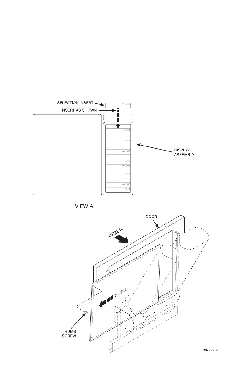
3. Set Up the Menu Assembly
Glass door:
a. Swivel the cup turrets away from the door.
b. Remove the thumb screws as shown, and slide out the menu assembly.
c. Install selection inserts as shown.
d. Reinstall the menu assembly in the reverse order of assembly.
6530006 19
March, 2001
Page 24

Hot Drink Center Set-Up Manual
Solid door:
a. From the inside of the door, remove 2 menu retaining knurl screws.
b. From the ou tside of the door, slide the clear menu window up to acess
the menu strips and price and cup size labels.
c. Set up the menu as appropriate for your machine.
d. Reinstall the menu assembly in the reverse order of assembly.
20 6530006
March, 2001
Page 25

Hot Drink Center Set-Up Manual
1
C
4. Install the Water Filter Cartridge: IF YOUR MERCHANDISER HAS THE WATER FILTER
OPTION, IT CANNOT BE OPERATED WITHOUT A
PROPERLY INSTALLED WATER FILTER CAR
TRIDGE. If you do not have the water filter option, continue
with "Fill the Tank"
.
UNO BRAND ...
NOTE
Check the water filter installation record. There is a place to write
the vend number on the cartridge. The cartridge is effective for a
maximum of 64,000 7 oz. vends, 56,000 8 oz. vends, 50,000 9 oz.
vends, or 37,000 12 oz. vends. Local conditions may require more
frequent replacement.
CUNO FILTER
FILTER
LOCKING
TAB
TO INSTALL
THE FILTER:
1. INSERT NEW FILTER,
ROTATE COUNTERCLOCKWISE UNTIL
FILTER LOCKING TAB
SNAPS INTO GROOVE
AS SHOWN.
HEAD ASSEMBLY
GROOVE
-
. CLOSE THE WATER SHUT
-OFF VALVE BY TURNING
THE KNOB TO THE
HORIZONTAL POSITION
AS SHOWN.
SHUT-OFF
TO REMOVE FILTER:
WATER
KNOB
2. LIFT THE FILTER
LOCKING TAB,
ROTATE FILTER
CLOCKWISE AND
PULL DOWN AS
SHOWN.
CUNO
FILTER
FILTER
LOCKING
TAB
6530006 21
March, 2001
Page 26
Hot Drink Center Set-Up Manual
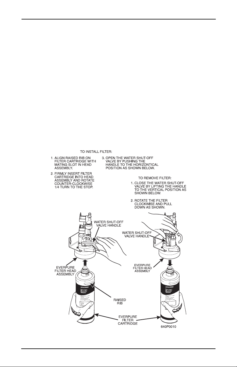
EVERPURE BRAND ...
NOTE
Check the water filter installation record. There is a place to
write the vend number on the cartridge. The cartridge is effec
tive for a maximum of 26,000 7 oz. ven ds , 22,0 00 8 o z. vend s,
20,000 9 oz. vends, or 15,000 12 oz. vends. Local conditions
may require more frequent replacement.
National Vendors recommends that you d o the fol lowing procedu re the first time
you fill the tank in your merchandiser:
a. Remove the small inner "O" ring from the filter cartridge.
b. Install the filter cartridge.
c. Turn on the water at its source, and perform the tank filling procedure.
d. Turn off the water at its source, remove the filter cartridge, and replace
the "O" ring.
e. Install the filter cartridge.
-
22 6530006
March, 2001
Page 27

Hot Drink Center Set-Up Manual
E
HYDROLIFE BRAND...
INSTALLATION:
1. Place the filter inside the canister. Be sure the o-ring is seated in the canister just below the threads.
2. Screw the canister and filter assembly onto the filter head until it comes to a stop.
3. Open the water valve on the inlet line by rotating the handle to the vertical position as s hown.
REMOVAL
4. Close the valve on the inlet line by rotating the handle into the horizontal position as s hown.
5. Relieve water pressure by performing two or three water throws (see the Programming Guide).
6. Unscrew the filter and canister assembly from the filter head. Remove the filter from the canister.
OPEN
POSITION
INSTALL
HYDROLIFE
FILTER HEAD
O-RING
REMOV
OPEN
POSITION
VALVE
CLOSED
POSITION
FILTER
CANISTER
6530006 23
March, 2001
Page 28

Hot Drink Center Set-Up Manual
H
R
TO BREWER
PAPER
PINION GEAR SHAFT
G
L
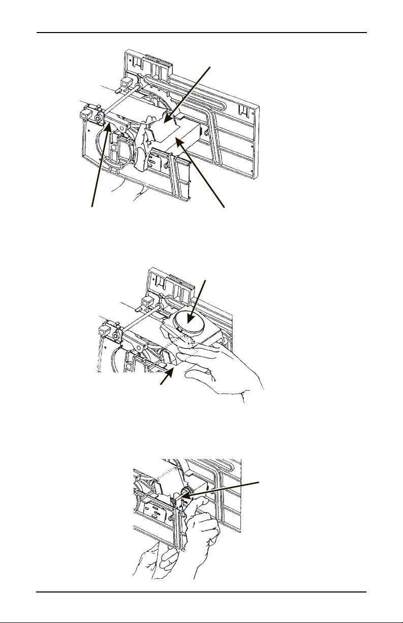
1. Load the Optional Filter Paper:
a. Be sure the main power switch is in the OFF position.
b. Remove the cup station and grounds bucket.
c. Remove the paper holder cover by turning the fastener a quarter turn to
the left.
d. Insert a roll of paper into the paper holder. Route the free end of the
paper to the brewer as shown.
e. Replace the cover on the paper holder. Secure it by turning the fastener
a quarter turn to the right.
f. Feed paper over swing arm assembly and underneath pinion gear shaft.
PAPER
OLDER
PAPER
ROLL
COVER
FASTENE
g. Feed paper through the paper guides.
h. Raise the basket housing assembly and feed paper over th e lip of the
paper mechanism housing.
GUIDES
BASKET HOUSIN
ASSEMBLY
SWING ARM
ASSEMBLY
IP OF PAPER MECHANISM HOUSING
It may be necessary to reach underneath the brewer between
PAPER MECHANISM HOUSING
NOTE
the paper mechanism housing and swing a rm as sembly to p ush
paper over the lip of the paper mechanism housing.
24 6530006
March, 2001
Page 29
Hot Drink Center Set-Up Manual
G
SWING ARM ASSEMBLY
Y
R
LIP OF PAPER MECHANISM HOUSIN
PAPER MECHANISM HOUSING
i. Reach underneath the brewer between the paper mechanism housing
and basket housing assembly and push paper into the top of the paper
mechanism housing between paper rollers.
BASKET HOUSING ASSEMBL
PAPER MECHANISM HOUSING
j. Reach underneath the brewer and pull paper roller to the right.
k. Pull paper down between the paper rollers.
l. Release the paper roller.
6530006 25
March, 2001
PAPER
ROLLE
Page 30
Hot Drink Center Set-Up Manual
2
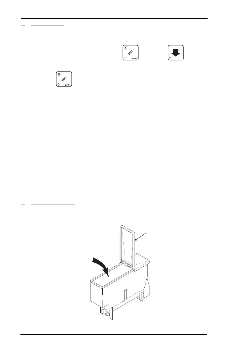
m. Place the main power switch in the ON position.
n. Test the brewer to be sure the paper feeds properly:
1. On th e maintenance k eypad, pres s , then press until
the display shows BREW TEST.
2. Press to test each brewer position:
WARNING
Keep away from the brewer mechanism while it is operating.
Coming into contact with moving parts could injure you.
BREW 'R BREW The brewer is in the BREW POSITION.
BREW 'R FLIP The brewer is in the FLIP position.
BREW 'R HOME The brewer is in the HOME position.
3. Make sure the filter paper feeds properly without jamming.
o. Replace the cup station and grounds bucket.
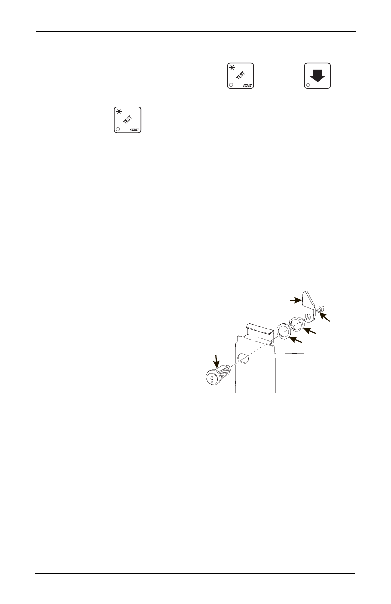
. Install the Optional Coin Box Lock
a. Install the lock cylinder,
washer, and nut in the order
shown.
b. Tighten the nut.
c. Install the lock bar as shown,
and secure with the screw.
LOCK
CYLINDER
LOCK BAR
SCREW
NUT
WASHER
3. Load the Coin Mechanism
a. Open the cabinet door and the monetary door.
b. Insert coins into their respective tubes until each tube has been filled.
c. Inspect the tubes for shingled coins and correct if necessary.
26 6530006
March, 2001
Page 31
Hot Drink Center Set-Up Manual
D
4. Fill the Tank:
a. Make sure the main power switch is ON.
b. Turn on the water at its source.
c. On the maintenance keypad, press , then press u ntil the
display shows TANK.FILL.
d. Press . Y ou should hear water running into the tank, and the dis-
play will show FILLING. The water will run until either the tank is full or
12 minutes go by, whichever happens first.
NOTE
The inlet water valve only stays open for 12 minutes at a tim e.
This is a safety feature to prevent water from running into a
leaky system and making a mess. It is possible for your tank to
take longer than 12 minutes to fill if your location has low
water pressure. To be on the safe side, check for leaks if the
water runs a long time. If you find none, every thing is normal;
you just have low water pressure.
e. When you hear the water stop running, repeat steps 3 and 4. Un der no r-
mal circumstances, nothing will happen. If water starts running and the
display shows FILLING again, your pressure is low and it is just taking a
long time to fill the tank. Repeat this step if necessary to be sure your
water tank is full.
5. Fill the Canisters:
a. Open the lid as shown, and carefully pour the appropriate product into
the canister. Repeat for all canisters in the machine.
LI
FILL
CANISTER
6530006 27
March, 2001
Page 32

Hot Drink Center Set-Up Manual
D
VIEW LOOKING DOWN
TURRET DESIGNATIONS
6. Load Cups: CAUTION
Use only cups which have been designed for use in a h ot beverage vending machine.
a. Support the cup mechanism in the upright position.
b. Push the latch forward to release the cup mechanism. Continue to s u p-
port the cup mechanism while you lower it into the loading position.
c. Remove the turret cover.
OBSERVE PROPER HYGIENE - DO NOT TOUCH THE CUPS!
d. Open the bottom of the wrapper on a stack of cups.
e. Insert the wrapped cups into the turret and pull the wrapper out.
DO NOT FILL CUPS ABOVE THE LEVEL MARKED
ON THE OUTSIDE OF THE CUP TURRETS OR
ABOVE THE “FIL L LINE” LABE L IN SID E EAC H TUR
RET, OR MO TOR JAMS WILL OCCUR.
USE ONLY THE SAME SIZ E AND BRAND OF HOT
DRINK CUPS IN EACH TURRET; DO NOT INTERMIX!
f. Replace the turret cover after the turrets have been loaded.
g. Be sure the cup mechanism is locked into the upright position.
-
CUP STACK ROTATION
OOR
1B 1A2
CUP
MECHANISM
28 6530006
March, 2001
Page 33

CABINET
DOOR
CUP MECH
MOUNTING
BRACKET
Hot Drink Center Set-Up Manual
LID
RETAINING
STRAP
LOAD CUPS
HERE
CUP TURRET
LATCH
CUPS
TOP VIEW
7. Tell the Machine About the Cup Size(s):
Your Hot Drink Center can vend two different cup sizes, so you will need to
"tell" the merchandiser the sizes of cups you have loaded into it.
a. Press , then press until the display shows CUP X OZ .
b. Press until the capacity of the regular size cups you loaded is
displayed.
6530006 29
March, 2001
Page 34

Hot Drink Center Set-Up Manual
c. Press , an d t he display shows CUP.1 X OZ.
d. Press until the capacity of the large size cups you loaded is dis-
played.
8. Test the Machine:
Your Hot Drink Center is now ready to vend coffee, just as soon as the water in
the tank reaches its operating temperature. Press
, and a reading of the
tank temperature is displayed. When the display shows 94° C (202° F), it is
ready for vending.
a. Close the door, make a selection, and enjoy your cup of coffee!
b. You will now need to do the following before your machine is ready to
start earni ng money:
• Set prices
• Set up the menu
• Establish time of day vending periods (if desired)
• Customize the drink recipes (if desired)
• Set up custom messages (if desired)
Refer to the Programming Guide for details on these and other pro cedur es.
30 6530006
March, 2001
Page 35

Hot Drink Center Set-Up Manual
ADJUSTMENTS AND MINOR MAINTENANCE
This section contains procedures not normally used during setup, but may come
in handy later on.
I. Water Valve Adjustment
W ater v alves do not us ually require ad justment, bu t in some cas es adequate wate r
volume cannot be achieved by the throw time setting alone (see the Program
ming Guide). IF ABSOLUTELY NECESSARY, adjust the valves in conjunc-
tion with setting the factory default timers during the product configuration
programming mode.
a. Using a slotted screwdriver, turn the adjustment screw clockwi se to
decrease the water flow rate.
b. Turn the adjustment screw counterclockwise to increase the water flow
rate.
-
6530006 31
March, 2001
Page 36

Hot Drink Center Set-Up Manual
II. Cup Mechanism Adjustme nt
a. Place seven cups in the cup ring.
b. Observe the clearance as shown in view B.
c. If necessary adjust by first loosening the adjustment arm screw (view
A).
d. Move adjustment arm until correct clearance is achieved.
e. Hold adjustment arm in place and tighten adjustment arm s crew.
ADJUSTMENT
ARM
VIEW A
LOOSEN SCREW
MOVE ARM
CUP
CAM
CUP
CAM
CORRECT
VIEW B
This clearance is just
large enough to allow
32 6530006
ADJUSTMENT
cup ejection
ADJUSTED
TOO TIGHT
ADJUSTED
TOO LOOSE
This side is snug
against cam
316P0118
March, 2001
Page 37
Hot Drink Center Set-Up Manual
A
si
g
b
c
f
T
t
a
g
G
III. Grinder Adju stment
grind that is within the acceptable range will result in more controlled dispen
ng of grounds into the brew basket, and better extraction of coffee flavors. A
rind that is too coarse resu lts in poor extraction and spraying grounds in the
rewer area. A grind that is too fine can overload the grinder motor as well as
log the screens in the brew basket and
unnel.
he degree-of-grind scale attached to
he grinder motor represents an accept-
ble range of grinds. Do not set the
rinder beyond the limits of thi s scale.
a. Push the locking collar
toward the canister and turn
the grinder motor.
b. Turn clockwise for a finer
grind and counterclockwis e
for a coarser grind. A notch
on the locking collar indicates
the grind on the scale.
Do not turn the grinder motor too far in the clockwise direction. The grinder blades will come into contact and may be
damaged.
c. Adjusting the grind may make it necessary to readjust the throw time.
Use the factory default times as a starting point and proceed according
to the directions in the "COLLECTING DRY PRODUCT GRAM
THROWS" section of the Programming Guide.
BEAN
CANISTER
GRINDER
MOTOR
CANISTER
SHELF
CAUTION
LOCKIN
COLLAR
6530006 33
March, 2001
Page 38

Hot Drink Center Set-Up Manual
t
BRACKET ASSEMBLY
GRINDER
T
Y
FILL
CANISTER
CANISTER
SHELF
PINS ON MOTOR
SHAFT MUST ENGAGE
SLOTS IN CANISTER
COUPLER
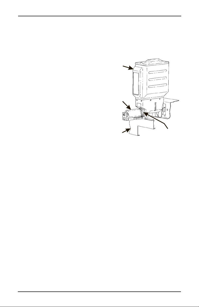
IV. Disengaging the Grinder
At certain times, the bean grinder(s) need to be disengaged from the bean canister(s).
WARNING
Keep your fingers clear of all moving par ts.
a. Using a screwdriver han-
dle or other suitable tool,
push up on the catch
GRINDER
BRACKE
ASSEMBL
spring far enough to free
the catch spring pin from
the grinder shelf bracket
assembly.
b. Pull the grinder and
CATCH
SPRING
grinder bracket assembly
towards you.
c. Pivot the grinder and
grinder bracket assembly
CATCH SPRING PIN
GRINDER SHELF
down.
d. Re-engage the grinder by pivoting it back up into position.
V. Canister Installation
a. Place the canister
in position as
shown.
b. En gage the pins
FILL
CANISTER
PINS ON MOTOR
SHAFT MUST ENGAGE
SLOTS IN CANISTER
COUPLER
on the motor shaft
with the slots in
the canister coupler.
c. Fit tabs on canis-
ter into the slots
on the canister
shelf.
d. To ensu re canis-
ter is correctly
engaged with the rear mounting bracket, gently push down on the fron
edge of the canister lid.
CANISTER
SHELF
626P0017
e. Canister Caps. The parts bag contains a number of red vinyl caps.
Place these caps over the canister nozzle as shown to avoid spilling
product when removing and replacing the canisters.
34 6530006
March, 2001
Page 39

Hot Drink Center Set-Up Manual
SANIT ATION
I. Basics
INTRODUCTION
Anybody who services vending machines must use proper sanitizing procedures.
Health regulations require that hands be clean when cups, commodities, and
food-contact parts are handled or serviced.
In addition, Federal and State Health Departments require regular cleaning and
sanitizing procedures for food contact parts.
The information in this section will explain how to clean and sanitize the merchandiser on a day to day basis. A clean and well maintained merchandiser will
provide a better product and greater safety for your customers.
CLEANING AND SANITIZING -- WHAT’S THE DIFFERENCE?
Clean means “free of visible soil”. In cup vending machine servicing, cleaning is
also done to maintain product quality and to remove food soils, oils, and mineral
stains that could affect product taste, aroma, and appearance.
Sanitizing means the reduction, to safe levels, of the number of disease-causing
bacteria that remain on the surface after cleaning. Therefore, cleaning and sani
tizing are done in separate steps, as prescribed by health regulations and good
industry practice.
-
When you sanitize you create a healthy and hygienic condition. This leads to
wholesome food, which in turn leads to satisfied customers.
SANITIZING IS NO SUBSTITUTE FOR A GOOD CLEANING
HOW DO I SANITIZE?
You can sanitize by using either of these two methods:
Chemicals: The object to be sanitized is treated with a bactericidal compound.
Heat: Raise the temperature of the object high enough to kill bacteria.
Water must be at least 170° F.
Hot brew water (if available) is an acceptable sanitizer. When food contact
surfaces are washed and/or rinsed, use the hot water available in the
machine.
Turn the machine off before using water on the machine.
6530006 35
March, 2001
Page 40

Hot Drink Center Set-Up Manual
In either case, the object must be thoroughly clean and completely rinsed i n order
for the sanitizing process to work. Caked-on soils not removed by cleaning, for
example, may shield bacteria from a sanitizing solution.
A GOOD PLACE TO START -- YOUR SANITATION KIT
You need to be sure that each machine is clean, safe, and functioning when you
leave it. In order to properly do this, you need to have a complete set of the right
tools. In addition to the screwdrivers, pliers, and test equipment necessary to
repair a machine, you need to have the tools to clean the machine.
Here is a checklist of the items needed for a good sanitation kit:
Sanitation pail
Tube and nozzle brus hes for food contact surfaces
Utility brush for dry spillage around canisters, etc.
Disposable towels, wet-strength and lint-free
NOTE
Wiping wit h towels can recontaminate sanitized food-contact
parts. Therefore, towels should not be used to dry food-contact
surfaces. Instead, these parts should be air dried.
Spray detergent, diluted to desired strength
Urn cleaner packets for coffee stains and oils
Odor control chemicals for pails
Replacement parts (if the exchange method is used)
Cabinet polish or window cleaner for the outside of the machine
Feel free to add some items to this list. For example, you may want to use a portable vacuum cleaner.
36 6530006
March, 2001
Page 41

Hot Drink Center Set-Up Manual
II. Clean the Hot Water Tank
Some smell and/or taste problems may occur in new machines. Follow this procedure to clean the hot water tank if you experience problems:
7. If the machine is in service, remove power from the machine.
8. Dissolve 1 tablespoon of common baking soda in a cup of water.
WARNING
The water tank may be HOT. Be careful when working on the
tank.
9. Loosen or remove the hot water tank lid and pour th e baking soda solution into the tank.
10. Apply power to the machine.
11. If the tank is not full, fill it.
12. Allow the tank to reach its operating temperature.
13. Leave the solution in the tank for AT LEAST ½ hour. If possible, leave the
solution in the tank for 1 hour.
14. Drain the tank.
15. Refill the tank, then drain again.
16. Refill the tank and put the machine back into service.
III. Sanitation Procedures
Refer to the recommended cleaning and sanitat ion interval table on the fi nal page
of this section. For each item, complete the procedure as outlined here.
Food-Contact Parts
NOTE
All food-contact parts must be cleaned and sanitized. Air dry,
do not wipe dry.
Ingredient Canisters - Empty and wash the canisters, augers, and spouts.
Sanitize with hot water and allow to air dry completely before returning to
cabinet.
Mixing Bowls - The inside of all mixing bowls can be rinsed by performing
the “Bowl Rinse” operation as outlined in the Programming sectio n of this
manual.
If needed, remove mixing bowls from the dry ingredient shelf. Wash the
mixing bowl lids and sanitize with hot water. Allow to completely air dry
before reassembling.
Whipper Lids and Impellers - Remove lids and imp ellers from the whipper housings, wash the lids and impeller housing. Sanitize with hot water
and allow to air dry before reassembling.
6530006 37
March, 2001
Page 42

Hot Drink Center Set-Up Manual
Beverage Discharge Nozzles - Disconnect the beverage dispensing tube
from the nozzles. Remove the n ozzles from the mou nting bracket. Remov e
the cap from the nozzle, wash clean and sanitize the nozzles and cap. Refer
to the tubing connection diagram for proper routing.
Brewer, Brewer Basket, and Brewer Funnel - The tubing and brewer may
be sanitized by performing the BREW RINSE operation as outlined in the
programming section. The machine features an automatic brewer sanitizing
feature also described in the programming section.
At times, it may be necessary to wash and sanitize the individual brewer
parts. If so, disconnect the tubes from the brewer manifold. Remove the
brewer barrel and manifold assembly from its support. R emov e the brewer
basket and funnel assemblies.
Thoroughly wash all parts using soap and water. Sanitize by rinsing thoroughly with hot water.
Coffee Chutes - Remove the metal chute(s), wash clean, and sanitize by
rinsing with hot water. Air dry before reinstalling.
Condiment Chute Assembly - Remove the condiment chute and cover
from the condiment canisters. Thoroughly wash all parts using soap and
water. Sanitize by rinsing thoroughly with hot water.Non Food-Contact
Parts
Non Food-Contact Parts
Cup Delivery Compartment - Remove the compartment from the mer-
chandiser. Wash clean and rinse with hot water.
Exhaust Fan Filter - Remove the filter from its housing. Wash with soap
and water, rinse, wring dry, and replace into housing.
Waste Pail - Empty, wash, and rinse with hot water. Sprinkle detergent
powder in the bottom of the pail to help control odors.
Ingredient Rinse Tray - Remove product canisters. Wash and rinse with
hot water. Allow to air dry.
38 6530006
March, 2001
Page 43

Hot Drink Center Set-Up Manual
IV. Overall Cleaning
Inspect your merchandiser both inside and out. Be sure to check corners and all
less visible parts of the merchandiser.
Clean where needed.
Allow the inside of the cabinet to dry thoroughly before you close the door.
National Vendors recommends using the following s upplies:
• A commercial glass cleaner on the glass in the cabinet door.
• A mild detergent and warm water on the cabinet, brewer, and other NON
ELECTRICAL components.
WARNING
The plastic parts in your merchandiser shou ld be cleaned with
mild detergent and warm water. The use of other cleaning
agents may damage the material, and should be avoided.
V. Preventive Maintenance Cleaning
Periodically, you should visually inspect your merchandiser's hot water tank for
excessive lime and scale buildup. This buildup on the tank walls, water valves,
and heater element will vary dramatically, depending upon water quality. You
should develop a cleaning and deliming schedule based on the apparent local
water quality.
NOTE
To aid in removing scale from your merchandiser, National
Vendors has a service kit available: part number 6400080. In
addition, if your machine has the Everpure water inlet filter
system option, a second kit (part number 6400086) is also
available.
6530006 39
March, 2001
Page 44

Hot Drink Center Set-Up Manual
TUBE ROUTING DIAGRAM
40 6530006
March, 2001
Page 45
Hot Drink Center Set-Up Manual
SEMI-
ANNUALLY
CS
CS
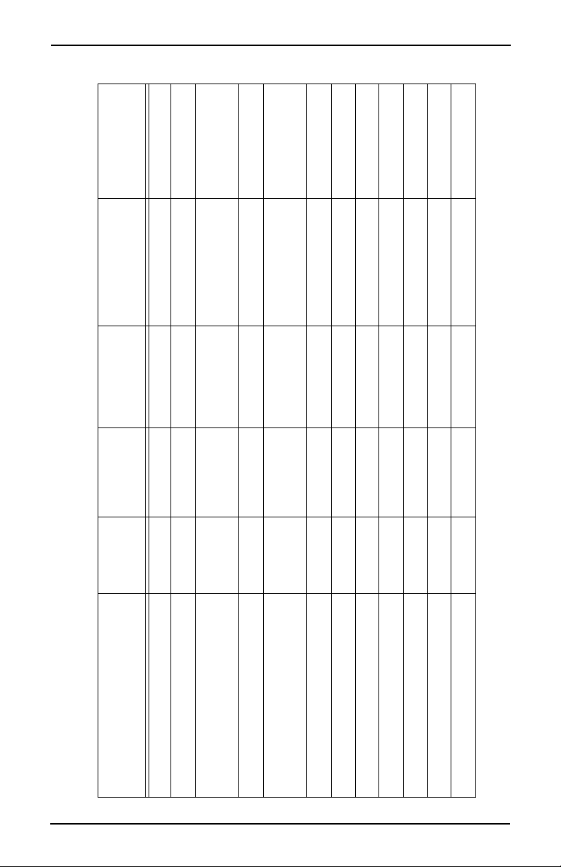
Recommended Cleaning And Sanitation Intervals
ITEM DAILY WEEKLY MONTHLY QUARTERLY
Ingredient Canisters CS
Mixing Bowls CS
Whipper Funnels and
Impellers
Beverage Discharge Nozzles CS
Brewer, Brewer Basket and
Brewer Funnel
Bean Grinder Coffee Chutes CS
Bean Grinder Housing S
Brewer Mechanism C
Cup Delivery Compartment C
Exhaust Fan Filter C
Grounds Pail C
Waste Pail C
S = Sanitize at this interval C = Clean only at this interval
6530006 41
March, 2001
Page 46
Hot Drink Center Set-Up Manual
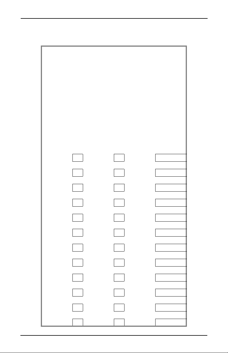
Make copies of this cleaning record, cut it out, and keep it in the plastic bag
mounted on the inside of the door. It will be your record of cleaning your Hot
Drink Center.
Record of Cleaning
20_____
S
RT
A
JAN
FEB
P
T
C
A
T
N
O
C
D
O
O
F
N
O
N
N
O
C
D
O
O
F
S
RT
A
P
T
C
A
T
Y
B
MAR
APR
MAY
JUN
JUL
AUG
SEP
OCT
NOV
DEC
42 6530006
March, 2001
Page 47

Hot Drink Center Set-Up Manual
APPENDIX A. THE FREE VEND KEYSWITCH OPTION
The free vend keyswitch allows someone to set up free vending without needing
to open the door.
It is a good idea to establish a free vend code. This will prevent an unauthorized
person from setting the machine to free vend, even if they have a key.
1. Press . Enter your 4-digit supervisor code. Press .
2. Press again, then press until the disp lay shows FREE XXXX. Enter a 4-digit free vend code.
NOTE
To keep the user from having to enter a code, you can enter
0000 as your code. See the steps below for details.
3. CONTINUE.
USING THE FREE VEND KEY SWITCH:
If you have set your freevend option to FREE W/KEY:
4. Place your key in the free vend keyswitch and turn it to the right. (If the keyswitch is already turned to the right, turn it to the left, then back to the right.) The di splay shows: ENTER CODE.
NOTE
If your freevend code is set to 0000, you will not see this display. Skip to step 6.
5. Enter your 4-digit freevend code. If you do this successfully within 6 seconds, you will hear two beeps, and the display shows: UNLOCKED.
6. The display shows NO MONEY REQUIRED (or whatever custom message you set up for the freevend period). Remove your key. All vends are free until the keyswitch is turned to the left again.
7. To take the machine off free vend, insert your key, turn the keyswitch to the left, and remove the key.
If you have set your freevend option to FREE OFF or FREE ALL:
1. If the freevend key is turned to the right, the machine will go out of service.
6530007 A-1
March, 2001
Page 48

Hot Drink Center Set-Up Manual
Notes . . .
________________________________________________________________
________________________________________________________________
________________________________________________________________
________________________________________________________________
________________________________________________________________
________________________________________________________________
________________________________________________________________
________________________________________________________________
________________________________________________________________
________________________________________________________________
________________________________________________________________
________________________________________________________________
________________________________________________________________
________________________________________________________________
________________________________________________________________
________________________________________________________________
________________________________________________________________
________________________________________________________________
________________________________________________________________
________________________________________________________________
________________________________________________________________
________________________________________________________________
A-2 6530007
March, 2001
Page 49

Hot Drink Center Set-Up Manual
APPENDIX B. THE INFRARED MUG/CUP SENSOR
The infrared mug/cup sensor can sense the presence of a mug or cup without
using movin g parts.
Indicator Light
The sensor is equipped with an indicator light. This light will help you get the
best results from the infrared mug/cup sensor.
Under these conditions, the indicator light should be off:
• Machine door open
• Cup station in place
• No cup in the station
If it is on, it is indicating improper cup station alignment or excessive sensor sensitivity.
Testing the light...Under these conditions:
• Machine door closed
• Cup station in place
• No cup in the station
Press any letter on the selection switch panel, for example, A. Only the letter A
should be showing in the message display. If “A MUG” is displayed, the sensor
thinks there is a mug in the station. The fault could be one or more of the follow
ing:
-
• Improper cup station alignment
• Excessive sensitivity (the sensor is sensing the delivery door)
• Cup station lens is not clean
Cleaning
As indicated in the Sanitation section, you should remove the cup s tation to clean
it. Pay particular attention to the dark colored infrared mug/cup sensor lens,
which is part of the cup station. If it is not thoroughly cleaned, the sensor will not
work properly.
CAUTION
Do not get liquid inside the sensor unit.
Cleaning the infrared mug/cup sensor unit itself is not usually necessary. If it
does require cleaning, just wipe it with a damp cloth.
6530007 B-1
March, 2001
Page 50

Hot Drink Center Set-Up Manual
Calibration
1. Remove the plastic cap in the rear of the sensing un it, exposing the potentiometer adjusting screw, as shown in figure B1.
2. Turn the screw clockwise to in crease sensitiv ity of cup detection, or counterclockwise to decrease sensitivity.
3. Calibrate the sensor:
CAUTION
Do not adjust sensitivity too far, or unreliable sensing could
result.
a. Using a piece of WHITE poster bo ard or h eavy cardb oard , make a 5" x
5 5/8" target.
NOTE
IT IS VERY IMPORTANT THAT THIS MATERIAL BE
WHITE.
b. Place the target in the cup station just beyond the cup deflectors (see fig-
ure B-2). The target should be standing vertically; not tilted forward or
backward.
c. With the target in place, turn the adjusting screw clockwise very slowly
until the indicator just turns ON.
d. Turn the adjusting screw counterclockwise very slowly until the indica-
tor just turns OFF.
4. Replace the plas tic cap.
5. Insert a mug into the cup station in the vending position and check to see that the red indicator light is ON.
This calibration will be adequate for most cups or mugs. In some cases, a
slightly more sensitive setting is needed if the cup or mug is a dark color.
B-2 6530007
March, 2001
Page 51

I
NDICATOR
D
VIEWING REAR OF SENSOR ASSEMBLY
PLASTIC CAP
T
LIGHT
Hot Drink Center Set-Up Manual
ADJUSTING SCREW
Figure B1.
PLASTIC CAP
SHOWN REMOVE
INDICATOR LIGH
CUP
DEFLECTORS
CUP
Figure B2.
6530007 B-3
March, 2001
Page 52

Hot Drink Center Set-Up Manual
Notes . . .
________________________________________________________________
________________________________________________________________
________________________________________________________________
________________________________________________________________
________________________________________________________________
________________________________________________________________
________________________________________________________________
________________________________________________________________
________________________________________________________________
________________________________________________________________
________________________________________________________________
________________________________________________________________
________________________________________________________________
________________________________________________________________
________________________________________________________________
________________________________________________________________
________________________________________________________________
________________________________________________________________
________________________________________________________________
________________________________________________________________
________________________________________________________________
________________________________________________________________
B-4 6530007
March, 2001
Page 53

Hot Drink Center Set-Up Manual
APPENDIX C. DEX/UCS INTERFACE OPERATION
Connect your portable data collection device (PDCD) to the harness hanging
inside the monetary door, and operate it per its instructions.
SELECT DATA TRA N SFER METHOD:
6. Press . The display shows: ENTER CODE. You must enter the fourdigit supervisor code within 6 seconds to gain access.
NOTE
A new machine has a factory-set supervisor code of 0000.
When you have entered the right code, you will hear two beeps and see
SUPERVISOR in the display.
7. Press until the display sh ows DEX+CLR or DEX ONLY.
DEX+CLR = Data will be cleared after collection is complete.
DEX ONLY = Data will remain in merchandiser memory after collection is
complete.
NOTE
A third selection - PRINTER - is available, but selecting it will
disable the dex/ucs interface.
8. Press to switch between the two options.
9. Press to exit.
This procedure does not need to be repeated u nless you des ir e to change the d a ta
transfer option. However, it might be prudent to check the setting prior to down
load to ensure unintentional clearing of data.
DOWNLOAD DATA:
1. Press . The display shows DEX.MODE while data is being transferred.
6530007 C-1
March, 2001
-
Page 54

Hot Drink Center Set-Up Manual
Notes . . .
________________________________________________________________
________________________________________________________________
________________________________________________________________
________________________________________________________________
________________________________________________________________
________________________________________________________________
________________________________________________________________
________________________________________________________________
________________________________________________________________
________________________________________________________________
________________________________________________________________
________________________________________________________________
________________________________________________________________
________________________________________________________________
________________________________________________________________
________________________________________________________________
________________________________________________________________
________________________________________________________________
________________________________________________________________
________________________________________________________________
________________________________________________________________
________________________________________________________________
C-2 6530007
March, 2001
Page 55

Hot Drink Center Set-Up Manual
APPENDIX D. MODIFY CANISTER TO VEND 12 OZ.
CUPS
Proceed as follows:
2. Remove all cups, then remove the turret center and turret base assembly from the canister.
3. Break off all 8 tabs on the bottom of the turret base as shown.
NOTE
You will no longer be able to vend smaller cups from this
canister! To return to vending smaller cups you must
replace the modified turret base with an original turret
base (part number 6233048) from National Vendors Parts
Department.
4. Replace the turret center and turret base in the canister and load cups.
5. Dro p a cup. If it drops pro perly, you are finished with the procedure, if not,
continue with step
6. Remove all cups, then remove the canister from the cup mechanism assembly.
7. Remove the funnel, replace the canister, and reload cups.
8. Dro p a cup. If it drops pro perly, you are finished with the procedure, if not,
continue with step
9. Order a universal cup ring (part number 6333008) from National Vendors Parts Department.
6.
9.
6530007 D-1
March, 2001
Page 56

Hot Drink Center Set-Up Manual
P
TURRET
CENTER
TURRET
BASE
BREAK OFF
ALL TABS
OPTIONAL
TWIN DRINK
CENTER CU
CANISTER
TURRET
CENTER
TURRET
BASE
BREAK OFF
ALL TABS
CANISTER
FUNNEL
D-2 6530007
March, 2001
Page 57

WARRANTY STATEMENT
LIMITED WARRANTY. Subject to the limitations specified herein, this mer chandiser is warranted for one (1)
year against defective parts and workmanship. Any part or parts which are proven to be defective within one
(1) year of the date of shipment will be repaired or replaced free of charge when the defective part is returned,
with transportation charges prepaid, to the destination designated by CRANE MECHANDISING SYSTEMS
Warranty Department.
Refrigeration system’s are warranted for (2) years against defective parts and workmanship. Any part or parts of the
refrigeration system which are proven to be defective within (2) years of the date of shipment of the merchandiser
will be repaired or replaced free of charge when the defective part(s) is r eturned, with transportation charg es prepaid,
to the destination designated by the Crane Merchandising Systems Warranty Department. Any part or parts that are
proven to be free from defect will be assessed a diagnostic charge. This diagnostic charge will be added to the price of
any replacement unit which might have been sent as an advanced replacement, as well as any shipping and handling
fees that may have accrued as a result of shipping the original refrigeration unit. The charges will be the sole respon
sibility of the original purchaser.
This warranty does not include any cost of service rendered or repairs made by cu stomer or it’s agents on Merchandiser, or parts, unless authorization to incur such expense has been given in writing by CRANE MERCHANDISING
SYSTEMS prior to incurring such expense. This warranty does not cover labor and service charges performed by
CRANE MERCHANDISING SYSTEMS service technicians. Customer shall pay all labor costs with respect to war
ranty repairs.
This warranty does not apply to A) electrical components, wiring, or circuits and/or for all mechanical parts or assemblies damaged as a result of operating the Merchandiser at other than the design voltage and frequency specified on
the Electrical Rating Tag, or B) in event of vandalism, fire or negligence, or C) incandescent lamps, neon lamps, flu
orescent lamps, ballasts, starters or other expendable items or D) when other manufactured components are installed
in Crane Merchandising Systems Merchandisers.
-
-
-
Replacement parts sold by CRANE MERCHANDISING SYSTEMS as After Market shall be covered for three
months from the date shown on the parts invoice. Purchaser must obtain prior RETURN AUTHORIZATION for
return of all parts, following guidelines given by Crane Merchandising Systems
New, unused parts purchased as AFTER MARK ET, can be returned within 30 days from date of parts invoice, with
prior authorization from CRANE MERCHANDISING SYSTEMS.
CRANE'S LIABILITY FOR ANY AND ALL LOSSES AND DAMAGES TO CUSTOMERS RESULTING
FROM ANY CAUSE WHAT SOEVER INCLUDING CRANE'S NEGLIGENCE, ALLEGED DAMAGE OR
DEFECTIVE GOODS, IRRESPECTIVE OF WHETHER SUCH DEFECTS ARE DISCOVERABLE OR
LATEN T, SHALL IN NO EVENT EXCEED THE REPAIR OR RE PLACEMENT OF DEFECTIVE OR
DAMAGED GOODS OR, AT THE ELECTION OF CRANE, THE PURCHASE PRICE OF THE PARTICU
LAR GOODS WITH RESPECT TO WHICH LOSSES OR DAMAGES ARE CLAIMED. CRANE
RESERVES THE RIGHT TO REPLACE OR REPAIR DEFECTIVE OR DAMAGED GOODS WITH
REMANUFACTURED PARTS OR MACHINES.
THIS WARRANTY IS IN LIEU OF ALL OTHER WARRANTIES EXPRESS OR IMPLIED, INCLUDING
WITHOUT LIMIT ATION, W ARRANTIES O F MERCHANT AB ILITY OR FITNESS FOR A PARTICULAR
PUPOSE. CRANE MERCHANDISING SYSTEMS SHALL NOT BE RESPONSIBLE FOR CONSEQUEN
TIAL OR PUNITIVE DAMAGES. CRANE MERCHANDISING SYSTEMS NEITHER ASSUMES NOR
AUTHORIZES ANY PERSON TO ASSUME FOR IT ANY OBLIGATION OR LIABILITY IN CONNEC
TION WITH THE SALE OF SAID EQUIPMENT OR ANY PART THEREOF.
Crane Merchandising Systems
A CRANE CO. Company
12955 Enterprise Way
-
-
Bridgeton, MO 63044
-
Page 58

 Loading...