

Page 1

Model 6500
Refrigerated Glassfront
Set-Up / Programming / Parts Guide
DO NOT REMOVE
MANUAL FROM
MACHINE
GPL ♦ 165 Bridgepoint Drive ♦ South St. Paul MN 55075
GPL 6500 V2.0 0108
Part # 80390445001
Page 2

i
Page 3

Warranty.............................................................................................................................................................iii
Introduction.........................................................................................................................................................iv
Features .............................................................................................................................................................iv
Specifications ..................................................................................................................................................... v
Installation ..................................................................................................................................................... 1.01
Cautions ........................................................................................................................................... 1.01
Unpacking ........................................................................................................................................ 1.02
Leveling the Machine ...................................................................................................................... 1.02
Door Hinge ....................................................................................................................................... 1.03
Set Up Steps .................................................................................................................................... 1.04
Optional Equipment....................................................................................................................................... 2.01
Refrigeration.................................................................................................................................................. 2.02
Components .................................................................................................................................................. 3.01
Power Supply ................................................................................................................................... 3.01
Lighting System................................................................................................................................ 3.01
Main Product Shelves ...................................................................................................................... 3.01
Delivery Bin ...................................................................................................................................... 3.01
Vend Motors..................................................................................................................................... 3.02
Logic Board & Display...................................................................................................................... 3.03
Keypad ............................................................................................................................................. 3.03
Coin Mechs, Validators and Card Readers...................................................................................... 3.03
PosiVend™ ................................................................................................................................................... 3.04
Operating System.......................................................................................................................................... 4.01
Power Up State ................................................................................................................................ 4.01
Motor Scan....................................................................................................................................... 4.01
Standby ............................................................................................................................................ 4.01
Keypad ............................................................................................................................................. 4.01
Credit Accumulation ......................................................................................................................... 4.01
Vend Process................................................................................................................................... 4.02
Change Payback .............................................................................................................................. 4.02
Use Correct Change......................................................................................................................... 4.02
Token Vends .................................................................................................................................... 4.02
Accountability Information ................................................................................................................ 4.02
Shutdowns........................................................................................................................................ 4.02
DEX/UCS ......................................................................................................................................... 4.02
Programming................................................................................................................................................. 5.01
Service Modes.................................................................................................................................. 5.03
Parts .............................................................................................................................................................. 6.01
Service/Trouble Shooting.............................................................................................................................. 7.01
To achieve the most trouble-free operation from your Fusion Merchandiser, it is highly recommended that this
service manual be thoroughly read and the instructions followed pertaining to installation, servicing and
maintaining of the unit.
Should you have questions pertaining to this manual or the vendor, please contact your GPL distributor or
write directly to:
TABLE OF CONTENTS
Product Support Group
GPL
165 Bridgepoint Drive
St. Paul, MN 55107 USA
651-288-2975 or 800-523-5932
651-288-2971 (fax)
www.cranems.com
© 2007 GPL
ii
Page 4

GPL warrants these automatic merchandisers (the "Unit"), manufactured by it, to be free under normal use and service from defects in
material or workmanship for a period of two (2) years from the date of delivery of this Unit to the original purchaser who purchased the
Unit either directly from GPL or from an authorized GPL dealer or distributor (“GPL Dealer/Distributor”). This warranty extends only to
the original purchaser of the Unit, but only if purchased either directly from GPL or from an authorized GPL Dealer/Distributor (“Original
Purchaser”), and is limited to the repair or replacement, at GPL's sole option, of any part or parts of the Unit that are returned to GPL or
to the authorized GPL Dealer/Distributor from whom the Unit was originally purchased, with all transportation charges prepaid by
Original Purchaser, and which, on GPL's examination, such returned part or parts shall conclusively appear to have been defective.
This warranty does not extend to:
1. Any Unit, or part thereof, that was subjected to misuse, neglect, or accident by anyone other than GPL after its delivery to the
Original Purchaser;
2. Any Unit, or part thereof, that was modified, altered, incorrectly wired or improperly installed by anyone other than GPL or used in
violation of the instructions provided by GPL;
3. A Unit, or part thereof, which has been repaired or altered by anyone other than GPL or an authorized GPL Dealer/Distributor;
4. A Unit, or part thereof, which has had the serial number removed, defaced, or otherwise altered;
5. Any plastic or glass windows, lamps, fluorescent tubes, and water contact parts;
6. Any Unit used outdoors;
7. Any accessories used with the Unit that were manufactured by some person or entity other than GPL; or
8. Any Unit repaired within the warranty period with parts other than genuine GPL built or endorsed parts.
LIM ITE D E XP RE SS W AR R AN T Y
GPL DISCLAIMS ALL OTHER WARRANTIES OF ANY KIND AS TO THE UNIT AND ALL
WARRANTIES OF ANY KIND AS TO ANY ACCESSORIES. THIS DISCLAIMER OF
WARRANTIES INCLUDES (1) ANY EXPRESS WARRANTIES OTHER THAN THE
LIMITED WARRANTY PROVIDED ABOVE AS TO THE UNIT AND (2) ALL IMPLIED
WARRANTIES OF MERCHANTABILITY AND FITNESS FOR A PARTICULAR PURPOSE
AS TO THE UNIT AND ANY ACCESSORIES. UNDER NO CIRCUMSTANCES SHALL
GPL BE RESPONSIBLE FOR ANY INCIDENTAL, CONSEQUENTIAL OR SPECIAL
DAMAGES, LOSSES OR EXPENSES (INCLUDING BUT NOT LIMITED TO LOST
PROFITS, LOST SALES, INJURY TO PERSON OR PROPERTY) ARISING FROM OR IN
CONNECTION WITH THE USE OF, OR THE INABILITY TO USE, THE UNIT FOR ANY
PURPOSE WHATSOEVER REGARDLESS OF THE LEGAL THEORY (CONTRACT,
TORT OR OTHER). IN NO EVENT WILL GPL BE OBLIGATED TO PAY DAMAGES FOR
ANY AMOUNT EXCEEDING THE PRICE PAID FOR THE UNIT. No representative of GPL or any other
person is authorized to assume for GPL, or agree to on the behalf of GPL, any other liability or warranty in connection with the sale of
this Unit.
GPL reserves the right to make any changes or improvements in its products without notice and without obligation, and without being
required to make corresponding changes or improvements in Units theretofore manufactured or sold.
165 Bridgepoint Drive
South St. Paul, MN 55075 USA
651-288-2975
651-288-2971 (fax)
iii
Page 5
INTRODUCTION
The Fusion features simple operation and built in flexibility, as well as extensive diagnostics and error
reporting facilities to provide ease of maintenance.
HOW TO USE THIS MANUAL
This manual is divided into seven basic parts:
1. Unpacking and Installation.
2. Optional Equipment & Refrigeration
3. Components and Refrigeration.
4. Operating System.
5. Programming
6. Parts
7. Troubleshooting.
CAUTION: Certain procedures in both the operating section and the service
section require that voltage be on in the machine. Only, trained personnel
should perform this function. Exercise extreme caution while performing these
procedures. These procedures will be marked with the lightening bolt symbol
as it appears at left.
CAUTION: Certain procedures in both the operating section and the service
section require a qualified trained technician to perform the particular task at
hand. These procedures will be marked with the exclamation symbol as it
appears at left.
iv
Page 6

Features
FEATURES OF THE FUSION MERCHANDISER
STANDARD FEATURES
Up to 100 selections.
Multi drop buss capabilities (MDB).
Extensive diagnostics capabilities.
Friendly text-based interface.
Flexible spiral spacing for large products.
Eight-point star drive motor.
Dex/UCS compatible.
Food/Frozen hosting.
Real time clock.
Machine reset capability.
Chime.
Third payment system ready.
PRICING
Global pricing by machine or by shelf.
Extensive accountability, including all
discounts and free vends.
Shutdown capabilities
Combo vends.
Programmable spiral count.
Upload and download capabilities for pricing
and set up.
Programmable maximum payout.
SCROLLING DISPLAY
User friendly two-line scrolling display to help
with the selection process and provide
customer feedback.
User programmable point of sale and
operational messages.
2 line display with 20 characters on each line.
NOISE LEVEL
Operates at less than 70 db (A).
ACCEPTABLE AMBIENT OPERATING
TEMPERATURE RANGE.
All equipment manufactured by GPL is designed
to work properly in a temperature range of 10°C
to 38°C (50°F to 100°F) in still air (75% R.H.
non-condensing). The machine is capable of
being stored in a temperature range of -18°C to
68°C (0°F to 155°F).
iv
Page 7
Specifications
Fusion
Domestic Export
Specifications
Height
Width
Depth
Floor Space
Container Size
Voltage (AC)
Hertz
Standby Amperes
Running Amperes
Watts
Refrigerant Type 134A 134A
Refrigerant Charge 9.8 oz / 0.28 Kg
High Side Test Pressure
Low Side Test Pressure
Shipping Weight 693 lbs / 315 kg
SNACK/FOOD SPIRALS CANDY SPIRALS BOTTLE SPIRALS
6 – Item Spiral 3-3/32” 6 – Item Spiral 2-7/8” 6 – Item Spiral 2-7/8”
10 – Item Spiral 1-7/8” 15 – Item Spiral 1-1/8”
12 – Item Spiral 1-9/16” 18 – Item Spiral 15/16”
5 - Item Spiral 4-1/8” 5 – Item Spiral 4-1/8”
7 – Item Spiral 2-21/32” 7 – Item Spiral 2-1/2”
15 – Item Spiral 1-7/32” 9 – Item Spiral 1-15/16”
18 – Item Spiral 1” 10 – Item Spiral 1-3/4”
30 – Item Spiral 1/2” 12 – Item Spiral 1-1/2”
40 – Item Spiral 5/16” 24 – Item Spiral 11/16”
30 – Item Spiral 1/2”
40 – Item Spiral 3/16”
Spirals highlighted in bold are standard production spirals.
All other spirals are available through aftermarket parts only.
Measurement indicates maximum product thickness.
72" / 183 cm 72" / 183 cm
41.5" / 113 cm 41.5" / 113 cm
37.375" / 95 cm 37.375" / 95 cm
10.77 Sq. Ft./ 1 Sq Meter 10.77 Sq. Ft./ 1 Sq Meter
120V 230V
60Hz 50Hz
SPIRAL DEPTH CHART
GPL 6500 V2.0 0108 v
Page 8
Specifications
6 6 6 6 6
6 6 6 6 6
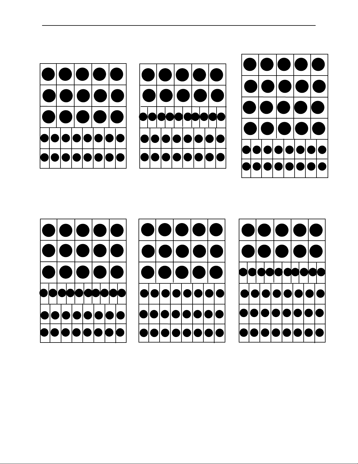
Machines are available with the spiral assortment shown below.
Figures in circles represent capacities of each spiral.
10 10 10 10 10
12 12 12 12 12
6 6 6 6 6
6 6 6 6 6
10
10 10 10 10 10
6 6 6 6 6 6 6 6
6 6 6 6 6 6 6 6
3·2 Food/Bottle
110 Food Capacity
96 Bottle Capacity
206 Total Capacity
10 10 10 10 10
10 10 10 10 10
12 12 12 12 12
15 15 15 15 18 18 18 18 18 18
6 6 6 6 6 6 6 6
6 6 6 6 6 6 6 6
2·1·2 Snack/Candy/Bottle
110 Snack Capacity
168 Candy Capacity
96 Bottle Capacity
374 Total Capacity
6 6 6 6 6
6 6 6 6 6
10 10 10 10 10
10 10 10 10 10
10 10 10 10 10
6 6 6 6 6 6 6 6
6 6 6 6 6 6 6 6
4·2 Food/Bottle
80 Food Capacity
96 Bottle Capacity
176 Total Capacity
10 10 10 10 10
12 12 12 12 12
15 15 15 15 18 18 18 18 18 18
15 15 15 15 18 18 18 18 18 18
6 6 6 6 6 6 6 6
6 6 6 6 6 6 6 6
2·1·1·2 Snack/food/Candy/Bottle
100 Snack Capacity
60 Food Capacity
168 Candy Capacity
96 Bottle Capacity
424 Total Capacity
6 6 6 6 6 6 6 6
6 6 6 6 6 6 6 6
6 6 6 6 6 6 6 6
3·3 Food/Bottle
70 Food Capacity
144 Bottle Capacity
214 Total Capacity
6 6 6 6 6 6 6 6
6 6 6 6 6 6 6 6
6 6 6 6 6 6 6 6
2·1·3 Snack/Candy/Bottle
110 Snack Capacity
168 Candy Capacity
144 Bottle Capacity
422 Total Capacity
GPL 6500 V2.0 0108 vi
Page 9
Installation
Cautions
The following cautionary information should be reviewed before the machine is installed. Following these
requirements and warnings are required.
CAUTION: This machine is designed for indoor usage only. Any other usage will void
the Manufacturers Warranty.
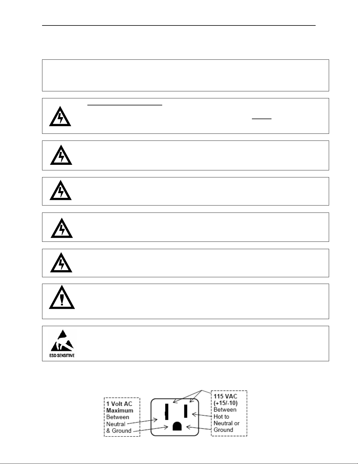
Voltage and Polarity Check
It is important that this machine is hooked up to the proper voltage and polarity for
your country. Use a voltmeter to verify voltage and polarity before connecting the
machine to a wall outlet. For machines located in North America, use the diagram
below to verify correct voltages.
CAUTION: Any procedure marked with the symbol at left requires that the Machine
have the power applied and a shock hazard exists.
CAUTION: It is important that this machine is hooked up to the proper voltage and
polarity for your country. Use a Voltmeter to verify voltage and polarity. Should the
reading be any different than a normal reading or if you are unsure of what the
reading should be contact an electrician.
CAUTION: Different countries may have unique plug arrangements. Ensure that the
machine is properly grounded before operating.
CAUTION: The power cord for all machines manufacturered for use outside of North
America are of a type Y attachment. If the power cord is damaged, it must be replaced
by the manufacturer, its service agent, or a similarly qualified person in order to avoid
a hazard.
Voltage and Polarity Check (for Machines located in North America Only)
It is important that this machine is hooked up to proper voltage and polarity. Using a voltmeter, perform the
following checks from the illustration below.
CAUTION: The machine is a heavy item. Ensure that sufficient personnel are available
for lifting and transporting the machine. Use proper lifting procedures and
equipment.
CAUTION: The system components in this machine utilize static sensitive
components. Precautions for handling sensitive devices should be observed when
handling these items.
GPL 6500 V2.0 0108 1.01
Page 10
Installation
C
the machine.
6”
The Fusion Line is assembled and packed so that
a minimum amount of time is necessary for
preparation to install it on location. The following
steps are recommended to insure correct
unpacking.
1. Shipping Damage: Thoroughly inspect the
exterior of the carton for damage which may
have occurred during shipment. Report any
damage to delivering carrier and follow their
instructions.
2. Remove the remainder of the packing
material. On machines shipped with the lock in
place, the keys are taped inside the coin
return.
NOTE: On the machine, the weight
concentration is toward the back of the
cabinet. Trucking and lifting should be
done from the back. CAUTION should be
taken when trucking from side.
3. On machines with lock in place, first unlock
and turn handle to open door. When no lock
is furnished, remove clip and turn handle.
Swing door to its full open position.
4. Remove all additional packing material from
the machine.
5. Warranty: The warranty card is attached to
the cover of this manual. It must be filled out
in full and mailed at once to insure coverage.
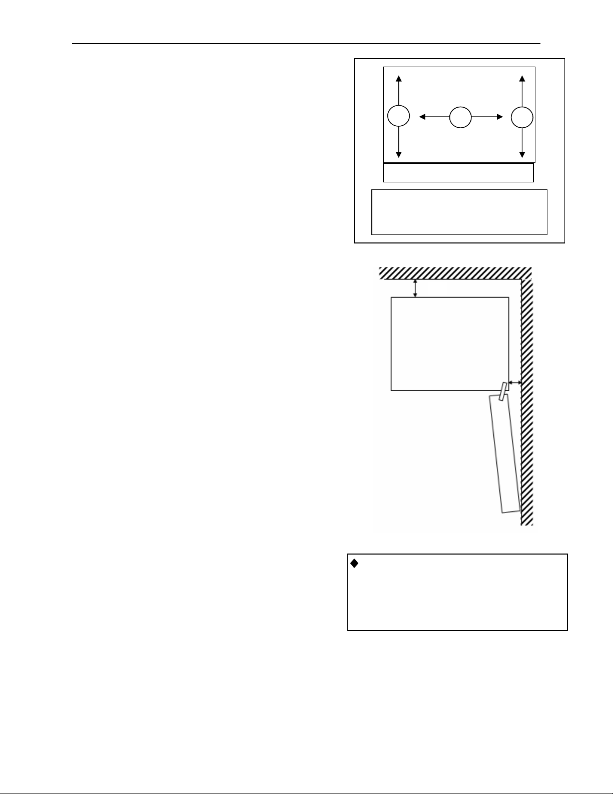
Leveling the Machine on location is important for
the proper function of the machine. There are four
leveling screws in the legs of the machine to make
any necessary adjustments. After positioning the
machine, level it from front to rear and right to left
directions. After leveling, turn front right (lock side)
leveling screw in about one-half turn to drop this
corner slightly to make the door easier to close
and lock.
Clearance Requirements
It is necessary on Fusion machines to have 6”
clearance behind the machine for air circulation.
A
B
DOOR
Place level in position A, and adjust the
bottom leg levelers, and repeat in
positions B & C
IMPORTANT: A set of anchoring brackets is
included with each machine. This kit is located
in the bottom of the machine with complete
instructions. It is recommended that this kit
be installed during set-up to prevent shifting of
GPL 6500 V2.0 0108 1.02
Page 11
Installation
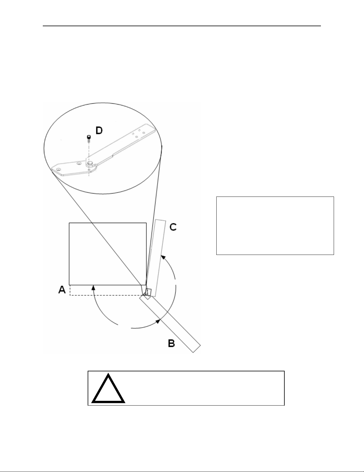
Door Hinge Swing
This machine contains a newly designed door hinge. The design of the door hinge controls the maximum distance
the door can swing open. The maximum opening position is reached when the screw is forced against the hinge
body. This screw can be removed during installation to permit the door to swing completely open and can help
maneuver the machine through a narrow doorway.
The screw should be replaced immediately upon reaching the machine’s final location. Failure to replace this
screw may result in damage to an adjacent machine or to the harnesses in the machine.
126°
CAUTION: The screw should be replaced immediately
upon reaching the machines final location. Failure to
replace this stop may result in damage to an adjacent
machine or the harnesses in the machine.
260°
Position A – Door Closed.
Position B – Door open to nominal
position with stop screw (D) installed.
Position C – Stop screw removed to
permit door to reach maximum swing.
GPL 6500 V2.0 0108 1.03
Page 12
Installation
Basic Set Up Steps
1. Remove all packing materials.
2. Adjust the scrolling price tabs on the
shelves.
3. Set prices and options on control board.
4. Set Clock.
5. Load machine adjust spacers or spirals
as needed.
6. Install product pushers as needed.
7. Add coins to coin mechanism.
8. Coin test.
9. Bill test if applicable.
10. Install lock cylinder if needed.
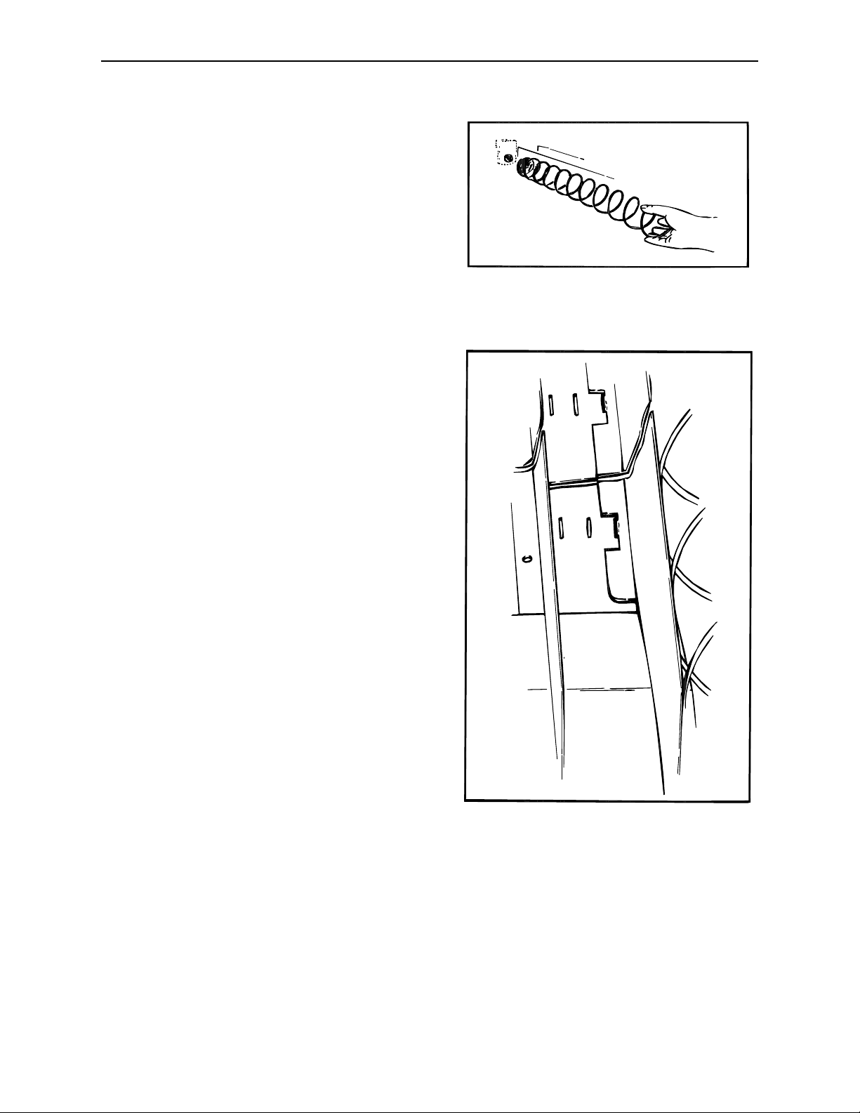
Loading Snack Shelves
Open the main door to its full open position. While
pushing down on the plastic lock lever located on
the right side of the shelf, grasp the shelf under
both front corners (see Figure 1). Lift the front of
the shelf slightly and pull forward until the shelf
reaches its stop. On shelves 1 through 4 the
shelves tilt down (do not drop) to make loading
easier. A new feature in the Fusion, the bottom 2
shelves do not tilt for easier loading. Only one
product shelf should be in the loading position at
any time. When returning a shelf, be sure the shelf
is in its full home or vend position. Begin loading
with the top shelf. Move it into the loading position.
The height spacing for items is greatest in this
shelf and the tallest bagged items should be
placed there. Soft items, such as pastry, pies,
etc., should be placed in the lowest snack shelf,
making the drop distance as short as possible.
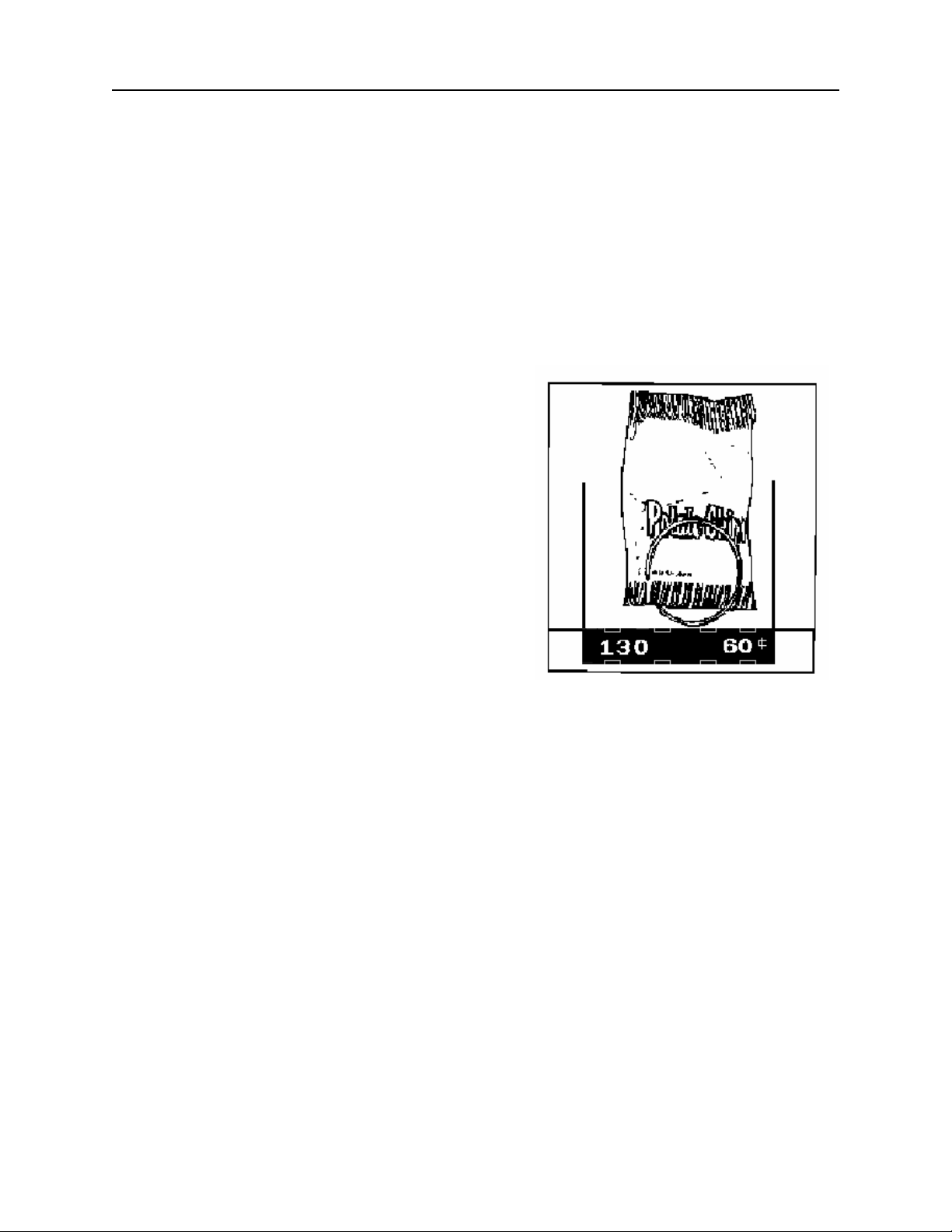
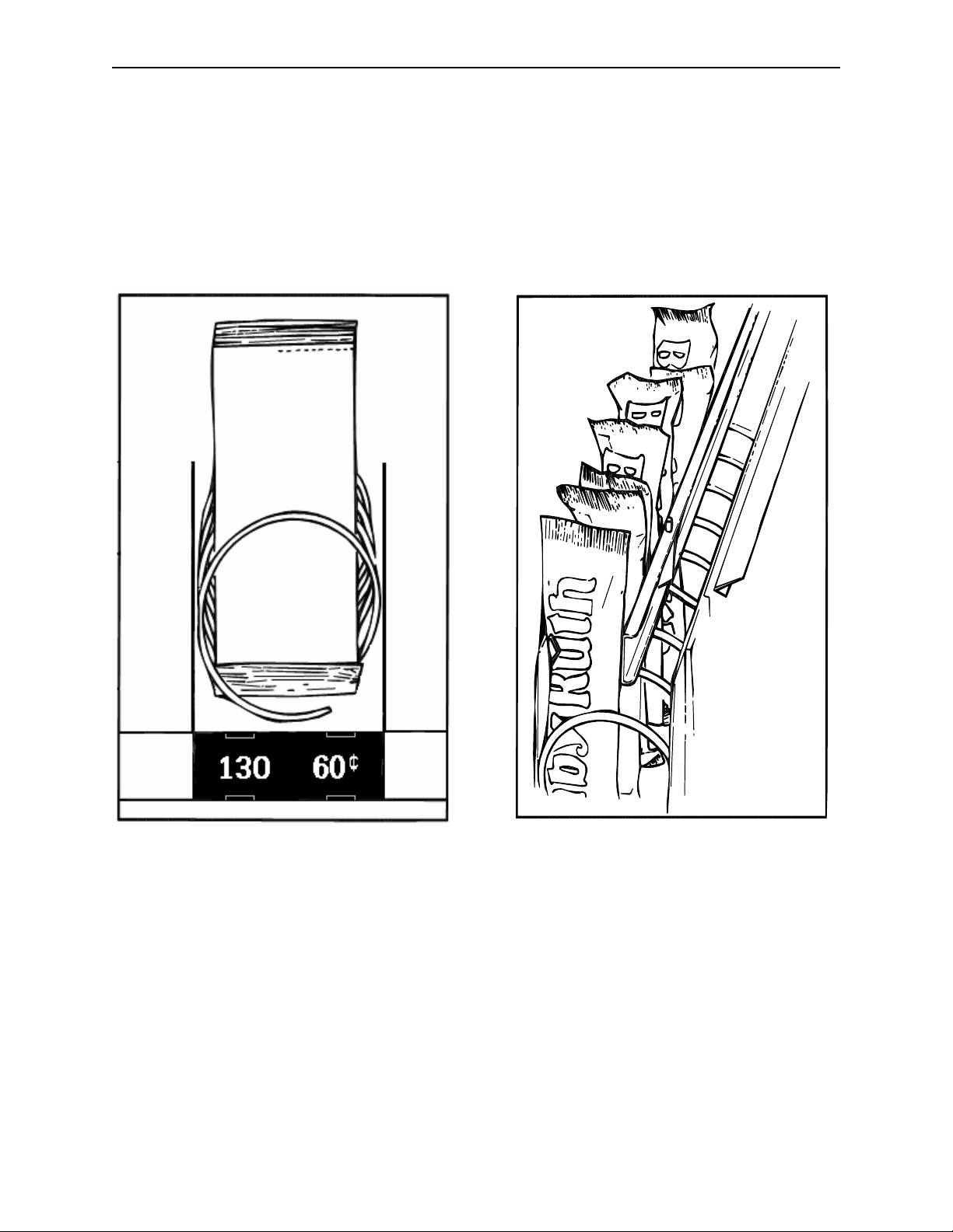
IMPORTANT: Product must not be forced into the
spiral spaces it should fit freely. If a product fits
tightly, use a larger pitch spiral. The bottom of the
product should be placed on top of the spiral wire
that rests on the shelf surface (see Figure 2). The
width of the product must be greater than the
diameter of the snack spiral. If it is smaller, the
product may fall through when it is in the front,
ready to vend position.
Figure 1: Moving shelf into the loading
position
Figure 2: Placement of product on main
product snack shelves and front end
position of spiral.
GPL 6500 V2.0 0108 1.04
Page 13
Installation
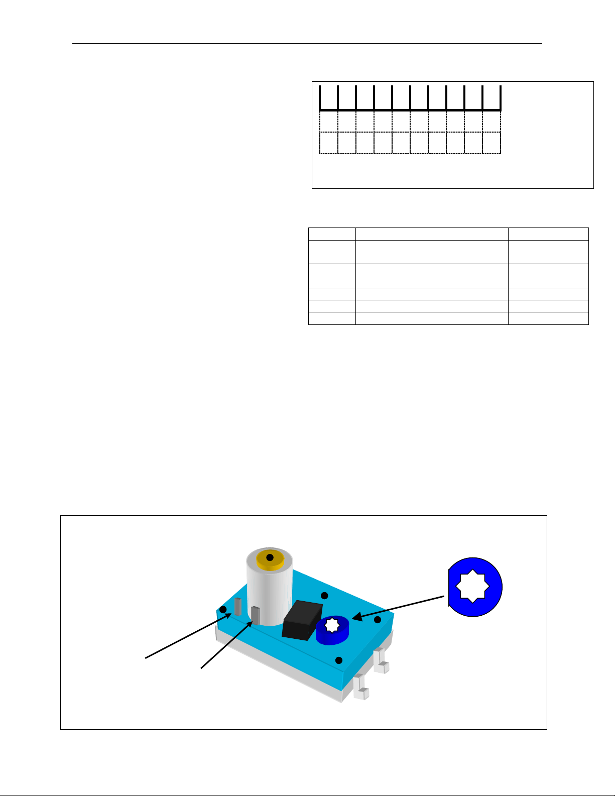
Adjusting the Stopping Position of the Spiral
One primary difference that distinguishes the
Fusion motor from previous motors is an eight
sided star at the drive hub of the motor. This
permits the stopping position of the spiral to be
customized by the operator to ensure the best
possible delivery of each product. To change the
stopping position of the spiral, remove the spiral
lock from the motor by pinching the shaft of the
spiral lock from the back side of the motor and
pulling forward on the front side of the spiral lock.
The spiral lock can be reinstalled in any of eight
different positions by turning the spiral lock to the
position desired and pushing the shaft of the spiral
lock through the eight sided star at the drive hub of
the motor.
Removal/Replacement of Spiral
Right Hand Spirals: Grasp the front of the spiral
and turn it clockwise. Lift the spiral up and off of
the spiral lock. When replacing a spiral attach it
around the tab on the spiral lock and turn the spiral
counterclockwise to lock it in place (see figure 3).
Pull lightly on the front of the spiral to ensure it is
locked in place.
Left Hand Spirals: Grasp the front of the spiral
and turn it counter clockwise. Lift the spiral up and
off of the spiral lock. When replacing a spiral
attaché it around the tab on the spiral lock and turn
the spiral clockwise to lock it in place. Pull lightly
on
the front of the spiral to ensure it is locked in place.
Product Spacers - 5 Selection Shelf
A product spacer is used to reduce the width of the
product area. This feature should be used on any
5-selection single spiral snack shelf where the
product width is 4" or less. Spacers should fit
within 1/8" of the product but should not fit tight
against the product. There are three positions in
each snack space where these spacers can be
placed. To install the spacer, align the lock ears
(on the lower edge of the spacer) with one of the
three sets of slots (one front and one rear). (see
Figure 4.) Push the spacer to the rear to allow the
ears to enter the slots, then allow the spacer to
move forward. Be sure the ears are in the same
set of slots, front and rear (see Figure 4).
Continue loading all spirals; adjust spacers where
needed in the top shelf. Return the top shelf to the
vend position and follow this procedure to load the
remainder of the large spiral shelves.
Figure 3: Removing and installing spiral.
GPL 6500 V2.0 0108 1.05
Page 14
Installation
Loading Main Product Candy Shelves
The 10-selection (candy type) shelves are loaded
similarly to the 5-selection shelves except that the
bottom of the product sits on the shelf in front of
the spiral wire (see Figure 5). These products
must also fit properly, and the product should fit
freely: do not force product into spiral.
Product Spacers-10 Selection Shelf
The 10-selection shelves are equipped with a product
spacer (see Figure 6) that can be pivoted from the
right side of every other product space. These
spacers should be pivoted out to hold the product
upright, but not tight against the product. Leave about
1/8" clearance between the spacer and the product.
Figure 5: Placement of product on candy
shelves and front end position of spiral.
GPL 6500 V2.0 0108 1.06
Figure 6: Candy shelf product spacer
positioned to hold candy upright.
Page 15
Installation
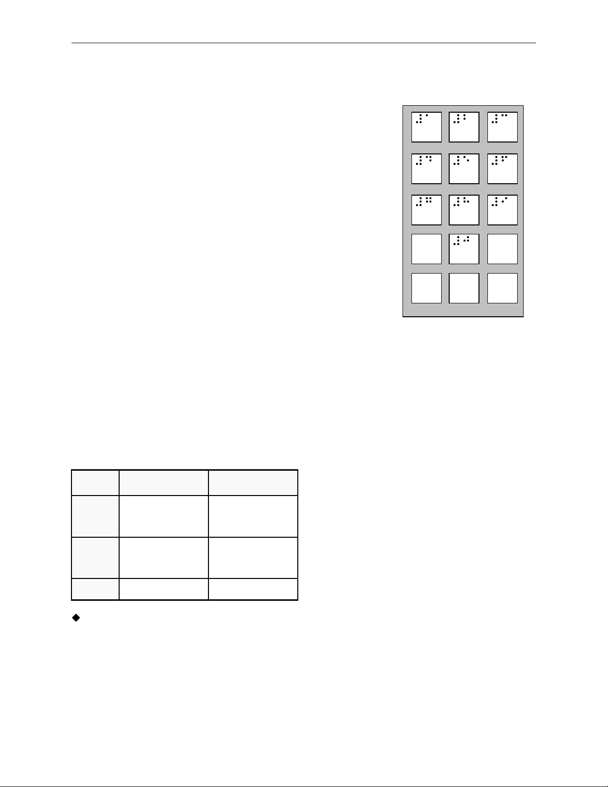
Product Pushers
Included with the machine are enough pushers for
you to install a pusher on each candy spiral. This
plastic part is designed to push the top of the
product forward while it is vending, helping it fall
from the shelf. It can also be used with products
that have the wrapper end flap on the outside of
the package. In this case, the pusher prevents
these products from hanging on the spiral by
spreading the flap. The pusher should be installed
at approximately the 1 o’clock position on the
spiral with the tab extending forward (see Figure
7). Locate the pusher in its proper position, hold it
against the spiral wire and push the semi-circular
part around the spiral wire. Black pushers
(#440215) are used on left hand spirals and white
pushers (#44014-1) are used on right hand spirals.
Black pushers are used on left hand spirals Note:
Not every selection spiral will need a product
pusher. (Example - Box Items.)
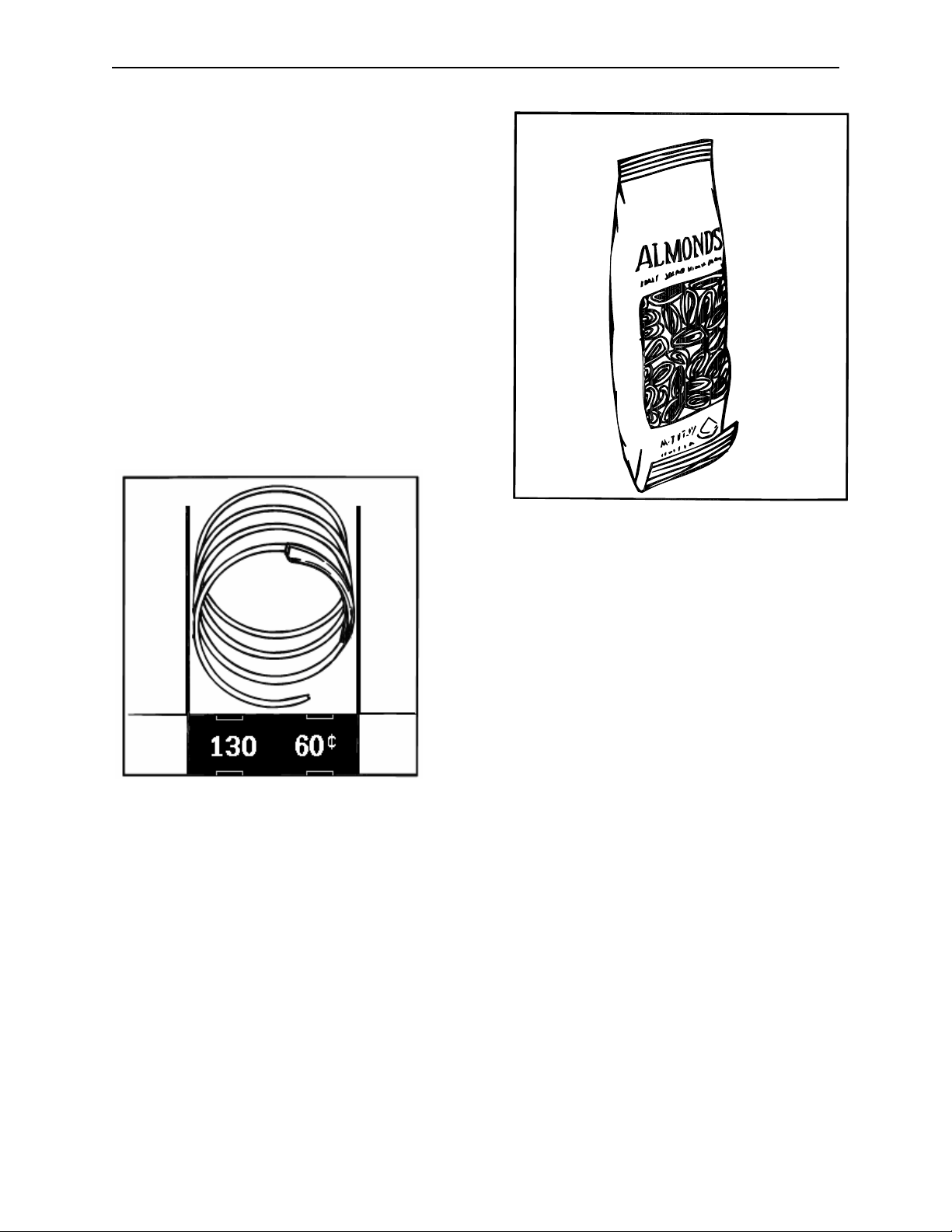
Figure 8: Fold bagged items bottom edge
forward and up.
Figure 7: Location of product pusher on
spiral.
Bagged or Boxed Items
Vending small bagged items in the 10-selection
shelves if not loaded properly could be a problem.
The sealed edge of the bag may get under the
spiral wire causing the product to hang up after it
has been vended. It is recommended that the
lower edge of these types of product be folded
forward and up (see Figure 8) next to the product
before inserting into the spiral space. It is also
recommended to use a slightly larger count spiral
for bagged items because of the product settling to
the bottom of the package.
GPL 6500 V2.0 0108 1.07
Cigarette Vending From the Fusion
Cigarettes can be vended from the candy shelves
using a (15 capacity) spiral for the soft pack regular,
king, 100 MM or 120 MM packs. A (12 capacity)
spiral should be used for (box) packs.
Lock Product Shelves
When all of the product has been loaded be sure all
shelves are returned to their vend position behind the
front roller guide.
Scrolling Price Tabs
Adjust the new scrolling price roles for each selection
in the machine.
Page 16

Installation
Cleaning
The Fusion will do the best merchandising job for
you if it is kept clean. The display window can be
cleaned with any good glass cleaner. The exterior
and interior surfaces should be cleaned with warm
water and mild detergent. Rinse thoroughly and
dry all surfaces.
CAUTION: Do not use any cleaners containing
silicon as this could cause electrical failures.
The main product shelves can be best cleaned
with the spirals and product spacers removed.
Refer to page 1.05 for removal of spirals and
removal of the product spacers.
Clean the acceptor on the coin mechanism or bill
validator frequently as accumulated dirt in this area
can cause poor acceptance on coins or bills.
Follow recommended cleaning procedures as
described by the coin mechanism or bill validator
manufacturer.
GPL 6500 V2.0 0108 1.08
Page 17

Optional Equipment
Dual Spiral Motors (Part # 360240)
Snack shelves can be set up to have dual spiral
selections. The dual spirals will help vend specialty
items better. These motors are available through
aftermarket parts only.
Half Cycle Motors (Part #360241)
The half cycle motors are used to vend thin items.
This motor is used with a product divider that is
positioned down the center of the coil. The product
is placed on both the left and right hand side of the
coil. When the motor turns, it turns only 180 degrees
(half revolution) rather than 360 degrees (full
revolution). These motors are available through
aftermarket parts only.
Touch Memory Harness
The touch memory harness (Part # 16800013) is
used in conjunction with the touch memory button
(CHIP) available separately (Part # 17500003). This
harness will allow you to download all settable data,
with the exception of the time and date. Once CHIP
is programmed you can take it to as many machines
as you wish to upload the information stored in
CHIP. CHIP can be programmed from a machine
that is already set up and then used to set up other
machines that are to be programmed identically. For
more information see Mode 30.
GPL 6500 V2.0 0108 2.01
Page 18

Refrigeration
The Refrigeration Unit
The Refrigeration Unit is comprised of a 1/3
horsepower compressor and is a hermetically
sealed system (no service ports). The refrigerant
used in the refrigeration system is 134a and the
charge is 9.8 ounces. The refrigeration system is
controlled by the Refrigeration Driver Board. The
Fusion glassfront merchandisers are designed to
operate at ambient temperature of 55ºF to 100ºF
(13ºC to 38ºC).
Refrigeration Processing:
The Refrigeration Driver Board (P/N 80492751)
maintains the temperature as measured by the solid
state temperature sensor. The refrigeration unit will
be turned on at the Set Temperature plus 3ºF and
will be turned off at the Set Temperature minus 3ºF.
A minimum of 1 minute is required for both the
cycle-on and cycle-off time of the relay. This insures
the compressor is not cycled on and or off too
rapidly.
Defrost Cycle
Independent of the temperature, the relay, therefore
the compressor, will be turned off for a defrost cycle
after 120 minutes of compressor run time. The
defrost cycle will last a minimum of five minutes or
until the temperature of the cabinet exceeds 45°F
(5.5°C). The power for the evaporator fan motor is
constant and continues to operate during a defrost
cycle.
Settable Temperature Range
The temperature for this machine when dispensing
perishable food is set automatically to 36°F when
“Food” is chosen as the machine type. When selling
non-perishable products and the machine type is set
to “Zone”, the settable temperature range is from
37ºF to 80ºF (3ºC to 27ºC). The recommended
temperature when the machine is equipped with
bottle shelves is 42°F (5.5°C). When using the
machine to dispense typical candy and
confectionary products, the recommended
temperature is 65ºF (18ºC).
Setting the Temperature
Refer to Service Mode 40 for the procedure to set
the temperature.
Checking the Current Temperature
The temperature inside the machine can be viewed
from the outside by pressing and holding the * key
for degrees °F or # key for degrees °C.
Refrigeration Driver Board (RDB)
The Refrigeration Driver Board (P/N 80492751) is
located inside the power supply box. The RDB has
the capability to maintain two temperatures, however
in this design, only the lower zone is monitored.
Power and communication to operate the RDB is
supplied via the MDB connector on the logic board
using a communications cable. Power to operate the
refrigeration unit is supplied to the Refrigeration
Driver Board immediately after the EMI filter and is
switched on and off by a relay on the Refrigeration
Driver Board.
Temperature Probe
The temperature probe (P/N 13600001-01) is
located in the cabinet below the bottom shelf on the
right hand side, just below the evaporator coil. The
probe is connected to JP3 on the RDB. An
unplugged or open temperature sensor probe will
display as -9ºF (-9ºC). A shorted probe will display
as 99ºF (37ºC).
For complete pin-outs of the Refrigeration Driver
Board, see the Troubleshooting Section of this
manual.
Health Control Check
Use this procedure to verify proper health control
operation.
1. Setup temperature. Note: Changing the setting
in Mode 40 to food will insure this is done
correctly.
2. Turn on Health Shutdown in Mode 42, be sure
to set all selections in the machine to on by
pressing 1** in the selection field.
3. Unplug the door switch from P2 of the logic
board to simulate door closure.
4. Close the door and allow the temperature in the
machine to stabilize. If the machine was at
temperature this will take a minute or less.
5. Once temperature has stabilized, open the door
and power down the machine. Note: the
evaporator fan will continue to run.
6. Leave the door open and let the machine warm
up for 6 minutes. Note: Do not leave the
machine powered down for more than 10
minutes.
7. Power the machine back up and within 3
minutes the machine should go into health
shutdown. The display should now show
“Selection 1XX Out of Service”.
8. Reset the temperature setting in Mode 40, if it
was changed in step 1.
9. Reset the Health Shutdown settings in Mode 42,
if they were changed in step 2.
10. Plug in the door switch and clear the error.
GPL 6500 V2.0 0108 2.02
Page 19
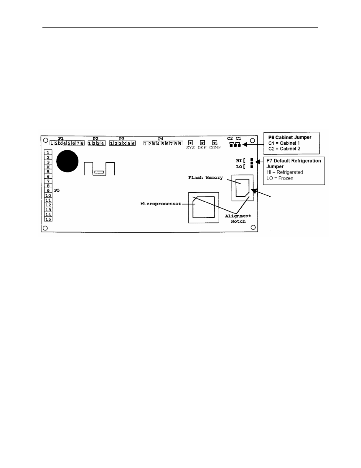
Hosting
The Fusion Machine may be used to host a 137/937 MultiMate machine. The following steps should be followed.
1. Check the software version of the MultiMate driver board. For the MultiMate to work properly with a Fusion
machine the driver board software must have Revision 9 or greater. Arrow A in the diagram below.
2. Set the cabinet jumper to cabinet 2. Jumper B in diagram below.
3. Plug the communications cable directly into the MDB plug on the Fusion control board.
4. Set the PosiVend selection in Mode 21 if applicable.
5. Set prices in Mode 20.
137/937 Instructions
B
C
A
GPL 6500 V2.0 0108 2.03
Page 20
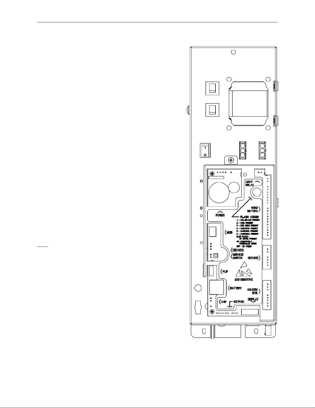
Components
Power Supply
The 120 VAC power cord from the wall outlet enters
the machine and plugs into the bottom of the main
junction box located on right side of the cabinet. The
junction box contains the power distribution
components, consisting of the control board, filter,
circuit breakers and the transformer. The voltage
outputs from the junction box to the board are 24
volts and 8 volts and plugs into the (P3 position) of
the Logic Board.
Lighting System
The Fusion machine features a new low voltage
LED color corrected lighting system. This system
consists of a 9.4VDC regulating power supply and
12 – 1 Watt LED’s producing 60 lumens of light.
Flexi Shelves
The Fusion machine features the new Flexi Shelf.
With the new Flexi Shelf all of the selection dividers
are removable allowing the shelf to be configured to
vend wide products such as submarine type
sandwiches. There are either five or six main
product shelves per machine. Each selection has its
own motor mounted to the back of the shelf. Every
shelf has its own harness and plug for connecting to
the remainder of the circuit through the cabinet
receptacle, located in the rear right of the cabinet. It
is possible to exchange a five selection shelf with a
ten selection shelf or visa versa. The tracks in the
back of the cabinet permit the vertical movement of
the shelves in one inch intervals. To do this the
shelf should be removed and the cabinet back
harness receptacle lowered or raised along with the
right & left shelf tracks.
Note
♦ When exchanging the shelves, you will not need
any parts but you will have to reprogram the
machines prices.
Pairable Motor Shelf
The Fusion models permit the pairing of two
sequential motors on a shelf. This feature allows 2
candy selections to be converted to a dual spiral
snack selection, by removing the product divider
between the spirals, and pairing the motors
electronically. See Mode 23 for additional
information on pairing motors.
Bottle Shelf
The Fusion model includes up to 3 – 8 select bottle
shelves. The bottle shelves can be raised or lowered
to vend up to 24 ounce bottles.
Delivery Bin
This is located below the display window on the door
and is mechanically operated.
GPL 6500 V2.0 0108 3.01
Figure 11: Power Supply Box.
Page 21
Components
Vend Motors
The vend motors used in the Fusion machines have
been specifically developed to operate with the GPL
Control System. One primary difference that
distinguishes the new motors from previous motors
is the presence of an eight sided star at the drive
hub of the motor. This permits the stopping position
of the spiral to be customized by the operator to
ensure the best possible delivery of product. Motors
are of the fast trac style, with all electronics required
to correctly operate the motor contained inside the
gear case or the motor housing and no external
control board. Each of the motors used with the
Fusion Control System will have two terminals. The
two terminals continue to be used to identify the
shelf and column (selection) to be vended.
Each motor requires two wires to operate correctly.
These wires are: shelf common, and selection.
Each selection on a shelf will have the same
common shelf wire - all shelf harness use wire #12
as a shelf common. This corresponds to the
selected shelf wire in the cabinet harness. The
terminal for the shelf common in the harness is the
smaller of the two.
Selection numbers are assigned from left to right,
starting with selection 0. Each selections number
corresponds to the number of the wire for that
selection.
Selection numbers in the Fusion Machines support a
three digit selection system. The first digit indicates
the cabinet number, the second digit is the shelf
number and the third digit is the selection number on
that shelf.
O O O O O O O O O O
0 1 2 3 4 5 6 7 8 9
12
12
12
12
12
12
12
12
SHELF WIRING DIAGRAM
Part # Case Color code Description
360275 1/2 blue, 1/2 white, 8 point star drive CW food/Snack
360276 1/2 blue, 1/2 grey, 8 point star drive CCW Food/Snack
360240 1/2 blued, 1/2 white, 8 point star drive Dual spiral
360241 1/2 white, 1/2 brown, 8 point star drive 1/2 cycle motor
Motors highlighted in bold are standard production motors.
All other motors are available through aftermarket parts
Fusion Motors.
only.
12
Selection Wire Number
12
Shelf Common Number
motor
motor
8 POINT STAR
DRIVE
Shelf Common
GPL 6500 V2.0 0108 3.02
Page 22
Components
1 2
4
3
5 6
7 9
0
8
C
<
Logic Board & Display
The control board contains all of the decisionmaking and display controls. All peripherals plug
into the controller. The all new Fusion display
contains 2 display lines each with a maximum of 20
characters. All Credit, Price, Diagnostic Information
and Options (In Service Mode) will be displayed on
this display.
A new feature added to the Fusion Machines is a
real time clock. This addition will allow the
programming of timed events such as discounts and
shutdowns (see the programming guide in this
manual for more details).
Keypad
The Selection keypad is located on the door directly
below the display. The Selection Keypad is used as
an input source for settable data while in the Service
Mode. The keypad is only active for service
functions when the door is open, so even in the
event of vandalism to the control bezel; no access to
the control functions is permitted.
Coin Mechs, Validators and Card Readers
The Fusion Machines support MDB protocol only.
The maximum number of MDB payment peripherals
is one coin mechanism, one bill validator, and two
card reader systems.
The Fusion will automatically determine at power up
which peripherals are connected and configure itself
accordingly.
Mars
CoinCo
Conlux
Contact your coin mechanism and validator
supplier for additional models.
MDB Coin
Mechanism
TRC-6510
TRC-6512
VN-4510
CF7512
9302-GX,
USQ-G701
USQ-G703
USQ-L701
USLZ-004-01F
CCM 5 G
MDB Bill Validator
VN2502-U5M
VN2602-U5M
BA32R
BA52R
MAG32
MAG52
USLZ-004-01F
#
Fusion keypad.
GPL 6500 V2.0 0108 3.03
Page 23

PosiVend™
GPL PosiVend™
Guaranteed Delivery System
Modes of Operation for the Fusion
Introduction
The premise behind the development and
introduction of PosiVend (PV) was to improve
customer (machine user) satisfaction by
guaranteeing delivery of the product they have
selected. In addition to increasing customer
satisfaction and loyalty, the guaranteed delivery of
products reduces operational costs and increases
efficiencies, therefore making the operator more
profitable.
An average service call costs between $65 and
$100. PosiVend reduces these costly calls for
product hang-ups and missed vends. PosiVend
also eliminates the time and costs associated with
credit vouchers due to missed vends. Lastly,
operators may risk losing an account if product vend
failure occurs on a repeated basis.
While careful and consistent loading of products
helps to ensure a positive vend, PosiVend provides
a positive vend solution that takes these variables
out of the equation, and works efficiently and
effectively to deliver the product.
Function
The GPL PosiVend Guaranteed Delivery System
consists of a series of 12 infrared pulsed beams that
create a web of interlaced beams just above the
opening of the delivery bin in our glass front
machines. When any one of these infrared beams is
broken by a product falling into the delivery bin
during a vend, the PV sensors transmit a signal to
the Logic Control Board that the vend occurred
successfully, and payment is collected, and change
is returned, if required. If the product is not delivered
successfully, the credit reappears on the display and
allows the customer to choose an alternate item, or
press the coin return to receive their money back.
Modes of operation
The PV system has three selectable modes of
operation: Off, Home, or Drop. The operator has
the option to choose any of these four modes, and
once a mode of operation is selected, choose which
selections in the machine will be monitored by PV.
Off Mode
When PV is set to Off, the PV system is disabled,
and all selections in the machine will run one time
only.
Home Mode
When PV is set to Home, and the customer makes
their selection, the selection motor begins its cycle,
and the PV sensor begins watching for a product to
fall into the bin. The selection motor makes a
complete revolution, returns to the home position,
and pauses for 2 seconds. If no product is detected,
the selection motor then runs a second
complete cycle attempting to deliver the product.
The motor pauses a second time, and if no product
was detected during this vend, the motor runs a third
complete cycle. If a product is delivered during any
of the three cycles, the purchase is completed, and
any change required is returned. If no product was
delivered during any of the three cycles, an error is
created (see PosiVend Errors below). The credit
reappears on the display and allows the customer to
choose an alternate item, or press the coin return to
receive their money back.
Drop Mode
When PV is set to Drop and the customer makes
their selection, the selection motor begins its cycle,
while PV sensor begins watching for a product to fall
into the bin. The selection motor makes a complete
revolution, returns to the home position, and pauses
for 2 seconds. If no product is detected, the
selection motor begins a second cycle, and if a
product interrupts the sensor beams, the selection
motor stops immediately, leaving the motor in an
off home position. If no product is detected during
the second cycle, the motor runs a third cycle, and
stops immediately upon detection of the product
dropping in the bin. If the motor is stopped in an “off
home”, position, the next time this item is vended,
the motor returns to home and pauses. If a product
is detected during this partial cycle, the motor
remains at home, and the transaction is complete. If
no product is detected, the motor begins a second
cycle, and if a product falling into the bin is detected,
the motor stops immediately, and the transaction is
complete. If no product was delivered during any of
the three cycles, an error is created (see PosiVend
Errors below). The credit reappears on the display
and allows the customer to choose an alternate
item, or press the coin return to receive their money
back.
PosiVend Errors
One of the critical new features of PosiVend is an
increase in the number and type of diagnostic errors
available to the technician to assist them in
determining the cause of a PV error. The table
below explains each of these available errors. More
detailed information on these errors is available in
the Troubleshooting section of this manual.
GPL 6500 V2.0 0108 3.04
Page 24

PosiVend™
POSIVEND XXX FAILED
After any selection motor (XXX) runs three times
without PV detecting a product, an error is posted,
and that selection is disabled from vending. If three
different selections are disabled with PV errors, then
a PV Disabled error is posted, and PV for the entire
machine is disabled, and all selections operate as if
PV was set to Off. For machines set to Home, this
disabled condition remains until the machine door is
opened and closed. For machines set to Drop the
“C” key on the keypad be pressed before closing the
door to return disabled selections to operation. The
errors will remain until they are cleared.
Three items missed by the
GOLDENEYE XXX FAILED
CABx GOLDENEYE ERROR
CABx TRAN + REC BAD
CABx RECEIVER Y BAD
CABx TRANSMTR Y BAD
CABx TRN Y TO REC Y
Choosing Between Drop vs. Home
Please consider the information below when
deciding which mode of PosiVend to use:
1) If a machine is set to the Drop mode, the
“automatic motor scan upon door closure to restore
all the motors to their home position” is disabled. To
perform a motor scan and cycle all motors to their
home position, you must first press the “C” key
on the Key Pad before closing the door. This
trademark feature of GPL equipment since 1985 is a
valuable diagnostic tool and it will also warn a route
service person if they have not pushed all the
shelves back into their normal position after
servicing.
Utilizing the drop mode disables the automatic
function of this important feature. Route service
personnel should be instructed to press Mode
Switch and the door switch to home all the motors
before filling the machine.
2) If a machine is set to the Drop mode, and a
route service person ignores the errors stored,
and closes the door without pressing the “C”
PosiVend Sensor. XXX indicates
which selection.
Three different selections in a
cabinet missed by the PosiVend
Sensor. X indicates which
cabinet
All Transmitters and Receivers
bad - X indicates which cabinet.
Receiver (Sensor) Y failed, Y
indicates the number of the
Sensor, X indicates which
cabinet
Transmitter (LED) Y failed, Y
indicates the number of the
LED, X indicates which cabinet
Transmitters Y not seen by
Receiver Y, X indicates which
cabinet
key, they will leave the previously disabled
selection still disabled, even though they may
have cleared any product jams or misloads, and
refilled the selection.
3) The Drop mode may leave some selections in an
“off home” spiral position. Historically, GPL snack
machine spirals self-home, so it is possible that
route service personnel and/or consumers may
question a selection’s off home spiral appearance.
Consumers may avoid that selection, or the machine
altogether, thinking that something is “wrong” with it.
This may lead to an unnecessary service call. When
using the either of the Drop modes you may want to
reassure your client that spirals in an “off home”
position are normal and will produce a positive vend
4) The Home mode keeps the “motor scan upon
door closure to restore all the motors to their home
position” automatically enabled.
5) The Home mode will always leave selections in
their home spiral position.
6) PosiVend could deliver a second product on a
failed vend. However, the extra occasional product
cost is well worth the savings of a service call due to
a product hang-up or missed vend.
GPL 6500 V2.0 0108 3.05
Page 25
PosiVend™
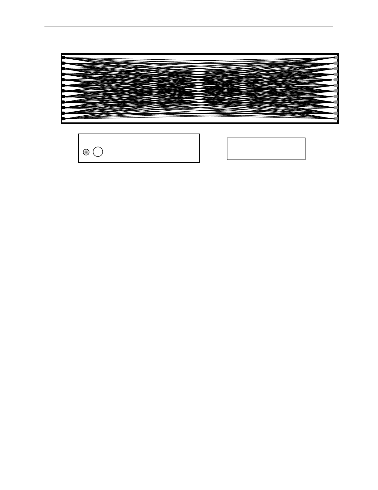
T1
R12
G/Eye
R11
R10
R9
R8
R7
R6
R5
R4
R3
R2
R1
Fusion Delivery Bin – drawn to scale
For scale, circle at left represents
a US dime and quarter.
PosiVend® sensor coverage looking down into the delivery bin.
Front of Machine - Glass
Inside of Machine
Rxx = Receiver number
Txx = Transmitter number
Cabinet 2
Cabinet 1 G/Eye
Connection
T2
T3
T4
T5
T6
T7
T8
T9
T10
T11
T12
Cabinet 2 G/Eye
Connection
GPL 6500 V2.0 0108 3.06
Page 26

Operating System
Power Up State
Following a power-up or reset condition, the display
will show “AUTOMATIC PRODUCTS“on the top line
and “GPL / CMS” with three bouncing dots on either
side on the bottom line.
Motor Scan
Upon closing the door the display will show the
firmware revision level (see Figure 11), perform a
diagnostic routine that will scan and home the
motors determining what motors exist in the
configuration. After completion of this scan, the
status of all the motors will be reported on the
display (see Figure 12).
Standby
In Standby, the operator selected message will
appear on both the top and bottom line. The factory
default messages are “Have a nice day” on the top
line, and “Credit .00” on the second line. See the
Operating system, Mode 60 for details on how to
change the standby message. As soon as credit is
deposited, the accumulated credit will be shown on
the bottom line until a selection is made.
Keypad echo
When the first numeric key is pressed the display
will show the selection number in the third leftmost
digit. This character will remain for 5 seconds or until
another key is pressed. Once all 3 keys are pressed,
the selection will be shown on the display for one
second and then the associated price for the product
will display. If the selection is disabled or shut down
(using the Shutdown pins) the display will show
“Invalid selection” for 5 seconds or until a new
selection key is pressed. If the selection is enabled
but not functioning properly (not present or not
home) the display will show “Make Another
Selection” for 5 seconds or until a new selection key
is pressed.
Credit Accumulation
Credit may be accumulated through a coin changer,
bill acceptor or card reader. A non-revaluing card
reader credit cannot be mixed with coin and/or bill
credit during a single transaction or vend. If card
reader revalues the coin & bill credit goes to the
card, and then a vend may still be attempted. Credit
acceptance will be disabled when the accumulated
credit equals or exceeds the highest priced item.
Credit accumulation from any source is disabled or
escrowed if change is not available. If the amount of
card reader credit available exceeds the maximum
displayable credit, the maximum credit will be
displayed.
GPL 6500 V2.0 0108 4.01
Field A
MOTORS BEING SCANNED
P07 L00.21 C1-- C2--
Field B
Field C
FIGURE 11
Field A is the informational heading.
Field B is the microprocessor version
number.
Field C is the software version number.
Field D is the software version in the
temperature control board for cabinet 1.
Field E Is the software version in the
temperature control board for cabinet 2.
Field A
Field E
Field D
NO SHELF X
GD=XXX BD=XXX NP=010
Field B
Field C
FIGURE 12
Field A shows the lowest shelf number not
found during the automatic scan of motors.
Field B is the number of good motors.
Field C is the number of bad motors.
Field D is the number of motors not present.
Field D
Page 27
Operating System
Vend Process
After a keypad entry is made the logic board
determines if sufficient credit is available for the
selection attempted. If the credit is greater than or
equal to the selection price, a vend attempt will be
made for that selection. During this time, the
selection will be shown on the display. If credit is
less than the selection price, the correct price and
current credit amount will be displayed for 5
seconds or until a new selection key is pressed.
Change Payment
Change will be returned during the vend process as
soon as it is determined that the motor has moved
off of the home position. This will change if
PosiVend is active. When PosiVend is active, the
transaction is not completed until the PV sensors
confirm delivery of the product. The amount of
change to be returned will be displayed until all
coinage is paid back. The least amount of coins
available will be paid back for all credit returns.
Use Correct Change
If the level of the changer's least value coin tube is
below the lowest sensor, the "Use Correct Change"
message will be shown on the display. If the
machine is unable to vend the selected item
because of low change, the display will show “Use
Correct Change” for 5 seconds or until a new
selection key is pressed.
Make Another Selection
If the machine is unable to vend the selected item,
the “Make Another Selection " message will be
displayed for 5 seconds or until a new selection key
is pressed.
Token Vends
Following the acceptance of a token, the display will
show "FREE". Further credit acceptance is disabled
and a single item may be selected to vend for the
token credit. See the Operating Section Mode 29,
for instructions on setting up and choosing which
selections will work with tokens.
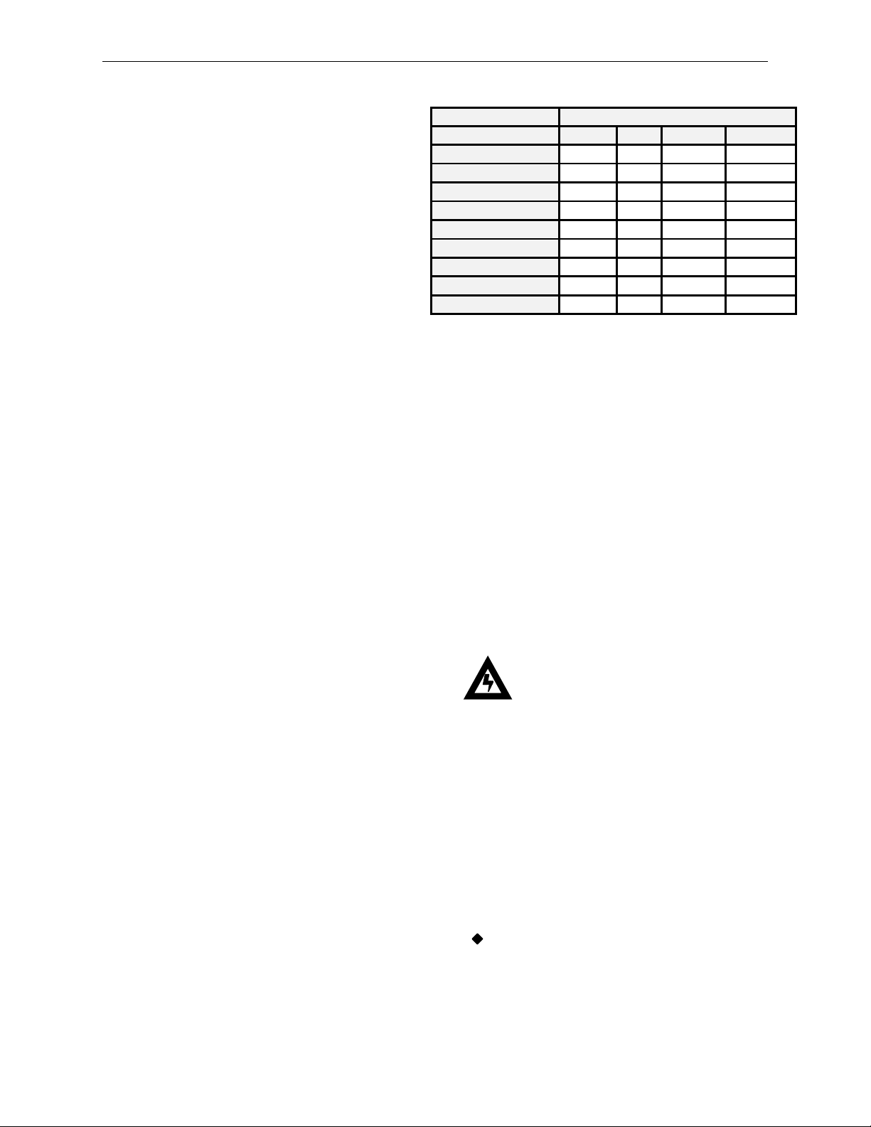
Accountability Information
All MIS data is stored as both resettable and nonresettable with the exception of Machine
Identification Number, Machine Serial Number,
Software Version Number, Number of MIS Resets,
Number of Machine Resets and Door Open History,
which are stored as non-resettable only. All vend
counters will roll over at 7 digits (9,999,999). All
cash counters will roll over at 8 digits including the
decimal point (999,999.99). Vend accounting (MIS)
is updated as shown in Table 1.
GPL 6500 V2.0 0108 4.02
Vend Type
Field
#VENDS
$VENDS (Sale Price)
#/PROD
$/PROD (Sale Price)
#/TESTVEND
# /FREE
$ /FREE
# /TOKEN
$ /TOKEN
Table 1: MIS Field Update Chart
X - Indicates which field is updated for a given
Shutdowns
There are 2 options available to shutdown the
Fusion machine.
1. The Fusion machine is capable of having timed
shut down periods. More information can be found in
the programming section Mode 51.
2. The control board on the Fusion machine can be
shutdown by creating a closed circuit between pin 3
& pin 4 on the service connecter P2. This shutdown
type will lock out selections entered into mode 32.
When in this shutdown type and a shutdown
selection is entered the display will show “Invalid
Selection” for 5 seconds or until a new selection key
is pressed.
Token Vend Testvend Freevend
X X
0 X
X X
0 X
X
X
X
X
X
vend type.
Caution: Do not apply Voltage to
these pins! Damage to the Board
will result!
DEX/UCS
The Fusion supports DEX/UCS Communications
Protocol - NAMA Vending Industry Data Retrieval
Standard. The machine will automatically recognize
the DEX/UCS device when it is plugged into the
control board and will recognize when the device
initiates the communication protocol. The
transmission/reception of data to the device will then
take place automatically. See the next page of this
manual for definitions of the DEX/UCS download
protocol.
See Page 5.31 for information regarding the
setting of a Serial Number, Machine ID and
Location ID.
Page 28

Operating System
ID4*2*1*0
# of positions to right of decimal pt*Country
(ITCC)*Currency in use
ID5*050510*122708
System Date
-
YYMMDD*Time
-
HHMM
ID7***APi
***Manufacturer Code
CB1*API33221144556699887*ST/130*0001
Control Board Serial Number*Model*Software revision
CA9*0*0
Value of Vends while in exact change
-
interval*Value of Vends while in exact change
-
historical
CA10*0*0
Value of all cash added since last reset*Value of all cash added since initialization
CA15*1225
Value
of coin tubes
BA1*29821563422*SPRINTR*504
Bill Validator Serial Number*Model*Software revision
DA1*0*0*0
Cashless 1 Serial Number*Model*Software revision
DA2*0*0*0*0
Cashless 1 Historical Vends*Historical Cash*Interval Vends*Interval Cash
DA4*0*0
His
torical Value credited to Cashless 1*Interval Value credited to Cashless 1
PA1*CAN
Can Sales Header
PA2*4294919762*550
Historical Vends
-
Cans*Historical Cash
-
Cans
PA1*110*50*110*0 (See Note 1)
Selection ID*Vend price*Product code*Spiral Count
Sales Selection 110
The MIS data stored by the machine for a DEX/UCS download is as follows:
DEX/UCS Output Definition
ID1*API74563219087456123*STXXX*0010*
98765432198765432**12345678901234567
VA1*1200*18*300*5*0*18*0*5 Total Sales Historical Amount*Total Vends Historical Count*Total Interval Sale Amount*Total Interval
VA2*0*2*0*0 Historic Value Test Vends*Historic Test Vends*Interval Value Test Vends*Interval Test Vends
VA3*0*0*0*0 Value –Free Vends Historical*Count -Free Vends Historical*Value -Free Vends Interval*Count -Free
TA2*0*0*0*0 Value -Token Vends Historical*Count -Token Vends Historical*Value -Token Vends Interval*Count -
CA1*0*0*0 Serial Number*Model*Software revision
CA2*1200*18*300*5 Total Cash Historical*Total Cash Vends Historical*Interval Cash*Interval Vends
CA3*350*0*150*2*1350*0*850*5*200*500 Interval cash received*Interval Cash to Cashbox*Interval Cash to tubes*Interval Value of
CA4*50*0*1150*1100 Interval cash dispensed*Interval cash dispensed manually*Historical cash dispensed*Historical cash
CA7*0*0*5*18 Interval Value cash discounts given*Historical Value cash discounts given*Interval Number cash
Machine S/N*Machine Model*Machine Revision*Location ID**Machine ID #
Vends*Historical Value of All Discounted Paid Vends*Historical count of All Discounted Paid
Vends*Interval Value of All Discounted Paid Vends*Interval Count of All Discounted Paid Vends
Vends Interval
Token Vends Interval
Bills*Historical Cash received*Historical Cash to Cashbox*Historical Cash to Tubes*Historical Value of
Bills*Interval Value of Bills
dispensed manually
discounts given*Historic Number cash discounts given
PA2*0*0*0*0 (See Note 1)
PA4*0 (See Note 1)
PA5*050510*122708 (See Note 1)
EA1*EGS*000000*000008*00 EGS(Door Opening History)*Date YYMMDD*Time HHMM*Duration (minutes)
EA2*EGS*1*4**1 EGS*Interval Door Openings*Historical Door Openings*Current Status 1 = Door open
EA1*EJB*000000*000008*00 EJB (Motor Errors)*Date YYMMDD*Time HHMM*Duration (minutes)
EA2*EJB*60*194**1 EJB*Interval Motor Errors*Historical Motor Errors**Current Status 1 = Motor Error exists
EA1*ELA*000000*000008*00 ELA (Product Delivery Errors*Date YYMMDD*Time HHMM*Duration (minutes)
EA2*ELA*0*0**0 ELA*Interval Product Delivery Errors*Historical Product Delivery Errors**Current Status 1 = Detector
EA1*EJH*000000*000008*00 EJH (Health Code Errors)*DateYYMMDD*Time HHMM**Duration (minutes)
EA2*EJH*0*0 EJH*Interval Health Code Errors*Historical Health Code Errors**Current Status 1 = Detector OK
EA1*OA1E*000000*000008*00 0A1E (Date & Time Resets)*Date YYMMDD*Time HHMM**Duration (minutes)
EA2*OA1E*0*0 OA1E*Interval Date & Time Resets*Historical Date & Time Resets**Current Status Always = 0
EA3*2********2*2 Number Of Reads With Reset Since Initialization********Number Of Reads Since Initialization*Number
EA4*000000*000008 (Initialization Timestamp)YYMMDD*hums
EA5*000000*000008 (Price Setting Timestamp)YYMMDD*hums
EA7*0*2 Power up/down cycles since last reset*Power up/down cycles since initialization
Historical Vends Selection 110*Historical Cash Selection 110*Interval Vends Selection 110*Interval
Historical Free Vends Selection 010
Date & Time of last vend for this selection
OK
of Resets since Initialization
GPL 6500 V2.0 0108 4.03
Page 29

Operating System
CA304
Value of Bills In Since Last Reset
-
all sources
CA305
Value of Cash In Since Initialization
-
all sources
CA308
Value of Bills In Si
nce Initialization
-
all sources
CA310
Value of Bills In Since Initialization
-
all sources
MA5606
Value of All Bills Dispensed or Moved from the Recycler Since Initialization
MA5608
Valu
e of All Bills Dispensed Manually from the Recycler Since Initialization
MA5610
Value of All Bills Manually Stacked from the Recycler Since Initialization
MA5701
Value of Coins in Coin Tubes
MA5702
Value of Bills in Recycler
MA5802
Value of
Bills to Recycler in Manual FILL Mode Since Initialization
DEX/UCS Output Definition
CA403 Value of Cash Dispensed Since Initialization
CA404 Value of Cash Manually Dispensed Since Initialization
CA1501 Value of Tube Contents
MA5508 Value of Bills to Stacker Since Initialization
MA5510 Value of Bills to Recycler Since Initialization
MA5603 Value of All Coins Dispensed Since Initialization
Note: PA1, PA2, PA4 and PA5 Fields repeat for each valid selection.
Table 2: DEX/UCS Information.
GPL 6500 V2.0 0108 4.04
Page 30
Programming
01 MOTOR DIDN’T HOME
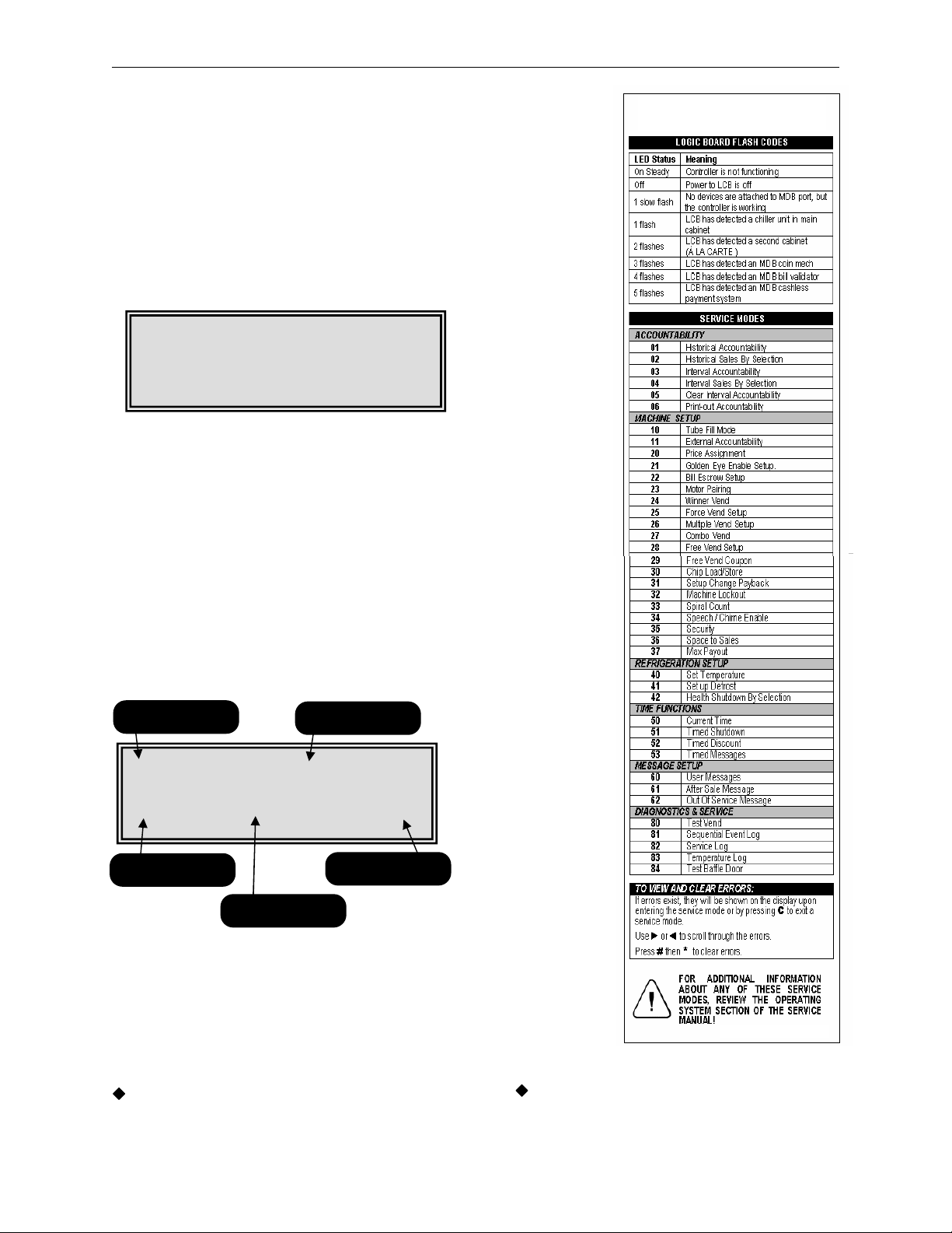
Service Modes
The table on the right side of this page is a copy of
the decal found on the left side of the barrier inside
the Ultra Flex machines. This decal provides a list of
the service modes described in the following pages.
Access to the Service Mode, is granted upon
opening of the main door. If a period of no activity
occurs for 5 minutes, the controller will automatically
revert to the Operate Mode. Entrance to the Service
Mode clears any current credit. If no errors are
present the following display will appear (Figure 13).
PRESS C FOR MODES
FIGURE 13: Initial Service Mode Screen
To enter the Service Modes (see Figure 15) press
the C key or use the numeric key pad to enter the
Service Mode number.
If errors are present the error reporting screen will
be displayed (see Figure 14). Use the ◄ and ►
keys to scroll through the errors listed. Press the #
key followed by the * key to clear the errors. To
enter the Service Modes (see Figure 15) press the C
key or use the numeric key pad to enter to the
Service Mode number.
Field A
112 08/22 12:00
Field C
FIGURE 14: Initial Service Mode Screen when
Field A is the sequential number of the error.
Field B is the error description field.
Field C is the motor number if applicable.
Field D is the date of the error.
Field E is the time of the error.
See the Troubleshooting Section of this
manual for specific information regarding the
errors being reported.
NO ERRORS
when no errors are present.
Field B
Field E
Field D
errors are present.
To coin test the machine with the door open
either press the Service Switch (see Figure 16)
or unplug the door switch from the control
board.
GPL 6500 V2.0 0108 5.01
Page 31

Programming
Figure 15 shows the first screen encountered after
pressing the C key in either of the previous two
screens (Figure 13 and Figure 14). Use the ◄ or ►
keys to scroll sequentially through the modes or use
the numeric key pad to enter the Service Mode
number.
Entering one of the Service Mode numbers shown
on the following pages allows you to access that
Service Mode. Example: entering 20 will take you
into the Price Assignment Mode.
Figure 16: Location of Service Switch.
Field A
HIST ACCOUNTABILITY
01 PUSH # TO ENTER
Field B
FIGURE 15: First Service Mode
Number Screen.
Field A is the mode name.
Field B is the mode number.
Field C is the mode entering instructions.
Use the ◄ or ► keys to scroll
sequentially through the mode
numbers.
Field C
GPL 6500 V2.0 0108 5.02
Page 32

Programming
Field C
is
the total value
field.
Mode 01 – Historical Accountability
Mode 01 is used to view the historical accountability.
To access this mode, press 01 on the numeric
keypad.
Pressing either the ◄ or ► key will sequence you
through the historical accountability fields in the
order shown in the table below. To exit this mode,
press the C key or press the Service Switch.
FIELD A
The display will show
HIST PAID SALES
#0000000 $0000000.00
HIST NUMBER TESTS
#0000000
HIST FREE VENDS
#0000000 $0000000.00
HIST CASH VENDS
#0000000 $0000000.00
HIST VALUE BILLS
$000000
HIST VALUE CASH
$0000000.00
HIST VALUE TUBE
$0000000.00
HIST VALUE BOX
$0000000.00
HIST VALUE DISP
$0000000.00
HIST VALUE MDISP
$0000000.00
HIST VALUE ECV
$0000000.00
VALUE TUBE COINS
$0000.00
HIST TOKEN VENDS
#0000000 $0000000.00
HIST CASHLESS VENDS
#0000000 $0000000.00
HIST CAN VENDS
#0000000 $0000000.00
HIST CAB 1 VENDS
#0000000 $0000000.00
HIST CAB 2 VENDS
#0000000 $0000000.00
GOLDEN EYE
REVISIONS
CAB1 00 CAB2 00
HIST NUMBER GE
#0000000
Table 4: Historical accountability fields.
GPL 6500 V2.0 0108 5.03
DESCRIPTION
Total Value of Sales
# of Test Vends
Free Vends
Cash Sale
Value of Bills Stacked
Value of Cash In
Value of Coins to
Tubes
Value of Coins
Routed to Cash Box
Value of Cash
Dispensed
Value of Cash
Manually Dispensed
Value of Exact
Change Vends
Current Value of
Coins in Tubes
Token Vends
# of Cashless Vends
Can Vends
Cab 1 Vends
Cab 2 Vends
PosiVend Software
Revision
# OF PosiVend Spiral
Turns
#XXXXXXX $XXXXXX.XX
indicates a vend counter. When the data field
begins with a $ sign this indicates a cash value.
Field A is the accountability name field.
Field B is the total vend count field.
When a data field begins with a # symbol this
Field A
SEE TABLE 4
Field B
Mode 01 – Historical Accountability
Field C
Page 33

Programming
Mode 02 – Historical by Selection
Mode 02 is used to view the historical accountability
by selection. To access this mode, press 02 on the
numeric keypad.
Pressing either the ◄ or ► key will sequence you
through the selections or use the numeric key pad to
enter a selection number into Field A. Field B shows
date and Field C shows you the time of the last vend
for the selection shown in Field A. Field D shows
you the number of vends and Field E shows you the
total dollar value of vends for the item in Field A. To
exit this mode, press the C
Switch.
All time based information is dependent upon
the clock on the control board being set
correctly, see Mode 50.
Mode 03 – Interval Accountability
Mode 03 is used to view the interval accountability.
To access this mode, press 03 on the numeric
keypad.
Pressing either the ◄ or ► key will sequence you
through the interval accountability fields in the order
shown in the table below. To exit this mode, press
the C key or press the Service Switch.
All interval data is reset to zero under the
following two conditions.
1. A successful DEX download is
performed, or
2. Mode 05 is used to clear the Interval
data.
This also applies to the Interval data in Modes 04
and 06.
GPL 6500 V2.0 0108 5.04
key or press the Service
Field A
H XXX MM/DD/YY HH:MM
#XXXXXXX $XXXXXX.XX
Field D
Mode 02 – Historical by Selection
Field A is the item number.
Field B is the date of the last vend for the
item in Field A.
Field C is the time of the last vend for the
item in Field A.
Field D is the number of vends for the
item in Field A
Field E is the historical dollar value of all
vends for the item in Field A.
Field A
#XXXXXXX $XXXXXX.XX
Field B
Mode 03 – Interval Accountability
Field A is the accountability name field.
Field B is the interval vend count field.
Field C is the interval dollar value field.
Field B
Field C
Field E
SEE TABLE 5
Field C
Page 34

Programming
Mode 04 – Interval by Selection
Mode 04 is used to view the interval accountability
by selection. To access this mode, press 04 on the
numeric keypad.
Pressing either the ◄ or ► key will sequence you
through the selections or use the numeric key pad to
enter a selection number into Field A. Field B shows
date and Field C shows you the time of the last vend
for the selection shown in Field A. Field D shows
you the number of vends and Field E shows you the
dollar value of vends for the item in Field A. To exit
this mode, press the C
Switch.
When the security option in Mode 35 is
enabled only Modes 01 through 04 will be
accessible without a password. Attempting to
access any other Mode will prompt the operator
to enter the correct password.
FIELD A
The display will show
INTR PAID SALES
#0000000 $0000000.00
INTR NUMBER TESTS
#0000000
INTR FREE VENDS
#0000000 $0000000.00
INTR CASH VENDS
#0000000 $0000000.00
INTR VALUE BILLS
$000000
INTR VALUE CASH
$0000000.00
INTR VALUE TUBE
$0000000.00
INTR VALUE BOX
$0000000.00
INTR VALUE DISP
$0000000.00
INTR VALUE MDISP
$0000000.00
INTR VALUE ECV
$0000000.00
VALUE TUBE COINS
$0000.00
INTR TOKEN VENDS
#0000000 $0000000.00
INTR CASHLESS VENDS
#0000000 $0000000.00
GOLDEN EYE
REVISIONS
CAB1 00 CAB2 00
INTR NUMBER GE
#0000000
Table 5: Interval accountability fields.
GPL 6500 V2.0 0108 5.05
key or press the Service
DESCRIPTION
Total Value of Sales
# of Test Vends
Free Vends
Cash Sale
Value of Bills
Stacked
Value of Cash In
Value of Coins to
Tubes
Value of Coins
Routed to Cash Box
Value of Cash
Dispensed
Value of Cash
Manually Dispensed
Value of Exact
Change Vends
Current Value of
Coins in Tubes
Token Vends
# of Cashless Vends
PosiVend Software
Revision
# OF PosiVend
Spiral Turns
Field A
I XXX MM/DD/YY HH:MM
#XXXXXXX $XXXXXX.XX
Field D
Mode 04 – Interval by Selection
Field A is the item number.
Field B is the date of the last vend for the
item in Field A.
Field C is the time of the last vend for the
item in Field A.
Field D is the number of vends for the
item in Field A
Field E is the dollar value of the vend for
the item in Field A.
Field B
Field C
Field E
Page 35

Programming
Mode 05 – Clear Interval Data
Mode 05 is used to clear the interval data. To
access this mode, press 05 on the numeric keypad.
Upon entering the display will show “CLEAR
INTERVAL DATA”. Pressing the # key followed by
the * key will clear all interval data. To exit this mode
without clearing the data, press the C key or press
the Service Switch.
Mode 06
Mode 06 is used to transmit the MIS information to a
printer. To access this mode, press 06 on the
numeric keypad.
Press the # key to send all historical and interval
accountability including data by selection. Use the *
key to send all historical and interval data but not
send the data by selection, for specific details of
what is included in each list see Table 6. To exit this
mode, press the C key or press the Service Switch.
Table 6 Notes
♦ An (H) at the end of the definition means
historical data.
♦ An (I) at the end of the definition means Interval
data.
♦ The column heading titled F is the full list.
♦ The column heading titled S is the short list.
♦ Fields highlighted in bold are repeated for each
valid selection in the machine.
See Page 5.31 for information regarding the
setting of a Serial Number, Machine id and
Location id.
GPL 6500 V2.0 0108 5.06
– Print out Accountability
Field A is the mode identification field.
Field B is the instruction field.
Field A shows the transmission
characteristics for the printer.
Field B is the short list download
instruction field.
Field C is the full list download instruction
field.
Field A
CLEAR INTERVAL DATA
PRESS # * TO CONFIRM
Field B
Mode 05 – Clear Interval Data
Field A
TRANSMIT 9600 N-8-1
* = SHORT # = FULL
Field B
Mode 06 – Print out Accountability.
Field C
Page 36

Programming
Table 6: MIS Definitions.
Mode 06 - Continued
Field Definition F S
ID101 Machine Serial # X X
ID102 Machine ID # X X
ID103 Machine Version # X X
ID104 Machine Location X X
ID106 Machine Asset # X X
ID501 System Date X X
ID502 System Time X X
ID703 Manufacturer Code X X
CB101 LCB Serial # X X
CB102 LCB ID # X X
CB103 LCB Software Version X X
ID401 Decimal Point Position X X
ID402 Country Code X X
ID403 Currency Code X X
VA101 Value of all Paid Sales (H) X X
VA102 Number of all Sales (H)_ X X
VA103 Value of all Paid Sales (I) X X
VA104 Number of all Sales (I) X X
VA105 Value of Discounted Sales (H) X X
VA106 Number of Discounted Sales (H) X X
VA107 Value of Discounted Sales (I) X X
VA108 Number of Discounted Sales (I) X X
VA201 Value of Test Vends (H) X X
VA202 Number of Test Vends (H) X X
VA203 Value of Test Vends (I) X X
VA204 Number of Test Vends (I) X X
VA301 Value of Free Vends (H) X X
VA302 Number of Free Vends (H) X X
VA303 Value of Free Vends (I) X X
VA304 Number of Free Vends (I) X X
BA101 Bill Validator Serial Number X X
BA102 Bill Validator ID Number X X
BA103 Bill Validator Software Version X X
CA101 Coin Changer Serial Number X X
CA102 Coin Changer ID Number X X
CA103 Coin Changer Software Version X X
CA201 Value of Cash Sales (H) X X
CA202 Number of Cash Sales (H) X X
CA203 Value of Cash Sales (I) X X
CA204 Number of Cash Sales (I) X X
CA308 Value of Bills Stacked (H) X X
CA304 Value of Bills Stacked (I) X X
CA305 Value of Cash in (H) X X
CA301 Value of Cash in (I) X X
CA307 Value of Coins to Tubes (H) X X
CA303 Value of Coins to Tubes (I) X X
CA306 Value of Cash to Cashbox (H) X X
CA302 Value of Cash to Cashbox (I) X X
CA3010 Value of Bills Stacked (H) X X
CA309 Value of Bills Stacked (I) X X
CA403 Value of Cash Dispensed (H) X X
CA401 Value of Cash Dispensed (I) X X
CA404
Value of Cash Manually Dispensed
(H)
X X
Field Definition F S
CA402
CA702 Value of Cash Dispensed (H) X X
CA701 Value of Cash Dispensed (I) X X
CA704 Number of Cash Dispensed (H) X X
CA703 Number of Cash Dispensed (I) X X
CA902 Value of Exact Change Vends (H) X X
CA901 Value of Exact Change Vends (I) X X
CA1002 Tube Fill Value (H) X X
CA1001 Tube Fill Value (I) X X
CA1501 Current Value of Coins in Tubes (H) X X
MA501 Combo Vend Header X X
MA502
MA504
MA503 Number of Combo Vends (H) X X
MA505 Number of Combo Vends (I) X X
MA502 Value of Winner Vends (H) X X
MA504 Value of Winner Vends (I) X X
MA503 Number of Winner Vends (H) X X
MA505 Number of Winner Vends (I) X X
TA202 Number of Token Vends (H) X X
TA204 Number of Token Vends (I) X X
TA201 Value of Token Vends (H) X X
TA203 Value of Token Vends (I) X X
DA101 Cashless Serial Number X X
DA102 Cashless ID Number X X
DA103 Cashless Software Version Number X X
DA201 Value of Cashless Vends (H) X X
DA203 Value of Cashless Vends (I) X X
DA202 Number of Cashless Vends (H) X X
DA204 Number of Cashless Vends (I) X X
PA101 Can X X
PA202 Value of Can Vends (H) X X
PA201 Number of Can Vends (H) X X
PA103 Selection Number Header X X
PA102 Price X X
PA107 Selection Status X X
PA202 Value of Vends by Selection (H) X
PA204 Value of Vends by Selection (I) X
PA201 Number of Vends by Selection (H) X
PA203 Number of Vends By Selection (I) X
PA401
PA501 Time and Date of Last Vend (H) X
PA502 Time and Date of Last Vend (I) X
LE101 Loop Trailer X X
EA301 Number of Reads with Reset X X
EA309 Number of Reads X X
EA3010 Number of MIS Resets X X
EA401 Date of Initialization X X
Value of Cash Manually Dispensed
(I)
Value of Discount for Combo Vends
(H)
Value of Discount for Combo Vends
(I)
Number of Free Vends by Selection
(H)
EA402 Time of Initialization X X
* Items highlighted in bold repeat for each valid
selection.
X X
X X
X X
X
GPL 6500 V2.0 0108 5.07
Page 37

Programming
Mode 10 – Tube Fill
Mode 10 allows you to fill the coin mech and the
logic board will count the money as it goes in and
continually track the coin mech inventory. This is the
count the board uses when you choose tube leveling
as the payout type in Mode 31.To access this mode,
press 10 on the numeric keypad.
Upon entering the tube fill mode the controller will
display the current status of the coin tubes. As coins
are inserted into the top of the changer, the display
will show the tube the coin was saved to in Field A,
the value of all coins in that tube in Field B and the
total dollar amount of coins in the changer in Field
C. Coins may be dispensed by using the switches
on the coin mech. To exit this mode, press the C
key or press the Service Switch.
Before using the machine for the first time,
the coin mech must have a minimum of $5 in the
coin tubes to permit the acceptance of bills.
Mode 11 – External Accountability
Mode 11 is used to permit you or your customer, via
a password, to review the total vend count and total
cash accepted by the machine. To access this
mode, press 11 on the numeric keypad.
Pressing either the ◄ or ► key will allow you to
toggle back and forth between the fields.
Upon entering the external accountability setup
mode, the display will show the current external
accountability state. Use the numeric key pad to set
a 4 digit security code in field A. Toggle to field B
use the # key to turn the external accountability
function on (Y) or off (N). To exit this mode, press
key or press the Service Switch.
the C
Note
♦ If enabled, instruct the customer/contact to
enter 8 and then the 4 digit code. The display
will show the total vend count in Field C and the
total value in Field D.
Field A
Field B Field C
TUBE 0 .00 ∑ .00
INSERT / DISPENSE COIN
Field A is the tube number the coin was
saved to.
Field B is the value of coins in the tube
identified in Field A.
Field C is the total value of coins in the
changer.
Mode 10 – Tube Fill
Field A
Field B
ACCOUNTING 81111 N
Mode 11 – External Accountability
Field A is the security code field.
Field B is the feature on/off field.
Field C
Field D
# XXXXXXX $XXXXXX.XX
HIST PAID SALES
Mode 11 – Customer Viewable Data
Field C is the total vend count field.
Field D is the total value field.
GPL 6500 V2.0 0108 5.08
Page 38

Programming
Mode 20 – Price Assignment
Mode 20 is used to assign the standard price for all
selections in the machine. To access this mode,
press 20 on the numeric keypad.
Pressing either the ◄ or ► key will allow you to
toggle back and forth between the fields.
Use the numeric keypad to enter the price in Field A,
then toggle to Field B to assign the current price to a
selection. To exit this mode, press the C
press the Service Switch.
Note
♦ The maximum price allowed is $99.99.
Special Actions
♦ Setting selections with a blank price disables
that selection which means DEX information will
no longer be transferred or displayed for items
disabled in this way. The blank price is set by
depressing the # Key.
♦ The * key can be used as a wildcard in Field B
to set entire rows (12*) or the entire machine
(1**).
♦ After assigning the prices, make sure you adjust
the scrolling price tabs to reflect the current or
new price.
You can use the ◄ or ► key while in the
operate mode with the door open to check the
prices in the machine.
Mode 21
Mode 21 is used to set up the PosiVend Guarantee
Delivery System. To access this mode, press 21 on
the numeric key pad.
– PosiVend Enable Setup
Upon entering the PosiVend setup mode, the display
will show the current PosiVend state in Field A.
Toggle between the available options in Field A by
using the # key. Each selection affected by the
setting in Field A are shown in sequence in Field B,
use the ◄ or ► key to scroll through these
selections. Use the numeric key pad to add
selections in Field B. To remove a selection from
Field B, press the # key while the selection number
is displayed. To exit this mode, press the C key or
press the Service Switch.
GPL 6500 V2.0 0108 5.09
key or
GOLDEN EYE DROP
SELECTION 100
PRICE .50
SELECTION 12*
Mode 20 – Price Assignment
Field A is the price setting field.
Field B is the selection assignment field.
Mode 21 – PosiVend Enable Setup
Field A is the PosiVend option setting
field.
Field B is the selection assignment field.
Field A
Field B
Field A
Field B
Page 39

Programming
Mode 21 - Continued
Available Options
Drop – The motor will stop as soon as the product is
detected after the first complete revolution.
Home – The motor will home before stopping.
Off – PosiVend is disabled, the motor will stop as
soon as it reaches home whether a product has
been delivered or not.
See page 3.04 for a complete description of the
function of the PosiVend Guaranteed Delivery
System.
Special Actions
♦ The * key may be used as a wildcard to set
the entire rows (12*) or the entire machine
(1**).
♦ To delete all selections press the # key then
the * key in sequence.
To home motors left off home in the DROP
mode, open the door and press the C key, then
close the door.
Mode 22 – Bill Escrow Setup
Mode 22 is used to set the bill escrow option. To
access this mode, press 22 on the numeric keypad.
Upon entering the bill escrow set up mode, the
display will show the current bill escrow state in Field
A. Use the # key to toggle between the available
options in Field A. To exit this mode, press the C
key or press the Service Switch.
Available options
First – The machine will hold the first bill deposited
in escrow until a vend is initiated. Once a vend is
initiated the bill must be stacked before the product
will be dispensed. In this mode only one bill will be
accepted. If the coin return is depressed, the bill will
be returned to the customer.
Last – The machine will accept bills to the highest
vend price. If the coin return is depressed the last
bill inserted will be returned and all previous bills
inserted will be returned in change.
Off – All bills accepted will be stacked immediately.
If the coin return is depressed, change will be paid
back.
GPL 6500 V2.0 0108 5.10
ESCROW LAST
Field A is the escrow setting field.
Field A
Mode 22 – Bill Escrow Setup
Page 40

Programming
Mode 23 – Motor Pairing
Mode 23 is used to pair an even numbered motor
with the next sequential odd numbered motor. To
access this mode, press 23 on the numeric keypad.
Upon entering the motor pairing set up mode, the
display will show “100 PAIRED TO”. Use the
numeric key pad to enter the even numbered motor
to be paired in Field A. The odd numbered motor
next in sequence will automatically appear in Field
B. Use the ◄ or ► keys to scroll through the list of
paired motors. Use the # key to remove a previously
paired combo. To exit this mode, press the C
press the Service Switch.
Notes
♦ Only motors in the same row of a machine may
be paired.
♦ All pricing, discounting and vending options are
set using the selection number of the left motor
in the pair.
♦ Any even number motor may be paired to the
next odd numbered motor in sequence. (e.g.
110 will always be paired with 111, 112 with
113, etc)
Mode 24 – Winner Mode
Mode 24 is used to set the frequency that free items
will be awarded during cash vends only. To access
this mode, press 24 on the numeric key pad.
Pressing either the ◄ or ► key will allow you to
toggle back and forth between the fields.
Upon entering the Winner Mode, the display will
show the current winner setting in Field A. Use the
numeric key pad to enter the number of vends
between winners up to 9999, then toggle to Field B,
use the # key to turn the Winner Mode on (Y) or off
(N). To exit this mode, press the C
Service Switch.
When a customer wins, the credit will be returned
the beeper will sound 5 times and the display will
show “WE HAVE A WINNER!!”.
Notes
♦ Vends made while on free vend, test vend or
the second vend of a combo vend are not
counted for the purpose of determining the
winner.
♦ Setting the number to 0000 will result in every
vend being a winner.
GPL 6500 V2.0 0108 5.11
key or press the
key or
Field A is the number of vends between
winners.
Field B is the winner on/off field.
Field A Field B
100 PAIRED TO XYZ
PRESS # TO REMOVE
Field C
Mode 23 – Motor Pairing
Field A is the even motor number to be
paired.
Field B is the odd number motor to be
paired this number will automatically
appear once a selection is entered in field
A.
Field C is the instructions to remove a
previously set motor pair.
Field A
WINNER XXXX N
Field B
Mode 24 – Winner Mode
Page 41

Programming
Mode 25 – Force Vend Setup
Mode 25 is used to set the force vend option. To
access this mode, then press 25 on the numeric
keypad.
Upon entering the force vend mode, the display will
show the current force vend state. Use the # key to
toggle between on and off in Field A. To exit this
mode, press the C key or press the Service Switch.
Available options
On – The customer must purchase an item before
any credit will be returned.
Off – The customer may receive their money back
at any time.
Notes
♦ Force vend does not apply to the use of debit
cards or to bills held in escrow, only to non-tube
coins.
Mode 26 –Multi-vend Setup
Mode 26 is used to set the multi-vend option. Multivend allows the customer to make an additional
selection using the change amount due from the
prior vend. To access this mode, 26 on the numeric
keypad.
Pressing either the ◄ or ► key will allow you to
toggle back and forth between the fields.
Upon entering the multi-vend mode the display will
show the current multi-vend state. Use the # key to
toggle between on and off, then toggle to Field B to
change the time-out setting, the default setting is 30
seconds if a larger time-out setting is desired use
the numeric key pad to enter the larger time. To exit
this mode, press the C
Switch.
Available options
On – Allows customer to make additional selections
as long as sufficient credit exists to purchase the
lowest priced item in the machine. The customer
may establish additional credit at any time when in
this mode. If the customer presses the coin return
lever, or the amount of available credit drops below
the lowest price in the machine or the time-out
expires, change is returned regardless of the state
of multi-vend.
Off – Change will be returned immediately after the
sale.
key or press the Service
FORCE VEND ON
Mode 25 – Force Vend Setup
Field A is the force vend on/off field.
MULTI-VEND ON
SECONDS 030
Mode 26 – Multi-vend Setup
Field A is the multi-vend on/off field.
Field B is the time-out field; the default
time is 30 seconds. The available range
is 5 to 90 seconds.
Field A
Field A
Field B
GPL 6500 V2.0 0108 5.12
Page 42

Programming
COMBO VEND N TIME SS
field.
Mode 27 – Combo Vend Setup
Mode 27 is used to set the combo vend feature. A
combo vend allows you to set up a selection to be
offered in conjunction with another selection. To
access this mode, press 27 on the numeric keypad.
Pressing either the ◄ or ► key will allow you to
toggle back and forth between the fields.
Upon entering the combo vend mode the display will
show the current combo vend state. Use the # key
to toggle between on (Y) and off (N) in Field A, then
toggle to Field B use the numeric key pad to set the
time out value in seconds. The time-out value is the
number of seconds the customer has to add
additional credit in order to purchase a combo vend
combination. Then toggle to Field C
to set a unique number for the combination, this
number is settable from 0 to 9 allowing for 10
different combinations at any 1 time. Then toggle to
Field D and use the numeric key pad to set the item
that is to be selected by the customer, then toggle to
Field E and use the numeric key pad to select the
item to be offered in combination with the customer
selected item. Then toggle to Field F and use the
numeric key pad to set the discount amount of the
combination item. Then toggle to Field G and use
the # key turn the selected combination vend on (Y)
or off (N). To exit this mode, press the C key or
press the Service Switch.
Notes
♦ Setting the discount amount in Field F to $99.99
will allow the discounted item to be vended for
free.
♦ Wild carding with the * key is not allowed in the
combo vend.
♦ When combo vend is active, the display will
scroll the message “FEATURED ITEM *** BUY
XXX AND SAVE $ ON YYY”.
Mode 28
Mode 28 is used to set the free vend option. To
access this mode, press 28 on the numeric keypad.
Upon entering the free vend option mode the display
will show the current free vend state. Use the # key
to toggle the free vend on or off in Field A. To exit
this mode, press the C key or press the Service
Switch.
Note
♦ Free vend applies to the entire machine.
– Free Vend Option
use the # key
Field A
Field B
00 XXX-YYY .00N
Field D
Field C
Mode 27 – Combo Vend Setup
Field A is the global combo vend on/off
field.
Field B is the time-out field measured in
seconds.
Field C is the number assigned to the
combo vend.
Field D is the item selected by the
customer.
Field E is the item to be vended in
combination with the customer selected
item.
Field F is the discount amount of the
combination item.
Field G allows the user to turn the
combination item on or off, but leave the
rest of the combination vends in use.
Field E
Field A
Field F
Field G
FREE VEND ON
Mode 28 – Free Vend Option
Field A is the free vend option on/off
GPL 6500 V2.0 0108 5.13
Page 43

Programming
Field C
is the upload from
CHIP
function.
Mode 29 – Free Vend Coupon
Mode 29 is used to set the free vend coupon or
token option. To access this mode, press 29 on the
numeric keypad.
Upon entering the free vend coupon mode the
display will show Free Vend Coupon XXX in Field A,
where XXX is the selection enabled for the free vend
coupon. Each selection enabled for the free vend
coupon is shown in sequence in Field A by
depressing the ◄ or ► key. Use the numeric key
pad to add selections. To remove a selection, press
the # key while the selection number is displayed.
To exit this mode, press the C
Service Switch.
Special Actions
♦ The * key may be used as a wildcard to set
entire rows (12*) or the entire machine (1**).
Mode 30 – Chip Retrieve/Store Mode
Mode 30 is used to retrieve or store information from
the touch memory button (CHIP). To access this
mode, press 30 on the numeric keypad.
To store all programmable information to CHIP
press the * key as shown in Field B. To upload
information previously stored on a CHIP press the #
key as shown in field C. To exit this mode, press the
C key or press the Service Switch.
To make sure that the information being
transferred from the CHIP is compatible the
software revision numbers will be compared
before the transfer. If the version on the CHIP is
not compatible the transfer is canceled and the
display will show “CHIP NOT COMPATIBLE”.
key or press the
FREE VEND COUPON XXX
PRESS # TO REMOVE
Field B
Mode 29 – Free Vend Coupon
Field A is the selection enabled field.
Field B is the selection remove field.
Field A
Field A
CHIP STORE/RETRIEVE
* STORE # RETRIEVE
Field B Field C
Mode 30 – Chip Retrieve/Store Mode
Field A is the name of the mode.
Field B is the download to CHIP function.
GPL 6500 V2.0 0108 5.14
Page 44

Programming
Mode 31 – Change Payback Type
Mode 31 is used to set the change payback option.
To access this mode, press 31 on the numeric
keypad.
Upon entering the change payback mode, the
display will show the current change payback state
in Field A. Use the # key to toggle through the
available options. To exit this mode, press the C key
or press the Service Switch.
Available options
LEAST – The least amount of coins will be paid
back.
LVL3 – The coin changer makes the payback
decision based on how much money it thinks is in
each tube. You should use the “Tube Fill” menu item
(Mode 10) when you use this option.
Mode 32 – Selection Lockout
Mode 32 is used to lock selections from use in
conjunction with an external switch. To access this
mode, press 32 on the numeric keypad.
Upon entering the lockout mode the display will
show LOCK SELECTION XXX in Field A. Where
XXX is the selection enabled for lock out. Use the ◄
or ► key to scroll through each selection affected by
the lockout. Use the numeric key pad to add
selections. Use the # key while the selection number
is displayed to remove selections. To exit this mode,
press the C
Special actions
♦ The * key may be used as a wildcard.
♦ If all selections are disabled the lights will turn
off and no money will be accepted.
Note
♦ The mechanical lockout of selections is done
by adding an external key switch or other
switch across pins P2-3 & P2-4 on the logic
board.
♦ The machine will not function properly in
shutdown when the door is open. The machine
must not have the shut down switch active
while the door is open.
key or press the Service Switch.
Caution: Never apply voltage to
these pins.
CHANGE PAYBACK LEAST
Field A is the payback option selection
field.
LOCK SELECTION XXX
PRESS # TO REMOVE
Field A is the selection disable field.
Field B is the selection remove field.
Field A
Mode 31 – Change Payback Type
Field A
Field B
Mode 32 – Selection Lockout
GPL 6500 V2.0 0108 5.15
Page 45

Programming
Mode 33 – Set Spiral Count
Mode 33 is used to set the Spiral Count. Spiral
Count allows you to program the number of spaces
in each spiral. When a selection has vended all
product out of the individual spiral, the display will
show ‘SOLD OUT”. To access this mode, press 33
on the numeric keypad.
Pressing either the ◄ or ► key will allow you to
toggle back and forth between the fields.
Upon entering the set spiral count mode the
controller will display SPIRAL CNT OFF/ON in Field
A. Use the # key to toggle between OFF/ON. If Field
A is set to off no further action is needed.
If Field A is set to ON, Toggle to Field C and use the
numeric key pad to enter the spiral count. Then
toggle back to Field B and enter the selection
numbers that correspond to the spiral count set in
Field C. Repeat the above steps for each selection.
To exit this mode, press the C
Service Switch.
When Spiral Count is ON (Field A), each time the
main cabinet door is opened, the display will prompt
“STOCK MACHINE –Y”. Pressing the # key with the
Y showing will reset the spiral counts. Closing the
door without pressing the # key, the sold out status
of each spiral remains.
Special actions
♦ The * key can be used as a wildcard in Field B
to set entire rows (12*) or the entire machine
(1**).
♦ To disable a selection from spiral count set Field
C to 0.
Note
♦ If this function is enabled, route service
personnel must be instructed in its correct
operation. Failure to correctly reset the counts
will result in a full machine from vending
properly.
key or press the
SPIRAL CNT OFF
SELECTION XXX CNT 00
Field A is the spiral count on/off field.
Field B is the item selection field.
Field C is the spiral count field.
Field A
Field B
Mode 33 – Set Spiral Count
Field C
GPL 6500 V2.0 0108 5.16
Page 46

Programming
Mode 34 – Speech / Chime
Mode 34 is used to set the Speech/Chime options.
To access this mode, press 34 on the numeric
keypad.
Pressing either the ◄ or ► key will allow you to
toggle back and forth between the fields.
Upon entering the speech/chime options mode, the
controller will display the current SPEECH setting in
field A and the current CHIME setting in Field B.
The # key is used to toggle between on and off for
each field. To exit this mode, press the C
press the Service Switch.
Notes
♦ Turning the chime off will disable the beep from
sounding in all conditions, except for the health
code warning set in Mode 42.
♦ When speech is on, all messages in the service
mode will be transmitted via the DEX port for
use with an audio interface.
♦ When speech is on, the DEX/UCS port can no
longer be used for any other communication.
Mode 35 – Security
Mode 35 is used to set the Security options. To
access this mode, press 35 on the numeric keypad.
Pressing either the ◄ or ► key will allow you to
toggle back and forth between the fields.
Upon entering the security mode, the current
security settings will be displayed. Use the numeric
key pad to set the desired security code in Field A,
then toggle to Field B, use the # key to toggle
between on (Y) and off (N). To exit this mode, press
key or press the Service Switch.
the C
With the security code, the service person will only
be allowed access to Modes 01 to 04. Trying to
enter any other modes will change the display to
“ENTER SECURITY CODE”. Once the proper code
has been entered all modes in the machine will be
accessible until the service mode is exited.
Note
♦ Factory default settings are off (N) and a
security code of 1111.
Once the service mode as been exited, the
code must be re-entered to access Modes 05
through 84.
key or
CHIME ON
Field A is the speech option field.
Field B is the chime option field.
SECURITY CODE 1111 N
Field A is the security code entry field.
Field B is the security on/off field.
Field A
SPEECH OFF
Field B
Mode 34 – Speech/Chime
Field A
Field B
Mode 35 - Security
GPL 6500 V2.0 0108 5.17
Page 47

Programming
Mode 36 – Space to Sales
Mode 36 is used to set two columns to run together
in a Space to Sales manner. To access this mode,
press 36 on the numeric keypad.
Pressing either the ◄ or ► key will allow you to
toggle back and forth between the fields.
Upon entering the Space to Sales mode, the display
will show the current Space to Sales settings. Use
the # key in Field A to turn the Space to Sales
feature on (Y) or off (N). Toggle to Field B and use
the # key to set a unique number for the space to
sales combination. This number is settable from 0 to
9 allowing for 10 different Space to Sales
combinations at any one time. Toggle to Field C and
use the numeric key pad to set the first item number
to be vended in a space to sales manner, then
toggle to Field D and use the numeric key pad to set
the second item number to be vended in a space to
sales manner. Toggle to Field E, and use the # key
to turn the selection numbers set in Field B to on (Y)
or off (N). To exit this mode, press the C
press the Service Switch.
Space to sales allows you to program two
selection spirals to operate as one in an
alternating method. For example if selection 110
is entered into Field C and selection 112 is
entered into Field D, every time selections 110 or
112 are selected the product will be vended from
spiral 110 one time and 112 the next time. It is
important that any selections enabled in this
mode contain the same product. The goal of
space to sales is to increase the capacity of an
individual item while preventing the inevitable
empty spiral from occurring on a fast moving
product.
Mode 37
Mode 37 is used to set the Maximum Payout
options. To access this mode, press 37 on the
numeric keypad.
Pressing either the ◄ or ► key will allow you to
toggle back and forth between the fields.
Upon entering the maximum payout mode, the
controller will display the current max payout setting.
Toggle to Field A use the numeric key pad to set
the maximum value of coins to be returned, then
toggle to Field B and use the # key to turn on (Y) or
off (N) the option. To exit this mode, press the C key
or press the Service Switch.
Note
– Set Max Payout Mode
♦ When turned on (Y), if the credit after the sale is
greater than the Max Payout set point in Field A,
the machine will go into an automatic multi-vend
(mode 26).
GPL 6500 V2.0 0108 5.18
key or
priced identically.
SPACE TO SALES N
00 SELECTS 000-000 N
Field B
Field C
Mode 36 – Space to Sales
Field A is the space to sales on/off field.
Field B is the product type number field.
Field C is the first selection setting field.
Field D is the second selection setting
field.
Field E is the product type on/off field
Caution – Space to Sales items must be
Field A
MAX PAYOUT 99.99 N
Mode 37 – Set Max Payout
Field A is the maximum coin payout field.
Field B is the maximum coin payout on/
off field.
Field A
Field D
Field E
Field B
Page 48

Programming
Mode 40 – Set Temperature
Mode 40 is used to set the Temperature of the
cabinet(s). To access this mode, press 40 on the
numeric keypad.
Pressing either the ◄ or ► key will allow you to
toggle back and forth between the fields.
Upon entering mode 40, the display will show the
current temperature range setting. Field A is the
cabinet selection field, use the # key to choose
between 1 (cabinet 1) or 2 (cabinet 2). Toggle to
Field B to choose the temperature range option see below for the available options. Then toggle to
Field C to set the temperature for the chilled cabinet.
Use the 1 key to raise or the 2 key to lower the
temperature. Then toggle to Field E; use the # key
to choose between Fahrenheit (F) and Celsius (C)
temperature scales. To exit this mode, press the C
key or press the Service Switch.
Field B Temperature Range Options
AMBIENT – No temperature control. Field C will
show ------ F.
ZONE – The target temperature in Field C for each
zone in the machine is settable from +36° to +80° F
(4° to 21°C). This setting is only available if Field A
is set to cabinet 1, and should only be used when
selling non-perishable products. See page 2.02 for
additional information.
FOOD – The target temperature in Field C is fixed at
+36° F (2°C). This setting is used when the whole
cabinet or a portion of it contains perishable product.
When used in a GPL6500 with a barrier, shelves
located lower than the barrier must be enabled for
Health Code in Mode 42 – see page 5.20
FROZEN – The target temperature range in Field C
is settable from -15° to +10° F (-12° to -26°C) – Only
applies to an external cabinet (AP960 or AP320)
All temperature ranges have a + or – range of
3° F (2°C).
The temperature inside the machine can be
viewed from the outside by pressing and
holding the * key for °F or # key for °C.
GPL 6500 V2.0 0108 5.19
All items located above the barrier
assembly must be non-perishable!
Field A
Field B
CAB 1 ZONE L-- / H-- F
1 = TEMP UP 2 = TEMP DOWN
Field F
Mode 40 – Set Temperature for Cabinet 1
Field A is the cabinet selection field.
Field B is the temperature range selection field.
Field C is the temperature setting field for the
cabinet in the GPL6500.
Field D is only used on a dual zone machine, and
is not used in the GPL6500
Field E is the temperature scale field, F for
Fahrenheit or C for Celsius.
Field F is the instructions for raising and lowering
the temperature.
Field B
Field A
CAB 2 FROZEN -10 F
1 = TEMP UP 2 = TEMP DOWN
Field F
Mode 40 – Set Temperature for Cabinet 2
Field A is the cabinet selection field.
Field B is the temperature range selection field.
Field C is the temperature setting field. The
default setting for frozen is -10°F.
Field D is the temperature scale field, F for
Fahrenheit or C for Celsius.
Field F is the instructions for raising and
lowering the temperature.
Field C Field E
Field D
Field E
Field C
Page 49

Programming
Mode 41 – Defrost
Used on Models 320/960 only!
Mode 41 is used to set the Defrost schedule and to
start a Manual Defrost on 320/960 cabinets(s) only.
The defrost on the Fusion is automatic; for more
information on the Fusion defrost refer to the
refrigeration process page 2.02. To access this
mode, press 41 on the numeric keypad.
Pressing either the ◄ or ► key will allow you to
toggle back and forth between the fields.
Upon entering the Defrost setup mode, the display
will show the current defrost settings. Field A is the
cabinet selection field, use the # key to choose
between cabinet 1 (1) or cabinet 2 (2). Then toggle
to Field B, use the # key to set the defrost start time,
in the 24 hour format. Then toggle to Field C, use
the # key to choose between 6 or 8 hour time
intervals between defrosting. To start an immediate
defrost push the * key, the display will show “Defrost
Starts in 2 Minutes”. To exit this mode, press the C
key or press the Service Switch.
Mode 42 – Health Shutdown
Mode 42 is used to set the health shutdown options
for the cabinet(s). To access this mode, press 42 on
the numeric keypad.
Pressing either the ◄ or ► key will allow you to
toggle back and forth between the fields.
Upon entering the health shutdown mode, the
display will show the current health shutdown state.
Use the numeric key pad to enter the selection
numbers to be “health controlled” in Field A. Toggle
to Field B, use the # key to turn the health shutdown
on or off for the selected items. Repeat the above
steps for each selection. If you would like a chime to
sound when a health shutdown has occurred toggle
to Field C, use the # key to turn the chime on or off.
To exit this mode, press the C
Service Switch.
Special actions
♦ The * key can be used as a wildcard in Field A
to set entire rows (12*) or the entire machine
(1**).
If shelf is out of order due to health code, no
message is posted until a selection is made.
Once selection is made the display will say
“Make Another Selection”.
If the machine detects a Health Code error
and the chime feature is ON the control board
will sound a double beep every 30 seconds until
the Health Code error is corrected.
GPL 6500 V2.0 0108 5.20
key or press the
Field A
CAB 1 06:00 AT 6 HRS
PUSH * TO DEFROST
Field A is the cabinet selection field.
Field B is the time in the 24 hour format
to start the defrost cycle.
Field C is the interval in hours between
each defrost cycle settable to 6 or 8.
Field D is the information to start an
immediate defrost cycle.
Field A
HEALTH XYZ OFF
Mode 42 – Health Shutdown
Field A is the item selection field.
Field B is the health shutdown on/off
field.
Field C is used to turn on/off the health
shutdown notification chime.
Field B
Field D
Mode 41 - Defrost
CHIME OFF
Field C
Field C
Field B
Page 50

Programming
Mode 50 – Current Time
Mode 50 is used to set the current time date, date
format and daylight saving options. To access this
mode, press 50 on the numeric keypad.
Pressing either the ◄ or ► key will allow you to
toggle back and forth between the fields.
Upon entering the Current Time mode, the display
will show the current time (in 24 hour military time)
and date settings. Use the numeric key pad to
change the hour setting in Field A, then toggle to
Field B and use the numeric key pad to set the
minutes. Press the # key to set the time. Toggle to
Field C, use the numeric key pad to set the month,
then toggle to Field D, use the numeric key pad to
set the day, then toggle to Field E, use the numeric
key pad to set the year. Use the # key to save the
date. Toggle to Field F; use the # key to choose the
date format from the available options shown below.
Toggle to Field G to change the daylight savings
time zone setting using the available options shown
below. To exit this mode, press the C
the Service Switch.
You must press the # key each time to save
any changes to the time or date!
Field F available options
MONTH/DAY – This option will show the date in the
Month/Day/Year format (mmddyy).
DAY/MONTH – This option will show the date in the
Day/Month/Year format (ddmmyy).
Field G available options
OFF – Does not follow daylight savings time.
N.AMER – Will automatically adjust to North
American daylight savings time with a 1 hour
increase on the 2nd Sunday in March and a 1 hour
decrease the 2nd Sunday in November.
UK/EUR – Will automatically adjust to European
daylight savings time with a 1 hour increase on the
last Sunday in March and a 1 hour decrease on the
last Sunday in October.
AUSLIA – Will automatically adjust to Australian
daylight savings time with a 1 hour increase on the
last Sunday in October and a 1 hour decrease on
the last Sunday in March.
North American Daylight Savings Time was
changed in revision 20 software to follow the
new daylight savings times enacted in 2007.
key or press
TIME 00:00 00/00/00
MONTH/DAY DST N. AMER
Field A is the hour setting field (24 hour
military time).
Field B is the minute setting field.
Field C is the month setting field.
Field D is the day setting field.
Field E is the year setting field.
Field F is the date format field.
Field G is the daylight savings selection
field.
Field B Field D
Field F
Mode 50 – Current Time
It is recommended that the
battery be replaced every 5
years.
Field G
Field E Field A Field C
GPL 6500 V2.0 0108 5.21
Page 51

Programming
Use of low energy or total shutdown
in any machine with perishable
Mode 51 – Timed Shutdown
Mode 51 is used to set timed machine shutdown
periods. The shutdown periods affect the ability of
the machine to vend and the appearance of the
machine. To access this mode, press 51 on the
numeric keypad.
Pressing either the ◄ or ► key will allow you to
toggle back and forth between the fields.
Upon entering the timed shutdown mode, the display
will show the current shutdown setting. Use the #
key in Field A to set the shutdown period number;
this number may be set from 1 to 4 allowing for up to
4 different shutdown time periods per week. Toggle
to Field B using the numeric key pad set the
beginning hour then toggle to Field C and set the
beginning minute (using 24 hour military time).
Toggle to Field D using the numeric key pad set the
ending hour then toggle to Field E to set the ending
minute (using 24 hour military time). Toggle to Field
F use the ◄ or ► keys to scroll between the days of
the week, choosing which days the shutdown will
occur on, use the # key to turn the days on
(UPPERCASE) or off (lowercase). Toggle to Field
G press the # key to reach screen 2. Field A on
screen 2 references Field A on Screen 1 and should
not be changed. Toggle to Field H use the # key to
turn the shut down period on (Y) or off (N). Toggle to
Field I use the # key to set the shutdown type from
the available options shown below.
Field I available options
LIGHTS OFF – this option is used to shut down the
lights only. The machine will function in all other
ways.
VEND OFF – this option shuts down the lights,
disables vending by selection and if all selections
are disabled credit acceptance will also be disabled .
LOW ENERGY – this option will shut down the
lights, vending will be allowed. In cabinets without
health control enabled the temperature will be
allowed to rise 5 degrees above the set point during
the shut down period.
TOT SHTDWN – this option will shut down the
lights, compressor (in non health control machines),
vending, credit acceptance and the display.
Toggle to Field J use the numeric key pad to enter
the selection number the shutdown applies to,
toggle to Field K and use the # key to change the N
to Y, then toggle back to Field J and enter the
remaining selections. You may use the # key while
in Field J to scroll through the previous set
selections. Field L may be used to return to Screen
1. To exit this mode, press the C
Service Switch.
Special Actions
♦ The * key can be used as a wildcard in Field J to
set entire rows (12*) or the entire machine (1**).
GPL 6500 V2.0 0108 5.22
key or press the
SHUT 01 00:00 – 00:00
S M T w t f s NEXT
Field F
Mode 51 – Timed Shutdown Screen 1
Field A is the shutdown number selection field.
Field B is the shutdown starting hour set field.
Field C is the shutdown starting minute set field
Field D is the shutdown ending hour set field.
Field E is the shutdown ending minute set field.
Field F is the day of the week selection field. In
this example Sunday, Monday and Tuesday are
ON and Wednesday, Thursday, Friday and
Saturday are OFF.
Field G is the move to the next screen field.
Field A
SHUT 01 N LIGHTS OFF
SELECTION 100 N BACK
Mode 51 – Timed Shutdown Screen 2
Field A is a reference to Field A on screen 1 and
should not be changed.
Field H Is the shutdown on/off field.
Field I is the shutdown type field.
Field J is used to select item numbers for the
shutdown.
Field K is used to add/remove items from the
shutdown.
Field L is used to return to screen 1 in mode 51.
Field B Field D
Field F
Field H
Field J
Field K
products is not allowed.
Field E Field A Field C
Field G
Field I
Field L
Page 52

Programming
ON state
OFF state
Mode 51 – Continued
Note
♦ When the shutdown activates and only a portion
of the machine is shut down, the display will
scroll the message “SELECTION XXX XXX
XXX NOT AVAILABLE” where XXX are the
selections shut down, only 10 selections can be
displayed if there are more than 10 a + sign will
be added.
♦ In the Vend Off mode, if all selections are
disabled the display will read “MACHINE USE
NOT ALLOWED UNTIL HH:MM” where
HH:MM is the time the shutdown is scheduled to
shut off in Field B.
♦ Shutdown times in Field B and C must stay
within a 24 hour clock: 00:00 to 23:59.
Mode 52
Mode 52 is used to set timed discounts. To access
this mode, press 52 on the numeric keypad.
Pressing either the ◄ or ► key will allow you to
toggle between the fields.
Upon entering the timed discount mode, the display
will show the current timed discount settings. Use
the # key in Field A to set the discount time period
number; this number may be set from 1 to 4
allowing for up to 4 different discount periods per
week. Toggle to Field B using the numeric key pad
set the beginning hour then toggle to Field C and set
the beginning minute (using 24 hour military time).
Toggle to Field D using the numeric key pad set the
ending hour, then toggle to Field E to set the ending
minute (using 24 hour military time). Toggle to Field
F, using the ◄ or ► keys to scroll between the days
of the week, choosing which days the discount will
occur on, use the # key to turn the days on
(UPPERCASE) and off (lowercase). Toggle to Field
G press the # key to reach screen 2. Field A on
screen 2 references Field A on Screen 1 and should
not be changed. Toggle to Field H use the # key to
turn the discount period on (Y) or off (N). Toggle to
Field I, and use the numeric key pad to set the
discount dollar amount. Toggle to Field J use the
numeric key pad to enter the selection number to be
discounted, toggle to Field K and use the # key to
change the N to Y, then toggle back to Field J and
enter the remaining selections. You may use the #
key while in Field J to scroll through the previous set
selections. Field L may be used to return to Screen
1. To exit this mode, press the C
Service Switch.
Special Actions
♦ The * key can be used as a wildcard in Field J to
set entire rows (12*) or the entire machine (1**).
– Timed Discount
key or press the
Field F
Mode 52- Timed Discount Screen 1
Field A is the timed discount number selection
field.
Field B is the timed discount starting hour set field.
Field C is the timed discount starting minute set
field
Field D is the timed discount ending hour set field.
Field E is the timed discount ending minute set
field.
Field F is the day of the week selection field. In this
example Sunday, Monday and Tuesday are ON
and Wednesday, Thursday, Friday and Saturday
are OFF.
Field G is the move to the next screen field
SELECTION 100 N BACK
Mode 52 – Timed Discount Screen 2
Field A is a reference to Field A on screen 1 and
should not be changed.
Field H is the timed discount on/off field.
Field I is the discount amount field.
Field J is used to select item numbers for the
timed discount.
Field K is used to add additional selection
numbers to the timed discount list.
Field L is used to return to screen 1 in mode 52.
Field B
DISC 01 00:00 – 00:00
S M T w t f s NEXT
Field F
Field H
Field A
DISC 01 N .00
Field J
Field K
Field E Field A Field C
Field D
Field G
Field I
Field L
GPL 6500 V2.0 0108 5.23
Page 53

Programming
ON state
OFF state
Mode 52 – Continued
Note
♦ When the discount period becomes active, the
display will scroll “SAVE $.XX ON YYY YYY
YYY” where xx is the dollar amount set in Field
H and YYY is the items selected in Field I. A
maximum of 10 selections will be displayed if
more than 10 items a + will be added.
♦ Shutdown times in Field B and C must stay with
in a 24 hour clock: 00:00 to 23:59.
Mode 53
Mode 53 is used to set timed user messages. To
access this mode, press 53 on the numeric keypad.
Pressing either the ◄ or ► key will allow you to
toggle back and forth between the fields.
Upon entering the timed user message mode, the
display will show the current timed user message
state. Use the # key in Field A to set the timed user
message period number; this number may be set
from 1 to 5 allowing for up to 5 different timed
message periods per week. Toggle to Field B using
the numeric key pad set the beginning hour then
toggle to Field C and set the beginning minute
(using 24 hour military time). Toggle to Field D using
the numeric key pad set the ending hour then toggle
to Field E and set the ending minute (using 24 hour
military time). Toggle to Field F using the ◄ or ►
keys to scroll between the days of the week,
choosing which days the message will occur on, use
the # key to turn on (UPPERCASE) or of
(lowercase) the desired days. To exit this mode,
press the C
Note
♦ The times in Field B and C must stay with in a
24 hour clock (00:00 to 23:59).
♦ A user message must be set in Mode 60 before
a timed message can be set. If no user
messages are set, the default user message
described in Mode 60 will be displayed.
Mode 60 – User Message
Mode 60 is used to set a user message. To access
this mode, press 60 on the numeric keypad.
Pressing either the ◄ or ► key will allow you to
toggle back and forth between the fields.
Upon entering the user message mode, the display
will show the current user message state. Use the #
key in Field A to select the user message number;
this number may be set from 1 to 4 allowing for up to
4 programmable user messages. Toggle to Field B
to select which line your message will be displayed
on. Use the # key to choose from one of the
available options shown below.
– Timed Messages
key or press the Service Switch.
MSG 01 00:00 – 00:00
S M T w t f s
Field F
Field A is the message select field.
Field B is the starting hour in 24 hour
military time.
Field C is the starting minute in 24 hour
military time.
Field D is the ending hour in 24 hour
military time.
Field E is the ending minute in 24 hour
military time.
Field F is the day selection field. In this
example Sunday, Monday and Tuesday
are on and Wednesday, Thursday, Friday
and Saturday are off.
ENJOY A SNACK DURING LUNCH!
USER MSG 01 OFF EDIT
Mode 60 – User Message Screen 1
Field A is the user message select field.
Field B is the display location selection
field.
Field C is the enter edit screen field.
Field B Field D
Field F
Mode 53 – Timed Messages
One Possible Timed Message
Field A
Field C
Field B
Field E Field A Field C
GPL 6500 V2.0 0108 5.24
Page 54

Programming
Mode 60 – Continued
Field B available options
1 – Your message will be displayed on the top line of
the display.
2 – Your message will be displayed on the bottom
line of the display.
OFF – Your message will not be displayed.
Toggle to Field C use the # key to enter the editing
screen. Upon entering the edit screen the cursor will
be flashing Field D. Field E is the edit instruction
field use the keys shown, see below for additional
information. When done editing press the # to save
the message to memory. To exit this mode, press
key or press the Service Switch.
the C
Edit Keys
KEY 1 = to scroll up through the available
characters.
KEY 2 = to scroll down through the available
characters.
KEY 4 = will insert a duplicate of the currently
selected character (flashing) and shift all characters
to the right by one.
KEY 5 = will delete the currently selected (flashing)
character and shift all characters to the left by one.
KEY 6 = will insert a flashing blank space to the left
of the currently selected (flashing) character and
shift all characters to the right by one.
Note
♦ User message numbers 1 thru 4 are user
programmable and each can be 100 characters
in length.
♦ User message number 5 is the time and date
message. This message cannot be changed.
♦ User message number 6 is the factory default
message. This message cannot be changed.
♦ If more than 1 user message is programmed for
the same line, the message with the higher
number will be displayed.
♦ When line 2 is not assigned to any message, it
will show the message Credit .00, amount of
deposited coins.
THIS IS LINE 1
THIS IS LINE 2
1▲ 2▼ 4INS 5DEL 6SPC
Field D represents the flashing cursor
this is the position where characters will
be added or deleted.
Field E is the editing instruction field.
Number Message
01 HAVE A NICE DAY
02 HAVE A GREAT DAY
03 HAVE A GREAT DAY
04 Have a nice day
05 Current time/date setting
06 HAVE A NICE DAY
The } character may be used as an end of
message character in any text message greater
than 10 characters in length.
To save time scrolling through the available
letters, insert an M then use the 4 key to insert
several duplicate M’s. This will give you a
starting point in the middle of the alphabet.
Field D
Field E
Mode 60 – User Messages Screen 2
Default User Messages
GPL 6500 V2.0 0108 5.25
Page 55

Programming
Mode 61 – After Sale Message
Mode 61 is used to customize the message that
appears after each vend. To access this mode,
press 61 on the numeric keypad.
Pressing either the ◄ or ► key will allow you to
scroll through the current message.
Upon entering the after sale message mode, the
display will show the current message along with a
flashing character in Field A. Field B is the edit
instruction field, use the keys shown, see below for
additional information. When done editing press the
# key to save the message to memory. To exit this
mode, press the C
Edit Keys
KEY 1 = to scroll up through the available
characters.
KEY 2 = to scroll down through the available
characters.
KEY 4 = will insert a duplicate of the currently
selected character (flashing) and shift all characters
to the right by one.
KEY 5 = will delete the currently selected (flashing)
character and shift all characters to the left by one.
KEY 6 = will insert a flashing blank space to the left
of the currently selected (flashing) character and
shift all characters to the right by one.
Note
♦ The after sale message may contain up to 80
additional characters.
♦ The after sale message will be appended for
food/frozen machines with “PRESS COIN
RETURN TO REOPEN DOOR”
Mode 62
Mode 62 is used to add additional information to the
Out of Service message to aid your customers in the
event a machine is out of order. To access this
mode, press 62 on the numeric keypad.
Pressing either the ◄ or ► key will allow you to
scroll through the current message.
Upon entering the out of service message mode, the
display will show the current out of service message
along with a flashing character in Field A. Field B is
the edit instruction field. Use the keys shown, see
below for additional information. When done editing
press the # key to save the message to memory. To
exit this mode, press the C key or press the Service
Switch.
key or press the Service Switch.
– Out of Service
THANK YOU VERY MUCH
Field A represents the flashing cursor
this is the position where characters will
be added or deleted.
Field B is the editing instruction field.
THANK YOU FOR USING ABC VENDING
1▲ 2▼ 4INS 5DEL 6SPC
Field A represents the flashing cursor
this is the position where characters will
be added or deleted.
Field B is the editing instruction field.
Field A
1▲ 2▼ 4INS 5DEL 6SPC
Field B
Mode 61 – After Sale Message
**** THANK YOU VERY MUCH****
Default After Sale Message
One Possible After Sale Message
Field A
**** OUT OF SERVICE
Field B
Mode 62 – Out of Service
GPL 6500 V2.0 0108 5.26
Page 56

Programming
ALT LANG OFF
Mode 62 – Continued
Edit Keys
KEY 1 = to scroll up through the available
characters.
KEY 2 = to scroll down through the available
characters.
KEY 4 = will insert a duplicate of the currently
selected character (flashing) and shift all characters
to the right by one.
KEY 5 = will delete the currently selected (flashing)
character and shift all characters to the left by one.
KEY 6 = will insert a flashing blank space to the left
of the currently selected (flashing) character and
shift all characters to the right by one.
Note
♦ The out of service message may contain up to
80 additional characters.
♦ The out of service message will only be
displayed if the entire machine is out or service
or if no motors or cabinets are available.
Mode 63 – Alternate Language
Mode 63 is used to set an alternate language. To
access this mode, press 63 on the numeric keypad.
Upon entering the alternate language mode, the
display will show the alternate language state. Press
the # key to toggle between on and off. With the
alternate language mode turned on all messages
will be displayed in the alternate programmed
language. To exit this mode, press the C
press the Service Switch.
Mode 80 – Test Vend
Mode 80 is used test vend the machine. To access
this mode, press 80 on the numeric keypad.
Upon entering the test vend mode the display will
show select. Use the numeric key pad to enter the
selection in Field A (this field will be blank until a
numeric key is pressed). If the selection motor tests
ok the display will read “TEST PASSED” in Field B,
if the motor failed the display will read “MTR
ERROR” in Field B. To exit this mode, press the C
key or press the Service Switch.
key or
PLEASE CALL 555-5555 FOR SERVICE
One Possible Out of Service Message
Field A is the on/off field.
SELECT XXX TEST PASSED
Field A is the item selection field. This
field will be blank until a numeric key is
pressed.
Field B is the pass/fail field. If the motor
passed it will read TEST PASSED if the
motor failed it will read MTR ERROR.
****OUT OF SERVICE****
Default Out of Service Message
Field A
Mode 63 – Alternate Language
Field A
Mode 80 – Test Vend
Field B
GPL 6500 V2.0 0108 5.27
Page 57

Programming
Field E
is the time of the event.
Table 7: Event list.
Mode 81 – Sequential Event Log
Mode 81 is used to view the sequential event log. In
this mode you are able to review the last 25 events
that took place in the machine. To access this
mode, press 81 on the numeric keypad.
Upon entering the sequential event log, the display
will show the last event that took place in the
machine. Field A is the sequential event number.
Field B is the event that took place (for an
explanation of the abbreviation see table 7). Field C
shows the selection number the event corresponds
to (if applicable). Field D shows the date of the
event. Field E shows the time of the event. Use the
◄ key to scroll through the previous sequential
events (maximum of 25). Press # then the * key to
clear the sequential event log. To exit this mode,
press the C
The chime will sound 3 times when there are
no more items to display.
key or press the Service Switch.
DISPLAY EVENT
CAB1 DR OPEN
CAB1 DR CLS
CAB2 DR OPEN
CAB2 DR CLS
PWR UP
MTR XYZ
GE TRIG
DEX
BAF OPEN
BAF CLSD
EVNT CLEAR
ERROR CLEAR
MOTOR ERROR
PRICE SET
TIME/DATE SET
RESET ACCOUNT
HEALTH ERROR
COMM ERROR
C1 DEFROST
C2 DEFROST
Cabinet 1 Door Open
Cabinet 1 Door Closed
Cabinet 2 Door Open
Cabinet 2 Door Closed
Power UP
Run Motor XYZ
PosiVend Triggered
Machine Dexed
Baffle Door Open
Baffle Door Closed
Event Log Cleared
Error Log Cleared
Motor Error
Price Set
Time Date Set
Reset Accountability
Health Error
Communication Error
Cabinet 1 Defrost
Cabinet 2 Defrost
Field A
Field B
EVENT-00 CB1 DR OPEN
000 07/15 12:56
Field C
Field D
Mode 81 – Sequential Event Log
Field A is the sequential event number.
Field B is the event name.
Field C is the selection number the event
corresponds to if applicable.
Field D is the date of the event.
Field E
GPL 6500 V2.0 0108 5.28
Page 58

Programming
Mode 82 – Service History
Mode 82 is used to view the service history. To
access this mode, press 82 on the numeric keypad.
Upon entering the service history mode, the display
will show a service event in Field A. Field B shows
you the duration time of the event if applicable; Field
B may also show the selection number if applicable
to the event in Field A. Field C shows you the time of
the event. Field D shows the date of the event.
Pressing either the ► key allows you to scroll
through the service history events. To exit this
mode, press the C
The service history events will be displayed in the
following order.
1. The last 5 Cabinet 1 Door Openings, starting
with the most recent.
2. The last 5 Cabinet 2 Door Openings, starting
with the most recent.
3. The last 5 Motor Errors, starting with the most
recent.
4. The last 5 Product Fall Errors, starting with the
most recent.
5. The last 5 Health Errors.
6. The last 5 MIS Resets.
7. The last 5 Time/Date sets.
8. The last 5 Price Settings.
9. The last 5 Power Outages.
10. The last 5 Defrost Events.
The chime will sound 3 times when there are
no more items to display.
key or press the Service Switch.
Field A
C1 DR OPEN1 D00:00
08:39 07/18/05
Field C
Mode 82 – Service History
Field A is the event field.
Field B is the duration or selection field.
Field C is the time field.
Field D is date field.
Field B
Field D
GPL 6500 V2.0 0108 5.29
Page 59

Programming
Mode 83 – Temperature Log
Mode 83 is used to view the temperature log. To
access this mode, press 83 on the numeric keypad.
Upon entering the temperature log mode, the
display will show the current temperature. Field A
shows the cabinet and zone the data is referencing
(in this example C1L is the lower zone of a
refrigerated machine). Field B is the total minutes
since the temperature was last taken. Field C shows
the temperature. Field D shows the status of the
refrigeration unit at the time the temperature was
taken. See the list below for the available options for
Field D.
Available Options
R – Refrigeration was on.
D – Defrost was on.
O – Refrigeration was off.
Use the ◄ key to view the previous temperature
samples which have been taken in 1 minute
intervals. When the last sample is reached the
display will show ‘NO MORE TEMPS” in the first line
and Field E will scroll the message “TO CLEAR
TEMPS PUSH # THEN * TO RUN
REFRIDGERATION TEST PUSH 1”. To clear the
temperature log press # then *. To run the
refrigeration test push the 1 key. The display will
change to “REF TEST ACTIVE”. Upon completion of
the test the display will show either
“REFER TEST PASS” or “REFER TEST FAIL”. To
exit this mode, press the C
Switch.
The chime will sound 3 times when there are
no more items to display.
Mode 84 – Baffle Door Test
Mode 84 is used to test the baffle doors. To access
this mode, press 84 on the numeric keypad.
In Field A use the # key to select which cabinet to
perform the baffle test on. Press the 0 key to open
the baffle door shown in Field B. Press the * key to
close the baffle door shown in Field C. To exit this
mode, press the C key or press the Service Switch.
key or press the Service
TEMP C1L - 000M 00’F O
“TO CLEAR TEMPS PUSH…”
Field A is the cabinet and zone indicator.
Field B is the total minutes since the
temperature was last taken.
Field C is the temperature.
Field D is the status of the refrigeration
unit at the time the temperature was
recorded.
Field E is the scrolling instruction field.
BAFFLE – CAB1
0=OPEN *=CLOSE
Field A is the cabinet selection field.
Field B is the open baffle door key.
Field C is the close baffle door key.
Field B Field D
Field A
Field E
Mode 83 – Temperature Log
Field A
Field B
Mode 84 – Baffle Door Test
Field C
Field C
GPL 6500 V2.0 0108 5.30
Page 60

Programming
field.
field.
Mode 85300 – Set Serial Number
Mode 85300 is used to set a serial number for
retrieval during a print out or in the DEX data
information. To access this mode, press 85300 on
the numeric keypad.
Upon entering the set serial number mode, the
display will show the current set serial number. Use
the numeric key pad to set a serial number (up to 17
characters in length). When done editing, press # to
save the number to memory. To exit this mode,
press the C
This field appears in a DEX file as ID101
Mode 86200 – Set Machine ID
Mode 86200 is used to set a serial number for
retrieval during a print out or in the DEX data
information. To access this mode, press 86200 on
the numeric keypad.
Upon entering the set machine ID mode, the display
will show the machine ID number that is currently
set. Use the numeric key pad to set a machine ID
number up to 20 characters in length. When done
editing, press the # to save the number to memory.
To exit this mode, press the C key or press the
Service Switch.
This field appears in a DEX file as ID106
Mode 87400
Mode 87400 is used to set a location ID number for
retrieval during a print out or in the DEX data
information. To access this mode, press 87400 on
the numeric keypad.
Upon entering the location ID mode, the display will
show the current location ID number. Use the
numeric key pad to set a location ID number up to
20 characters in length. When done editing, press
the # to save the number to memory. To exit this
mode, press the C key or press the Service Switch.
This field appears in a DEX file as ID104
key or press the Service Switch.
– Set Location ID
SERIAL NUMBER
API00000000000000000
Field A
Mode 85300 – Set Serial Number
Field A is the serial number set field.
MACHINE ID
00000000000000000000
Field A
Mode 86200 – Set Machine ID
Field A is the machine ID number set
LOCATION ID
00000000000000000000
Field A
Mode 87400 – Set Location ID
Field A is the location ID number set
GPL 6500 V2.0 0108 5.31
Page 61

Programming
Mode 88123456790 – Factory Test
Mode 88123456790 is used to run a factory test. To
access this mode, press 88123456790 on the
numeric keypad.
After entering the factory test mode, the machine will
automatically test the first vend motor, you must
than press the # key to advance to the next motor to
be tested. If a vend motor is not present or is bad,
the test will stop and the display will flash in Field B
one of the following: MISSING, OVER CURRENT or
TIMEOUT. To continue with the test press the # key.
Once the test is complete all options and prices will
be reset to factory defaults.
Using this mode on a machine full of
product will cause one of each item to vend.
Field A
Field B
SELECT XXX YYYYYYYY
ONE MOTOR SHOULD BE RU
Field C
Mode 88123456790 – Factory Test
Field A is the vend motor that is being
tested.
Field B is the test information field.
Field C is the scrolling information field.
GPL 6500 V2.0 0108 5.32
Page 62

Programming
This page intentionally left blank.
GPL 6500 V2.0 0108 5.33
Page 63

Parts
6.04
the machine breakdown above. Each assembly breakdown contains an item
Determine part number(s) needed by referring to drawing of part. Locate item number
call
, email or mail
Door – Inside Front
6.02
Cabinet
Cabinet
6.06
Power Supply Box
6.08
Control Board
6.10
Shelf Accessories
6.18
1. Refer to
description and page location in this parts manual.
2.
from drawing and refer to item number, part number and description.
3. Complete your parts order, double check part numbers and quantities. Include a
back number in the event there is a question regarding your order. Fax
your order to your authorized GPL distributor or GPL.
5 Select Flexi Shelf
6.12
Delivery Bin
6.20
HOW TO ORDER PARTS
10 Select Flexi
Shelf
Refrigeration Assembly
6.22
8 Select Bottle Shelf
6.16
GPL 6500 V2.0 0108 6.01
Page 64

Door Inside Front
3d
3f
3
3g
3b
27
3e
4
25
3a
3c
5
32
26
33
22
21
19
24
28
30
18
20
9
8f
2
17
31
8b
8e
8
23
8a
8c
29
1
15
16
35
14
6a
10
11
6
6b
12
7
13
34
GPL 6500 V2.0 0108 6.02
Page 65

Door Inside Front
Key Description Part Number
1 Door Weldment 65505010033
2 PCB Asm - 20 Char Display 13600032
3 Bezel, Selector Asm 16600378
3a Display Window - ST 14400095
3b Bezel, 15 Key select, ST Black 14400092
3c Key Pad, 15 Key Numeric, Euro Gray 14400033-01
3d Switch, Selection 15 Key 13800001
3e Window, POS 14400094
3f POS Insert PosiVend 80388666001
3g GPL Logo Plate, Euro Gray 80182411001
4 Button, Coin Return Euro Gray 440289-5
5 Validator Filler Asm, Black 660580
6 T-Handle Asm 80152619011
6a Bolt, 10-24 X 3/4 Carriage Bolt Zn 118-10-12
6b Nut, 10-24 Keps Zn 438-10
7 Cover, Lock Handle 80182366001
8 Coin Return Asm, Complete 16600431
8a Bracket, Coin Return 12000794-01
8b Actuator, Coin Return 12000807
8c Link, Coin Return 12000796-01
8d Spring, Coin Return 400007
8e Bushing 14400122
8f Screw, 8-32 x 3/8 PN/NIBS HD 276-8R6
9 Coin Chute Asm 16600477
10 Window MNDR, Glass Pack, CMB 44.584 x 27.558 x .75 80510015001
Window MNDR, Glass Pack, Heated 115v* 80510022011
Note: Replacement Glass Must be Hard Tempered
11 Clamp, Window, Locking Top Door 65505009003
12 Clamp, Window, Locking Bottom Door 65505011003
13 Clamp, Window, Bottom 65505007013
14 Clamp, Window, Top 65505008003
15 Clamp, Window, Hinge 65505039003
16 Gasket, Main Door 80182365001
17 Screw, 4-24 x 1/4 PH TYP AB 216-4R4
18 Bracket, Switch Actuator 65505015013
19 Screw, SL Hex Wash 8-32 x .500 Pluto 80030457001
20 Nut, 1/4 Self Threading, Pal 18443
21 Nut, 8-32 Keps Nut Zn 438-8
22 Asm, LED Lights Power Supply 80492752011
23 Asm, LED Light Strip 80492753001
24 Padding, Harness CMB 80182369001
25 Screw, 6-32 x 3/8 Phl Swg Frm 80030425001
26 Bracket, Bin Support, Left and Right 65505028013
27 Trim, Coin Cup, Black 16600403
28 Coin Return Cup 440413
29 Chute, Cash Box 440414
30 Bracket Asm, Cash Box Mounting 16600150
31 Cash Box, Plastic 14400047
32 Asm, Hinge Bottom 65505060003
33 Screw, 1/4-20 x 1/2 FL, Torx Tap 13100035-01
34 Pad, Delivery Port 80330187011
35 Asm, Delivery Port See Page 6.20 for itemized breakdown 65505070013
* Optional Items
GPL 6500 V2.0 0108 6.03
Page 66

Cabinet
20
29
15
30
14
21
22
19
1
23
3
4
2
27
16
13
24
8
7
5 9
25
26
10
18
28
17
11
12
6
GPL 6500 V2.0 0108 6.04
Page 67

Cabinet
Key Description
1 Cabinet Asm 65506010
2 Asm, Evaporator Drain Pan 80182416001
3 Hose, Drain 80190492001
4 Clamp, Drain Hose 80090327001
5 Bracket, Foam Barrier 65507000013
6 Barrier, Foamed Panel Right 65502100033
7 Plate, Washer Barrier top & bottom 65507011003
8 Screw, 10-32 X 1.50 HH WA 53100025
9 Bracket, Door Switch 65507013013
10 Switch, Door 380258
Harness, Door Switch 680632
11 Bracket, Power Dist Box 65503001013
12 Junction Box, See page 6.10 for itemized breakdown
13 Brkt, Shelf Support Front Right 65507003053
Brkt, Shelf Support Front Left (not shown) 65507001033
14 Cord, Line, 14-3 GFIC 80492726001
15 Bushing, Strain Relief SR-7W-2 380052-2
16 Screw, 10-24 X 3/8 Hex Wash Head Mach 80020275
17 Asm, Shelf Cabinet Track, Right 16400075
18 Asm, Shelf Cabinet Track, Left 16400077
19 Rail Insert, Left or Right 14400128
20 Screw, Undercut Flat Head for Shelf Rail 13100060
21 Asm Complete, Harness Cabinet Back` 16600456
Harness Only, Cabinet Back 16800155
22 Mounting Bracket Only, Cab Back Harness 12000863
23 Screw, 8-32 X 3/8 13100064
24 Insulation, Shelf 80130832011
25 Bracket, Insulated Shelf, Right 65507024013
26 Bracket, Insulation, Front 65507023003
27 Bracket, Insulated Shelf, Left 65507025013
28 Screw, R, 1/4-20 x .75 HWH DLW 80030531001
29 Standoff, 1/4-20 THD x 1.50 LG 80190498001
30 Seal, Barrier CMB 80130839001
Part Number
GPL 6500 V2.0 0108 6.05
Page 68

Cabinet
41
40
15
8
38
33
3
4
45
42
30
5
29
39
6
1
26
28
16
13
27
10
18
25
11
35
17
7
36
12
2
44
9
20
21
19
22
23
34
24
GPL 6500 V2.0 0108 6.06
37
43
31
32
Page 69

Cabinet
Key Description Part Number
1 Asm, Cabinet Shell 6556010
2 Hinge, Bottom Bracket 65500370003
3 Leg, Asm Front and Rear 600195
4 Screw, Hex 5/16-18 X 3/4 420187
5 Leg Leveler 300103
6 Clamp, Cable 9/16 90090227001
7 Panel, Vandal RT 65506002003
8 Rivet, Lrg Flange Head .125 x .313 Long 80110085001
9 Hinge, Asm, Top MNDR w/pin 65505050003
10 Bolt, Carriage, 1/4-20 UNC 2A 80020247011
11 Screw, S.T. 1/4-20 X 1 80030426001
12 Nut, KEPS 1/4-20 80080157001
13 Plug, Hole 1-1/8 Black 80181969001
14 Plug, Insulation 80182370
15 Bracket, Refrigeration Rear 65504008023
16 Bracket, Evaporator Mounting 65504001003
17 Screen, Vent .125 Perf Base 12000401
18 Spring, Vent Screen 460704
19 Gasket, Polyurethane Foam 80330182021
20 Duct, Refrigeration, Short 65506004003
21 Gasket, Air Duct 80200162001
22 Channel, Rear 65507004023
23 Brkt, Shelf Support Rear 65507002023
24 Brkt, Shelf Support Front Left 65507001003
NS Brkt, Shelf Support Front Right (not shown) 65507003053
25 Asm, Receptacle Door Lock 65507010013
26 Bracket, Roller 65507012023
Screw, Phillips Pan Head 10-32 x 1/2 80030413001
27 Pin, Roller 80050378001
28 Roller, Main Door 90180620001
29 Nut, Push Retaining 90090090001
30 Screw, Phillips Pan Head 10-32 x 1/2 80030413001
31 Panel, Foamed Barrier Bottom 65502090033
32 Knob, Pull 80152620001
33 Asm Screen Ingress CMB 65500360013
34 Screw, SL HEX Wash 8-32 X .500 80030457
35 Screw, 8-32 X 1/2 HH ZP F SD WA 13100034
36 Wire Saddle, Locking Top Large 13100062
37 Screw, 10-24 X 3/8 SL HXWSH TYPF 80030496001
38 Panel, Vandal Left 65506003003
39 Clamp, Split Cable 13100071
40 Deflector, Air Rear 65507026013
41 Screw, 8-18 x .50 Unslot HWH Tek 80030451001
42 Gasket, Ingress 80330188001
43 Knob, Barrier Mounting 80152621001
44 Leveler, R 5/8-11 x 6.125 LG 80050410001
45 Cover, Strain Relief 202442-1
46 Harness –Board/light (Not shown) 80492739041
GPL 6500 V2.0 0108 6.07
Page 70

Power Supply Box
12
27
27
17
4
5
15
16
28
23
14
2
7
1
3
10
13
26
21
19
6
11
9A
9
25
24
8
28
20
18
GPL 6500 V2.0 0108 6.08
Page 71

Power Supply Box
Key Description
1 Power Box assembly, Without Control Board 65500020013 65500010013
Junction Box Weldment ST/130 12000800 12000800
2 Transformer 120v/230v ST 13900006 13900006
3 Screw, Pan Head, 1/4 x 1/2 216-41R8 216-41R8
4 Circuit Breaker 3 Amp 380241 380241
5 Switch Rocker 380243 380243
6 Filter-Light 380303 380303
7 RFI Filter-Line 380304 380304
8 Snap Bushing 1/2 Hole 420040-2 420040-2
9 Harness Junction Box 16800139 16800144
9A Light Relay 16700030 16700030
9B Harness, Light Extension, Power box to Door
(included in part #80492739)
10 Circuit Board Standoff 17100002 17100002
11 Asm, Circuit Board, Dual Temp 80492751011 80492751011
11A Chiller Board to MDB harness 680659-1 680659-1
12 Warranty Label 460339 460339
13 Temperature Probe 13600001-02 13600001-02
14 Standoff Circuit Board 1/4" 17100003 17100003
15 ST Control Board 13600024 13600024
16 Screw, 8-32 x 3/8 Pan Head 276-8R6 276-8R6
17 Control Board Cover Asm ST 16600386 16600386
18 Door Switch Box 12000122
19 Door Switch, Foreign C.T. 380262
20 Wire Saddle Side Entry 380321
21 Cheat Interlock Tool 380263
22 Cable Tie (Not Shown) 380078
23 Decal Voltage Disconnect 460642
24 Mylar Insulation-Contactor 440065
25 Terminal Block 380285
26 Screw, #8x3/8 Pan Head 210-8R6
27 Screw, Pan Head #6 X 1/2 218-6R8 218-6R8
28 Harness DEX/UCS Chassis Mount 16800044 16800044
29 Dome Plug 5/8 Hole (Not Shown) 420040-1 420040-1
30* Harness Touch Memory 16800013 16800013
* Optional items
120V
USA
230V
Export
GPL 6500 V2.0 0108 6.09
Page 72

Control Board
1
12
8
13
7
14
4
5
6
11
10
9
3
2
4
3
ST/6500
GPL 6500 V2.0 0108 6.10
Page 73

Control Board
Key Description Part Number
1 Control Board. 13600024
2 Flash Memory Chip. 13700015
3 Battery CR2032. 3 Volt (available locally). 17100007
4 Power Box Harness See page 6.08
5 Power Box Harness See page 6.08
6 Cabinet Back Harness, Assembly Complete, 16600456
7 Harness, Door Switch 680632
8 Display/PV/Keypad/MDB Harness, Assembly Complete. 80492739041
9 Display/PV/Keypad/MDB Harness, Assembly Complete. 80492739041
10 Display/PV/Keypad/MDB Harness, Assembly Complete. 80492739041
11 Touch Memory Harness 16800013
12
13 DEX/UCS Harness Assembly, Chassis Mount. 16800044
DEX/UCS Harness Assembly, Loose 680509
14 Display/PV/Keypad/MDB Harness, Assembly Complete. 80492739041
Fusion Cabinet Back Harness Color Code Chart
GPL 6500 V2.0 0108 6.11
Page 74

5 Selection Flexi Shelf
9
6
10
12
5
1
14
8
7
3
2
4
13
15
GPL 6500 V2.0 0108 6.12
Page 75

5 Selection Flexi Shelf
Key Description Part Number
Assembly Complete, 5 Select Flexi Shelf w/single blue/white motors (cw) No Spirals
1
Flexi Shelf, Weldement only, No Dividers
Screw, Shelf Roller.
2
Shelf Roller
3
Nut, keps (1/4 x 28)
4
Shelf Motor, CW, (Blue/white)
5
Spiral Retainer, White, right Hand (RH)
6
Assembly, complete. Harness with Bracket.
7
Harness only, 10 Selections 16800050
Screw, Ph. T-23 (8-32 x 5/16)
8
Assembly, Shelf Spacer
9
Spring Only, Shelf Spacer
10
Extension, Shelf Spacer (not shown)
11
Selection tabs, Pastry, see page 6.18 for itemized breakdown
12
Price tabs. Scroll from 40 cents to $2.40
13
Decal, Convertible Shelf Caution
14
Cap, Protective Shelf Tab
15
65507050003
16000398
300203
440362
437-41
360275
440405
660435-8
276-8R5
16600416
14400116
202770
17400153
460494
14400132
GPL 6500 V2.0 0108 6.13
Page 76

10 Selection Flexi Shelf
12
11
13
8
7
16
17
14
5
15
6
1
4
10
9
3
2
GPL 6500 V2.0 0108 6.14
Page 77

10 Selection Flexi Shelf
Key Description Part Number
1 Flexi-Shelf Complete, 10 Select Flexi Shelf, w/o spirals 65507080003
Flexi-Shelf, Weldment Only, No Dividers 16000398
2 Screw, Shelf Roller 300203
3 Shelf Roller 440362
4 Nut, keps (1/4x28) 437-41
5 Vend Motor Complete, Counter Clockwise ccw (blue/gray) 360276
6 Vend Motor Complete, Clockwise cw (blue/white) 360275
7 Spiral retainer. White, Right Hand (RH) 440405
8 Spiral Retainer, Gray, Left Hand (LH) 440406
9 Assembly, Complete. Harness with Bracket 660435-8
Harness Only, 10 Selections 16800050
10 Screw, PH.T-23 (8-32x5/16) 276-8R5
11 Assembly, Slide 16600389
12 Assembly, Shelf Spacer 16600416
13 Spring Only, Shelf Spacer 14400116
14 Decal, Convertible shelf 460494
15 Protective Cap, Shelf Tab 14400132
16 Selection tabs, 10 Item, see page 6.18 for itemized breakdown
17 Price tabs. Scroll from 40 Cents to $2.40 17400153
NS Product Pusher, Right Hand, White 440141-1
NS Product Pusher, Left Hand, Black 440215
GPL 6500 V2.0 0108 6.15
Page 78

8 Select Bottle Shelf
10
9
6
13
12
1
14
11
5
4
8
7
3
2
GPL 6500 V2.0 0108 6.16
Page 79

8 Select Bottle Shelf
Key Description Part Number
Assembly, complete, 8 Select Bottle Shelf w/single blue/white Motors (cw) No
1
Spirals
Bottle Shelf, Weldment Only
Screw, Shelf Roller.
2
Shelf Roller
3
Nut, keps (1/4 x 28)
4
Shelf Motor, CW, (Blue/white)
5
Spiral Retainer, White, Right Hand (RH)
6
Assembly, Complete, Harness with Bracket.
7
Harness only, 10 Selections 16800050
Screw, Ph. T-23 (8-32 x 5/16)
8
Selection Tabs, 8 Select, See Page 6.18 for Itemized Breakdown
9
Price tabs. Scroll from 40 cents to $2.40
10
Cap, Protective Shelf Tab
11
Rod, Bottle Catch
12
Tubing, Bottle Catch
13
Bracket, Bottle Catch
14
Spiral, 6 Count Bottle, Right hand (not shown)
NS
65507030003
65507040003
300203
440362
437-41
360275
440405
660435-8
276-8R5
17400153
14400132
80140292001
80320044011
65507022003
400167-1
GPL 6500 V2.0 0108 6.17
Page 80

Shelf Accessories
1
2
3
Shelf Spiral Chart
Paired or Single Candy Spirals
Left Hand
Spiral
Depth
4-1/8”
2-7/8” 14000003-01
2-1/2” 400178-1
1-15/16” 400179-1
1-3/4” 400169-1
1-1/2” 400170-1
1-1/8” 400171-1
15/16” 14000015
11/16” 14000016
1/2”
3/16”
Long Spiral
Part # Count
Right Hand
Long Spiral
Part #
5 ct
14000004-01 4-1/8”
6 ct
7 ct
9 ct
10 ct
12 ct
15 ct
18 ct
24 ct
30 ct
40 ct
400167-1 2-7/8”
400164-1 2-1/2”
400166-1 1-15/16”
400168-1 1-3/4”
400120-1 1-1/2”
400121-1 1-1/8”
400122-1 15/16”
400123-1 11/16”
400135-1 1/2”
400138-1 3/16”
4
Spiral
Depth
Single Large Snack / Food
Spirals
Count
5 ct
6 ct
7 ct
10 ct
12 ct
15 ct
18 ct
30 ct
40 ct
Count
6 ct
GPL 6500 V2.0 0108 6.18
Part # Depth
14000002-01 4-1/8”
400162-1 3-3/32”
400153-1 2-21/32”
400127-1 1-7/8”
400128-1 1-9/16”
400129-1 1-7/32”
400163-1 1”
400136-1 1/2”
400137-1 5/16”
Bottle Spirals
Part # Depth
400167-1 2-7/8”
Page 81

Shelf Accessories
Key Description Part Number
1 Selection Tabs, Numbers 100-109 10 Select Shelf 17400158
“ “ Numbers 110-119 “ 17400159
“ “ Numbers 120-129 “ 17400160
“ “ Numbers 130-139 “ 17400161
“ “ Numbers 140-149 “ 17400162
“ “ Numbers 150-159 “ 17400163
“ “ Numbers 160-169 “ 17400164
Price Label, Self Coiling, $.40 - $2.40 17400153
2
Price Label, Self Coiling, $2.40 - $4.35 80388674001
Selection Tabs, Numbers 100-109 5 Select Shelf
3
“ “ Numbers 110-119 “ 17400166
“ “ Numbers 120-129 “
“ “ Numbers 130-139 “
“ “ Numbers 140-149 “
“ “ Numbers 150-159 “
“ “ Numbers 160-169 “
Selection Tabs, Number 130-137, 8 Select Bottle Shelf
4
“ “ Numbers 140-147 “
“ “ Numbers 150-157 “
“ “ Numbers 160-167 “
Product Pusher, Right Hand
NS
Product Pusher, Left Hand
NS
17400165
17400167
17400168
17400169
17400170
17400171
80388573011
80388574011
80388575011
80388576011
440141-5
440215
Can Rail - Low Half Cycle Rail Can Rail - High
ST 1 & 5 12000822-01
ST 2, 3 & 4 12000822
Candy Rail Pastry Rail Small Product Rail
Product Rail Chart
ST 1 & 5 12000823-01
ST 2, 3 & 4 12000823
ST 1 & 5 12000824-01
ST 2, 3 & 4 12000824
ST 1 & 5 16600449-01
ST 2, 3 & 4 16600449
GPL 6500 V2.0 0108 6.19
ST 1 & 5 16600451-01
ST 2, 3 & 4 16600451
ST 1 & 5 16600452-01
ST 2, 3 & 4 16600452
Page 82

Delivery Bin
8
13 14
5
1
2
4
7
10
3
15
6
11
9
12
Lock Side Hinge Side
GPL 6500 V2.0 0108 6.20
14
Page 83

Delivery Bin
Key Description Part Number
1 Asm, Delivery Port Complete 65505070013
2 Asm Complete, Delivery Port, Lock Side 65505080013
Mounting Plate Only 65505130013
3 Asm, Delivery Port, Hinge Side 65505090003
Mounting Plate Only 65505023043
4 Asm, Delivery Door 65505150003
5 Asm, Security Plate 65505100003
6 Screw, 8-32 x 3/8 Pan HD Machine 116-8R6
7 Washer, Bin Door 420282
8 Bearing, Door (not shown) 440129
9 Asm, Drive Linkage 9332045
10 Inner Bin Door Driver 9332042
11 Bin Door Drive Arm 640097
12 Retaining Ring 3/8 751-37
13 PCB Asm, Hi Res PV Led (lock side) 13600022-01
Lens, PosiVend, Lock & Hinge side (not shown) 14400101
Insulator, PosiVend, Hinge side (not shown) 14400097
14 Nut, 4-40 Nylon 13100028
Screw, 4-40 x 3/8 Pan Hd Machine (not shown) 116-4R6
15 PCB, Hi Res PV Sensor (hinge side) 13600020-01
Lens, PosiVend, Lock & Hinge side (not shown) 14400101
Insulator, PosiVend, Lock side (not shown) 14400096
GPL 6500 V2.0 0108 6.21
Page 84

Refrigeration Assembly
28
26
27
21
24
16B
16A
8
20
2
25
16
15
23
19
17
32
12
22
7
11
9
13
5
14
18
6
3
4
31
29
30
10
1
GPL 6500 V2.0 0108 6.22
Page 85

Refrigeration Assembly
Note: Parts shown for identification without part numbers in columns are not sold separately.
Key Description 117V, 60 Hz
Domestic
1 Refrigeration Asm, Complete 65504000023
2 Base Plate, Refrigeration 65504003013
3 Cover, Refrigeration 65504009023
4 Condenser Asm, Complete w/fan 65504040013
Condenser, Only 80260075001 80250285001
Shroud Only, Condenser 65504004013
5 Screw, 10-32 X 1/2 TCS 80030433001
6 Screw, Hex Washer HD 1/4 -20 X 3/8 Unslotted 80030438001
7 Plug, Compressor Grommet 80100204
8 Drier, .064 Extended Outlet, R134A Outlet, R134A 80240130011
9 End Cap, Bottom Hole Capacitor #4, 5 80250118 80240162001
10 Capacitor, Start 80250221001 80240169001
11 Bracket, Capacitor 80250187001 80240174001
12 Overload, TI 80250210001 80240172001
13 Relay, TI 80250213001 80240170001
14 Cover, Embraco 1.355.504 (Short) 80250186001 80240173001
15 Compressor, 115/60, 1/3 HP 80250174001
Harness, Compressor (not shown) 80492740011
16 Line Asm, Capillary / Suction 65504060
16A Tube, Insulation, 53 inches 90330083011
16B Clamp, Cable 5/16 90090227001
17 Tube, Condenser Outlet 80300064
18 Tube, Low Process 80300065
19 Tube, Discharge 80300066
20 Pan, Drain 80182412011
21 Pad, Evaporation 14600026
22 Clip, Spring 90090188001
23 Grommet, Compressor 90200057001
24 Asm, Evaporator Coil 65504050003
25 Asm, Evaporator Fan 65504010003
26 Motor, Evaporator Fan 80450173001
27 Shroud, Evaporator Fan 80182367001
28 Screw, 8-32 X 2.500 SL Hexwash Steel Zinc 80030524001
29 Fan Asm, Condenser, Motor & Blade 65504070003
Motor Only, Condenser Fan 80450178001
Blade Only, Condenser Fan 80130833001
Silencer 80210045001
Nut, Speed 1/4-20 UNC 80080197001
30 Bracket Only, Condenser 65504005003
31 Screw, 10-32 x 1/2 Phillips Pan Head 80030413001
32 Screw, 8-36 UNF x 3/8, HWH W/Serrations 80030527001
230V, 50 Hz
Export
GPL 6500 V2.0 0108 6.23
Page 86

Service
1
3
9
5
6
7
8
GPL6500 Refrigeration unit removal
instructions
1) Power off machine, disconnect plug from wall,
disconnect the 4 pin connector from the bottom
of the power box.
Note: Indicates Instruction Step
2) Empty and remove second shelf up from the
bottom of the machine.
3) Loosen and remove the 2 large thumbscrews
holding the lower barrier in place. Set barrier
and hardware aside.
4) Push back on the tab on the air inlet screen,
and remove screen from machine.
5) Disconnect shelf harness from control board.
6) Remove large foam plug from bottom of foam
barrier.
7) Reach between rails on right side of machine,
and disconnect the 2 pin connector from the
evaporator fan. Pull this harness out of the
refrigerated compartment through the access
hole.
8) Slide the silver temperature probe out of its
mounting clamps, and pull completely out of the
cabinet. Coil this harness carefully to ensure it
does not get damaged during the removal
process.
9) Undress the shelf harness and the compressor
power harness from the clips on the right side
wall.
1
2
4
GPL 6500 V2.0 0108 7.01
Page 87

Service
10) Cut or remove any tywraps securing the main
power cord to the refrigeration tubing.
11) Pull the shelf harness into the cabinet and coil
carefully on top of the bottom shelf.
12) Remove the 2 screws securing the compressor
asm to the floor of the cabinet.
13) Remove the top center screw on the end of the
evaporator coil.
14) Carefully slide the compressor asm forward, at
the same time slide the evap coil forward off of
its support brackets.
15) Continue sliding both parts forward until the
evap coil has cleared the opening in the foam
barrier.
16) Carefully support the unit (both the compressor
and evaporator coil) until the unit is completely
outside the machine.
17) Secure the evaporator coil to the side of the
refrigeration unit cover for transport using the 2
screws provided.
10
12
17
14
13
15
GPL 6500 V2.0 0108 7.02
Page 88

Service
Fusion Paired Motor Shelf Conversion Instructions
These instructions provide the steps to convert two candy selections on a paired motor candy shelf to a
single dual spiral snack selection, or visa versa.
Convert Two Candy Selections to One Snack
1) Remove product from 2 adjacent spirals –
Left hand motor must be an even number.
2) Remove divider from between the 2 spirals.
3) Remove the selection number tabs from both
selections
4) Remove one of the 2 scrolling price tabs rolls
5) Move the remaining scrolling price tab to
position C on drawing below.
6) Store removed tabs and scrolling price roll in
the service envelope, and retrieve the
correctly numbered selection tab from the
extras provided in the service envelope.
7) Install the new selection tab on the front of the
shelf.
8) Count the number of spaces in each spiral to
verify that they are the same. Change spiral if
required.
9) Load product in selection.
10) Access Mode 23, and pair the motors
11) Access Mode 20, and set the new price, and
adjust the scrolling price tab as required.
12) Test vend with money to ensure correct
operation
Convert One Snack to Two Candy Selections
1) Remove product from spirals.
2) Install divider between the 2 spirals, between
positions B & C.
3) Remove the selection number tab from the
selection.
4) Remove the scrolling price roll.
5) Locate the extra selection tabs and scrolling
price rolls in the service envelope, and
retrieve the correctly numbered selection tabs
and a scrolling price roll from the service
envelope.
6) Install the scrolling price rolls in positions B
and D.
7) Install the two selection tabs on the front of
the shelf in positions A, B and C, D
8) Load product in selections.
9) Access Mode 23, and disable the paired
motors.
10) Access Mode 20, and set the new price for
both selections, and adjust the scrolling price
tabs as required.
11) Test vend with money to ensure correct
operation
GPL 6500 V2.0 0108 7.03
Page 89

Service
Remove the spirals and spiral retainers from
ection motor
position A in the drawing below. Tape and secure
Relocate motor B to position A in the drawing
below. Reinstall the grey spiral retainer on this
Reinstall spiral; count the number of spaces in
are the same.
Remove the selection number tabs in positions A
& C in the drawing below. Turn them around and
Set the 2 outer price scrolls in positions A & C in
ank position. The blank
position is located just before the word stop at the
Access Mode 20, and set the new price, and
Remove the spirals and spiral retainers from
Disconnect wires and remove the selection motor
Tape and
Relocate motor B to position C in the drawing
below. Reinstall the white spiral retainer on this
Reinstall spiral; count the number of spaces in
each spiral to verify that they are the same.
Remove the selection number tabs in positions B
& C in the drawing below. Relocate the remaining
selection tab from position A to position B in the
drawing below. Turn the remaining 2 selections
tabs around and reinstall them in positions A & C
Set the 2 outer price scrolls in positions A & C in
the drawing below to the blank position. The blank
position is located just before the word stop at the
Access Mode 20, and set the new price, and
1) Remove shelf from the machine and place on a sturdy surface.
2) Remove the product from 3 adjacent spirals.
3) Remove the dividers from between the 3 spirals, dividers 2 & 3 in the drawing below.
4) If the left most motor of the 3 has a white spiral retainer follow instructions 5 through 14 below. If the left
5)
motors A & B in the drawing below.
6) Disconnect wires and remove the sel
these wires.
7)
The Flexi Shelf has the ability to convert 3 candy selections into a single paired motor selection.
The instructions to do this are below. When doing this conversion keep in mind the following 3
rules.
1. There must be a grey motor on the left and a white motor on the right.
2. The selection number used will be the lowest even number used in the pairing.
3. The wire number on the left motor must match the last digit of the selection number used.
Convert Three Candy Selections to One Dual Selection
most motor of the 3 has a grey spiral retainer follow instructions 15 through 24 below.
15)
motors B & C in the drawing below.
16)
from position C in the drawing below.
secure these wires.
17)
motor
8)
each spiral to verify that they
Change spiral if required.
9)
reinstall them with the blank side out.
10)
the drawing below to the bl
beginning of the scroll.
11) Load product in selection.
12) Access Mode 23, and pair the motors.
13)
adjust the scrolling price tab as required.
14) Test vend with money to ensure correct operation
motor.
18)
Change spiral if required.
19)
with the blank side out.
20)
beginning of the scroll.
21) Load product in selection.
22) Access Mode 23, and pair the motors.
23)
adjust the scrolling price tab as required.
24) Test vend with money to ensure correct operation
GPL 6500 V2.0 0108 7.04
Page 90

Troubleshooting
LCB BOARD CONNECTIONS
P1 KEYPAD SWITCH LINES
1 Row 1
2 Row 2
3 Row 3
4 Row 4
5 Row 5
6 Key
7 Col 1
8 Col 2
9 Col 3
10 N/C
Switch # Connection A Connection B
1 PIN 1 PIN 7
2 PIN 1 PIN 8
3 PIN 1 PIN 9
4 PIN 2 PIN 7
5 PIN 2 PIN 8
6 PIN 2 PIN 9
7 PIN 3 PIN 7
8 PIN 3 PIN 8
9 PIN 3 PIN 9
* PIN 4 PIN 7
0 PIN 4 PIN 8
# PIN 4 PIN 9
<- PIN 5 PIN 7
C PIN 5 PIN 8
-> PIN 5 PIN 9
P2 SERVICE
1 24VDC
2 UNDEDICATED RELAY OUTPUT
3 SHUTDOWN SWITCH
4 SHUTDOWN SWITCH SCAN
5 KEY
6 DOOR SWITCH
7 DOOR SWITCH SCAN
P3 POWER
1 24 VAC
2 VAC COMMON
3 12 VAC
4 N/C
5 KEY
6 EARTH GROUND
P4 MDB +
1 34VDC
2 PWR GND
3 8 VDC
4 MASTER RXD
5 MASTER TXD
6 COMMUNICATION COMMON
P5 SERIAL INTERFACE
1 MASTER RECEIVE DATA
2 GND
3 MASTER TRANSMIT DATA
4 KEY
5 N/C
6 +5 VOLTS
P6 DC MOTOR DRIVE
1 ROW 1 +
2 ROW 2 +
3 ROW 3 +
4 ROW 4 +
5 ROW 5 +
6 ROW 6 +
7 ROW 7 +
8 ROW 8 +
9 COL 0 10 COL 1 11 COL 2 12 KEY
13 COL 3 14 COL 4 15 COL 5 16 COL 6 17 COL 7 18 COL 819 COL 9 20 KEY
21 ROW 9
22 ROW 10
P7 CHIP
1 INPUT/OUTPUT LINE
2 N/C
3 KEY
4 GND
P8 FLIP
1 VCC
2 ALE
3 TXD
4 RXD
5 PSEN
6 GROUND
P9 BATTERY
1 +
2 -
P10 LIGHT RELAY
1 24VDC
2 LIGHT RELAY CONTROL
P11 POSIVEND/COFFEE SELECTION
1 PV ENABLE 1/DATA OUT
2 PV SIGNAL 1/DATA IN
3 PV ENABLE 2/CLOCK
4 STROBE
5 PV GROUND/GROUND
6 KEY
7 PV POWER/8VDC
8 PV SIGNAL 2
9 GROUND
P12 DISPLAY P12 DISPLAY
1 GROUND 8 DB1
2 5VDC 9 DB2
3 N/C 10 DB3
4 RS 11 DB4
5 WR NOT 12 DB5
6 KEY 13 DB6
7 DB0 14 DB7
GPL 6500 V2.0 0108 7.05
Page 91

Troubleshooting
Fan.
JP4 MDB +
04-1673-12 V1.01
Fusion Chiller Control Board
JP5 – Secondary Temperature Probe
JP3 & JP5 Readings
Measurements between pins 1 & 2
with P/N 13600001-02 probe
No probe connected = 5Vdc
90°F (32°C)= 0.95Vdc
80°F (26°C) = 1.1Vdc
40°F (4.5°C) = 2.1Vdc
Temperature checked by pressing
* (°F) or # (°C) button on keypad
Upper Section
P/N 80492751
Board Layout and Connector Function
JP3 – Primary Temperature Probe
Lower Section
JP3
JP5
S949357
JP2
JP2
1 – Double Black Wire = Line Voltage in
and is piggybacked to evaporator fan
motor.
2 – Line Voltage out switched by relay
to operate Compressor and Condenser
JP1
JP4
JP1 – 24Vdc
Controlled
Output for
Chiller Fan
1 34 VDC
2 PWR GND
3 Key
4 8 VDC
5 MASTER RXD
6 MASTER TXD
7 COMMUNICATION
COMMON
8 SHIELDED WIRE
GPL 6500 V2.0 0108 7.06
Page 92

Troubleshooting
set threshold
Error on display Definition of Error Possible Solutions
MOTOR ERRORS
MOTOR XXX DIDNT HOME Vend motor Time Out - XXX represents the selection
motor
MOTOR XXX STALLED Vend motor Over Current While the motor was running, the current used by the motor exceeded a pre-
MOTOR XXX OFF HOME Vend motor Not Home After the motor has been scanned by the board, and checked for an “at Home”
BAFFLE x CURRENT Baffle Motor Over Current – X indicates which cabinet The baffle door in the Á LA CARTE has experienced an over current condition
BAFFLE x TIMEOUT Baffle Motor Timeout - X indicates which cabinet Motor left the home position, and never reached the open position in the allotted
LOW VOLTAGE Low voltage was detected during a Vend This error will only appear during a vend. This error indicates that a pre-set low
Motor left the home position, and never returned in the allotted time
• Check for jammed product in spiral
• Check for loose wire on motor
• Check for jammed product in spiral
condition, the motor is still not at home
• Check for a product jam
while attempting to open or close.
• Check baffle door rod for correct adjustment
• Open door and inspect left and right track for dirt – clean as required
• Check harness to motor for loose connections
• Check for obstructions from delivery bin
time, or visa versa
• Check harness to open and closed position switch
• Check switches for proper operation
• Check pin on baffle door motor crank arm
voltage threshold was reached for the motor supply circuit.
• Check the incoming 120Vac supply to the machine – must be within
10% - no lower than 108V
• Check for other machines plugged to the same circuit as this machine –
rearrange plugs if possible
GPL 6500 V2.0 0108 8.01
Page 93

Troubleshooting
CONTROL BOARD & SOFTWARE ERRORS
KEYPAD SW X STUCK Keypad Switch X Stuck down
CABx COMM ERROR Cabinet Communication error The Logic Control Board (LCB) has lost communication to the FDB.
RAM CHKSUM RAM CHKSUM This error will only appear during a power up cycle, and is the result of the
ROM CHKSUM ROM CHKSUM This message will only appear during a power up cycle. The memory contents of
SW TRAP ERROR – XX Software Trap TBD
Code
Key
Code Key
000 1 010 2 020 3
001 4 011 5 021 6
002 7 012 8 022 9
003 * 013 0 023 #
004 < 014 C 024 >
Code Key
Either a key on the keypad is stuck or there is damage to the harness from the
keypad to the logic board
• Check the keypad for a broken or damaged button
• Check the harness for a pinched or shorted wire
• Check the communications harness between the two boards for
damage. If any damage is found, harness should be replaced
• Check position of Cabinet Jumper on FDB (C1 or C2) for correct
position
• Power down and disconnect any MDB payment peripherals, restore
power and see if error repeats.
contents of the flash memory not agreeing with the stored memory contents on
the board.
• Inspect the board for any physical damage to the smaller flash chip
• Access the service mode and perform a complete reset of the control
board.
the microprocessor on the board have been corrupted, and are not recoverable.
The control board must be replaced.
TIME / DATE / BATT ERROR Time and date have not been set.
Battery has failed.
GPL 6500 V2.0 0108 8.02
Set time and date.
Replace battery.
Page 94

Troubleshooting
TEMPERATURE SENSE ERRORS
HEALTH SHUTDN CAB x Health Shut down - X indicates which cabinet This error indicates that the temperature inside the controlled cabinet has
exceeded the maximum set temperature for a pre-set period of time.
Check the Health Code Error for date and time of occurrence, along with duration
and highest temperature reached.
TEMP CAB1 L ZN OPEN
TEMP CAB1 H ZN OPEN
TEMP CAB2 OPEN
TEMP CAB1 L ZN RANG
TEMP CAB1 H ZN RANG
TEMP CAB2 RANG
TEMP X SENSOR BAD
CABx DEFROST ERROR Defrost Timeout - X indicates which cabinet
CABx SWITCH ERROR Defrost Switch Error-X indicates which cabinet A Switch error will only occur in a frozen Á LA CARTE. This error occurs when
Temperature Sensor CAB X YY ZONE Open
X indicates which cabinet
YY indicates upper (H ZN) or lower (L ZN)
Temperature Sensor CAB X YY ZONE Out of Range
X indicates which cabinet
YY indicates upper (H ZN) or lower (L ZN)
Temperature Sensor error detected – X indicates which
cabinet
The Refrigeration Driver Board (RDB) or Food Driver Board (FDB) has detected
that the temperature sensor for one of the zones or cabinets is reporting a
temperature reading which indicates the sensor is open
• Check connections to the RDB – sensor should be plugged to board on
JP3 for the lower section, and JP5 for the upper section, or P2 on the
FDB
The RDB or the FDB has detected that the temperature sensor for one of the
zones or cabinets is reporting a temperature reading beyond a normal range
• Check connections to the RDB – sensor should be plugged to board on
JP3 for the lower section, and JP5 for the upper section, or P2 on the
FDB
• Check the temperature probe harness for damage or a short
This error reports a discrepancy in an Á LA CARTE between the readings of the
defrost bimetal and the temperature sensor. If the bimetal is closed, indicating the
refrigeration unit is below 40°F, but the temperature sensor is reporting a
temperature that is higher, and error is reported. Also would report an error if the
opposite is true – the unit temperature is below 40°F, but the bimetal is open. This
error can only occur after a health code period has elapsed.
• Check P2 connector on FDB
• Check for physical damage to the sensor, or the harness
• Check the bimetal harness for damage
A defrost error is reported when a defrost cycle in an Á LA CARTE exceeds 30
minutes. The controller has terminated the defrost cycle, recorded the error, and
turned the refrigeration unit back on.
• Check defrost heater circuit for voltage and resistance or current draw.
• Check defrost relay for proper operation
• Check the defrost bimetal for proper operation – should open when
temperature inside unit reached 50°F
upon entering a defrost cycle, the bimetal is checked and shows an open status
while the temperature being reported is < 20°F. The error is posted, and a fixed
10 minute defrost cycle occurs.
• Check defrost harness for damaged wire
• Verify operation of bimetal defrost sensor
•
GPL 6500 V2.0 0108 8.03
Page 95

Troubleshooting
POSIVEND ERRORS
GOLDENEYE XXX FAILED 3 Items missed by the PosiVend Sensor. XXX indicates which
CABx GOLDENEYE ERROR Three different selections in a cabinet missed by the PosiVend
CABx TRAN + REC BAD All Transmitters and Receivers bad - X indicates which cabinet. All receivers cannot see any of the transmitters
CABx RECEIVER Y BAD Receiver (Sensor) Y failed, Y indicates the number of the Sensor,
CABx TRANSMTR Y BAD Transmitter (LED) Y failed, Y indicates the number of the LED, X
CABx TRN Y TO REC Y Transmitters Y not seen by a Receiver Y. In a machine with PosiVend, each transmitter sends a beam across the delivery bin to
selection.
Sensor. X indicates which cabinet
X indicates which cabinet
indicates which cabinet
Error would occur is a selection is empty, or if the spiral became disconnected from the
motor. This error is reset if the machine door is opened and closed. The error will not be
erased until errors are cleared
As a result of 3 different selections reporting a PosiVend error, PosiVend has been
disabled for the entire machine. This error is reset if the machine door is opened and
closed. The error will not be erased until errors are cleared. Errors for each individual
selection with a PosiVend error should be also reported.
• Confirm ribbon cable between the two boards on the bin is correctly plugged in.
• Check ribbon cable for damaged wires.
Sensors are numbered on the PosiVend boards. Sensor 1 is closest to the inside of the
machine through # 12 which is closest to the glass.
• Check for an obstruction to the specific sensor
• Check for physical damage or moisture to the specific sensor
The transmitter LEDs are numbered on the PosiVend boards. LED # 1 is closest to the
glass through LED # 12 which is closest to the inside of the machine.
• Check for an obstruction to the specific LED
• Check for physical damage or moisture to the specific LED
each of the 12 receivers
• Check for an obstruction to the specific sensor or LED
• Check for physical damage or moisture to the specific sensor or LED
GPL 6500 V2.0 0108 8.04
Page 96

Troubleshooting
COIN MECHANISM ERRORS
DEFECTIVE TUBE SENSOR The changer has detected one of the tube sensors
behaving abnormally
CM TUBE JAM A tube payout attempt has resulted in jammed condition
CM ROM CHECKSUM ERROR The changers internal checksum does not match the
calculated checksum.
COIN JAM A coin(s) has jammed in the acceptance path
COIN ROUTING ERROR A coin has been validated, but did not follow the intended
routing.
CREDITED COIN REMOVAL There has been an attempt to remove a credited coin.
BILL VALIDATOR ERRORS
BV DEFECTIVE MOTOR One of the BV motors has failed to perform its expected
assignment.
BV SENSOR PROBLEM One of the BV sensors has failed to provide its response.
BV ROM CHECKSUM ERROR The validators internal checksum does not match the
calculated checksum
BILL REMOVED A Credited bill in the escrow position has been removed
by an unknown means.
CASH BOX OUT OF POSITION The validator has detected the cash box to be open or
removed.
CASHLESS PAYMWENT SYSTEM ERRORS
CL PAYMENT MEDIA ERROR Cashless Payment media Error
CL INVALID MEDIA Cashless Invalid Payment media
CL TAMPER ERROR Cashless Tamper Error
CL REFUND ERROR Cashless Internal reader credit lost
CL COMMUNICATIONS ERROR Cashless Communications Error
CL REQUIRES SERVICE Cashless Reader Requires Service
CL FAILURE Cashless Reader Failure
CL MEDIA JAMMED Cashless Payment media Jammed
Review documentation provided by coin mechanism manufacturer for specific
instructions to resolve these errors
Review documentation provided by bill validator manufacturer for specific
instructions to resolve these errors
Review documentation provided by cashless system manufacturer for specific
instructions to resolve these errors
GPL 6500 V2.0 0108 8.05
Page 97

Zone Combo – Software Update Instructions
Fusion - Software Update Instructions
Using a new Flash Memory Chip
1. Note any required meter readings or options set.
2. Turn the power switch off.
3. Use a grounding strap and proper anti -static procedures to avoid Electro Static Discharge (ESD) that
could damage components on the board.
4. Remove all harnesses from the board except the ribbon cable to the Selection Switches (P1), Display
(P12) and Chip (P7).
5. Remove the one screw from the board cover located on the top horizontal edge of the board cover.
6. Remove the board cover by lifting the board cover upward over the latches and pulling forward.
7. Identify the Flash Memory Socket, remove the old software and install the revised software.
NOTE: Pay special attention to the alignment notch when installing the chip to prevent damage to
either the chip or the socket! Three of the corners have square edges and one edge is cut at an
angle, the angled corner lines up with the alignment notch as shown. Press the Flash Memory chip
firmly into the socket.
8. Re-install the board cover and all harnesses.
9. Turn the power switch back on.
10. Press the mode button on the board. Enter the reset code 89171819 on the selection keypad, this will
reset all options and prices back to factory defaults and reset all accountability back to zero.
11. Press and hold the switch on the top of the door until the “No row * message” appears.
12. Set prices, options, and test.
CAUTION: The system components in this machine utilize static
sensitive components. Precautions for handling sensitive devices
should be observed when handling these items.
Fusion Board
Shown as installed
in machine.
GPL 6500 V2.0 0107 8.06
Page 98

Schematic
GPL 6500 V2.0 0107 8.06
Page 99

 Loading...