

Page 1
Tag 680-4 Printed in USA © 1004
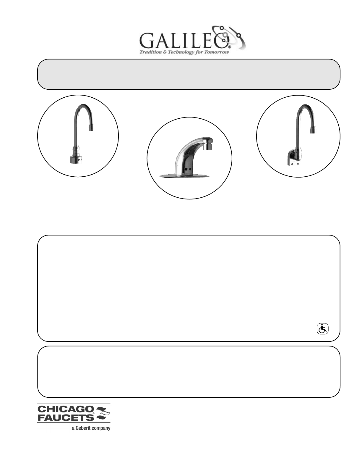
Gooseneck
Gooseneck
Faucet
Faucet
WWall Mount
all Mount
Faucet
Faucet
Lavatory
Lavatory
Faucet
Faucet
650/680 SERIES
650/680 SERIES
INST
INST
ALLA
ALLA
TION INSTRUCTIONS
TION INSTRUCTIONS
THE CHICAGO FAUCET COMPANY
2100 S. Clearwater Drive Des Plaines, IL 60018-5999
Phone: (847) 803-5000 Fax: (847) 803-5454
www.chicagofaucets.com
Trademarks
The Galileo 650/680 Series faucet spout design is licensed
under U.S. patent number D446,843 S and foreign counterparts.
U.S. patents pending on the Galileo 650/680 Series faucet
infrared electronics design. Synapse Commander and Synapse
Infrared are trademarks or registered trademarks of their
respective holders.
Copyrights
© 2003 Chicago Faucets Co. All rights reserved. The information in this manual is subject to change without notice.
Notice to Installers
Please leave this manual with the facility manager after completing the faucet installation. This document contains information
necessary for routine maintenance and servicing.
TABLE OF CONTENTS
Product Overview.....................................................................2
Available Faucet Options.........................................................2
Common Replacement Parts...................................................2
How to Order.............................................................................2
Care and Maintenance .............................................................2
Technical Support ....................................................................2
Safety Information ....................................................................3
Pre-Installation Setup...............................................................3
Model Identification..................................................................3
Component Identification ........................................................4
Las instrucciones en espanol comienzan en la pagina ................................................18
Les instructions en francais commencent a la page ....................................................36
Installation.................................................................................5
Gooseneck Faucet-Single Hole & Cover Plate..................5
Gooseneck Faucet-Wall Mount..........................................6
Lavatory Faucet .................................................................7
Solenoid and Optional Valves............................................8
Electronics Assembly (AC) ................................................9
Electronics Assembly (Battery Operated)........................10
Completed Installations....................................................11
Faucet Operation ....................................................................12
Changing Faucet Operation ..................................................12
Troubleshooting .....................................................................13
Warranty ..................................................................................16
ADA Compliant
Page 2
Printed in USA © 1004
Tag 680-4
2
650 / 680 SERIES
Installation & Maintenance Instructions
AVAILABLE FAUCET OPTIONS
4" and 8" (Centerset) Cover plate
(not available with wall mount versions)
Adjustable mechanical side-mix valve
– Catalog number 123-CP
Multi-unit hardwire transformer option for
Galileo 650/652/653 Series, handles up to eight units
– Catalog number 128-NF
Single unit plug-in transformer option for
Galileo 650/652/653 Series
– Catalog number 126-NF
CARE AND MAINTENANCE
All Chicago Faucets fittings are designed and engineered to
meet or exceed industry performance standards. Care
should be taken while cleaning this product.
• Use of abrasive cleaners, chemicals or solvents can
damage the faucet surface.
• Use mild soap with warm water for cleaning and protecting the life of the Chicago Faucets fittings. Make
sure the sensor eyes are kept clean and free of
obstructions.
• The solenoid assembly includes a strainer to catch particles in the water. Periodically clean the strainer to
keep it from clogging.
PRODUCT OVERVIEW
The Galileo 650/680 Series state-of-the-art motion sensing
faucet systems are designed to make life safer and easier.
The hands-free, touchless convenience produces a more
sanitary environment and promotes water conservation.
This user-friendly patented system adjusts automatically to
the environment. The craftsmanship and electronics design
make these faucets the best value in the market.
Mixing “Y”
– Catalog number 560-045KJKRBF
Thermostatic mixing valve (requires only a single supply
connection to the base fitting), handles up to 5 faucets
– Catalog number 119-NF
Stop Valve (supply-stop valves and check valves must be
used when hot and cold supplies are mixed ahead of the
solenoid valve) (with non-mixing valve models)
– Catalog number 441-LKC
For more information regarding faucet options, visit our website at www.chicagofaucets.com.
COMMON REPLACEMENT PARTS
Spout Assembly, Lavatory 570-001KJKCP
4" Cover Plate Assembly 570-003KJKCP
8" Cover Plate Assembly 570-008KJKCP
Sensor Collar Assembly 570-012KJKCP
Partition Assembly, DC 570-032KJKNF
Partition Assembly, AC 570-033KJKNF
Solenoid Wire Harness Assembly 570-039KJKNF
Electronics Box Assembly, DC 570-059KJKNF
Electronics Box Assembly, AC 570-060KJKNF
Gasket Kit 570-097KJKNF
Screw Kit 570-098KJKNF
Washer Kit 570-099KJKNF
4" Cover Plate Assembly
w/Side Mix Valve 570-071KJKCP
8" Cover Plate Assembly
w/Side Mix Valve 570-135KJKCP
Solenoid Assembly (Deck Mount) 570-144KJKRBF
Solenoid Assembly (Wall Mount) 570-145KJKRBF
Solenoid Rebuild Kit 570-344KJKNF
Wall Collar and Elbow Assembly 570-158KJKCP
HOW TO ORDER
Contact your local Chicago Faucets dealer or visit our website at www.chicagofaucets.com
- Close the supply lines and remove the filter nut.
- Wash or brush the strainer until clean.
- Do not overtighten the strainer when replacing.
• If water conditions are harsh, clean the solenoid and
outlet (spout).
TECHNICAL SUPPORT
For additional technical assistance, visit our website at
www.chicagofaucets.com, or call
1-800-TEC-TRUE (1-800-832-8783)
In addition, the Galileo 650/680 Series faucets support an
optional handheld maintenance tool called Geberit
Commander™. The patented Geberit Commander™ system uses wireless technology to communicate with the
faucet to provide troubleshooting and maintenance information along with faucet history and status, and for making
faucet adjustments.
For more information on the Geberit Commander™ system,
please contact your local Chicago Faucets dealer, or
www.chicagofaucets.com.
Page 3
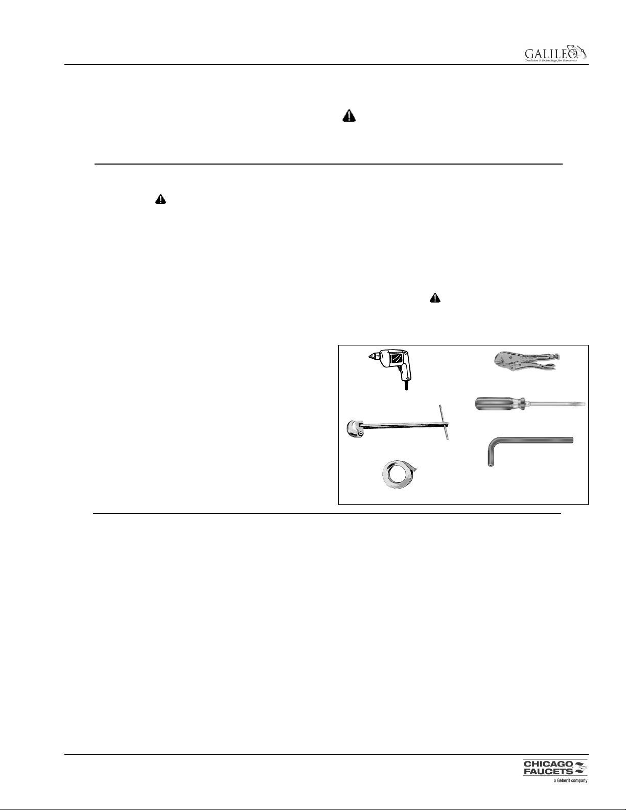
Required Tools and Supplies
Your Galileo faucet comes with all the components needed
for installation, however, tools and some supplies must be
furnished by you.
NOTE: Teflon tape is the recommended sealant.
CAUTION
Do not use pipe dope on faucet and supply
connections. Possible solenoid contamination could
occur and will void any warranty.
Printed in USA © 1004
Tag 680-4
3
650 / 680 SERIES
Installation & Maintenance Instructions
SAFETY INFORMATION
• Read this entire instruction sheet to ensure proper
installation.
• Compliance and conformity to local codes and ordinances is the responsibility of the installer.
• Flush all the water supply lines before making connections.
• File these instructions with the owner or maintenance department.
CAUTION indicates a practice or condition that
MAY result in damage to the equipment if the instruction or notice is ignored.
PRE-INSTALLATION SETUP
CAUTION
Make sure that water supply is completely off before
beginning installation.
Galileo 650 Series (AC) Faucets
The installation site should have access to an electrical box
with 120 volt AC, 60 Hz cycle for input to a transformer.
When installing the 126-NF transformer, the electrical box
should be within 6' of the sink. When installing the 128-NF
transformer, the electrical box should be within 50' of the
sink, if 18-gauge cable is used.
IMPORTANT: DO NOT attempt to operate multiple
faucets using a single-fitting transformer. Always use
128-NF transformer for multiple units.
Two types of transformer are available:
• Single fitting, plug-in
– Catalog number 126-NF
• Single fitting or multiple fittings (one to eight) hardwire
– Catalog number 128-NF
Galileo 680 Series Battery Powered (DC) Faucets
The faucets are powered by four “AA” alkaline batteries
(included).
Lavatory-style faucets are shipped with the spout, collar and
cover plate assembled.
Drill w/7/32" drill bit
Adjustable Locking Pliers
Basin Wrench
1/8" Hex Key (supplied)
Teflon Tape
Flat Blade Screwdriver
MODEL IDENTIFICATION
Gooseneck Faucet – Surface Mount
Model 652 Single Hole AC
Model 652-123 w/Side Valve AC
Model 652-4 w/4" Cover Plate AC
Model 652-4-123 w/4" Cover Plate & Side Valve AC
Model 652-8 w/8" Cover Plate AC
Model 652-8-123 w/8" Cover Plate & Side Valve AC
Model 682 Single Hole DC
Model 682-4 w/4" Cover Plate DC
Model 682-8 w/8" Cover Plate DC
Model 682-8-123 w/8" Cover Plate & Side Valve DC
Gooseneck Faucet – Wall Mount
Model 653 Single Hole AC
Model 683 Single Hole DC
Lavatory Faucet
Model 650 Single Hole AC
Model 650-4 w/4" Cover Plate AC
Model 650-8 w/8" Cover Plate AC
Model 650-8-123 w/8" Cover Plate & Side Valve AC
Model 680 Single Hole DC
Model 680-4 w/4" Cover Plate DC
Model 680-4-123CP w/4" Cover Plate & Side Valve DC
Model 680-8 w/8" Cover Plate DC
Model 680-8-123 w/8" Cover Plate & Side Valve DC
Side Mix Valve
(not available with wall mount)
Model 123-CP
Mixing Y-Valve
Model 560-045KJKRBF
Thermostatic Mixing Valve
Model 119-NF
Transformers
Model 126-NF, Plug-In
Model 128-NF, Hardwire
Replacing An Existing Faucet
Remove existing faucet, handles and supply lines from the
sink and supply stops.
Page 4
Printed in USA © 1004
Tag 680-4
4
650 / 680 SERIES
Installation & Maintenance Instructions
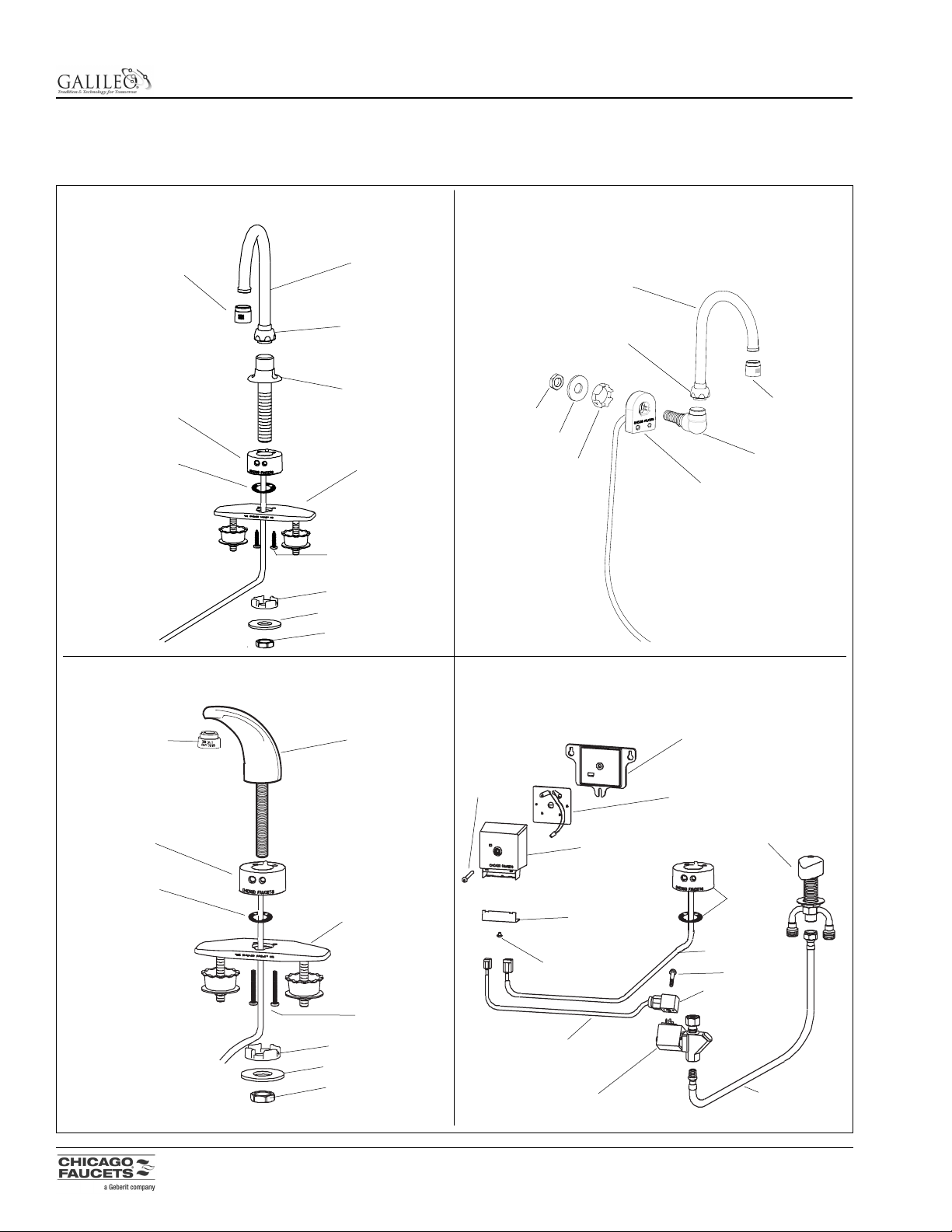
COMPONENT IDENTIFICATION
Care should be taken when unpacking shipping carton to avoid damage to unit and the following components enclosed. If any
parts are missing or damaged, contact your local Chicago Faucets dealer.
Gooseneck Faucet (shown w/cover plate) – Surface Mount
Lavatory Faucet (shown with cover plate) Electronic Box, Solenoid & Side Mix Valve
Gooseneck Faucet – Wall Mount
Spout
Spout
Spout Outlet
(Female)
Spout Outlet
(Female)
Spout Nut
Collar Elbow
Spout Nut
Spout Shank
Cover Plate
(4" or 8")
(if equipped)
Sensor Collar
Collar Gasket
Sensor Collar
Screw
Stilt Washer
Stilt Washer
Shank Washer
Shank Washer
Locking Nut
Locking Nut
Spout Outlet
(Male)
Stilt Washer
Shank Washer
Locking Nut
Sensor Collar
Collar Gasket
Spout
Cover Plate
(4" or 8")
(if equipped)
Screw
Baseplate
Partition Assembly
Electronics
Cover
123 Side Mix Valve
Screw
Screw
Screw
Collar &
Gasket
Outer Strain
Relief Bracket
Solenoid
DIN Connector
Stainless Steel
Flexible Hose
Cable
(Collar Assembly)
Cable
(Solenoid Assembly)
Page 5
Printed in USA © 1004
Tag 680-4
5
650 / 680 SERIES
Installation & Maintenance Instructions
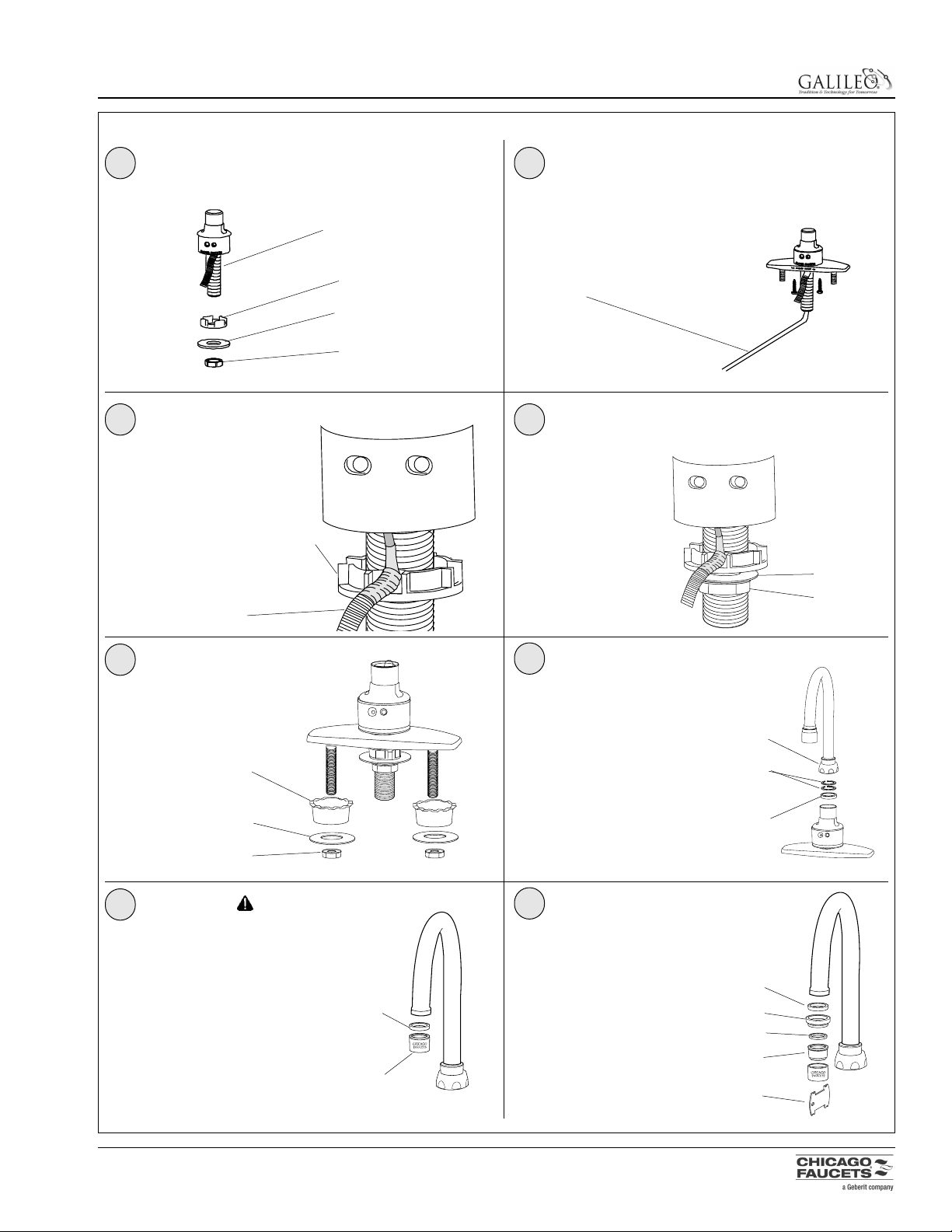
INSTALLATION – GOOSENECK FAUCET – SINGLE HOLE & COVER PLATE
1 2
3
4
7
5
6
8
Remove the locknut (1), washer (2), stilt washer (3) from
the spout shank (4). Remove shank from cover plate (if
supplied).
Install stilt washer (1) all
the way up onto shank,
crown side up. Position
sensor cable (2) through
one of the rounded slots
in the stilt washer (1).
If faucet was installed with
cover plate, secure cover
plate with basin washers (1),
flat washers (2) and locknuts
(3).
Install the shank washer (1) and locknut (2) onto faucet
shank. Tighten locknut securely to prevent collar and spout
from rotating. If necessary, support spout base from above
to prevent twisting.
Install spout nut (1) onto the
spout.
For swivel mount, only install
two plastic split washers (2).
For rigid mount, only install
1/8" thick plastic washer (3).
Mount the spout completely
into the base and securely
tighten the spout nut (1).
Attach the outlet assembly (1) and
aerator gasket (2) to the spout.
The outlet assembly is equipped
from the factory with a 0.5 GPM
cartridge (white screen). To configure the outlet with the 2.2 GPM
cartridge (yellow screen) see step
8.
If 0.5 GPM spout is to be used,
skip step 8 and proceed to
Installation - Solenoid and
Optional Valves, page 8.
To convert outlet assembly to
2.2 GPM:
1. Disassemble outlet assembly using key (1).
2. Remove the 0.5 GPM cartridge (white screen) and
replace it with the 2.2 GPM
cartridge (2).
3. Install the rubber washer
(3), adapter (4) and aerator
gasket (5).
Proceed to Installation Solenoid and Optional
Valves, page 8.
Install faucet assembly into deck hole.
Use plumbers putty to seal faucet to deck.
4
3
2
3
1
1
1
2
3
4
5
2
2
2
2
1
3
1
1
1
2
Be careful not to
nick or cut the sensor cable during
installation.
)
)
CAUTION
Flush water lines before performing this step.
Page 6
Printed in USA © 1004
Tag 680-4
6
650 / 680 SERIES
Installation & Maintenance Instructions
INSTALLATION – GOOSENECK FAUCET – WALL MOUNT
1 2
3
Remove the locknut (1), washer (2), stilt washer (3) from
the shank (4).
Install the shank washer (1) and locknut (2) onto faucet
shank. Tighten locknut securely to prevent spout
from rotating. Install elbow (3) using Teflon tape on threads.
NOTE: Make sure collar is not resting on cable while tightening. Support wall collar assembly while tightening elbow.
Install the sensor collar
assembly into the wall hole.
Install stilt washer (1) all the
way up onto shank, crown
side in. Position sensor
cable (2) through one of the
rounded slots in the stilt
washer
4
3
2
1
1
2
Be careful not to nick or cut the sensor cable during installation.
3
2
1
5
1
2
6
4
Install spout nut (1) onto the
spout.
For swivel mount, only install
two plastic split washers (2).
For rigid mount, only install
1/8" thick plastic washer (3).
Mount the spout completely
into the base and securely
tighten the spout nut (1).
1
1
3
4
5
2
3
2
Attach the outlet assembly (1) and
aerator gasket (2) to the spout. The
outlet assembly is equipped from the
factory with a 0.5 GPM cartridge
(white screen). To configure the outlet
with the 2.2 GPM cartridge (yellow
screen) see step 6.
To convert outlet assembly to 2.2
GPM:
1. Disassemble outlet assembly
using key (1).
2. Remove the 0.5 GPM cartridge
(white screen) and replace it
with the 2.2 GPM cartridge (2).
3. Install the rubber washer (3),
adapter (4) and aerator gasket
(5).
If 0.5 GPM is to be used, proceed to Installation Solenoid and Optional Valves, page 8.
)
Proceed to Installation - Solenoid and Optional
Valves, page 8.
)
CAUTION
Flush water lines before performing this step.
Page 7

Printed in USA © 1004
Tag 680-4
7
650 / 680 SERIES
Installation & Maintenance Instructions
INSTALLATION – LAVATORY FAUCET
1 2
5
7
6
Remove the locknut (1), washer (2), stilt washer (3) from
the spout shank (4).
If faucet was installed with cover plate, secure cover plate
with basin washers (1), flat washers (2) and locknuts (3).
Install the faucet assembly into the deck hole.
Use plumbers putty to seal faucet to deck.
4
3
2
1
Be careful not to nick or cut the
sensor cable during installation.
1
1
2
3
4
5
1
2
2
3
To convert outlet assembly to 2.2 GPM:
1. Disassemble outlet assembly using key (1).
2. Remove the 0.5 GPM cartridge (white screen) and
replace it with the 2.2 GPM cartridge (2).
3. Install the rubber washer (3), adapter (4) and aerator
gasket (5).
4
Install the shank washer (1) and locknut (2) onto faucet
shank. Tighten locknut securely to prevent spout
from rotating. If necessary, support spout base from above
to prevent twisting.
2
1
Attach the outlet assembly (1)
and aerator gasket (2) to the
spout. The outlet assembly is
equipped from the factory with a
0.5 GPM cartridge (white
screen). To configure the outlet
with the 2.2 GPM cartridge (yellow screen) see step 7.
If 0.5 GPM is to be used, proceed to Installation Solenoid and Optional Valves, page 8.
)
)
Proceed to Installation - Solenoid and Optional Valves,
page 8.
3
Install stilt washer (1) all
the way up onto shank,
crown side up. Position
sensor cable (2) through
one of the rounded slots
in the stilt washer (1).
2
1
CAUTION
Flush water lines before performing this step.
Page 8

Printed in USA © 1004
Tag 680-4
8
650 / 680 SERIES
Installation & Maintenance Instructions
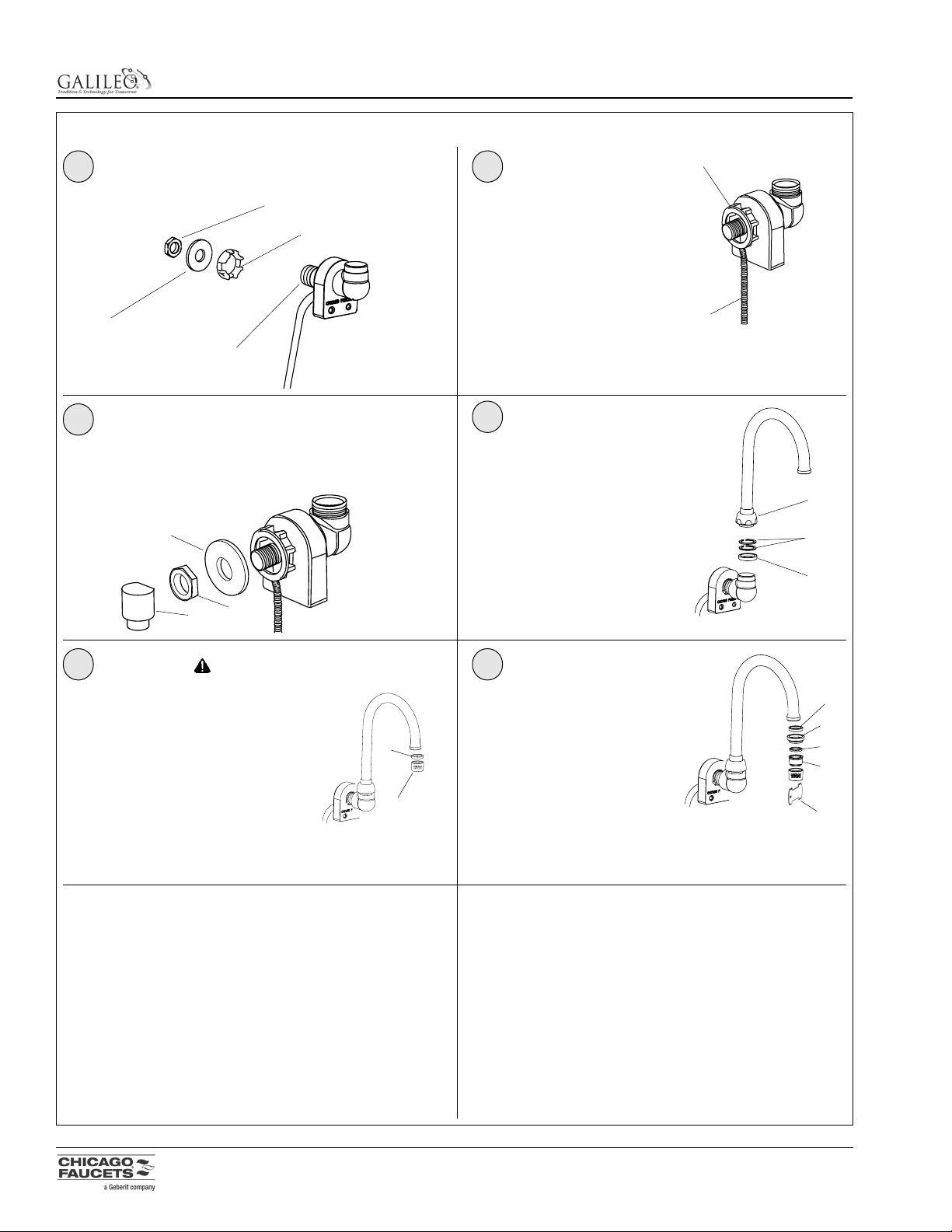
INSTALLATION – SOLENOID AND OPTIONAL VALVES
1 2
3
5
7
4
6
8
Attach the supply lines to side valve.
Connect the intermediate supply line (1) to the bottom
outlet of the side valve and to the solenoid assembly inlet.
Use Teflon tape on the threads to ensure a leak-free joint.
If required, install any optional equipment and connect to
the solenoid. The valves listed here require only a single
supply connection to the base fitting on the solenoid.
• Side mix valve (steps 3, 4, 5 & 6)
- Catalog number 123-CP
• Mixing “Y” valve (step 7)
Catalog number 560-045KJKRBF
• Thermostatic mixing valve (not shown)
- Catalog number 119-NF
If used, assemble the “Y” valve (1) to the nipple (2) supplied,
then connect the “Y” valve to the the solenoid assembly inlet.
Use Teflon tape on all threads to ensure a leak-free joint.
Proceed to Installation - Electronic Box
(AC or Battery Operated, depending on model),
page 9 or 10.
If equipped with a side valve, assemble the nut (1) and flat
washer (2) to the valve shank. Install the side valve assembly up into the mounting plate and secure from the top with
the chrome c-clip (3) provided.
Assemble the chrome valve handle (1) to the side valve
using the screw (2) and cap (3) provided.
Thread the union nut (1) of the solenoid assembly to the
faucet shank (2). Use Teflon tape on the threads to
ensure a leak-free joint. Make sure the solenoid is positioned for easy access. Tighten the union nut.
1
1
1
2
2
3
2
3
CAUTION
Do not use pipe dope on
threads. The solenoid
could become contaminated and will void any
warranty.
CAUTION
Do not use pipe
dope on threads.
The solenoid could
become contaminated and will void any
warranty.
CAUTION
Do not use pipe dope
on threads. The solenoid could become
contaminated and will
void any warranty.
1
1
2
NOTE: For single-hole
application substitute
threaded deck flange
for C-clip.
HOT
(red dot)
)
Page 9

Printed in USA © 1004
Tag 680-4
9
650 / 680 SERIES
Installation & Maintenance Instructions
INSTALLATION – ELECTRONIC BOX (AC)
650 / 680 MODEL
ELECTRONICS BOX MOUNTING TEMPLATE
INSTRUCTIONS
1. REMOVE BACKING AND PLACE THIS TEMPLATE WHERE ELECTRONICS
BOX IS TO BE MOUNTED.
2. DRILL 3 PILOT HOLES AT THE LOCATIONS INDICATED ON THIS TEMPLATE.
3. PARTIALLY FASTEN 3#10 WOOD SCREWS (USE ANCHORS IF NECESSARY)
INTO MOUNTING SURFACE.
4. SEPARATE ELECTRONICS COVER FROM BASEPLATE BY LOOSENING
1/8" HEX ALLEN SCREW.
5. ATTACH BASEPLATE TO WALL AND COMPLETE TIGHTENING
SCREWS INTO WALL.
1
3
4
6
7
5
2
8
Install baseplate and mount the electronic box to the wall
location chosen in step 1. Make sure transformer wires (1)
are positioned in the baseplate channel (2) before mounting unit.
CAUTION
DO NOT turn on water supply until all electrical
connections are made.
CAUTION
Faucet will automatically calibrate when sensor cable is connected and power is supplied. DO NOT place objects in front
of collar sensor for first 30 seconds after power-up.
Follow the directions on the electronic box mounting template
supplied. Affix the template to the wall, either level with or
above solenoid valve, and within 12" of the solenoid valve.
When installing the 126-NF transformer, the electrical box
should be within 6' of the sink. When installing the 128-NF
transformer, the electrical box should be within 50' of the sink,
if 18-gauge cable is used.
Install solenoid cable plug (1) into the smaller, telephonestyle jack in the electronic box. Install faucet sensor cable
plug (2) into the larger RJ-45 jack.
Attach strain relief cover (1) with screw (2) using hex key
provided (3).
Feed the wires from the transformer through the baseplate.
Connect the 1/4" spade terminal to the positive (+) terminal
and connect the 3/16" spade terminal to the negative (-)
terminal. Terminals are two different sizes and match
corresponding terminal clips from transformer. Clips are not
provided with the 128-NF transformer.
NOTE: To ensure the
electronic box is level
with or above the solenoid valve, the cables
should create a drip
loop. The electronic box
is designed with the
wire connectors facing
downward to ensure
proper drip loops.
Plug the transformer into the applicable electrical receptacle.
Wait at least 30 seconds, then turn on the water supply.
NOTE: When power is initially supplied, the LED on the electronic
box will blink and an audible indicator chirps twice per second
whenever hand presence is detected. This will continue for 8
minutes and then stop.
Remove the strain relief
cover and screw (1)
using hex key provided
(2).
NOTE: The faucet will automatically calibrate when
sensor cable is connected
and power is supplied. See
step 8.
NOTE: For inwall or multi-unit
installations refer
to instructions
included with the
transformer.
1
2
2
1
1
1
3
2
1
2
2
CAUTION
Do not attempt to operate multiple faucets using a 126-NF
single transformer.
Proceed to FAUCET OPERATION, page 12.
)
Re-attach the electronic box to the baseplate location
using screw(1) and hex key provided (2).
NOTE: When positioning baseplate, make
sure there is enough
room for drip loops in
final installation. See
Note in step 7.
Page 10

Printed in USA © 1004
Tag 680-4
10
650 / 680 SERIES
Installation & Maintenance Instructions
INSTALLATION – ELECTRONIC BOX (BATTERY OPERATED)
650 / 680 MODEL
ELECTRONICS BOX MOUNTING TEMPLATE
INSTRUCTIONS
1. REMOVE BACKING AND PLACE THIS TEMPLATE WHERE ELECTRONICS
BOX IS TO BE MOUNTED.
2. DRILL 3 PILOT HOLES AT THE LOCATIONS INDICATED ON THIS TEMPLATE.
3. PARTIALLY FASTEN 3#10 WOOD SCREWS (USE ANCHORS IF NECESSARY)
INTO MOUNTING SURFACE.
4. SEPARATE ELECTRONICS COVER FROM BASEPLATE BY LOOSENING
1/8" HEX ALLEN SCREW.
5. ATTACH BASEPLATE TO WALL AND COMPLETE TIGHTENING
SCREWS INTO WALL.
1
3
4
7
5
6
8
Mount the electronic box to the wall location using
screw(1) and hex key provided (2).
CAUTION
DO NOT turn on water supply until all electrical
connections are made.
Install solenoid cable plug (1) into the smaller, telephonestyle jack in the transformer. Install faucet sensor cable
plug (2) into the larger RJ-45 jack.
Attach strain relief cover (1) and screw (2) using hex key
provided (3).
Install 4 “AA” alkaline batteries into battery holder. Observe
battery polarity.
Turn on the water supply.
Remove the strain relief cover and screw (1) using hex
key provided (2).
NOTE: When power is initially supplied, the LED on the electronic box will blink and an audible indicator chirps twice per second
whenever hand presence is detected. This will continue for 8
minutes and then stop.
Follow the directions on the electronic box mounting template supplied. Affix the template to the wall, either level with
or above solenoid valve, and within 12" of the solenoid
valve.
NOTE: To ensure the
electronic box is level
with or above the solenoid valve, the cables
should create a drip loop
The electronic box is
designed with the wire
connectors facing downward to ensure proper
drip loops.
1
2
1
2
1
2
3
1
2
3
Proceed to FAUCET OPERATION, page 12.
)
CAUTION
Faucet will automatically calibrate when sensor cable is connected. DO NOT place objects in front of collar sensor for
first 30 seconds after power-up.
NOTE: When positioning
baseplate, make sure
there is enough room for
drip loops in final installation. See Note in step 6.
2
Install baseplate and mount the electronic box to the wall
location chosen in step 1.
With baseplate
NOTE: When positioning baseplate, make
sure there is enough
room for drip loops in
final installation. See
Note in step 6.
1.5V
or UM-3X2
SIZE "AA" or EQUIV.
COMF
1.5V
or UM-3X2
SIZE "AA" or EQUIV.
COMF
Page 11

Printed in USA © 1004
Tag 680-4
11
650 / 680 SERIES
Installation & Maintenance Instructions
COMPLETED INSTALLATIONS
Gooseneck Faucet – Surface Mount
(shown with cover plate)
Gooseneck Faucet – Surface Mount
(shown with cover plate & side valve)
Gooseneck Faucet – Wall Mount
Lavatory Faucet
(shown with cover plate & side valve)
Lavatory Faucet
(shown with cover plate )
Page 12

CHANGING FAUCET OPERATION
In order to change any faucet option, the DIPswitch must be
used (located inside the electronics cover assembly, see
illustration this page).
Checking/Changing DIPswitch Settings
1. Remove the electronics cover (1) from the baseplate
(2).
2. Lift the partition (3) out to expose the circuit board and
DIPswitch.
3. To change a DIPswitch setting, use a small pointed
object to move the appropriate DIPswitch to ON or
OFF.
Faucet range and mode settings along with their
corresponding DIPswitch settings are outlined in Table 1 and
Table 2
Resetting Faucet Electronics
In order to reset the faucet electronics, a reset button located inside the electronics cover assembly must be pushed in
(see illustration this page).
To reset faucet electronics:
1. Remove hex screw holding the electronics cover to
the baseplate and remove cover.
2. Lift the partition out to expose the circuit board and
reset button.
3. Make sure there are no objects in front of the collar
sensor, then push the button to reset.
4. Wait 30 seconds for faucet to automatically calibrate
to the environment.
5. Activate water flow by placing your hand in front of the
sensor.
6. Place partition into the electronics cover.
7. Place the electronics cover onto the baseplate and
secure with the hex screw.
Printed in USA © 1004
Tag 680-4
12
650 / 680 SERIES
Installation & Maintenance Instructions
ON
ON
OFF
OFF
1 2 3 4 5
1 2 3 4 5
MANUAL
RESET
BUTTON
DIPSWITCHES
Electronics Cover Assembly & DIPswitch
Range Short Normal Far Maximum
Switch 1 off on on off
Switch 2 off off on on
Table 1 - Faucet Range
Normal Scrub Meter Water Saver
Modes Mode Mode Mode Mode
Switch 3 off on off off
Switch 4 off off on off
Switch 5 off off off on
Table 2 - Faucet Mode
FAUCET OPERATION
Range Modes
• Normal - Gooseneck or Lavatory spout, 4-3/4" spout
(factory default)
• Short - Gooseneck, 3-1/2" spout
• Far - Long Gooseneck, 5-3/8" spout
• Maximum - Long Gooseneck, 8" spout
Operating Modes
• Normal Motion Detecting Mode: water flows within 1/4
second after activating sensor (i.e., putting hands in
front of collar) and continues to stay on as long as
motion is detected. Maximum time is 45 seconds
(factory default setting).
• Scrub Mode: water continues to flow for 60 seconds
(default) after deactivating the sensor (removing
hands).
• Metered Mode: water flows for 10 seconds (default)
from first hand detection.
• Water Saver Mode: water flows for a maximum of 5
seconds starting from first hand detection and immediately turns off when hands are removed.
Additional Operating Features
• 12 second, no-motion turn off in normal mode
• Low-battery indication
• Battery life up to one year depending on use
frequency.
3
1
2
Page 13

NOTE: Resetting the faucet electronics causes loss of virtual settings and time in use, and will also start the 8 minute
timer where the LED on the electronics box will blink and an
audible indicator chirps twice per second whenever hand
presence is detected. The optional Geberit Commander™
hand held maintenance tool can also be used to reset all
faucet electronics.
Printed in USA © 1004
Tag 680-4
13
650 / 680 SERIES
Installation & Maintenance Instructions
The optional Geberit Commander™ handheld maintenance
tool makes changing faucet operation settings easy, and
provides access to additional faucet options such as delay
times - all without opening the electronics cover assembly.
For more information, please contact your Chicago Faucets
dealer or visit www.chicagofaucets.com.
TROUBLESHOOTING
Whenever new batteries are installed, AC power is applied,
or a manual reset button is pressed, the LED on the electronics cover will blink and an audible indicator chirps twice
per second whenever hand presence is detected. After 8
minutes, the LED and buzzer function stops.
If an error occurs, the LED will blink and the buzzer will
sound every 30 seconds to assist in diagnosing the problem. When corrective action is taken the LED and buzzer
will stop.
The following chart provides details concerning the number
of beeps and possible errors associated with them .
1 Beep: Indicates low battery.
2 Beeps: Calibration out of range (environment too reflec-
tive).
3 Beeps: Room infrared level out of range; too much sun-
light, heat lamp present, etc.
4 Beeps: Solenoid short circuit.
5 Beeps: Solenoid unplugged or loose/broken solenoid
connection.
See Troubleshooting Chart on pages 14 & 15 for further
troubleshooting information.
Page 14

Printed in USA © 1004
Tag 680-4
14
650 / 680 SERIES
Installation & Maintenance Instructions
Disassemble solenoid and inspect/clean parts.
Reduce pressure to under 80 PSI.
Attach side mix valve outlet to solenoid valve using
flexible hose (page 8).
Change range setting using DIPswitch (page 12)
or Commander™ software.
Turn on water supply.
Check connection.
Replace electronics cover.
Check connection.
Inspect collar wiring for signs of damage or corrosion. Replace if necessary.
Replace cover assembly.
Reduce pressure to under 80 PSI.
Replace batteries (DC only).
Use correctly sized terminal clips (page 9).
Faucets must be wired in parallel from transformer
(transformer to each individual unit), not connected
in a series.
If polarity was reversed, replace partition (part no.
570-033KJKNF).
After 60 seconds, or another Palm
Communication, the faucet will return to operating
mode.
Remove interference; reset electronics using reset
button (page 12) or Commander™ software. Allow
30 seconds for faucet to automatically re-calibrate.
Change range setting using DIPswitch (page 12)
or Commander™ software.
Change range setting using DIPswitch (page 12)
or Commander™ software.
Water runs continuously.
Faucet turns on by itself
(ghosting).
No water flow.
Debris in solenoid (no beeps).
Water pressure too high (no beeps).
Side mix valve installation (no beeps).
Incorrect range setting for spout type and
sink used (2 beeps).
Water not turned on (no beeps).
Solenoid cable not connected to electronics cover (5 beeps).
Solenoid short circuit (4 beeps).
Sensor cable not connected to electronics
cover (no beeps).
Inoperative sensor (no beeps).
Inoperative electronics cover assembly
(no beeps).
Water pressure too high (no beeps).
Low battery voltage (DC only) (1 beep).
6VDC transformer not properly connected
to partition assembly (no beeps).
Wiring of multiple unit 6VDC transformer
(no beeps).
Check wiring polarity.
While communicating with faucet, the
Palm device was pulled away before communications ended (no beeps).
Interference during automatic calibration
(no beeps).
Incorrect range setting for type of spout
and sink used.
Lighting environment affecting sensor
(3 beeps).
Problem Check Possible Solution
Troubleshooting Chart
Range too short or too long.
Page 15

Printed in USA © 1004
Tag 680-4
15
650 / 680 SERIES
Installation & Maintenance Instructions
Replace solenoid.
Change mode or range setting using DIPswitch
(page 12) or Commander™ software.
Clean internal parts or replace solenoid valve.
Clean outlet.
Change mode setting using DIPswitch (page 12)
or Commander™ software.
Electronics cover must be mounted to allow for
drip loops for the sensor and solenoid cables
(pages 9 & 10).
Clean connector.
Reset electronics using reset button (page 12) or
Commander™ software.
Clogged strainer. Clean if necessary.
Clean faucet outlet.
Replace batteries if below 4.2 volts.
Change range setting using DIPswitch (page 12)
or Commander™ software.
Replace sensor.
Faucet works in reverse.
Faucet turns off too soon.
Faucet stays on longer than
normal.
Faucet stopped working.
No Commander™ Palm communications.
Solenoid wiring on DIN connector
(no beeps).
Faucet operating mode (no beeps) or
faucet range setting.
Dirty solenoid valve (no beeps).
Clogged spout outlet.
Faucet in wrong mode (no beeps).
Mounting of electronics cover (no beeps).
Sensor cable connector.
No clicking sound from solenoid during
hand presence (no beeps).
Solenoid valve strainer.
Check if faucet outlet is clogged
(no beeps).
Battery voltage (battery operated only).
Incorrect range setting for spout type and
sink used (no beeps).
Inoperative sensor (no beeps).
Problem Check Possible Solution
Page 16

Printed in USA © 1004
Tag 680-4
16
650 / 680 SERIES
Installation & Maintenance Instructions
WARRANTY
PRICES - Prices quoted herein are subject to change without notice and all orders are accepted subject to prices prevailing at time of order
entry.
TERMS OF PAYMENT - Terms are 2% 45 days 60 net. Cash discounts must be calculated on the total amount of the invoice, before transportation charges and any applicable taxes. A 1-1/2% per month service charge will be added to all past due invoices. Annual rate of 18%.
TAX NOTICE - Any manufacturers' or sales tax applicable thereto will be added to the prices and terms herein contained.
CREDIT APPROVAL - All orders are subject to credit approval by the CHICAGO FAUCET COMPANY'S Credit Department prior to acceptance
of the order. Orders may be refused, delivery may be withheld or shipments stopped in transit on accepted orders without any liability on the
Company's part, if, in its sole opinion, the buyer's ability to pay for the merchandise on the terms and conditions contained herein is in doubt.
All New Accounts must submit a $500.00 net minimum order with credit and bank references.
SHIPPING AND HANDLING - All sales are F.O.B., shipping point. The Company will allow full freight at the prevailing CWT rate on shipments
of Company's products with a net invoice value of $1,500.00 or 24 pieces, * when shipments are within the continental United States and have
as destination the buyer's usual business address or designated job location. Freight allowed on shipments to Alaska shall be calculated
F.A.S., Seattle, Washington. The use of the term "F.A.S., Seattle, Washington" in this paragraph shall not be deemed to impose any risk or
obligation concerning the goods or the shipment thereof upon the Company after the delivery of the goods to the initial carrier. Under no circumstances will a direct C.O.D. shipment be made to the wholesaler's customer.
* Original P.O. must meet FFA terms. Subsequent additions will not be considered towards freight allowance.
Routing of shipments shall be determined at the sole discretion of the Company.
DELIVERY - Delivery to the initial carrier shall constitute delivery to the buyer. CHICAGO FAUCET COMPANY'S responsibility, insofar as
transportation risks are concerned, ceases upon delivery in good order to such carrier, and all goods are shipped at the buyer's risk. The buyer
is requested to check each incoming shipment carefully before acknowledging receipt from the carrier. If goods are visibly damaged the buyer
should insist that written confirmation of the damage be noted on the freight bill by the carrier. If concealed damage is noted after unpacking,
the buyer should immediately notify the carrier involved and obtain verification of the damage from the carrier.
Claims for shortages in orders will not be considered unless presented to the Company within 30 days after receipt of goods by the buyer.
DAMAGE - All claims for damage in transit, shortage, or nondelivery must be filed against the carrier by the buyer.
CHICAGO FAUCET COMPANY will not be responsible for delay in shipment of goods, or for any damages suffered by reasons thereof, when
such delay is occasioned by accident, fire, flood, embargo, strike, war, labor stoppages, inadequate transportation, shortage of materials, delay
or default on the part of vendors, government regulations or any other cause beyond its control.
CHICAGO FAUCETS BRAND PRODUCTS ARE SUBJECT TO THE FOLLOWING WARRANTIES:
LIMITED WARRANTY - The CHICAGO FAUCET COMPANY ("Chicago Faucets") extends to the original consumer the following warranties for
Genuine Chicago Faucets manufactured products and components, or other components under the Chicago Faucets Warranties, (collectively,
the "Products") used in commercial or residential applications.
LIFETIME FAUCET WARRANTY - The "Faucet", defined as any metal cast, forged, stamped or formed portion of the Product, not including
electronic or moving parts or water restricting components, or other components covered under other Chicago Faucet warranties, is warranted
against manufacturing defects for the life of the Product.
FIVE YEAR CARTRIDGE WARRANTY - COMMERCIAL _ The "Cartridge", defined as the metal portion of any Product typically referred to by
the product numbers containing 1-099, 1-100, 1-310, 377X, 217X and 274X, excluding any rubber or plastic components, is warranted against
manufacturing defects for a period of five (5) years from the date of Product purchase. All Cartridges included in Chicago Faucet's Single
Control or Shower Products are also warranted against manufacturing defects for a period of five (5) years from the date of Product purchase.
LIFETIME CARTRIDGE WARRANTY - RESIDENTIAL - For products used in Residential applications, the "Cartridge", as described above, is
warranted for the lifetime of the faucet.
ONE-YEAR FINISH WARRANTY - COMMERCIAL - For Products used in commercial applications, the finish of the Product is warranted
against manufacturing defects for a period of one-year from the date of Product purchase. PVD finishes installed in public or commercial areas
carry a one-year warranty from date of installation.
ONE-YEAR FINISH WARRANTY - RESIDENTIAL - PVD finishes installed in public or commercial areas carry a one-year warranty from date
of installation.
Page 17

Printed in USA © 1004
Tag 680-4
17
650 / 680 SERIES
Installation & Maintenance Instructions
FIVE-YEAR FINISH WARRANTY - RESIDENTIAL - For Products used in residential applications, the finish of the Product is warranted against
manufacturing defects for a period of five (5) years from the date of Product purchase. ForeverShine™ finishes installed in residential-use
applications are warranted not to corrode, tarnish or discolor for the life of the product.
ELECTRONIC FAUCETS MECHANICALS WARRANTY - Are warranted for 5 years from the date of installation.
ELECTRONIC FAUCETS FINISHES WARRANTY - Are warranted for one-year from the date of installation.
ELECTRONIC FAUCETS ELECTRONICS AND SOLENOID WARRANTY - Are warranted for one-year from the date of installation.
OTHER WARRANTIES - All other Products not covered above are warranted against manufacturing defects for a period of one (1) year from
the date of Product purchase.
GEBERIT BRAND PRODUCTS ARE SUBJECT TO THE FOLLOWING WARRANTIES:
KITCHEN ACCESSORIES shall be free from defective material and workmanship for a period of 1-year from date of installation.
BATH WASTE and OVERFLOW products carry a limited lifetime warranty on the material and mechanism
Tessera™ concealed tank & carrier units carry a 10-year limited warranty on the flushing mechanisms and limited lifetime warranty on the tank
and carrier.
PLATED FINISHES carry a one-year limited warranty from date of installation with the exception of those finishes designated as
ForeverShine™.
ForeverShine™ finishes installed in residential-use applications are warranted not to corrode, tarnish or discolor for the life of the product.
ForeverShine™ finishes installed in commercial use applications are warranted for a period of one-year from date of installation.
ELECTRONIC FAUCETS, FLUSHOMETERS AND METERING MECHANICALS WARRANTY - Are warranted for 5 years from the date of
installation.
ELECTRONIC FAUCETS FINISHES WARRANTY - Are warranted for one-year from the date of installation.
ELECTRONIC FAUCETS ELECTRONICS AND SOLENOID WARRANTY - Are warranted for 3 years from the date of installation.
PRESSURE ASSIST TOILET SYSTEMS - Are warranted for 5 years from date of installation (pressure vessel), limited lifetime for the carrier
plus a one-year warranty on toilet bowl and flush actuator plate.
Chicago Faucets will either replace or repair the defective equipment or refund the purchase price, at its option, if an inspection by Chicago
Faucets or its authorized representative discloses any manufacturing defects in material or workmanship during this period. These provisions
do not include the battery shipped with the Electronic Products. Chicago Faucets will not be liable for any labor or other expenses not specifically stated above and disclaim any responsibility for incidental or consequential damages.
Warranties implied by law, including that of merchantability are expressly limited to the period of this warranty. This limitation and exclusion
does not apply in those states that do not allow limitations on the duration of implied warranties. Or the exclusion may not apply to you. This
warranty gives you specific legal rights and you may have other rights, which vary, from state to state.
RETURNED GOODS - Merchandise may not be returned to the Company for credit unless the buyer obtains prior written approval from the
Company. Such approval will be granted only when material to be returned is a Standard or MTO product and is listed in the current price
sheets. Credit will be issued on all material returned by permission, at the prevailing price at time of purchase, less a handling charge of up to
35%. No credit whatever will be allowed on products designated as Custom (Custom products are products not designated as Standard or
MTO) which have been shipped according to customers' specification. Material, which is marred or damaged, will not be accepted. All transportation costs for returned goods must be paid by the buyer.
ORDER MODIFICATION/CANCELLATION - Orders for Standard and MTO products can be modified or cancelled up to the time the order is
being processed for shipment. A Chicago Faucets customer service representative must confirm the status of order to be cancelled or changed
in order to avoid any restocking fees or charges. Changes to the order can potentially extend the acknowledged availability date. Once
entered, Custom products are non-cancelable, and will be shipped and billed to the customer.
The Company reserves the right to make reasonable changes of any kind in its products and their packaging without notice.
MINIMUM CHARGE - No invoice will be made for less than $100.00 (One Hundred Dollars Net) on faucets, valves and fittings or repair parts.
NOTE: Possession of this price sheet by any person is not to be construed as an offer to sell him or anyone else, the goods listed herein at
prices stated.
 Loading...