

Page 1
Page 2

This machine has been engineered to our own rigid safety and performance standards. It has
been designed to comply with sanitation and health guidelines recommended by the
Automatic Merchandising Health-Industry Council (AMHIC) and it conforms with all other
NAMA safety recommendations.
This machine has been manufactured in accordance with the safety standards of both
Underwriter’s Laboratories and the Canadian Standards Association. To maintain this
degree of safety and to continue to achieve the level of performance built into this machine,
it is important that installation and maintenance be performed so as to not alter the original
construction or wiring and that replacement parts are as specified in the Parts and Service
Manual. Your investment in this equipment will be protected by using this Operator’s Guide
and the Parts and Service Manual in your operation, service and maintenance work. By
following prescribed procedures, machine performance and safety will be preserved.
Page 3

EURODRINK OPERATOR'S GUIDE
TABLE OF CONTENTS
Specifications ............................................................................................................... iv
Major Parts ................................................................................................................... vi
Controls and Indicators ................................................................................................ x
I. LOCATION PREPARATION..................................................................................... 1
Electrical Power Requirements ............................................................................. 1
Water Requirements .............................................................................................. 2
II. POSITIONING THE MERCHANDISER................................................................... 3
III. CONNECTING EVERYTHING................................................................................ 3
Connect the Merchandiser to the Water Supply................................................... 3
Connect the Merchandiser to the Electrical Power Supply .................................. 3
IV . FINAL MECHANICAL PREPARATION .................................................................4
1. Level the Merchandiser .................................................................................... 4
2. Mount the Base Plate........................................................................................ 5
3. Install the Water Filter Cartridge ....................................................................... 6
4. Load the Optional Filter Paper.......................................................................... 9
5. Install the Optional Coin Box Lock ................................................................. 11
6. Set Up and Load the Coin Mechanism .......................................................... 12
7. Fill the Tank...................................................................................................... 14
8. Fill the Canisters.............................................................................................. 14
9. Load Cups ....................................................................................................... 15
10. Tell the Machine About the Cup Sizes ......................................................... 15
11. Test the Machine ........................................................................................... 17
V. ADJUSTMENTS AND MINOR MAINTENANCE .................................................. 18
1. Empty the Bill Stacker ..................................................................................... 18
2. Adjust the Water Valves .................................................................................. 18
3. Adjust the Air Pressure.................................................................................... 19
4. Install Canisters............................................................................................... 19
5. Adjust the Cup Mechanism............................................................................. 20
6. Set Up the Menu Assembly ............................................................................ 21
TABLE OF CONTENTS
PROGRAMMING THE EURODRINK......................................................................... 23
Getting around ............................................................................................................ 2 3
The Service Keypad............................................................................................. 23
The Selection Switch Panel ................................................................................. 23
The Displays ......................................................................................................... 2 5
The Function Keys ............................................................................................... 26
Other Keys............................................................................................................ 26
Control Panel Switch Functions Explained................................................................ 27
Programming Flowcharts ............................................................................................ 28
Programming Procedures .......................................................................................... 36
The Supervisor Mode........................................................................................... 36
Gain Access to the Supervisor Mode ............................................................... 37
Enter a New Supervisor Code .......................................................................... 37
Enter a Freevend Code .................................................................................... 37
Lock or Unlock Mode or Payout Keys.............................................................. 38
Set Printer or Dex Options................................................................................ 38
Lock or Unlock Data Clearing Access .............................................................. 39
Select Display Language ..................................................................................... 39
Select Coin Mechanism and Options .................................................................. 40
Select Bill Validator and Options.......................................................................... 40
6360052 Page - i July, 2001
Page 4

EURODRINK OPERATOR'S GUIDE
Select Monetary Options...................................................................................... 42
Set declining balance ........................................................................................ 42
Set currency acceptance on low change .......................................................... 43
Set overbuy options........................................................................................... 43
Set last bill stacking options .............................................................................. 43
Select Card Reader Options................................................................................ 44
Set Up Winner Mode ............................................................................................ 45
Set Up the Mug Discount ..................................................................................... 46
Set the Printer Baud Rate .................................................................................... 46
Lock or Unlock Selections ................................................................................... 46
Set Drink Sizes ..................................................................................................... 47
Set the Dry Product Throw Times........................................................................ 48
Set the Sugar Throw Times.................................................................................. 48
Set the Lightener Throw Times............................................................................ 48
Set the Sugar Substitute Throw Times (If Present) ............................................ 49
Set the Water Throw Times..................................................................................49
Set the Steep Times ............................................................................................. 49
Set the Air Compressor Running Times .............................................................. 5 0
Set End-of-Vend Delay Time................................................................................ 50
Set Whipper Options ............................................................................................ 51
Adjust the Water Tank Temperature Setpoint...................................................... 51
Set the Ratio of Chocolate in Cappuccino .......................................................... 52
Set the Brewer Rinse Time Interval..................................................................... 52
Set the Mixing Bowl Rinse Time and Interval ...................................................... 53
Set the Machine Configuration Code (Supervisor Mode Only).......................... 54
Set Up Active Selections (Supervisor Mode Only) ............................................. 56
Set Up the Cup Only Option (Supervisor Mode Only)........................................56
Set Up Whip Options (Supervisor Mode Only) ................................................... 5 7
Set Up Delivery Door Options (Supervisor Mode Only) ..................................... 57
Setting Throws...................................................................................................... 58
Collecting Dry Product Gram Throws............................................................... 59
Dry Product Weight and Throw Time Factory Default Settings....................... 60
Cappuccino Recipe ........................................................................................... 62
Caffeé Latte Recipe .......................................................................................... 66
European Cappuccino Recipe ......................................................................... 67
Collecting Water Throws...................................................................................68
Water Throw Default Times and Volumes ........................................................... 69
Set Prices for Individual Selections ..................................................................... 70
Set the Price for a Cup Only ................................................................................ 71
Set One Price for the Entire Machine.................................................................. 71
Set One Price for All Regular Size Drinks........................................................... 72
Set One Price for All Large Size Drinks............................................................... 72
Set the Time.......................................................................................................... 73
Set the Day of the Week ...................................................................................... 73
Set the Date and Year .......................................................................................... 7 3
Set Time-of-Day Inhibited Vending ...................................................................... 74
Set Time-of-Day Free Vending ............................................................................ 74
Set Time-of-Day Discount Vending ..................................................................... 74
Time Interval Editing............................................................................................. 75
Select a Standby Message .................................................................................. 77
Select an Out-of-Service Message ..................................................................... 7 7
Select a Freevend Message................................................................................ 78
Edit Custom Messages ........................................................................................ 79
Test Vend Selections and Verify Credit Added.................................................... 81
July, 2001 Page - ii 6360052
Page 5

EURODRINK OPERATOR'S GUIDE
Test the Display .................................................................................................... 81
Test the Cup Mechanism ..................................................................................... 8 2
Test the Automatic Door (Optional)...................................................................... 82
Test the Whippers ................................................................................................. 8 2
Test the Air Compressor ....................................................................................... 8 3
Test the Brewer..................................................................................................... 83
Rinse All Mixing Bowls ......................................................................................... 84
Rinse the Brewer .................................................................................................. 8 4
Fill the Tank ........................................................................................................... 85
Test Various Sensors and Switches .................................................................... 8 5
Payout Coins ........................................................................................................ 8 6
Set Freevend Options .......................................................................................... 86
View Machine ID Number .................................................................................... 87
View Nonresettable Sales and Vend Data .......................................................... 87
View Data Three Different Ways.......................................................................... 87
View Total Paid Sales ........................................................................................... 88
View Card Reader Paid Sales ............................................................................. 8 8
View Total Paid Vends.......................................................................................... 88
Clear All Resettable Data..................................................................................... 88
Clear Paid Sales Data Only ................................................................................. 89
View Amount in Coin Box (Not Shown If Zero) ................................................... 89
View Amount in Validator (Not Shown If Zero) .................................................... 89
View Freevend Sales by Time Interval (Not Shown If Zero)............................... 90
View Discount Sales by Time Interval ................................................................. 90
View Free Vends (Not Shown If Zero) ................................................................. 90
View Winners (Not Shown If Zero) ...................................................................... 91
View Time Data..................................................................................................... 91
View Total Unpaid Sales....................................................................................... 92
View Total Unpaid Vends ..................................................................................... 93
View Number of Test Vends (Not Shown If Zero)................................................ 93
View Sales Data by Price..................................................................................... 93
View Diagnostic Messages .................................................................................. 94
Change Machine ID Number ............................................................................... 97
View the Water Tank Temperature....................................................................... 97
View the Current Software Version Number ....................................................... 9 7
View the Machine Configuration Code ................................................................ 97
View the Selection Configuration......................................................................... 98
View Cup Only Status .......................................................................................... 98
View the Selected Whipping Option .................................................................... 98
View the Automatic Delivery Door Option ........................................................... 98
SANITATION ............................................................................................................... 9 9
Basics ................................................................................................................... 99
Sanitation Procedures ........................................................................................ 10 1
Overall Cleaning ................................................................................................. 102
Preventive Maintenance Cleaning ....................................................................102
APPENDIX A. THE OPTIONAL PRINTER ............................................................... A1
APPENDIX B. THE INFRARED MUG/CUP SENSOR............................................. B1
APPENDIX C. DEX/UCS INTERFACE OPERA TION............................................... C1
APPENDIX D. MODIFY CANISTER TO VEND 12 OZ. CUPS................................ D1
APPENDIX E. CLEAN THE HOT WATER TANK ..................................................... E1
APPENDIX F . THE FREEVEND KEYSWITCH OPTION.......................................... F1
6360052 Page - iii July, 2001
Page 6
EURODRINK OPERATOR'S GUIDE
SPECIFICATIO N S CO M MO N TO ALL MACH INES
DIMENSIONS 72" (183 cm) high
WEIGHT 475 lbs (215.5 kg)
WATER R EQUIR EM EN TS Minimum: 20 psi (137.8 kPa)
AM B IEN T TEM PERATURE Minimum: 41° F (5° C)
SPECIFICATIONS
OPERATING
ENVIRONM ENT
CUP CAPACITIES
(APPROXIMATE)
CANISTER CAPACITIES
(APPROXIMATE)
32" (81 cm) wide
28.5" (72 cm) deep
M aximum: 80 p s i (55 1 .2 k P a )
M aximum: 90° F (3 2 ° C )
F o r in d o o r u s e o n ly
5 oz cups - 840
7 oz cups (squat) - 700
8.25 oz cups - 640
9 oz cups (squat) - 670
10 oz cups - 600
12 oz cups - 575
Fresh brew coffee - 13 lbs (Model 634 only)
Free ze dry coffee - 2 lbs
Fresh brew decaf - 9 lbs (M odel 634 only)
Freeze dry decaf - 2 lbs
Tea (fre eze dry) 1.5 lbs
Choc olate - 10 lbs
So up (o r s ugar sub stitute) - 6. 7 lbs ( 4 lbs )
Sugar - 11 lbs
Lightener - 4 . 5 lbs
PRODUC T OPTION S
Model 634 Fresh Brew Sta nda rd C onfiguration:
Model 636 Freeze Drie d Sta nda rd C onfiguration:
Fresh brew coffee (pre-ground)
Fresh brew O R freeze dry decaf
Freeze dry tea
Espresso , cap puccino , hot choco late, and "cup o nly"
selections
O p tio n a l C o n fig u r a t io ns :
Hot water selection
Soup selection
OR
Su gar su b stitute c ond iment
Free ze dry coffee
Freeze dry decaf
Freeze dry tea
Espresso , cap puccino , hot choco late, and "cup o nly"
selections
O p tio n a l C o n fig u r a t io ns :
Hot water selection
Soup selection
OR
Su gar su b stitute c ond iment
July, 2001 Page - iv 6360052
Page 7
SNOITPOSNOITPO
SNOITPOSNOITPOroodyreviledcitamotuA
SNOITPO
LACIRTCELELACIRTCELE
LACIRTCELELACIRTCELECAstloV511
LACIRTCELE
MSINAHCEMNIOCMSINAHCEMNIOC
MSINAHCEMNIOCMSINAHCEMNIOC
MSINAHCEMNIOC
SROTADILAVLLIBSROTADILAVLLIB
SROTADILAVLLIBSROTADILAVLLIBeslup1MFVSRAM
SROTADILAVLLIB
LACIRTCELELACIRTCELE
LACIRTCELELACIRTCELECAstloV042-022
LACIRTCELE
MSINAHCEMNIOCMSINAHCEMNIOC
MSINAHCEMNIOCMSINAHCEMNIOCecafretnimsinahcemniocevitucexE
MSINAHCEMNIOC
EURODRINK OPERATOR'S GUIDE
)deunitnoc(SENIHCAMLLAOTNOMMOCSNOITACIFICEPS)deunitnoc(SENIHCAMLLAOTNOMMOCSNOITACIFICEPS
)deunitnoc(SENIHCAMLLAOTNOMMOCSNOITACIFICEPS)deunitnoc(SENIHCAMLLAOTNOMMOCSNOITACIFICEPS
)deunitnoc(SENIHCAMLLAOTNOMMOCSNOITACIFICEPS
)dedis1(tikellirgesaB
)dedis3(tikellirgesaB
kcolxobnioC
tikretnirpataD
redaerdractibeD
tikgnipirtsrooD
tikretlifretaweruprevE
tikretlifretawonuC
tikretlifretawefiL-ordyH
tikreppihwpuoS
ztreH06
spmA21
esahpelgniS
eslupAKAM
OCNIOC
BDM
ztreH05
spmA01
Wk2
esahpelgniS
yekdnakcolroodecAxelF
yekdnakcolroodnaV
hctiwsyekdneveerF
tiketutitsbusragusropuoS
yartesnirtneidergnI
tiknoitcelesretawtoH
)ylno436ledoM(
roodtenibacrof
SEIROSSECCADNASNOITPOSEIROSSECCADNASNOITPO
SEIROSSECCADNASNOITPOSEIROSSECCADNASNOITPO
SEIROSSECCADNASNOITPO
0006-CRTSRAM
0003NORTNIOC
)V42(VX0106-CRTSRAM
laires3MFVSRAM
SEIROSSECCADNASNOITPOSEIROSSECCADNASNOITPO
SEIROSSECCADNASNOITPOSEIROSSECCADNASNOITPO
SEIROSSECCADNASNOITPO
)tikhctiwsdlohpuc(rosnescinortcelegum/puC
rewerbrof)llorrepsdnev0005(tikrepapretliF
SENIHCAMTLOV511OTEUQINUSNOITACIFICEPSSENIHCAMTLOV511OTEUQINUSNOITACIFICEPS
SENIHCAMTLOV511OTEUQINUSNOITACIFICEPSSENIHCAMTLOV511OTEUQINUSNOITACIFICEPS
SENIHCAMTLOV511OTEUQINUSNOITACIFICEPS
)V42(400-XPSUledoMxulnoC/akaM
)V42(FL-2039ledoMsrotpeccAnioC
SENIHCAMTLOV042-022OTEUQINUSNOITACIFICEPSSENIHCAMTLOV042-022OTEUQINUSNOITACIFICEPS
SENIHCAMTLOV042-022OTEUQINUSNOITACIFICEPSSENIHCAMTLOV042-022OTEUQINUSNOITACIFICEPS
SENIHCAMTLOV042-022OTEUQINUSNOITACIFICEPS
)llat"4(seveelsnoisnetxeretsinactneidergnino-panS
tniap"yargderutxeT"ro"etihwderutxeT"foeciohC
6360052 Page - v July, 2001
Page 8
EURODRINK OPERATOR'S GUIDE
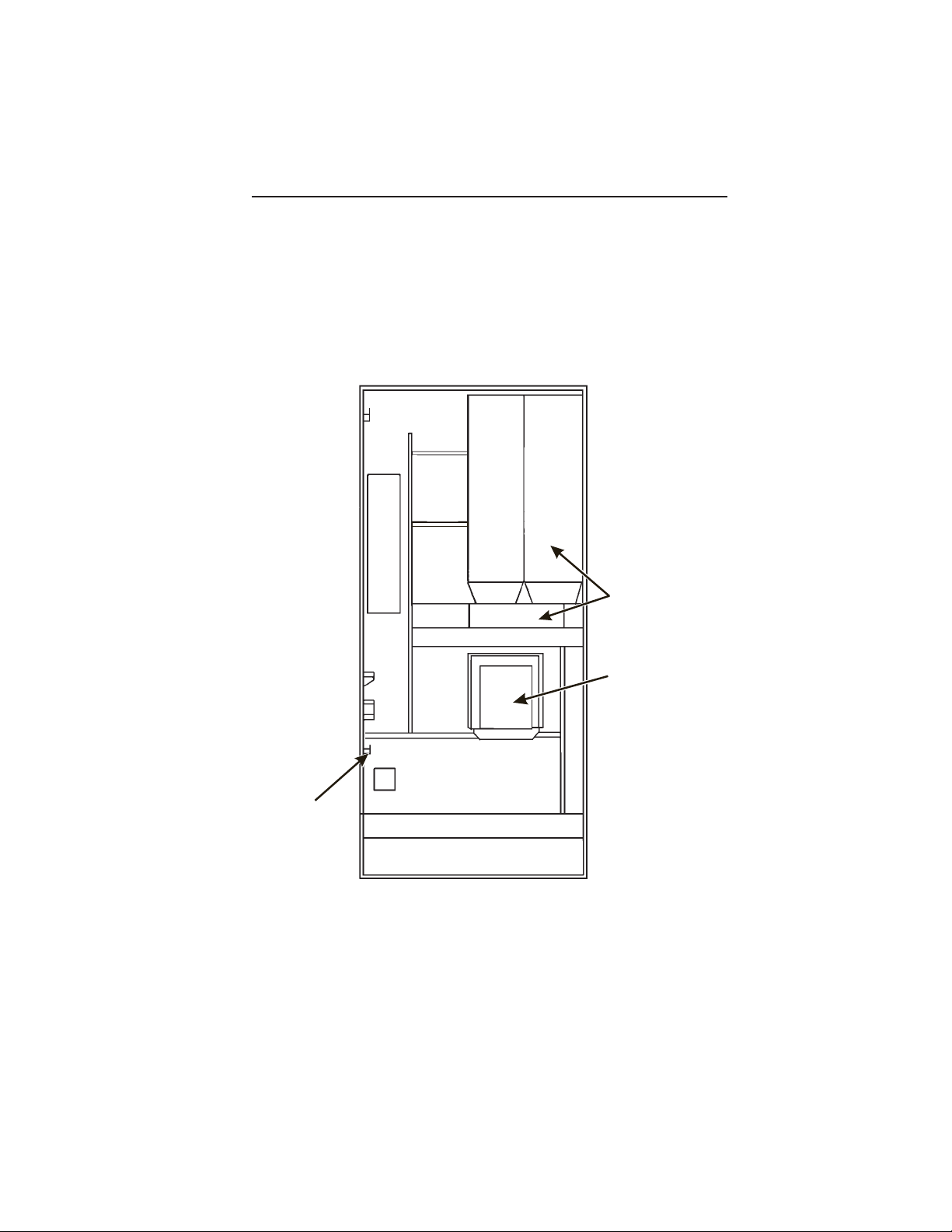
MAJOR PARTS
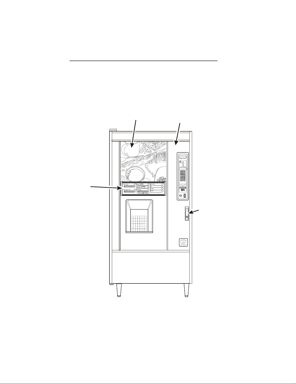
The diagrams on the following pages will acquaint you with the major parts of the
EuroDrink merchandiser. For more detailed information, please consult your PARTS
MANUAL. If you do not have a PARTS MANUAL, contact National Vendors Parts
Department.
MAJOR PARTS
MENU
ASSEMBLY
POINT OF
PURCHASE
PHOTO
˜
EXTERIOR
DOOR
ASSEMBLY
˜
CRANE
NATIONAL VENDORS
LOCK
FRONT OF MERCHANDISER
July, 2001 Page - vi 6360052
Page 9
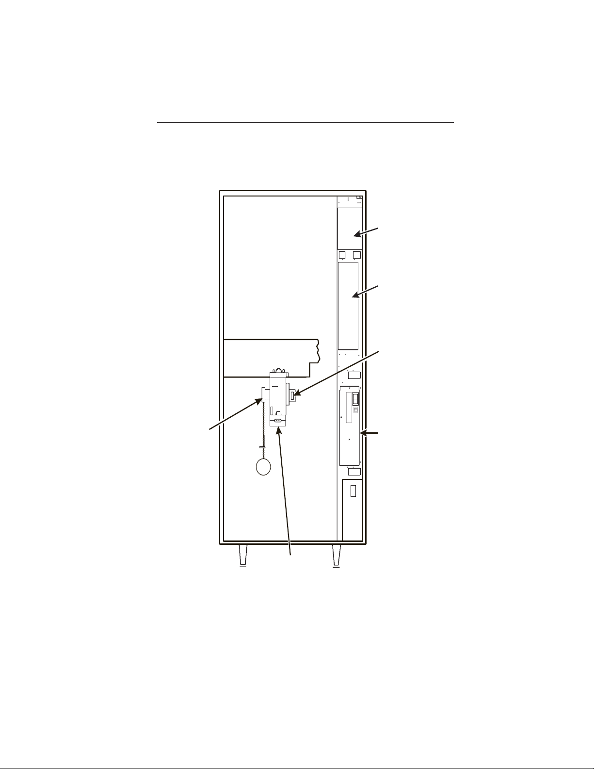
EURODRINK OPERATOR'S GUIDE
CUP MECHANISM
TURRET ASSEMBLY
AND MOTOR AND PCB
ASSEMBLY
DELIVERY DOOR
LOCK BAR
ASSEMBLY
BACK SIDE OF MERCHANDISER DOOR
6360052 Page - vii July, 2001
Page 10
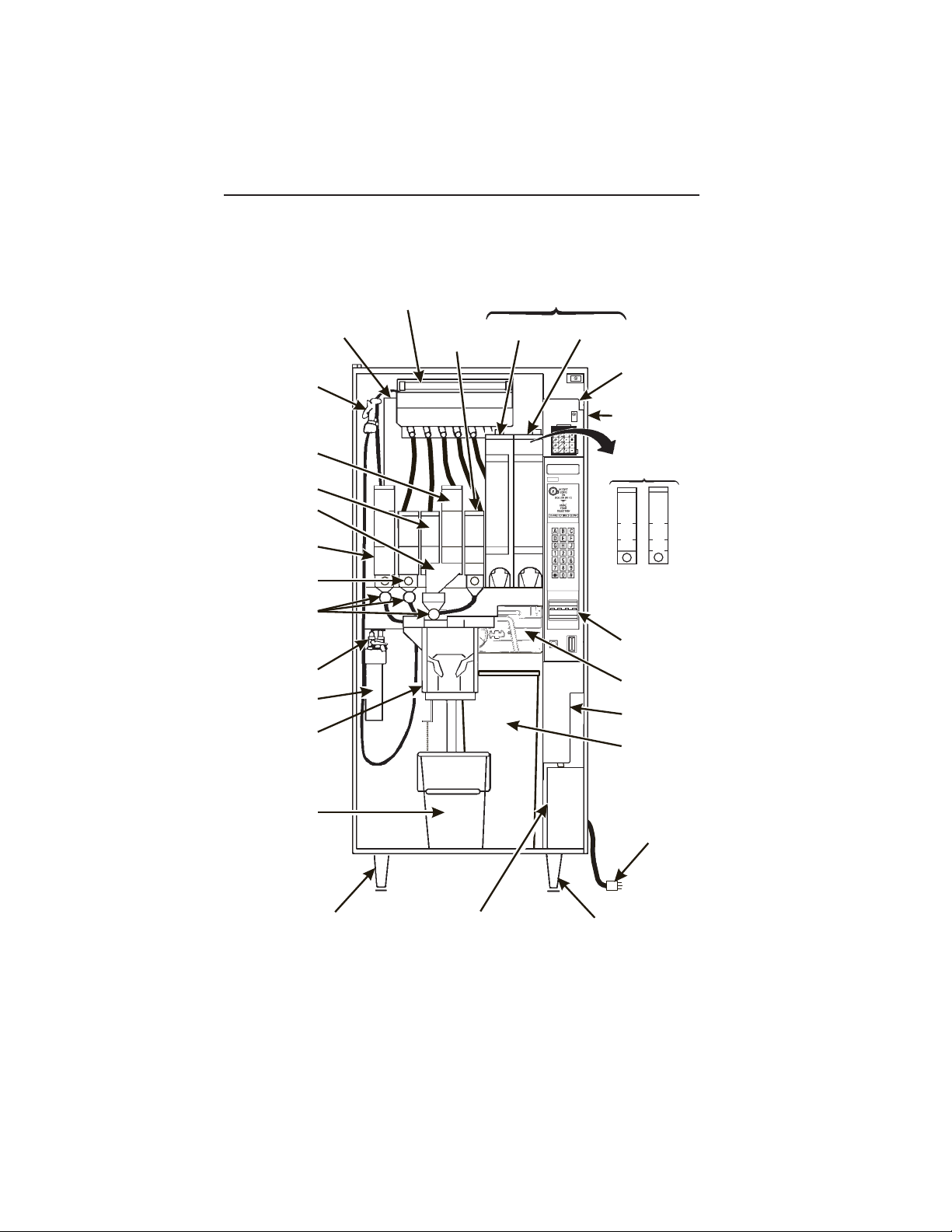
EURODRINK OPERATOR'S GUIDE
RINSE
HOSE
ASSEMBLY
SUGAR
CANISTER
LIGHTENER
CANISTER
TWO INGREDIENT
CHUTE
CHOCOLATE
CANISTER
SOUP OR SUGAR
SUBSTITUTE
CANISTER
DRINK WHIPPER
ASSEMBLY
FILTER & VALVE
HEAD ASSEMBLY
WATER FILTER
CARTRIDGE
CUP DELIVERY
ASSEMBLY
WATER TANK
ASSEMBLY
SERVICE LIGHT
ASSEMBLY
CANISTER
F.D. TEA
( OPTIONAL )
F.B. DECAF
CANISTER
F.B. COFFEE
CANISTER
NATIONAL VENDORS
CRANE
MONETARY
PANEL
ASSEMBLY
CABINET
( OPTIONAL )
F.D. CANISTERS
C
C
D
D
O
O
E
E
F
F
C
C
F
F
A
A
E
E
F
F
E
E
BILL
ACCEPTOR
(OPTIONAL)
BREWER
(OPTIONAL)
COIN
MECHANISM
GROUNDS
PAIL
LIQUID
WASTE
PAIL
LEG, HINGE, &
LEVELER ASSEMBLY
COIN BOX
ASSEMBLY
POWER CORD
&
PLATE ASSEMBLY
LEG & LEVELER
ASSEMBLY
MERCHANDISER CABINET INTERIOR
July, 2001 Page - viii 6360052
Page 11
EURODRINK OPERATOR'S GUIDE
MAIN
CONTROLLER
I
O
PCB ASSEMBLY
INTERFACE
BOARD
EXHAUST
FAN
BRACKET
ASSEMBLY
˜
˜
OVERFLOW
SWITCH
ASSEMBLY
OPTIONAL INFRARED
CUP/MUG SENSOR
POWER
PANEL
ASSEMBLY
MERCHANDISER CABINET INTERIOR
6360052 Page - ix July, 2001
Page 12
EURODRINK OPERATOR'S GUIDE
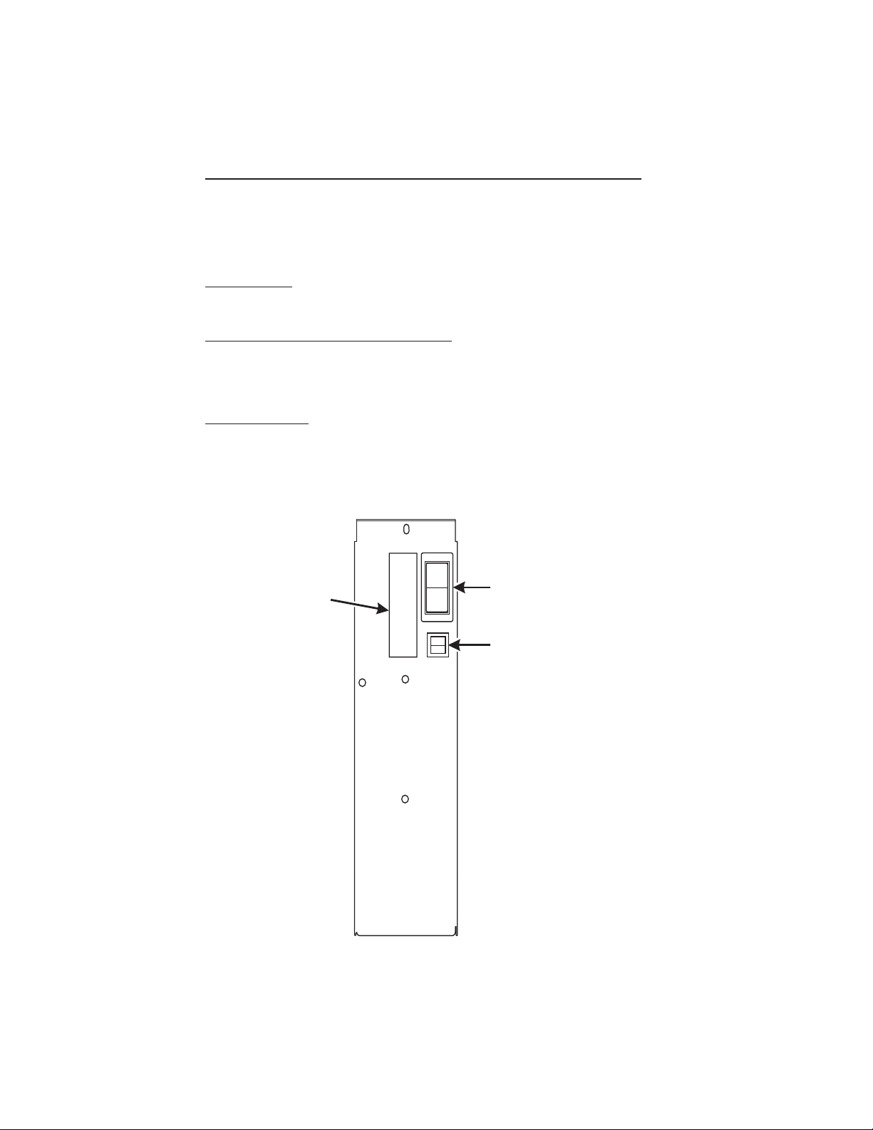
CONTROLS AND INDICATORS
POWER PANEL. You may have one of three power panels, depending upon where you
live. The controls are fundamentally the same, however.
Circuit Breakers. Circuit breakers protect the merchandiser against failures in the power
supply or any of the electrical components. If a circuit breaker trips and cannot be reset,
consult your troubleshooting manual.
Back Side of U.S./ Canada Power Control Panel. The circuit board mounted on the rear
of the U.S. and Canadian power control panel is a dc power supply for the coin
mechanism. A fuse protects the board circuitry in the event of a coin mechanism solenoid
failure. If the coin mechanism is not working, check this fuse. If the fuse is blown, a bad
coin mechanism solenoid could be at fault.
Main Power Switch. This is the main ON/OFF switch for the merchandiser.
CONTROLS AND INDICATOR S
To protect against electrical shocks and possible damage to the
machine, turn this switch OFF when performing any maintenance on the merchandiser.
WARNING
I
MAIN
POWER
LABEL
O
SWITCH
ELECTRONICS
BREAKER
626P0005
July, 2001 Page - x 6360052
Page 13
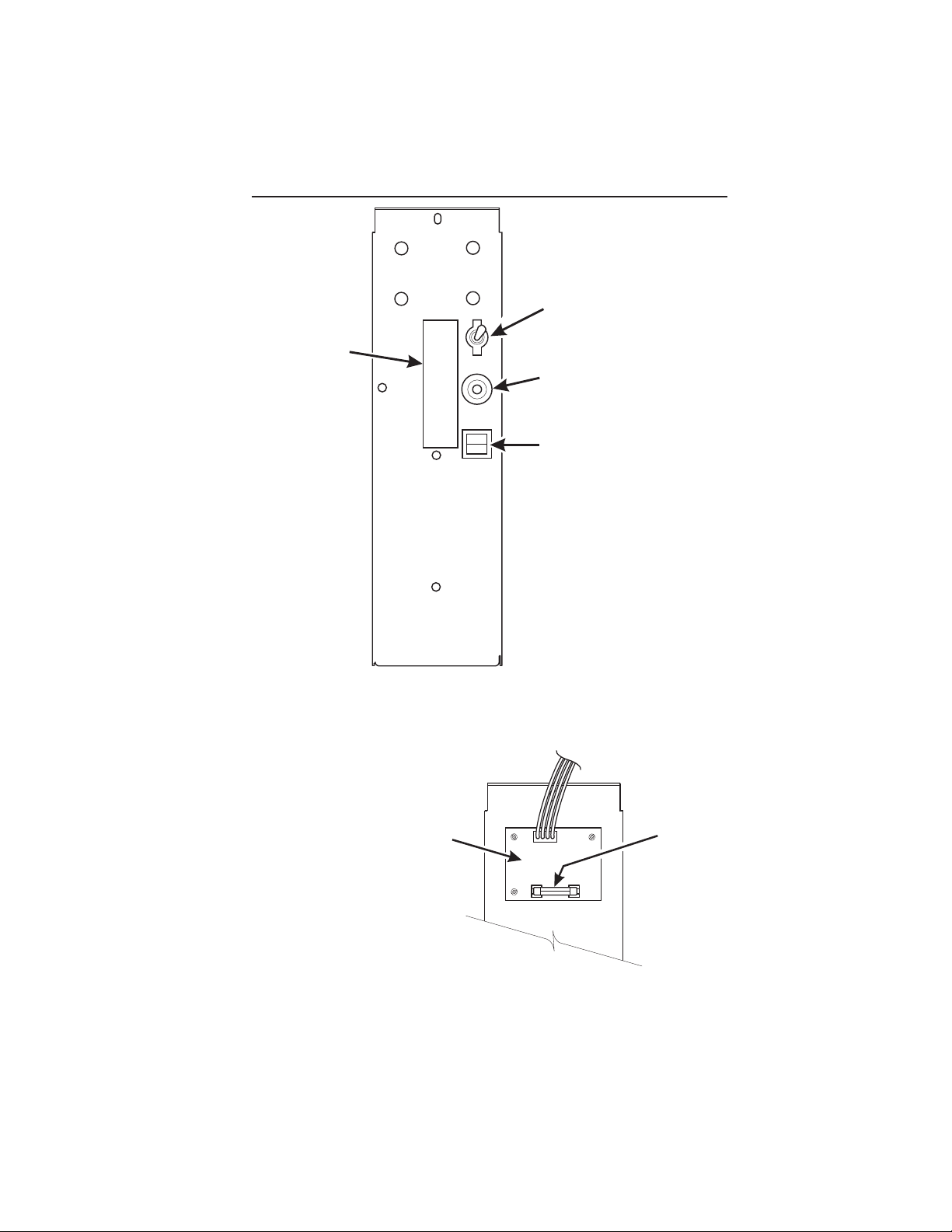
LABEL
EURODRINK OPERATOR'S GUIDE
MAIN
ON
OFF
POWER
SWITCH
MAIN
CIRCUIT
BREAKER
LOW VOLTAGE
CIRCUIT BREAKER
626P0006
POWER CONTROL PANEL
(U.S./CANADA)
TOP
DC POWER
SUPPL Y PCB
FOR 110V COIN MECH
BACK SIDE OF U.S./CANADA POWER CONTROL PANEL
6360052 Page - xi July, 2001
˜
AGC 1
FUSE
1 AMP
Page 14
EURODRINK OPERATOR'S GUIDE
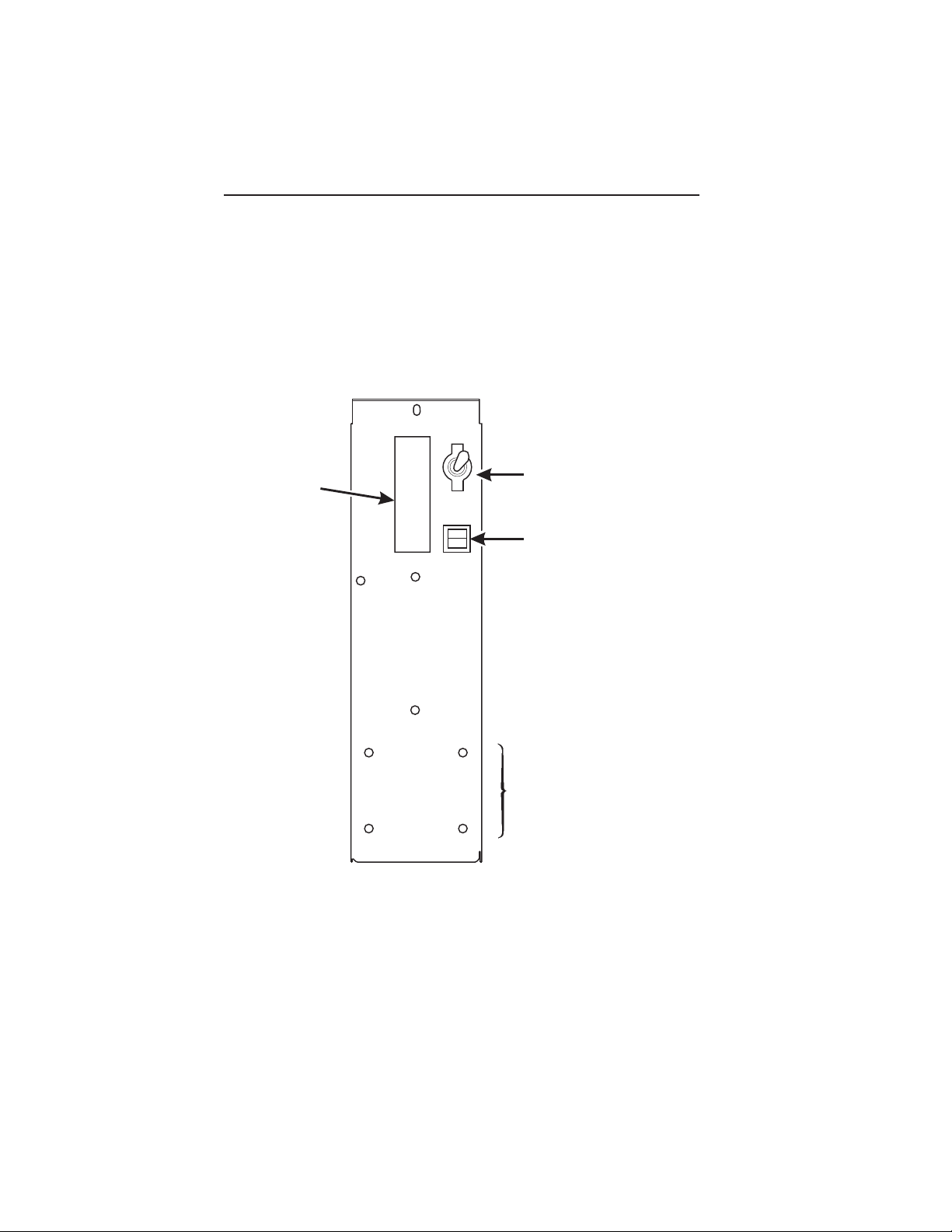
ON
LABEL
OFF
MAIN POWER
SWITCH
ELECTRONICS
CIRCUIT BREAKER
MOUNTING STUDS
FOR MEXICO ONLY
POWER CONTROL PANEL
(U.K. / MEXICO)
July, 2001 Page - xii 6360052
Page 15
EURODRINK OPERATOR'S GUIDE
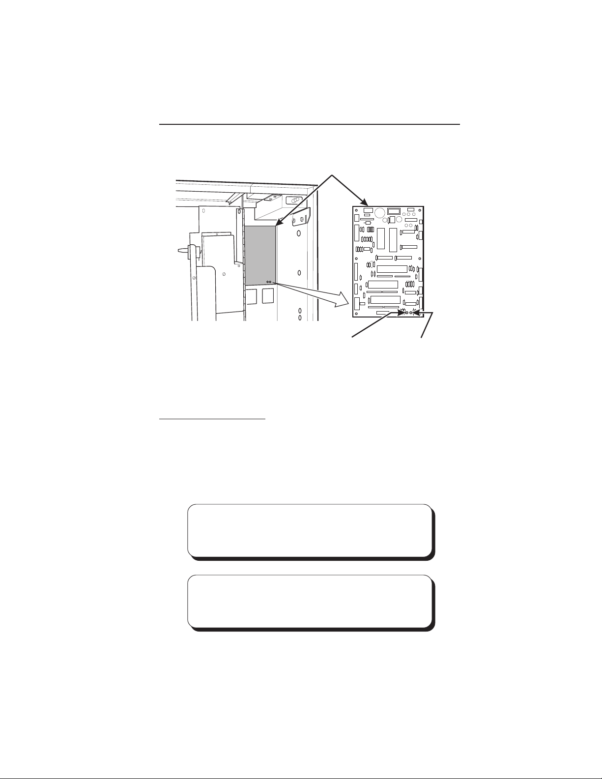
MAIN CONTROLLER
PCB ASSEMBLY
LED1LED2
POWER ON
(LED 1)
FLASHING
HEARTBEAT
(LED 2)
MAIN CONTROLLER PCB DISPLAY
Main Controller PCB Display. This display consists of two light emitting diodes (LED)
mounted on the controller PCB.
POWER ON When lit, this red LED indicates electrical power is applied to
(LED 1) the controller PCB.
HEARTBEAT When flashing, this red LED indicates that the controller PCB is
(LED 2) active, and the software is operating.
NORMAL CONDITIONS:
When the merchandiser is operating normally, you should see a
steady red POWER ON indicator. The red HEARTBEAT indicator
should be flashing with a balanced on/off pattern (on for the same
length of time that it is off).
ERROR CONDITIONS:
If an error is present, the red HEARTBEAT indicator will flash with
an unbalanced on/off pattern (on longer than it is off). The error(s)
can be viewed under the DIAGNOSTICS mode.
6360052 Page - xiii July, 2001
Page 16
EURODRINK OPERATOR'S GUIDE
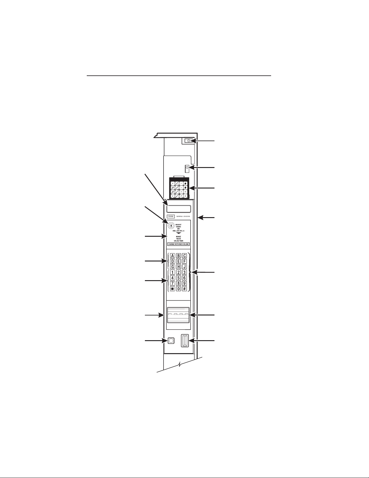
HIGH VOLTAGE
INTERLOCK
SWITCH
MESSAGE
DISPLAY
FREE VEND
KEYSWITCH
(OPTIONAL)
INSTRUCTION
PLATE
LETTERS
A-H,J
NUMERALS
1-9, *,0, #
MONETARY
PANEL
COIN
RETURN
BUTTON
LOW VOLTAGE
DOOR SWITCH
SERVICE
KEYPAD
CABINET
SELECTION
SWITCH
BILL
ACCEPTOR
(OPTIONAL)
COIN
INSERT
MONETARY PANEL
July, 2001 Page - xiv 6360052
Page 17
EURODRINK OPERATOR'S GUIDE
High Voltage Interlock Switch (U.S./ Canada). When the cabinet door is open, this
switch turns off the optional fan and bean light (if equipped), and turns on the service light.
High Voltage Interlock Switch (International). When the cabinet door is open, this
switch turns off all high voltage to the cabinet. Pulling the switch out restores high voltage
for maintenance purposes.
Low Voltage Door Switch. Informs the controller software of the main door open or
closed status.
Message Display. This is how the merchandiser communicates with the outside world.
Customers can see messages about how much money they have put into the merchandiser. The message display also tells customers when a selection is sold out and when
vending is free, inhibited, or discounted. The message display shows you what you are
doing when you program the merchandiser, and can show you what is wrong if there is
a failure.
Free Vend Keyswitch. This allows someone (other than maintenance people) to set the
merchandiser to free vend without opening the door.
Selection Switch Panel. The customer uses these switches to make selections. Also,
maintenance people may use this switch panel during programming and other support
modes.
Coin Return Button. Pressing this button returns any coins that have been paid into the
merchandiser prior to a vend.
Bill Acceptor (Optional). Accepts bills in various denominations, depending upon the
type of bill validator, and how the machine is configured.
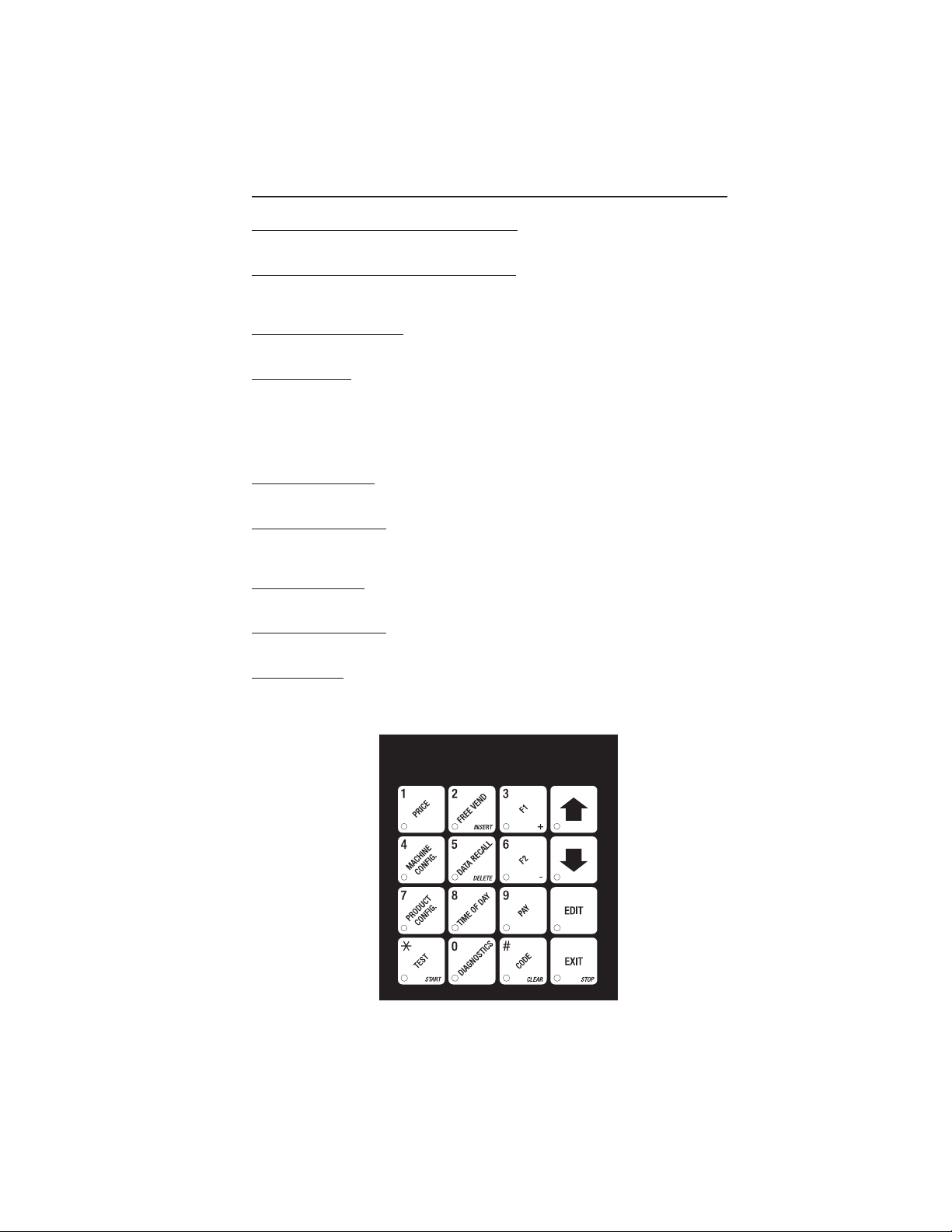
Service Keypad. The service keypad is located at the top of the monetary panel. It gives
service personnel the means to program, retrieve data from, and view diagnostic
information about, the merchandiser.
SERVICE KEYPAD
6360052 Page - xv July, 2001
Page 18

EURODRINK OPERATOR'S GUIDE
THIS PAGE INTENTIONALLY LEFT BLANK
July, 2001 Page - xvi 6360052
Page 19
EURODRINK OPERATOR'S GUIDE
INITIAL SET-UP
I. LOCATION PREPARATION
After your machine is unpacked and placed near its permanent location, you need to
make sure you have the proper electrical and water service.
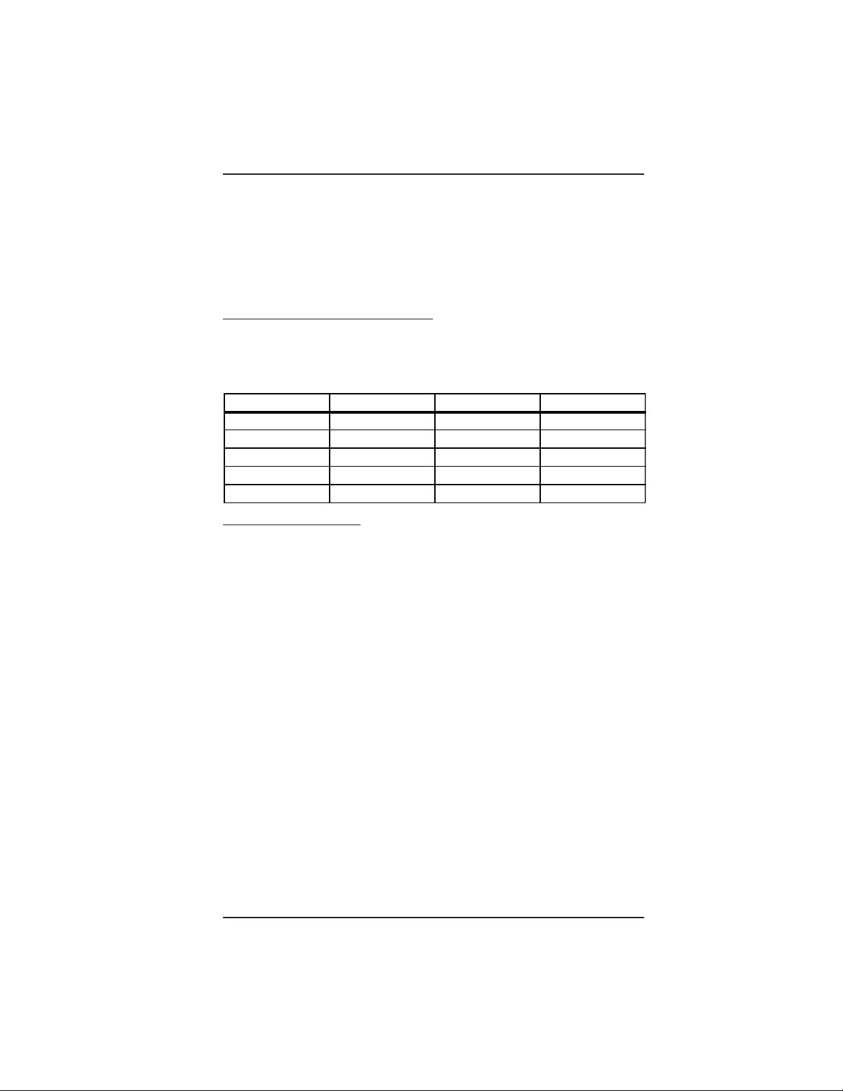
ELECTRICAL POWER REQUIREMENTS
This merchandiser needs electrical power as shown in the following table. NOTE: Each
merchandiser should have its own electrical circuit.
Power Requirements
Country Volts Frequency (Hz) Current (Amps)
Canada 115 60 15
France 230 50 10
Germany 230 50 10
United Kingdom 230 50 10
United States 115 60 15
1. Check the Power Outlet
This merchandiser is supplied with a service cord for the country of use and is
terminated in a grounding type plug. The wall receptacle used for this merchandiser
must be properly polarized, grounded, and of the correct voltage. Operating the
merchandiser from a source of low voltage will VOID YOUR WARRANTY. Each
merchandiser should have its own electrical circuit and that circuit should be protected
with a circuit breaker or fuse conforming to local regulations.
Voltage Check - Place the leads of a voltmeter across the LINE (LIVE) and
NEUTRAL terminals of the wall receptacle. The voltmeter should indicate 110-130
volts ac for 120 volt, 60 Hz locations, or 220-240 volts ac for 230 volt, 50 Hz
locations.
Polarity Check - Place the leads of a voltmeter across the LINE (LIVE) and
GROUND terminals of the wall receptacle. The voltmeter should indicate 110-130
volts ac for 120 volt, 60 Hz locations, or 220-240 volts ac for 230 volt, 50 Hz
locations.
Noise Potential Check - Place the leads of a voltmeter across the NEUTRAL and
GROUND terminals of the wall receptacle. The voltmeter should indicate 0 volts
ac. A measurement greater than 1.5-2.0 volts ac could result in problems for the
merchandiser's electronic circuitry caused by electrical noise.
Any deviation from these requirements could result in unreliable performance from
your merchandiser.
6360052 Page - 1 July, 2001
Page 20

EURODRINK OPERATOR'S GUIDE
WATER REQUIREMENTS
The best type of water for coffee brewing is normal hard (tap) water. If your location
has chemically softened water, you should do one of the following things:
•Have a non-softened supply line run to the merchandiser
•Contact your local water filter supplier for information and suggestions
Well water can also be used in the EuroDrink Machine. However, you should
have it checked for levels of carbonates and alkalies. Contact your water filter
supplier if these values are relatively high.
What is the Water Pressure at Your Location?
It should be no less than: 10 psi ( 69.0 KPa) at 1/2 gallon/minute
And no more than: 80 psi (522.0 KPa) at 1/2 gallon/minute
If you're not sure about the pressure and flow rate, check with your water company.
What to do With the Water Supply Line:
Locate the supply line at the rear of your merchandiser.
Equip the line with a shut-off valve.
Flush the water supply line before connecting it to the merchandiser. A minimum of five
gallons is usually required before connecting the merchandiser to the supply line. DO
NOT flush the merchandiser water system. If you do, you might introduce water line
contaminants into the merchandiser.
July, 2001 Page - 2 6360052
Page 21

EURODRINK OPERATOR'S GUIDE
II. POSITIONING THE
MERCHANDISER
You can position this merchandiser anywhere in a bank of machines. It can even be
placed on the end flush against a side wall. Be sure you leave enough room in front
of the merchandiser for the door to move freely.
BE SURE THE REAR OF THE MERCHANDISER IS AT LEAST 6"
AWAY FROM THE WALL. THIS WILL ALLOW WARM MOIST AIR
TO BE VENTED OUT OF THE MACHINE'S INTERIOR.
THIS MACHINE IS ONLY RATED FOR INSTALLATION IN AN
INDOOR LOCATION.
WARNING:
III. CONNECTING EVER YTHING
1. Connect the Merchandiser to the Water Supply:
a. You will need the following:
• A coil of copper tubing with outside diameter of 3/8 inch (9.5 mm) or greater. The
appropriate plastic tubing may be substituted. The tubing must be long enough
to reach from the water source to your machine with enough left over to form a
loop about 2 feet (60 cm) in diameter. This will allow you to move the machine
without straining the water line.
• A 3/8 inch (9.5 mm) flare fitting.
b. Connect the merchandiser to your water supply.
2. Connect the Merchandiser to the Electrical Power Supply:
Power inside the merchandiser is controlled by the main power switch, located on the
power panel.
a. Make sure the main power switch is OFF.
b. Connect the merchandiser’s power cord to your wall outlet.
6360052 Page - 3 July, 2001
Page 22
EURODRINK OPERATOR'S GUIDE
IV. FINAL MECHANICAL
PREPARATION
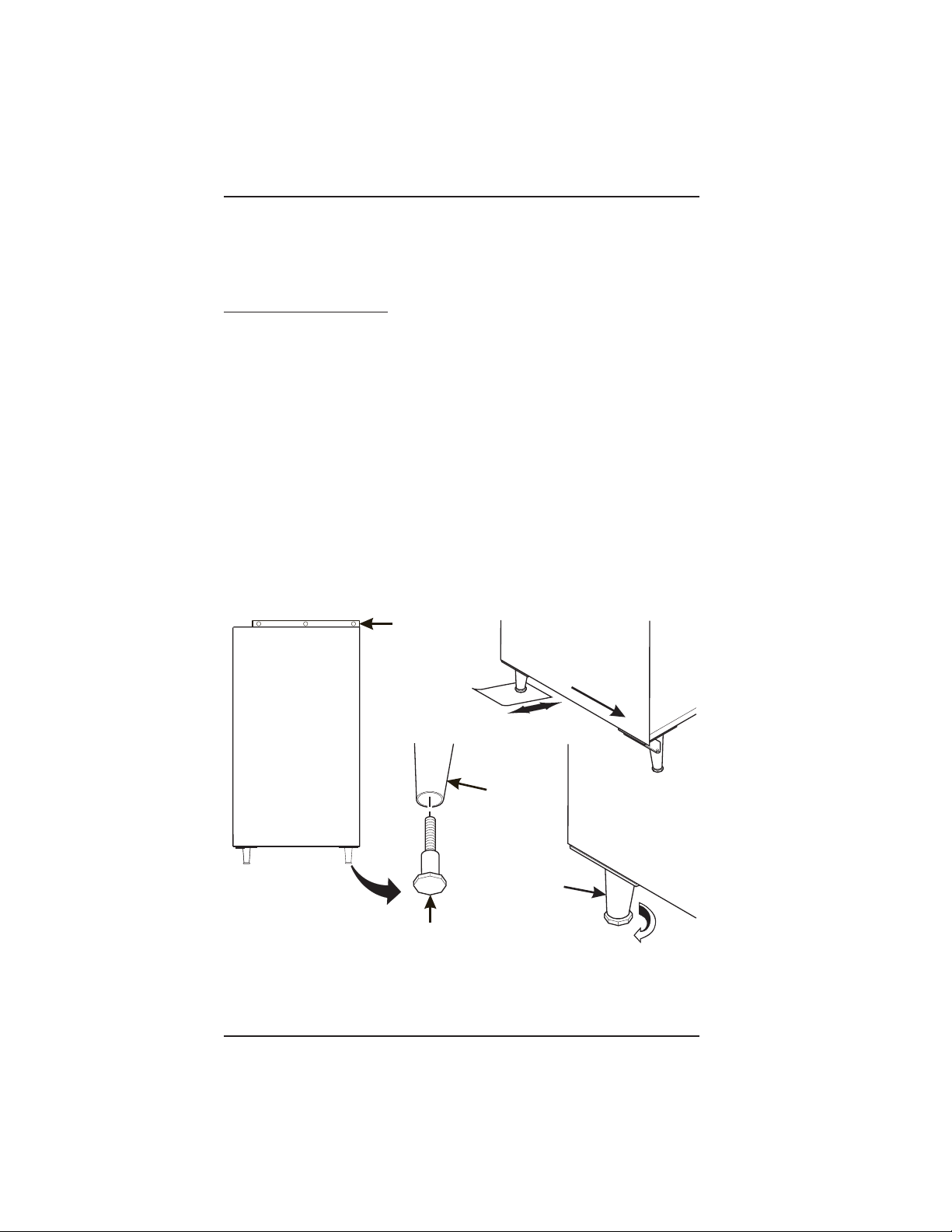
1. Level the Merchandiser:
a. Place a spirit level on the top front edge of the cabinet with the door fully closed.
Adjust the front legs only until the cabinet is reasonably level.
b. Hold the door open about 4 inches.
HAVE AN ASSISTANT HOLD THE MERCHANDISER WHILE
YOU ADJUST THE LEG LEVELERS.
c. Adjust the back legs so that the back leg leveler on the hinge side is off the floor
just enough so a piece of paper can slide under it with only a bit of resistance.
d. For proper weight distribution on all four legs, raise the back leg on the hinge
side by unscrewing the leveler 1½ turns.
You may need to use pliers or channel locks to loosen the leg
levelers.
WARNING
NOTE
SPIRIT LEVEL
FRONT
LEG
LEFT REAR
LEG
LEG
LEVELER
July, 2001 Page - 4 6360052
1-1/2 TURNS
Page 23
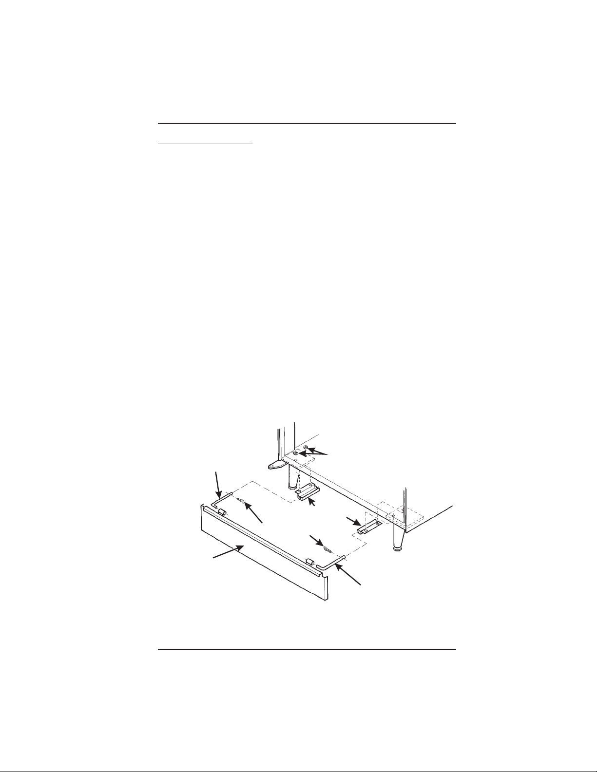
2. Mount the Base Plate:
EURODRINK OPERATOR'S GUIDE
DO NOT MOVE THE CABINET WHILE HEX
HEAD SCREWS AND/OR CARRIAGE
BOLTS ARE LOOSENED. THE CABINET
WOULD BECOME UNSTABLE AND LIKELY TO TIP AND CAUSE INJURY.
a. Remove the pail(s) from the inside of the merchandiser.
b. Remove the floor liner from the inside of the merchandiser.
c. Remove the two caps as shown.
d. Loosen the left leg assembly carriage bolts and nuts to allow mounting a base plate
bracket.
e. Secure one of the base plate brackets to the leg assembly using the two carriage
bolt. Tighten the carriage bolts and nuts.
f. Loosen the right leg assembly hex head screws to allow mounting the other base
plate bracket.
g. Secure the other base plate bracket to the right leg assembly using the two hex
head screws. Tighten the hex head screws.
h. Insert the short arms of the slides into the hinged tabs of the base plate. Position
the slide so the notch near the short arm is on the bottom side.
i. Insert the long arms of the slides into the base plate brackets.
j. Insert and secure a cotter pin through the hole in the back of each of the slides.
k. Push the base plate toward the merchandiser cabinet. The front tabs of the base
plate brackets should seat in the notches in the long arms of the slides.
l. Replace the caps, liner, and pail(s) removed previously.
WARNING
CAPS
SLIDE - L.H.
BASE PLATE BRACKET
COTTER PIN
BASE PLATE
ASSEMBLY
SLIDE - R.H.
6360052 Page - 5 July, 2001
Page 24
EURODRINK OPERATOR'S GUIDE
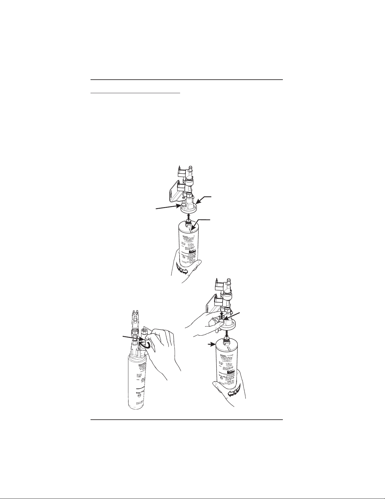
3. Install the Water Filter Cartridge:
IF YOUR MERCHANDISER HAS THE WATER FILTER OPTION,
IT CANNOT BE OPERATED WITHOUT A PROPERLY INSTALLED WATER FILTER CARTRIDGE. If you do not have the
water filter option, continue with "Fill the Tank".
CUNO BRAND ...
Check the water filter installation record. There
is a place to write the vend number on the
cartridge. The cartridge is effective for a max-
FILTER
LOCKING
TAB
TO INSTALL
THE FILTER:
1. INSERT NEW FILTER,
ROTATE COUNTERCLOCKWISE UNTIL
FILTER LOCKING TAB
SNAPS INTO GROOVE
AS SHOWN.
NOTE
imum of 64,000 7 oz. vends, 56,000 8
oz. vends, 50,000 9 oz. vends, or 37,000
12 oz. vends. Local conditions may
require more frequent replacement.
CUNO FILTER
HEAD ASSEMBLY
GROOVE
1. CLOSE THE WATER SHUT
-OFF VALVE BY TURNING
THE KNOB TO THE
HORIZONTAL POSITION
AS SHOWN.
WATER
SHUT-OFF
KNOB
TO REMOVE FILTER:
2. LIFT THE FILTER
LOCKING TAB,
ROTATE FILTER
CLOCKWISE AND
PULL DOWN AS
SHOWN.
CUNO
FILTER
FILTER
LOCKING
TAB
July, 2001 Page - 6 6360052
Page 25
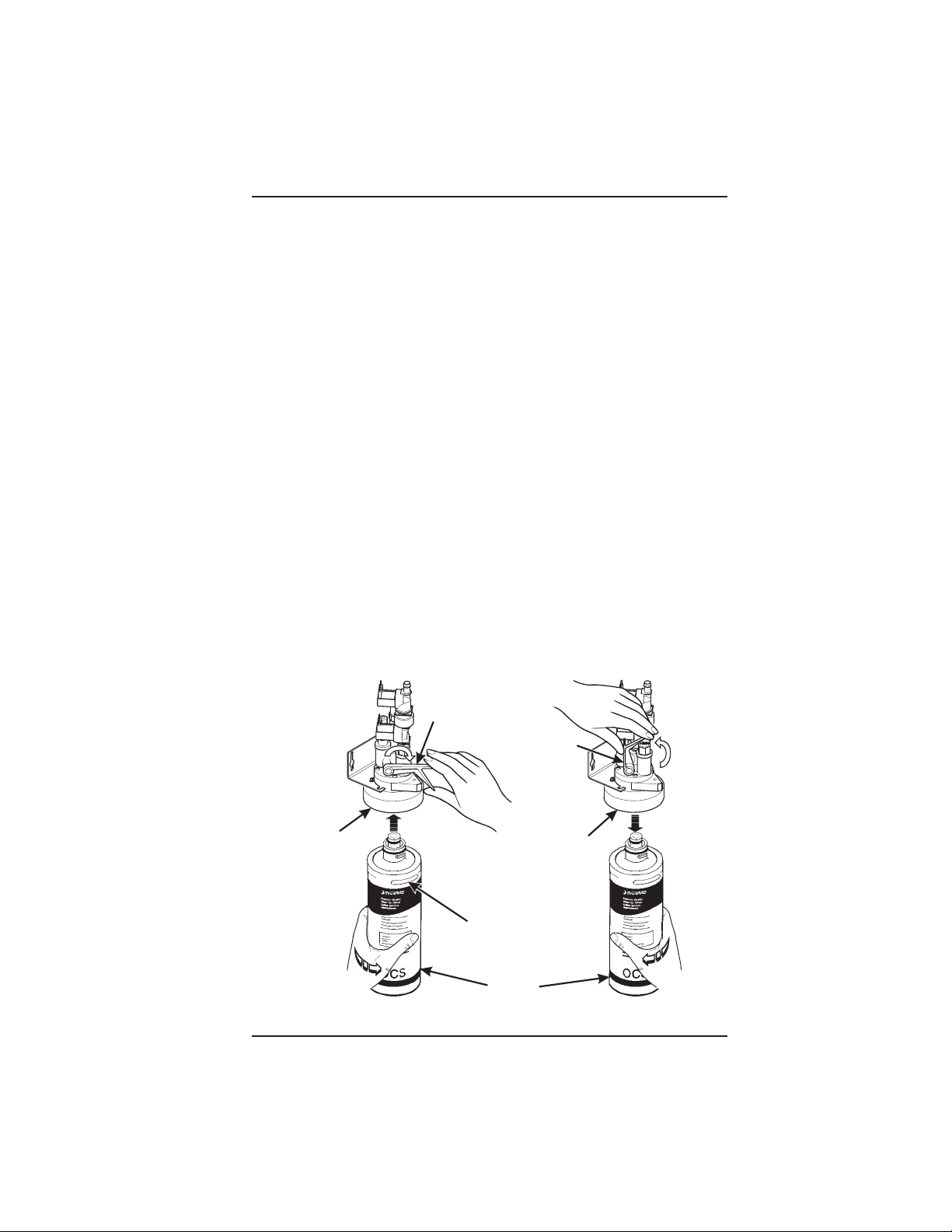
EVERPURE BRAND ...
EURODRINK OPERATOR'S GUIDE
Check the water filter installation record. There is a place to write
NOTE
the vend number on the cartridge. The cartridge is effective for a
maximum of 26,000 7 oz. vends, 22,000 8 oz. vends, 20,000 9 oz.
vends, or 15,000 12 oz. vends. Local conditions may require more
frequent replacement.
National Vendors recommends that you do the following procedure the first time you
fill the tank in your EuroDrink merchandiser:
a. Remove the small inner "O" ring from the filter cartridge.
b. Install the filter cartridge.
c. Turn on the water at its source, and perform the tank filling procedure.
d. Turn off the water at its source, remove the filter cartridge, and replace the "O"
ring.
e. Install the filter cartridge.
TO INSTALL FILTER:
1. ALIGN RAISED RIB ON
FILTER CARTRIDGE WITH
MATING SLOT IN HEAD
ASSEMBLY.
2. FIRMLY INSERT FILTER
CARTRIDGE INTO HEAD
ASSEMBLY AND ROTATE
COUNTER-CLOCKWISE
1/4 TURN TO THE STOP.
3. OPEN THE WATER SHUT-OFF
VALVE BY PUSHING THE
HANDLE TO THE HORIZONTICAL
POSITION AS SHOWN BELOW.
TO REMOVE FILTER:
1. CLOSE THE WATER SHUT-OFF
VALVE BY LIFTING THE HANDLE
TO THE VERTICAL POSITION AS
SHOWN BELOW.
2. ROTATE THE FILTER
CLOCKWISE AND PULL
DOWN AS SHOWN.
WATER SHUT-OFF
VALVE HANDLE
WATER SHUT-OFF
VALVE HANDLE
EVERPURE
FILTER HEAD
ASSEMBLY
RAISED
RIB
FILTER HEAD
EVERPURE
FILTER
CARTRIDGE
EVERPURE
ASSEMBLY
6360052 Page - 7 July, 2001
Page 26
EURODRINK OPERATOR'S GUIDE
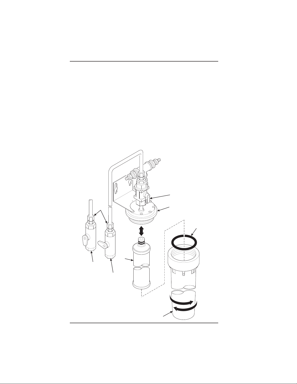
HYDROLIFE BRAND
INSTALLATION:
1. Place the filter inside the canister. Be sure the o-ring is seated in the canister just
below the threads.
2. Screw the canister and filter assembly onto the filter head until it comes to a stop.
3. Open the water valve on the inlet line by rotating the handle to the vertical position
as shown.
REMOVAL
1. Close the valve on the inlet line by rotating the handle into the horizontal position
as shown.
2. Relieve water pressure by performing two or three water throws (see the programming section).
3. Unscrew the filter and canister assembly from the filter head. Remove the filter
from the canister.
OPEN
POSITION
INSTALL
HYDROLIFE
FILTER HEAD
O-RING
REMOVE
OPEN
POSITION
VALVE
CLOSED
POSITION
FILTER
CANISTER
July, 2001 Page - 8 6360052
Page 27
EURODRINK OPERATOR'S GUIDE
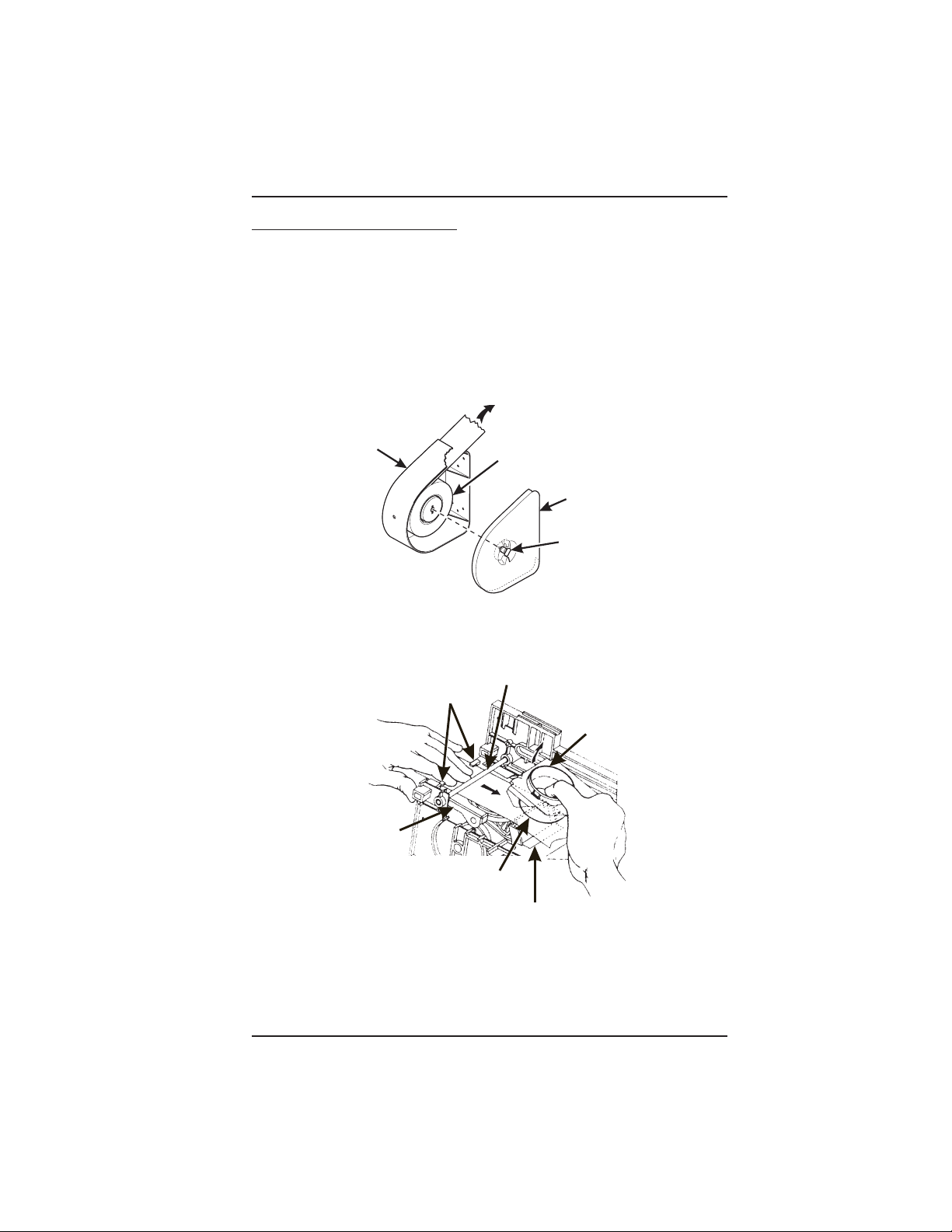
4. Load the Optional Filter Paper:
a. Be sure the main power switch is in the OFF position.
b. Remove the cup station and grounds bucket.
c. Remove the paper holder cover by turning the fastener a quarter turn to the left.
d. Insert a roll of paper into the paper holder. Route the free end of the paper to the
brewer as shown.
e. Replace the cover on the paper holder. Secure it by turning the fastener a quarter
turn to the right.
f. Feed paper over swing arm assembly and underneath pinion gear shaft.
TO BREWER
PAPER
HOLDER
g. Feed paper through the paper guides.
h. Raise the basket housing assembly and feed paper over the lip of the paper
mechanism housing.
PAPER
GUIDES
SWING ARM
ASSEMBLY
LIP OF PAPER MECHANISM HOUSING
PAPER
ROLL
COVER
FASTENER
PINION GEAR SHAFT
BASKET HOUSING
ASSEMBLY
PAPER MECHANISM HOUSING
It may be necessary to reach underneath the brewer between the
paper mechanism housing and swing arm assembly to push paper
over the lip of the paper mechanism housing.
CONTINUED . . .
6360052 Page - 9 July, 2001
NOTE
Page 28
EURODRINK OPERATOR'S GUIDE
LIP OF PAPER MECHANISM HOUSING
SWING ARM ASSEMBLY
PAPER MECHANISM HOUSING
i. Reach underneath the brewer between the paper mechanism housing and basket
housing assembly and push paper into the top of the paper mechanism housing
between paper rollers.
BASKET HOUSING ASSEMBLY
PAPER MECHANISM HOUSING
j. Reach underneath the brewer and pull paper roller to the right.
k. Pull paper down between the paper rollers.
l. Release the paper roller.
PAPER
ROLLER
July, 2001 Page - 10 6360052
Page 29
EURODRINK OPERATOR'S GUIDE
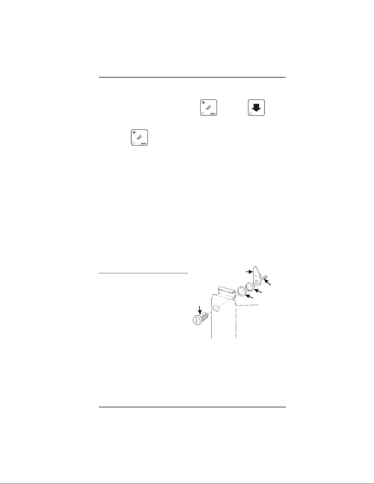
m. Place the main power switch in the ON position.
n. Test the brewer to be sure the paper feeds properly:
1. On the maintenance keypad, press , then press until the
display shows BREW TEST.
2. Press to test each brewer position:
Keep away from the brewer mechanism while it is operating.
Coming into contact with moving parts could injure you.
WARNING
BREW 'R BREW The brewer is in the BREW position.
BREW 'R FLIP The brewer is in the FLIP position.
BREW 'R HOME The brewer is in the HOME position.
3. Make sure the filter paper feeds properly without jamming.
o. Replace the cup station and grounds bucket.
5. Install the Optional Coin Box Lock
a. Install the lock cylinder, washer, and nut in
the order shown.
b. Tighten the nut.
c. Install the lock bar as shown,
and secure with the screw.
LOCK
CYLINDER
LOCK BAR
SCREW
NUT
WASHER
6360052 Page - 11 July, 2001
Page 30
EURODRINK OPERATOR'S GUIDE
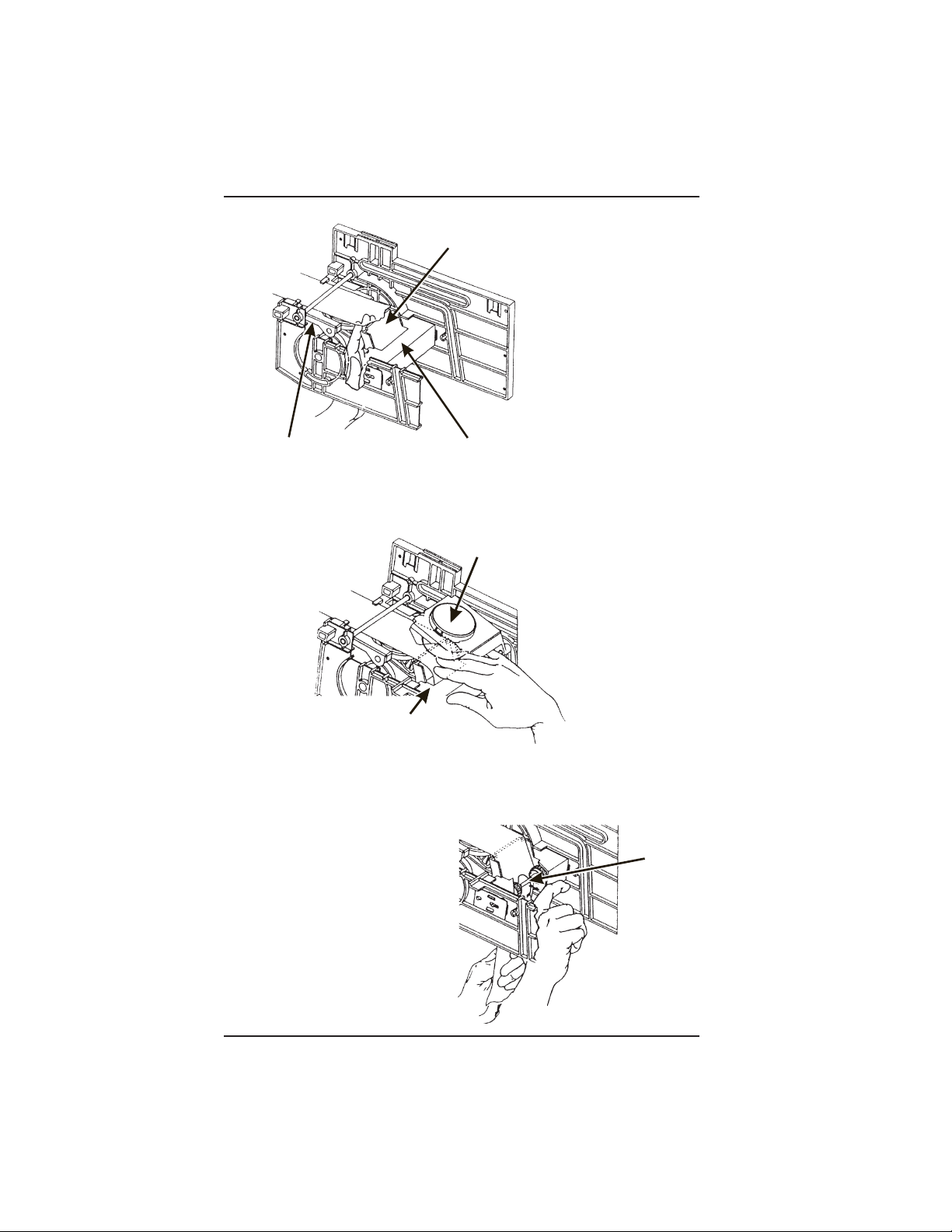
6. Set Up and Load the Coin Mechanism
24 PRODUCTS
Standard Coin Mechanism
18
Setting the Quarter Switch. If your coin
PRODUCTS
mechanism is not a MARS TRC 6000, skip
this procedure and begin LOADING THE
COIN MECHANISM.
a. Flip down the front of the coin mechanism as
shown, and set the quarter switch.
12
PRODUCTS
˜
VEND DOOR
(REF)
Load the Coin Mechanism.
a. Open the cabinet door and the monetary door.
b. Insert coins into their respective tubes until each tube has been filled.
c. Inspect the tubes for shingled coins and correct if necessary.
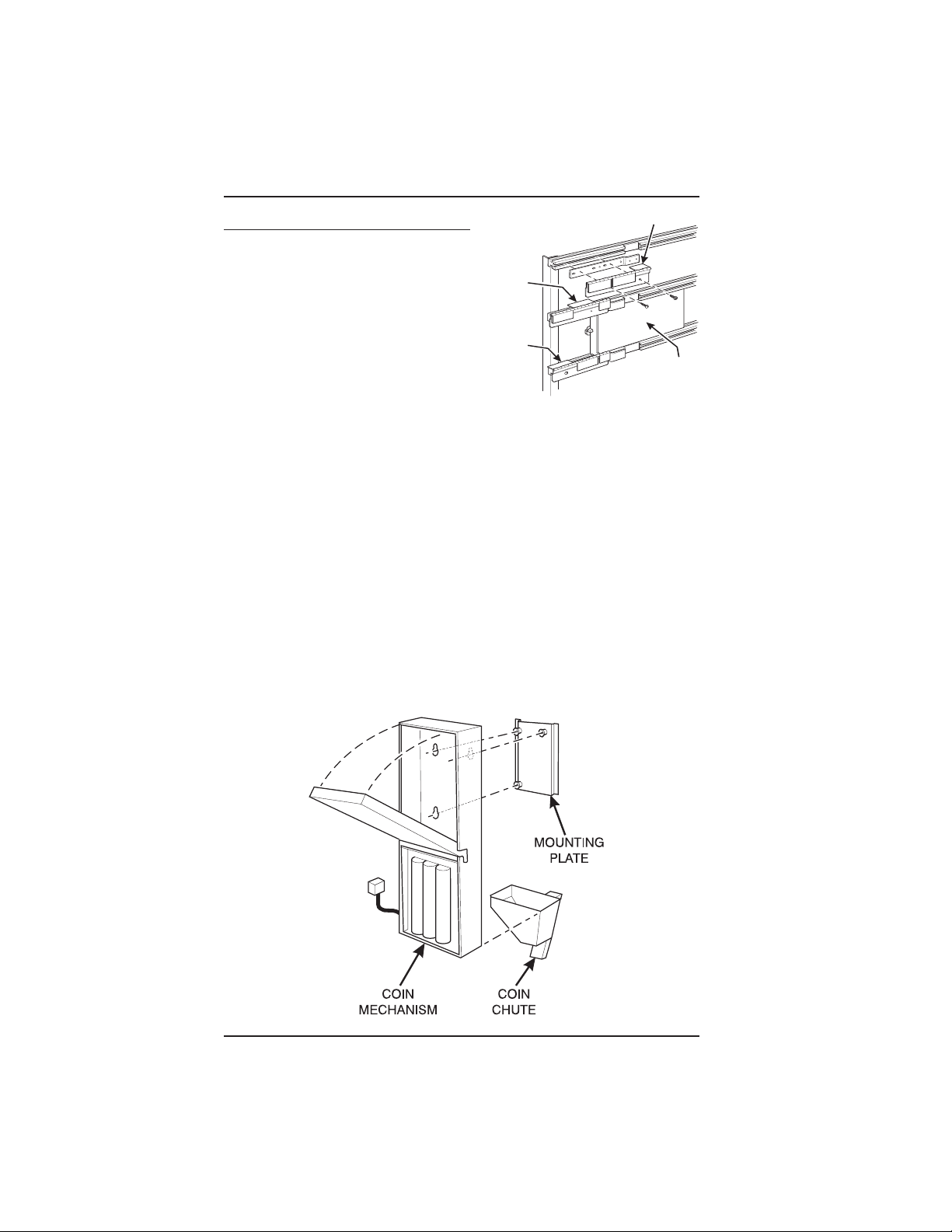
MDB Coin Mechanism
Install the coin mechanism as follows:
WARNING
Make sure the main power switch is turned OFF before you work
on the merchandiser. Failure to do so could result in death or
injury.
a. Turn OFF the main power switch. Refer to the instructions provided with the coin
mechanism and remove the coin validator assembly.
b. Loosen the coin mechanism mounting screws on the merchandiser so they stand
off about 1/8" (0.3 cm).
c. Position the coin mechanism so the three keyed holes fit over the mounting screws.
Pull down on the coin mechanism to seat the screws in the keyways.
d. Tighten the mounting screws and reinstall the coin validator assembly.
July, 2001 Page - 12 6360052
Page 31

EURODRINK OPERATOR'S GUIDE
e. The following figure shows a coin mechanism, bill validator, and card reader
connected to one another via an MDB. Some monetary configurations may not
include all of these devices. Connect your coin mechanism as shown:
f. Turn ON the main power switch. Select MDB MECH in the SELECT COIN
MECHANISM AND OPTIONS procedure on page 2-11. Press until the
standby message is displayed, then press . Insert enough coins through
the coin slot into the coin tubes to more than cover the empty sensor. Insert coins
one at a time and ensure they lay flat in the tubes. The amount of coins you insert
is internally recorded.
g. Payout about 6 coins to ensure proper loading.
h. Finish inserting coins through the coin slot to fill all the tubes with coins.
i. Visually check the coin tubes to make sure coins are not shingled.
6360052 Page - 13 July, 2001
Page 32

EURODRINK OPERATOR'S GUIDE
7. Fill the Tank:
a. Make sure the main power switch is ON.
b. Turn on the water at its source.
c. On the maintenance keypad, press , then press until the display
shows TANK.FILL.
d. Press . You should hear water running into the tank, and the display will
show FILLING. The water will run until either the tank is full or 12 minutes go by,
whichever happens first.
The inlet water valve only stays open for 12 minutes at a time. This
is a safety feature to prevent water from running into a leaky
system and making a mess. It is possible for your tank to take
longer than 12 minutes to fill if your location has low water
pressure. To be on the safe side, check for leaks if the water runs
a long time. If you find none, everything is normal; you just have
low water pressure.
e. When you hear the water stop running, repeat steps 3 and 4. Under normal
circumstances, nothing will happen. If water starts running and the display shows
NOTE
FILLING again, your pressure is low and it is just taking a long time to fill the tank.
Repeat this step if necessary to be sure your water tank is full.
8. Fill the Canisters:
Open the lid as shown, and carefully pour the
appropriate product into the canister. Repeat for all canisters in the machine.
FILL
CANISTER
CANISTER
CAP
July, 2001 Page - 14 6360052
Page 33

9. Load Cups:
EURODRINK OPERATOR'S GUIDE
Use only cups which have been designed for use in a hot
beverage vending machine.
a. Support the cup mechanism in the upright position.
b. Push the latch forward to release the cup mechanism. Continue to support the cup
mechanism while you lower it into the loading position.
c. Remove the turret cover.
OBSERVE PROPER HYGIENE - DO NOT TOUCH THE CUPS!
d. Open the bottom of the wrapper on a stack of cups.
e. Insert the wrapped cups into the turret and pull the wrapper out.
DO NOT FILL CUPS ABOVE THE LEVEL MARKED ON THE
OUTSIDE OF THE CUP TURRETS OR ABOVE THE “FILL LINE”
LABEL INSIDE EACH TURRET, OR MOTOR JAMS WILL OCCUR.
USE ONLY THE SAME SIZE AND BRAND OF HOT DRINK CUPS
IN EACH TURRET; DO NOT INTERMIX!
f. Replace the turret cover after the turrets have been loaded.
g. Be sure the cup mechanism is locked into the upright position.
10. Tell the Machine About the Cup Size(s):
Your Eurodrink merchandiser can vend two drink sizes, but it can only handle one
actual cup size at a time. Therefore, the cups you loaded must be able to contain both
drink sizes. You will need to "tell" the merchandiser which cup you have loaded into
it, plus what size you want for the smaller size drink.
CAUTION
a. Press , then press until the display shows CUP X OZ .
b. Press until the size of the regular drink is displayed. NOTE: The size must
be the same as or smaller than the cups you loaded.
c. Press , and the display shows CUP.1 X OZ.
d. Press until the size of the large drink is displayed. This size MUST BE THE
SAME AS than the cups you loaded!
6360052 Page - 15 July, 2001
Page 34

EURODRINK OPERATOR'S GUIDE
TURRET DESIGNATIONS
CUP STACK ROTATION
DOOR
1B 1A
CUP
MECHANISM
CABINET
DOOR
CUP MECH
MOUNTING
BRACKET
RETAINING
STRAP
TOP VIEW
LID
LOAD CUPS
HERE
CUP TURRET
LATCH
CUPS
TOP VIEW
July, 2001 Page - 16 6360052
Page 35

EURODRINK OPERATOR'S GUIDE
11. Test the Machine:
Your EuroDrink merchandiser is now ready to vend coffee, just as soon as the water
in the tank reaches its operating temperature. Press , and a reading of the tank
temperature is displayed. When the display shows 94° C (202° F), it is ready for
vending.
a. Close the door, make a selection, and enjoy your cup of coffee!
b. You will now need to do the following before your machine is ready to start earning
money:
• Set prices
• Set up the menu
• Establish time of day vending periods (if desired)
• Customize the drink recipes (if desired)
• Set up custom messages (if desired)
Refer to the Programming section for details on these and other procedures.
6360052 Page - 17 July, 2001
Page 36

EURODRINK OPERATOR'S GUIDE
V. ADJUSTMENTS AND MINOR
MAINTENANCE
1. Empty the Bill Stacker
2. Adjust the Water Valves
Water valves do not usually require adjustment, but in some cases adequate water
volume cannot be achieved by the throw time setting alone (see the programming
section). IF ABSOLUTELY NECESSARY, adjust the valves in conjunction with setting
the factory default timers during the Product Configuration programming mode.
1. Using a slotted screwdriver, turn the adjustment screw clockwise to decrease the
water flow rate.
2. Turn the adjustment screw counterclockwise to increase the water flow rate.
WATER
TANK
123456
WATER VALVE
ADJUSTMENT
SCREW
July, 2001 Page - 18 6360052
WATER
+
6
-
WATER
VALVE
Page 37

EURODRINK OPERATOR'S GUIDE
3. Adjust the Air Pressure.
This control determines the system pressure provided by
the air compressor. Adjust as follows:
a. With the compressor running, pinch the brewer inlet
air tube.
b. Adjust the pressure to read 10 - 12 psi on the
gauge.
This will produce a pressure of 3 - 6 psi using regular
coffee and 8¼ oz cups. No further air
pressure adjustments should be necessary.
PRESSURE
ADJUST
CONTROL
4. Install Canisters.
1. Place the canister in position as shown.
2. Engage the pins on the motor shaft with the slots in the canister coupler.
3. Fit tabs on canister into the slots on the canister shelf.
4. To ensure canister is correctly engaged with the rear mounting bracket, gently
push down on the front edge of the canister lid.
PRESSURE
GAUGE
INCREASE
INGREDIENTS SHELF
MONETARY
PANEL
PINS ON MOTOR
PINS ON MOTOR
SHAFT MUST ENGAGE
SHAFT MUST ENGAGE
IN CANISTER
SLOTS IN CANISTER
SLOTS
COUPLER
FILL
FILL
CANISTER
CANISTER
CANISTER
CANISTER
SHELF
SHELF
COUPLER
626P0017
6360052 Page - 19 July, 2001
Page 38

EURODRINK OPERATOR'S GUIDE
5. Adjust the Cup Mechanism.
1. Place seven cups in the cup ring.
2. Observe the clearance as shown in view B.
3. If necessary adjust by first loosening the adjustment arm screw (view A).
4. Move adjustment arm until correct clearance is achieved.
5. Hold adjustment arm in place and tighten adjustment arm screw.
ADJUSTMENT
ARM
VIEW A
LOOSEN SCREW
MOVE ARM
CUP
CAM
CUP
CAM
VIEW B
This clearance is just
large enough to allow
cup ejection
July, 2001 Page - 20 6360052
CORRECT
ADJUSTMENT
ADJUSTED
TOO TIGHT
ADJUSTED
TOO LOOSE
This side is snug
against cam
316P0118
Page 39

EURODRINK OPERATOR'S GUIDE
6. Set Up the Menu Assembly.
1. From the inside of the door, remove the two screws as indicated, and remove the
end cap as shown.
2. Loosen the remaining 10 screws as indicated 1/2 turn. Do not loosen the screws
any more than necessary to avoid stripping out the menu frame.
3. Remove the menu board. If it is still held too tightly, repeat step 2.
4. Set up the menu board as desired and reinstall it in the reverse order of
disassembly.
REMOVE THE MENU BOARD
END CAP AND SLIDE OUT THE
MENU BOARD.
LOOSEN
THESE
REMOVE
THESE
SCREWS
SCREWS
LOOSEN
THESE
SCREWS
6360052 Page - 21 July, 2001
Page 40

EURODRINK OPERATOR'S GUIDE
THIS PAGE INTENTIONALLY LEFT BLANK
July, 2001 Page - 22 6360052
Page 41

EURODRINK OPERATOR'S GUIDE
PROGRAMMING THE EURODRINK
Getting Around
Getting around the Eurodrink software is pretty easy once you know the features that
are available to you, and how to use them. The three main parts you will use are the
SERVICE KEYPAD, the SELECTION SWITCH PANEL, and the DISPLAY.
The Service Keypad
For most of your programming
jobs, you will be using the service
keypad, conveniently located on
the monetary panel. The service
keypad has 16 keys. The three
columns on the left are the MODE
keys. The right hand column
contains the MOVEMENT keys.
PROGRAMMING THE EURODRINK
The Selection Switch Panel
The selection switch panel is also located on
the monetary panel. Unlike the service keypad, it is accessible when the cabinet door
is closed. These are the keys the customer
will use to make selections. You can also use
these keys during programming procedures.
6360052 Page - 23 July, 2001
Page 42

EURODRINK OPERATOR'S GUIDE
(To/ From Previous Dis play)
EXIT
STO P
STANDBY
ME SSAGE
EXIT
STO P
PRODUCT
EXIT
EXIT
EXIT
EXIT
STO P
STO P
STOP
STO P
EDIT
DRY. A X.XX
DRY. A+ X.XX
DRY. B X.XX
DRY. G X.XX
SUGAR
(To/ From Next
Display)
NOTE
Any place you can press the down
arrow to move forward, you can
press the up arrow to go backward!
July, 2001 Page - 24 6360052
Page 43

EURODRINK OPERATOR'S GUIDE
The diagram on the left is a picture of your path through a single task within the
PRODUCT CONFIGURATION programming mode. Think of the diagram as if it were
a house, with each display representing a room in the house. The EDIT key is a oneway front door, and the EXIT key is just that - a one-way exit. The arrow keys are
doorways between the rooms, and you can go either way between them.
Look at the example. From the PRODUCT display, you can press the down arrow key
and set up the sugar throw. If you wanted to set up dry products, press the EDIT
key. The first screen you see will let you adjust the throw time for the selection A dry
product. Pressing the down arrow key takes you to the extra strong selection A dry
product. Pressing the down arrow again takes you to the selection B product;
pressing the up arrow key returns you to the previous display, and so forth. When
you get to the last dry selection (in this case, it's I), pressing the down arrow moves
you back to the top of the list. At any point, you can press the EXIT key and return
to the PRODUCT display. Pressing the down arrow there takes you to the SUGAR display.
From either PRODUCT or SUGAR, pressing EXIT gets you back to the standby message.
SHORTCUT:
When setting up selections, you can go directly to the selection you are interested in
simply by pressing the appropriate letter key. Let's say you wanted to set up the throw
time for the D selection dry product. Instead of repeatedly pressing the down arrow,
you can press D, and you will immediately get the display for that selection.
The Displays
The 10-character display performs two functions, and is referred to in this book as
"the display":
1. It shows the customer's selection and how much credit is in the machine, as
well as the ready, service, and time of day messages.
2. It provides information and feedback to the service person during maintenance.
DISPLAY
6360052 Page - 25 July, 2001
Page 44

EURODRINK OPERATOR'S GUIDE
The Function Keys
The FUNCTION keys on the service keypad can be used for up to three things:
THE PRIMARY PURPOSE
THIS IS THE MAIN JOB OF THE KEY.
FROM THE STANDBY MESSAGE, IT WILL
ALLOW
YOU TO ENTER A PROGRAM-
THE NUMBER
YOU MIGHT BE ASKED TO ENTER A
NUMERICAL
THIS
KEY
"5" ON THE SELECTION SWITCH
PANEL
VALUE. YOU CAN DO
IN TWO WAYS: PRESSING THIS
IS THE SAME AS PRESSING THE
.
MING MODE. IN THIS EXAMPLE, YOU
CAN
VIEW STORED SALES DATA.
THE SECONDARY PURPOSE
THIS IS THE KEY'S "SECOND JOB". THIS
KEY
CAN BE USED TO DELETE A CHARAC-
TER WHEN YOU ARE EDITING CUSTOM
MESSAGES
.
Other Keys
The MOVEMENT keys on the control panel let you move inside a mode, and back and
forth between modes. To see how these keys let you move around, study the flow
diagram on the next page.
The up and down arrow keys are your "legs", which let you move
up and down the list of tasks. These keys are what let you continue
from one step to the next in programming procedures.
This is your "activate" or "choose" key. It "opens a door" to additional
information and lets you begin a programming task once you are inside
of a mode. Sometimes, it is used as a toggle switch to show you your
choices during a programming task.
This is your "end" key. Pressing it one or more times will move you back
to the start of the mode, or all the way back to the standby message.
This key lets you start an action, such as a test.
July, 2001 Page - 26 6360052
Page 45

EURODRINK OPERATOR'S GUIDE
Each of the control panel switches has one or more jobs to do.
This list will give you a short overview of those jobs.
Press this button to put your machine into the Price Setting mode. You
can see maximum and minimum machine prices, and change prices
for entire machine or individual selection.
Press this button to set up how the Free Vend mode will operate.
Press this button to view the water tank temperature, software version
number, machine and accessory configuration, and active selection
status.
Press this button to:
• Select display language
• Select coin mechanism and options
• Select bill validator and options
Press this button to:
• View total sales and vends by
whole machine, selection, or
drink size
Press this button to:
• Download data into your portable data collection device (PDCD),
OR
• Set printer baud rate, depending upon which device you are using
Press this button to:
• Set machine configuration
• Set up drinks
• Set which selections are active
• Set temperature display units
(°F or °C)
Press this button to:
• Set time of day
• Set day, month, year
• Set up time of day intervals for
inhibit, freevend, and discount
vending
• Select card reader and options
• Select monetary options
• Set winner feature
• Clear resettable data
• View or set machine ID
• Set drink size and options
• Select sanitation and rinse
times
• Set tank temperature
• Set delivery door options
• Set whipper options
• Select display messages
• Edit messages
• Set message scrolling
speed
CONTROL PANEL SWITCH FUNCTIONS EXPLAINED
Press this button to pay one or more coins from the coin mechanism.
• Allows you to see any fault or condition that has placed the machine
out of service
Press this button to:
• Perform TEST VENDS
• Test machine functions
Press this button to:
• Enter the SUPERVISOR mode
• Change the SUPERVISOR access code
6360052 Page - 27 July, 2001
• Test displays
• Fill the water tank
• Lock and unlock access to functions
• Set free vend code
Page 46

EURODRINK OPERATOR'S GUIDE
Programming Flowcharts
The flowcharts on the following pages will provide you with a "map" to the different
programming features of your machine. Once you are familiar with the detailed
programming steps given later in this section, you can use the flowcharts as a shortcut.
Each chart begins with the key you will use to access those steps. Follow the lines
and arrows from one step to another. A rectangular box contains the functions or tasks
you will perform at that point. A diamond shaped box is a decision statement. For
example, look at the MACHINE CONFIGURATION chart, below. At one point, you are
asked to choose between an EXEC coin mechanism and all others. Depending upon
your decision, you will take a different path. Note that choosing any mechanism except
an EXEC gives you several more steps to perform before you get to the WINNER
option.
PROGRAMMING FLOWCHARTS
NO COIN
MECH
SELECT DISPLAY LANGUAGE
SE LECT T YP E OF CO IN
MECHANISM USED
SELECT TYPE OF BILL
VALIDA TOR USED
SELECT TYPE OF CARD
READER USED
SELECT CHA NGE RETURN
OPTIONS
SELECT CURRENCY
ACCEPTANCE ON LOW
CHANGE, OVERBUY AND
LAST BILL STA CK OPTIONS
SELECT CHANGE SET POINT
OF "USE EXACT CHANGE"
MESSAGE
NO COIN
MECH, NO BI LL
VALIDA TOR,
AND NO CARD
READER
NO COIN
MECH
NO COIN MECH
AND
NO BILL
VALIDATOR
SET MUG
DISCOUNT
SELECT
WINNER
OPTIONS
SELECT CARD
READER
REVALUE ON
OR REVALUE
OFF
SELECT
DECLINING
BALANCE OR
NO DECLINING
BA LA NCE
NO CA RD
READER
July, 2001 Page - 28 6360052
Page 47

EURODRINK OPERATOR'S GUIDE
Lock or
unlock
selections.
Selec t cup s ize(s)
and lo ad factory
default throw
settings.
Set dry
product
throws.
Set su gar
thro w s.
Set lightener
throws.
Set su gar
sub s tit ute
thro w s.
Set air
compressor
run times.
Set vend door
delay time.
Select
whipper
options.
Set percentage
of chocolate in
cappuccino.
Select tank
temperature
setpoint and
choose display
units (°F or °C).
Set up brew er
rinse.
Set machine
configuration
code
SUPERVISOR
ONLY.
Set ac tive
selections
SUPERVISOR
ONLY.
Set cup only
option s
SUPERVISOR
ONLY.
Set whipper
options
SUPERVISOR
ONLY.
Set automatic
vend door on
or off
SUPERVISOR
ONLY.
Set w ater
thro w s.
Set up mixing
bowl rinse.
Set steep
times.
6360052 Page - 29 July, 2001
Page 48

EURODRINK OPERATOR'S GUIDE
VIEW MAXIMUM
AND MINIMUM
PRICES
PAGE 51
SET PRICE FOR
ENTIRE MACHINE
PAGE 51
SET INDIVIDUAL
SELECTION PRICES
PAGE 51
July, 2001 Page - 30 6360052
Page 49

EURODRINK OPERATOR'S GUIDE
Set t he day and
time.
Set the date.
Set up in hi bit ed
ve nd ing in t erv al.
Set up f ree
ve nd ing in t erv al.
Set up di s count
ve nd ing in t erv al.
Select ty pe of
m es s ag e f or
stand by .
Turn select ed
interv al ON or
OFF.
Set up per c ent a ge of
discount (DISCOUNT
VENDING ONLY)
Set interv al start
and s t o p t i m e.
Set whic h days
interv al is ac t ive.
Set which s elections
will vend during the
interv al.
Choose a custom
m essage to d is pla y
during t he int e rv al.
Select ty pe of
m es s ag e f or
out -of -s erv ic e .
Select ty pe of
m es s ag e f or f ree
vend.
Edit
m es s ag es .
6360052 Page - 31 July, 2001
Page 50

EURODRINK OPERATOR'S GUIDE
TEST VEN D
SELECTIONS AND
VERIF Y CREDIT
ADDED
TEST THE CU P
MECHANISM
TEST BREW E R
MOV E MENT
TEST THE
BOWL RI NSE
SYSTEM
TEST THE
AUTOMATIC
DELIVERY D OOR
TEST THE
WHIPPER(S)
TEST THE
GRINDER(S )
TEST THE AIR
COMPRESSOR
TEST THE
BREWER R I N SE
SYSTEM
FILL THE
WA TER TA N K
TEST THE
OPERATION OF
VARIOU S
SWITCHE S AND
SENSORS
TE S T T HE
DISPLAYS AND
KEYPAD
FREEVEND KEY SWITCH
MUG/CUP SEN SOR
WASTE PAIL SWI TCH
CU P SENSOR SWI TCHES
WA TE R TANK L E V E L
SWITCHE S
July, 2001 Page - 32 6360052
Page 51

EURODRINK OPERATOR'S GUIDE
Turn free
vending ON.
Pay one or
more nickels.
Turn free
vending OFF.
Pay one or
more dimes.
Free v end
with key .
Pay one or
more
quarters.
Free vend one
time.
6360052 Page - 33 July, 2001
Page 52

EURODRINK OPERATOR'S GUIDE
VIEW TOTAL
ACCUMULATED SALES
AND VENDS.
NON-RESETTABLE
VIEW I N D I VI D U A L
SALES, VE N D C OU NT,
VEND, CARD READER
SALES, COI N BOX AND
BILL VA LI D ATOR
TOTALS.
VIEW MACH I N E I D
NUMBER
messages, if
errors are present.
CLEA R ALL RESETTABLE
COUNTERS IN THE
MACHINE, IF PERMITTED
BY SU PER VI S OR.
CLEAR EACH
RESETTABLE COU N TER
INDIVIDUALLY, IF
PERMITTED BY
SUPERVISOR
CHANGE MACHINE ID
NU MBER, I F PERMITTED
BY SU PER VI S OR
View error
July, 2001 Page - 34 6360052
Page 53

EURODRINK OPERATOR'S GUIDE
Enter SUP ERV ISOR code.
Upon successful entry, the
following can be accomplished:
Change the
supervisor
code.
Lock or
unloc k mode
keys.
Selec t printer,
DEX, or DEX
wi th clearing.
View w ater tank
temperature.
View machine
conf iguration
code.
View w hich
s e lections ar e
active.
View cup only
vending status.
View w hip / no
whi p op ti on.
View w hether
automatic d eliver y
door is enabled.
View softw are
version number.
6360052 Page - 35 July, 2001
Page 54

EURODRINK OPERATOR'S GUIDE
Programming Procedures
SOME CONVENTIONS:
The pages that follow contain all the programming procedures for the Eurodrink. If you
need to do a specific task, you can find it immediately by using the Programming Index.
Most of the procedures have things in common, and here is a short guide to help you
through these conventional presentations:
All programming procedures assume that you are starting with the standby
message showing in the display. If not, just press until you get there.
Each programming procedure is highlighted by a pointing hand: so it
will stand out.
To exit a mode (CONTINUE) at any time, press . Sometimes you may
have to press the key more than once in order to exit all the way to the standby
message.
PROGRAMMING PROCEDURES
Text that looks like this: DISPLAY represents what you will see in the display
on the monetary panel.
Definitions and helpful information will appear in shadow boxes:
HELPFUL HINT
THE SUPERVISOR MODE
The supervisor is allowed to do things that a normal user cannot, like controlling access
to certain modes. The supervisor can lock out any of the programming modes to
anyone who does not have the right "key". Once a supervisor enters the proper code,
he or she will be able to:
• Change the supervisor access code
• Lock out any or all of the service keypad modes
• Select whether price lines are used
• Set whether data is cleared after being downloaded into a portable data
collection device
• Grant or deny access to data items during DATA RECALL
• Modify the machine configuration
July, 2001 Page - 36 6360052
Page 55

EURODRINK OPERATOR'S GUIDE
GAIN ACCESS TO THE SUPERVISOR MODE
1. Press . The display shows: ENTER CODE. You must enter the four-
digit supervisor code within 6 seconds to gain access.
A new machine has a factory-set supervisor code of 0000.
NOTE
When you have entered the right code, you will hear two beeps and see
UNLOCKED in the display.
ENTER A NEW SUPERVISOR CODE
1. Follow the steps in GAIN ACCESS TO THE SUPERVISOR MODE.
2. Press , then until the display shows SUPER XXXX. The X's
represent the current supervisor code. Use the number keys to enter a new
code.
IMPORTANT!
If you enter a new code, be sure to keep a written record of it. There
is no other way to access the SUPERVISOR mode.
3. CONTINUE.
ENTER A FREEVEND CODE
1. Follow the steps in GAIN ACCESS TO THE SUPERVISOR MODE.
2. Press until the display shows FREE XXXX. The X's represent the
THE SUPERVISOR MODE
current freevend code. Use the number keys to enter a new code. If the
code is anything other than "0000", it must be entered after the key lock is
turned in order to enable free vends.
3. CONTINUE
6360052 Page - 37 July, 2001
Page 56

EURODRINK OPERATOR'S GUIDE
LOCK OR UNLOCK MODE OR PAYOUT KEYS
1. Follow the steps in GAIN ACCESS TO THE SUPERVISOR MODE.
2. Press until the display shows either X. LOCKED or X. UNLOCKED.
"X" refers to the number or character shown on the mode or payout key in
question (1 through 9, # and *). To see if a key is locked or unlocked, press
that key.
3. Press to change between locked and unlocked. When anyone other
than the supervisor tries to enter a locked mode, the display shows LOCKED.
The following mode keys cannot be locked out:
4. CONTINUE.
NOTE
SET PRINTER OR DEX OPTIONS
1. Follow the steps in GAIN ACCESS TO THE SUPERVISOR MODE.
2. Press until the display shows:
PRINTER means that data will be sent directly to a printer,
OR
DEX ONLY means that data remains in memory after it is downloaded into a
portable data collection device (PDCD),
OR
DEX +CLR means that resettable data is cleared after it is downloaded into a
PDCD.
3. Press to change between the three choices.
4. CONTINUE.
July, 2001 Page - 38 6360052
Page 57

EURODRINK OPERATOR'S GUIDE
LOCK OR UNLOCK DATA CLEARING ACCESS
1. Follow the steps in GAIN ACCESS TO THE SUPERVISOR MODE.
2. Press until the display shows either #. LOCKED or
#. UNLOCKED. LOCKED means that non-supervisors cannot clear resetta-
ble machine sales and vend data from the key.
3. Press to switch between #. LOCKED and #. UNLOCKED.
The supervisor can clear data regardless of this setting,
provided the supervisor code was correctly entered first.
4. CONTINUE
NOTE
SELECT DISPLAY LANGUAGE
1. Press . The current LANGUAGE is shown in the display. Press
to choose the desired language. Your choices are: ENGLISH,
DEUTSCH, FRANCAIS, ESPANOL, PORTUGUES, SWEDISH,or
NEDERLANDS.
2. CONTINUE
6360052 Page - 39 July, 2001
Page 58

EURODRINK OPERATOR'S GUIDE
SELECT COIN MECHANISM AND OPTIONS
1. Press , then press until the current COIN MECHANISM is
shown in the display. Press to choose the desired coin mechanism.
Your choices are: DUMB MECH, MDB MECH, EXEC MECH, or NO MECH
If you selected
2. Press until the display shows CHANGE X.XX.
Coins and bills which are less than or equal to this value will be returned with-
out a purchase being made.
Examples:
EXEC MECH
NOTE
you can exit the function.
CHANGE 0.00 - Forced vend; NO change returned without a purchase.
CHANGE .25 - Nickels, dimes, and quarters returned without purchase.
CHANGE 1.00 - $1 bills and SBAs will be returned as change without
purchase. Nickels, dimes, and quarters are also returned.
3. Press until the display shows: LOW.MSG X.XX. The display will
show USE EXACT CHANGE when the amount of available change in the coin
mechanism falls below the value of "X.XX". Enter a value with the number
keys. For example, if LOW.MSG 1.00 is displayed, the USE EXACT CHANGE
message is displayed when less than a dollar's worth of change is in the coin
mechanism.
4. CONTINUE.
SELECT BILL VALIDATOR AND OPTIONS
1. Press , then press until one of the following is displayed:
NO DBV - No bills will be accepted or there is no bill validator
installed (you can exit the function).
SER.1.2.5.10.20 - The serial bill validator is selected and will accept $1,
$2, $5, $10, and $20 bills. Use BILL SELECTION
METHOD below to change the bills which will be accepted.
July, 2001 Page - 40 6360052
Page 59

EURODRINK OPERATOR'S GUIDE
MDB.1.2.5.10.20 - A standard MDB bill validator is selected. It will ac-
cept $1, $2, $5, $10 and $20 bills. Use BILL SELECTION METHOD below to change the bills which
will be accepted.
BILL SELECTION METHOD:
The standard $1, $2, $5, $10 and $20 bills are enabled by pressing the 1, 2, 5, 6, or 7 key(s), respectively, to display which bill(s) will be accepted.
MDB. <*> - An MDB bill validator which accepts non-standard
bills or tokens is connected and operating. Press
to enter list of bills. (See INITIAL SETUP OF
NON-STANDARD BILL VALIDATOR on the follow-
ing page.)
BILL LIST OPERATION:
Use and to scroll through the list of
bills.
Use to turn the bill acceptance ON or OFF.
Use to move up to the top level screen.
1. 1.00 ON - 1. = Bill validator channel 1, each bill
has its own channel
1.00 = Bill value
ON = $1.00 bill will be accepted
1. 1.00 OFF - OFF = $1.00 bill will not be accepted
TKN - Token bills (same as coupon bills)
6360052 Page - 41 July, 2001
Page 60

EURODRINK OPERATOR'S GUIDE
INITIAL SETUP OF NON-STANDARD BILL VALI-
Connect the bill validator, select MDB in the bill validator selection screens. The standard
"MDB.1.2.5.10.20" screen will appear first. Exit the
bill validator setup by pressing . Bill information is now collected from the validator. Re-enter the
bill validator selection screen and the non-standard
screen "MDB. <
DATOR:
>" will appear.
*
PULSE DBV - The pulse bill validator will accept $1 bills.
Press to choose the desired option.
2. CONTINUE.
SELECT MONETARY OPTIONS
• Set declining balance,
• Set currency acceptance on low change,
• Set overbuy options,
• Set last bill stacking options
DECLINING
BALANCE:
This function lets you:
Once credit is established, multiple vends
may occur until the coin return is pressed.
1. Press , then press until one of the following is displayed:
DECLINE.ON - More than one vend is allowed, with a declining balance.
OR
DECLINE.OFF - A declining balance is not allowed.
Press to display the desired choice.
July, 2001 Page - 42 6360052
Page 61

EURODRINK OPERATOR'S GUIDE
2. Press until one of the following is displayed:
ACC <$$ X.XX - The last bill which meets or exceeds maximum price will
be held in escrow.
OR
ACC.STK X.XX - The last bill which meets or exceeds maximum price and
MDB coupon bills (token bills) will be immediately stacked.
Example: If setting is ACC.STK 1.00 and maximum price is $1.50.
This setting will immediately stack the second $1.00 bill inserted.
Press to display the desired choice.
The value of "X.XX" has two purposes:
a. The value of "X.XX" tells the machine how big a bill or coin to accept even
though there is not enough change in the coin mech to cover all possible
paybacks.
• For example, enter 1.00. Therefore, the machine will take a dollar bill or
coin even though there is less than $1.00's worth of change. Entering 5.00
tells the machine to take a five even though there is less than $5.00's worth
of change, and so forth.
NOTE: This could cause a customer to be short-changed.
• Entering 0.00 means that bills or coins will only be accepted if there is
enough change to cover them.
b. The value of "X.XX" tells the machine how much the customer is allowed to
overbuy a product. The customer will be short-changed when an overbuy
occurs.
Example:
For a value of $0.25: if there is no change in the machine and the customer
inserts a $1.00 bill. The customer can purchase a product for $0.75 even
though the change cannot be paid back. The customer will be shortchanged. Normally a purchase will not be approved unless all change can
be paid.
Entering 0.00 means that the vend will only be approved when the correct
change can be returned (overbuy disabled).
3. CONTINUE
6360052 Page - 43 July, 2001
Page 62

EURODRINK OPERATOR'S GUIDE
SELECT CARD READER AND OPTIONS
1. Press , then press until the current card reader is shown in
the display. Press to choose the desired card reader.
Your choices are: NO CARD, DUMB CARD, or MDB CARD.
2. Press until one of the following is displayed:
REVALUE.ON - Allows credit to be transferred onto the card
REVALUE.OFF - Credit cannot be transferred to the card
Press to display the desired choice.
3. CONTINUE
July, 2001 Page - 44 6360052
Page 63

SET UP WINNER MODE
EURODRINK OPERATOR'S GUIDE
WINNER: At pre-selected intervals, a customer may receive a
1. Press , then press until one of the following is displayed:
refund for a selection. You can select the intervals and
qualifying selections.
WINNER OFF Winner function is disabled.
OR
WIN XXX Winners are allowed at certain intervals, represented by "XXX".
Press to display the desired choice.
If you selected WINNER OFF, you can CONTINUE. Otherwise, go to the next
step.
2. The display shows WIN XXX. XXX represents the number of vends which
must occur per each winner vend. For example, an interval number of 50
means that a winner can happen any one time during the next 50 vends. Using the number keys, enter an interval number between 10 and 9999.
3. Press . The display shows
represent which selections are allowed winners. Press the appropriate letter
key to enable a selection; pres the key again to disable it. For example,
pressing A, C, and E will cause the display to look like this:
meaning that all A, C, and E selections can have a winner.
.---------. The dashes in the display
*
.A-C-E----,
*
ADVANCED OPTIONS:
• Press to enable all selections; press to disable all selections.
• Press 0 or 1 to enable winners by cup size.
AN EXAMPLE . . .
You want to enable winners on all selections except E and F. Do the following:
a. Press . The letters A through J appear in the display instead of
the dashes.
b. Press E and F. The letters E and F in the display are replaced by dashes.
4. CONTINUE.
6360052 Page - 45 July, 2001
Page 64

EURODRINK OPERATOR'S GUIDE
SET UP THE MUG DISCOUNT
1. Press , then press until the display shows MUG DSC XX. XX
represents the value of the discount customers will receive for using their own
mugs or cups. Enter the amount with the number keys. Enter 0 for no discount.
2. CONTINUE.
SET THE PRINTER BAUD RATE
1. Press . The display will show one of the following rates:
BAUD 1200, BAUD 2400, BAUD 4800, or BAUD 9600.
2. Press until the desired baud rate is displayed. NOTE: This baud
rate must match that of your printer, or it won't work properly.
3. CONTINUE.
LOCK OR UNLOCK SELECTIONS
Selections can be LOCKED OUT (made unavailable for
vending). You may want to do this if there is a problem with
that selection, such as no product in the canister.
1. Press . The display shows LK. - - - - - - - . This shows a list of
selections which are locked. Here, all selections are unlocked because they
show up as dashes (-). Press the appropriate selection letter to switch from
locked to unlocked and back again. For example, to lock out the "A" and "C"
selections, press those letter keys on the selection switch panel. For this ex-
ample, the display will show LK. A - C - - - - .
You can lock all selections at once by pressing .
Unlock them all at once by pressing .
2. CONTINUE.
July, 2001 Page - 46 6360052
Page 65

EURODRINK OPERATOR'S GUIDE
SET DRINK SIZES
Your Eurodrink is capable of vending two different size drinks, using one size cup.
Be sure that the drink sizes you select are the same or smaller than the cup size
you actually load in the machine.
1. Press . The display shows CUP X OZ.
This is for the regular size drink. The display indicates that the drink size is X
ounces.
2. Press until the desired drink size is displayed.
3. Press . The display shows CUP.1 Y OZ.
This display indicates that the large drink size is Y ounces.
4. Press until the desired drink size is displayed.
TO LOAD THE FACTORY DEFAULT TIME SETTINGS . . .
TO LOAD THE FACTORY DEFAULT TIME SETTINGS . . .
for your cup size, press . CLEARING is displayed; keep
for your cup size, press . CLEARING is displayed; keep
holding the key until you see FINISHED in the display.
holding the key until you see FINISHED in the display.
5. CONTINUE.
VIEW LOOKING DOWN
6360052 Page - 47 July, 2001
Page 66

EURODRINK OPERATOR'S GUIDE
SET THE DRY PRODUCT THROW TIMES
1. Press , then press until the display shows PRODUCT .
2. Press . The display shows DRY. A .XX. "XX" represents the throw
time of the product for selection A. See "SETTING THROWS" for instructions
on how to change the time for this and all other selections.
3. CONTINUE.
SET THE SUGAR THROW TIMES
1. Press , then press until the display shows SUGAR.
2. Press . The display shows SUG. A .XX. "XX" represents the sugar
throw time for selection A. See "SETTING THROWS" for instructions on how
to change the time for this and all other selections.
3. CONTINUE.
SET THE LIGHTENER THROW TIMES
1. Press , then press until the display shows LIGHTENER.
2. Press . The display shows LIT. A .XX. "XX" represents the lightener
throw time for selection A. See "SETTING THROWS" for instructions on how
to change the time for this and all other selections.
3. CONTINUE.
July, 2001 Page - 48 6360052
Page 67

EURODRINK OPERATOR'S GUIDE
SET THE SUGAR SUBSTITUTE THROW TIMES (IF PRESENT)
1. Press , then press until the display shows SUGAR SUB.
2. Press . The display shows SUB. A .XX. "XX" represents the sugar
substitute throw time for selection A. See "SETTING THROWS" for instruc-
tions on how to change the time for this and all other selections.
3. CONTINUE.
SET THE WATER THROW TIMES
1. Press , then press until the display shows WATER.
2. Press . The display shows WAT. A .XX. "XX" represents the water
throw time for selection A. See "SETTING THROWS" for instructions on how
to change the time for this and all other selections.
3. CONTINUE.
SET THE STEEP TIMES
1. Press , then press until the display shows STEEP.
2. Press . The display shows STP. A .XX. "XX" represents the steep
time for selection A. See "SETTING THROWS" for instructions on how to
change the time for this and all other selections.
3. CONTINUE.
6360052 Page - 49 July, 2001
Page 68

EURODRINK OPERATOR'S GUIDE
SET THE AIR COMPRESSOR RUNNING TIMES
1. Press , then press until the display shows AIR.
2. Press . The display shows AIR. A .XX. "XX" represents the air com-
pressor running time for selection A. See "SETTING THROWS" for instructions on how to change the time for this and all other selections.
3. CONTINUE.
SET END-OF-VEND DELAY TIME
This setting can delay the end of the vend (THANK YOU mes-
This setting can delay the end of the vend (THANK YOU mes-
sage and delivery door opening) to compensate for increased
sage and delivery door opening) to compensate for increased
liquid flow times inside the machine.
liquid flow times inside the machine.
1. Press , then press until the display shows DELAY.
2. Press . The display shows DLY.A X. "X" is the delay time (in sec-
onds) for the A selection.
3. Enter a new value, if desired, between 1 and 99.
4. Repeatedly pressing will display the delay times for all selections. At
each display, change the delay time if desired.
5. CONTINUE.
July, 2001 Page - 50 6360052
Page 69

EURODRINK OPERATOR'S GUIDE
SET WHIPPER OPTIONS
1. Press , then press until the display shows WHIPPERS.
2. Press . The display shows WHP.A XXX. "XXX" represents the whip-
per options for selection A as listed below.
3. Press to change:
ON- The last 3 seconds of the drink is always whipped
ON+ The whole drink is always whipped
OFF The drink is never whipped
If J WHIP is selected (see VIEW MACHINE OPTIONS):
OPT- The last 3 seconds of the drink is whipped only when the J key is
pressed
OPT+ The whole drink is whipped only when the J key is pressed
If J NO WHIP is selected (see VIEW MACHINE OPTIONS):
OPT- The last 3 seconds of the drink is whipped unless the J key is
pressed
OPT+ The whole drink is whipped unless the J key is pressed.
4. Repeatedly pressing will display the whipper options for all selec-
tions. At each display, change the option if desired.
5. CONTINUE.
ADJUST THE WATER TANK TEMPERATURE SETPOINT
1. Press , then press until the display shows SET XXX °F. XXX
represents the water tank temperature setpoint in degrees Fahrenheit. If a
decimal point appears next to the "F", the heater is on.
2. If desired, enter a new setpoint. Accepted range: 149° - 205° F (65° - 96° C).
The lower limit for vending is 10° below setpoint, up to a maximum of 180° F
(82° C).
3. To change units (replace the "F" with a "C" for Celsius), press .
4. CONTINUE.
6360052 Page - 51 July, 2001
Page 70

EURODRINK OPERATOR'S GUIDE
SET THE RATIO OF CHOCOLATE IN CAPPUCCINO
1. Press , then press until the display shows either:
RATIO XX "XX" is the percentage of chocolate contained in a cappuccino
drink.
OR
RATIO OFF No ratio is selected.
2. Press to switch between these two displays. To change the value of
RATIO XX, enter the numbers directly. This is a quick way to set up your
cappuccino drinks. See table D2 to see the actual throw times/amounts for
certain preset ratios. You can set a ratio close to your taste, turn ratio OFF,
then alter the product throw.
Leaving this step with RATIO OFF displayed does not alter any
previous settings for E and I selections. Leaving this step with a
ratio set will alter those settings. The ratio automatically selects
the times for water and dry product throw. The E and I selections
no longer appear in the displays for those steps. If you desire
greater control over your cappuccino drinks, leave ratio OFF.
3. CONTINUE.
NOTE
SET THE BREWER RINSE TIME INTERVAL
1. Press , then press until the display shows SAN.TIM X.X.
"X.X" represents the time of day (in hours and tenths of hours) the machine
rinses the brewer. For example, SAN.TIM 4.5 means that brewer rinse takes
place at 4:30 am. Use the number keys to enter a new time, if desired.
Range: 0.0 - 23.9 in .1 hour (6 minutes) increments.
2. Press . The display shows SAN.HRS X.X. "X.X" represents how
soon the machine rinses the brewer after the last brewed selection. For example, SAN.HRS 2.5 means brewer rinse takes place 2.5 hours after the
last vend. Use the number keys to enter a new time, if desired. Range: 2.0 -
12.5 hours, in .1 hour (6 minutes) increments.
3. CONTINUE.
July, 2001 Page - 52 6360052
Page 71

EURODRINK OPERATOR'S GUIDE
SET THE MIXING BOWL RINSE TIME AND INTERVAL
1. Press , then press until the display shows one of the follow-
ing:
RIN.TIM X.X "X.X" represents the time of day (in hours and tenths of hours)
the machine rinses the bowls. For example, RIN.TIM 4.5 means that the
bowl rinse takes place at 4:30 am. Range: 0.0 - 23.9 in .1 hour (six minute)
increments.
OR
RINSE OFF No bowl rinse takes place.
OR
RIN.HRS X.X "X.X" represents how soon (in hours and half hours) the ma-
chine rinses the bowls after a vend. For example, RIN.HRS 2.5 means that
the bowl rinse takes place 2 and a half hours after the last vend. Range: 2.0 -
12.5 in .1 hour (six minute) increments.
2. Press to switch between these options, and the number keys to enter
new values.
3. CONTINUE.
If 24 hours passes without a vend, no rinsing will take place. This
eliminates unnecessary rinsing over a weekend or holiday.
6360052 Page - 53 July, 2001
NOTE
Page 72

EURODRINK OPERATOR'S GUIDE
SET THE MACHINE CONFIGURATION CODE (Supervisor
Mode Only)
1. Press , then press until the display shows CONFIGURE.
2. Press . The display shows CONF WXYZ "WXYZ" is the machine con-
figuration code. W represents the machine type, X is the soup and sugar
substitute configuration, Y is the brewer configuration, and Z is canister mapping. The following tables give the possible values for each of the four numbers. Enter the appropriate configuration code for your machine.
3. CONTINUE.
noitarugifnoCepyTenihcaMnoitarugifnoCepyTenihcaM
noitarugifnoCepyTenihcaMnoitarugifnoCepyTenihcaM
noitarugifnoCepyTenihcaM
rofretnErofretnE
rofretnErofretnE
rofretnE
)W(
1.esuetanretlarofdevreseR
2knirdoruE
noitinifeDnoitinifeD
noitinifeDnoitinifeD
noitinifeD
noitarugifnoCetutitsbuSraguSdnapuoSnoitarugifnoCetutitsbuSraguSdnapuoS
noitarugifnoCetutitsbuSraguSdnapuoSnoitarugifnoCetutitsbuSraguSdnapuoS
noitarugifnoCetutitsbuSraguSdnapuoS
rofretnErofretnE
rofretnErofretnE
rofretnE
)X(
1.desutonsi5retsinaC
2.etutitsbusragussniatnoc5retsinaC
3.puossniatnoc5retsinaC
SINGLE BREW A machine with only one brewed selection (the
second selection is freeze dried). Uses a single
barrel brewer.
DUAL BREW A machine with two brewed selections. Uses a
single barrel brewer.
July, 2001 Page - 54 6360052
noitinifeDnoitinifeD
noitinifeDnoitinifeD
noitinifeD
Page 73

EURODRINK OPERATOR'S GUIDE
noitarugifnoCrewerBnoitarugifnoCrewerB
noitarugifnoCrewerBnoitarugifnoCrewerB
noitarugifnoCrewerB
)Y(rofretnE)Y(rofretnE
)Y(rofretnE)Y(rofretnE
)Y(rofretnE
1)436ledoM(aetfaelroeeffoC-werBelgniS
2)436ledoM(eeffocfaceddnaeeffoC-werBlauD
3)636ledoM(rewerbon-ylnoyrDezeerF
rofretnErofretnE
rofretnErofretnE
rofretnE
)Z(
1F B A
2F A B
3B F A
4
5
6
33333
BAF
AFB
ABF
eeffoC=A:xednIfaceD=BaeT=F
noitinifeDnoitinifeD
noitinifeDnoitinifeD
noitinifeD
)woleBerugiFeeS(gnippaMretsinaC)woleBerugiFeeS(gnippaMretsinaC
)woleBerugiFeeS(gnippaMretsinaC)woleBerugiFeeS(gnippaMretsinaC
)woleBerugiFeeS(gnippaMretsinaC
srebmuNretsinaCrofsretteLnoitceleSuneMsrebmuNretsinaCrofsretteLnoitceleSuneM
srebmuNretsinaCrofsretteLnoitceleSuneMsrebmuNretsinaCrofsretteLnoitceleSuneM
srebmuNretsinaCrofsretteLnoitceleSuneM
2222211111
CHOCOLATE
SOUP
OR
SUB
6
LIGHTENER
SUGAR
5
TEA
3
COFFEE
DECAF
21
6360052 Page - 55 July, 2001
Page 74

EURODRINK OPERATOR'S GUIDE
SET UP ACTIVE SELECTIONS (Supervisor mode only)
1. Press , then press until the display shows 0. ABCDEFGH.
These are the selections that are active for drink 0, the regular size cup. In
this display, all selections are active. Press the appropriate letter to turn selection availability ON or OFF.
2. Press until the display shows 1. ABCDEFGH. These are the selec-
tions that are active for drink 1, the large size cup. In this display, all selections are active. Press the appropriate letter to turn selection availability ON
or OFF.
• Press to turn on all selections,
• Press to turn off all selections.
Any selection not shown will not appear in any other configuration
step, and will return a MAKE ANOTHER SELECTION message if
selected by a customer. Press the appropriate letter to turn
selection availability ON or OFF.
Selections not available because of machine configuration will not
be shown in this list.
3. CONTINUE.
NOTES
SET UP THE CUP ONLY OPTION (Supervisor mode only)
1. Press , then press until the display shows CUPVND X/Y.
This allows you to set whether a customer can buy a cup only (no drink), and
which types of cups will be vended.
"X/Y" represents the cup only vend configuration.
2. Press to switch between the following configurations:
-/- = Cup only not allowed
0/- = Regular cup only vended
-/1 = Large cup only vended
0/1 = Both cup sizes vended
3. CONTINUE.
July, 2001 Page - 56 6360052
Page 75

EURODRINK OPERATOR'S GUIDE
SET UP WHIP OPTIONS (Supervisor mode only)
1. Press , then press until the display shows either:
J WHIP This means that optionally whipped selections will be whipped when
J is pressed.
OR
J NO WHIP Optionally whipped selections will be whipped unless J is
pressed.
2. Press to switch between these two displays.
3. CONTINUE.
SET UP DELIVERY DOOR OPTIONS (Supervisor mode only)
1. Press , then press until the display shows either:
DOOR ON The automatic delivery door (if so equipped) is enabled.
OR
DOOR OFF The automatic delivery door (if so equipped) is disabled.
2. Press to switch between these two choices.
NOTE
DOOR OFF must be selected if your machine does not have an
automatic delivery door.
3. CONTINUE.
6360052 Page - 57 July, 2001
Page 76

EURODRINK OPERATOR'S GUIDE
SETTING THROWS
Except for where indicated, the procedures for setting dry product, sugar, lightener,
sugar substitute, and water throws are identical. This example will take you through
setting the throw for a dry product. The illustration shows a typical display with all
possible elements present:
SETTING THROWS
THE "1" MEANS THAT THIS SELECTION IS
IN
THE ALTERNATE SIZE CUP ( CUP1) FROM
STEP
2 OF THE PRODUCT CONFIGURATION
PROCEDURE
LECTED IN STEP 2 OF PRODUCT
CONFIGURATION. IF BOTH CUP
SIZES
APPEAR
. REMEMBER WHAT YOU SE-
ARE THE SAME, THIS "1" WILL NEVER
.
THE PLUS SIGN SHOWS
THAT
THIS IS FOR A
STRONG
DRINK.
DRY.1B+ 1.75
THIS INDICATES WHICH ITEM IS
BEING
EDITED. THE CHOICES ARE:
DRY, SUG, LIT, SUB, OR WAT.
1. DRY. A X.XX Enter a new throw time (represented by XXX) for the dry se-
lection A product.
2. Subsequent displays will contain the various elements as shown above, depending upon your machine configuration.
THIS IS THE SELECTION
LETTER
.
THIS IS THE ACTUAL THROW TIME,
SHOWN IN SECONDS AND 100THS OF
A
SECOND.
SOME DIFFERENCES . . .
• Sugar, lightener, and sugar substitute will be used for both A and B (coffee)
selections. Therefore, the A and B will not appear in the displays. The coffee
selections are represented by .
• Subsequent displays will show selection letters for all the remaining selections
containing those items.
• All timers except DELAY timers are entered in .05 second increments. DELAY
timers are entered in whole second increments.
July, 2001 Page - 58 6360052
Page 77

EURODRINK OPERATOR'S GUIDE
COLLECTING DRY PRODUCT GRAM THROWS
Measuring the gram throw allows you to get the right amount of dry product or
condiment into your hot drink. To do this, you need a container to catch the product
throw and an accurate gram scale to measure its weight.
1. Make a measuring container by cutting down a paper cup until it fits under
the canister spout as shown.
2. Weigh the measuring cup and zero the gram scale accordingly.
3. Make 5 test throws as instructed in the programming steps, then average the
results.
4. Weigh the test throw.
5. Repeat steps 3 and 4 until you get the correct product or condiment weight.
Tables D1 and D2 show the factory default settings for the various dry products sold
by the merchandiser. They are good starting points for you to use in setting up your
machine. In the end, the amount of dry product or condiments you use in your drinks
depends upon taste and manufacturers’ recommendations. Recommended weights
and times are for guidance only, and you do not have to adhere to them.
LIGHTENER
SUGAR
SUBSTITUTE
MIXING
COVER
COLLECTING CONDIMENT
THROWS
BOWL
CUP POSITION
FOR TEST
THROW
CHUTE
FRESH BREW
COFFEE
CANISTER
CHUTE
SUGAR
CUP POSITION
FOR TEST THROW
COLLECTING DRY PRODUCT GRAM THROWS
COLLECTING INGREDIENT THROWS
6360052 Page - 59 July, 2001
Page 78

DRY PRODUCT WEIGHT AND THROW TIME FACTORY DEFAULT SETTINGS
July, 2001 Page - 60 6360052
HtcudorPelbuloS
03.4
08.2
07.0
54.2
0.01
53.3
5.31
00.4
2.61
53.4
8.71
58.4
7.91
00.71
00.4
00.6
00.1
00.42
56.4
00.7
51.1
00.82
06.7
51.5
52.1
00.13
56.5
05.8
53.1
00.43
FaettnatsnI
FaettnatsnignortS
09.0
07.0
09.0
01.1
02.1
00.1
05.1
52.1
05.1
52.1
08.1
06.1
00.2
06.1
03.1
57.1
02.2
08.1
06.1
58.1
E
E
ONICCUPPAC
ONICCUPPAC
eeffocyrdezeerF
eeffocyrdezeerfgnortS
09.0
53.0
56.0
01.1
05.0
09.0
02.1
05.1
06.0
01.1
05.1
08.1
56.0
00.2
06.1
02.1
07.0
02.2
08.1
53.1
D
E
OSSERPSE
ONICCUPPAC
eeffocwerbhserF
eeffocyrdezeerfgnortS
56.0
07.5
06.1
02.2
05.2
08.2
01.3
01.1
09.0
00.8
05.1
00.9
01.1
08.1
00.2
02.1
00.01
02.2
53.1
00.11
D
D
OSSERPSE
OSSERPSE
eeffocyrdezeerF
eeffocwerbhserF
07.5
09.0
53.0
06.1
00.8
02.2
05.0
02.1
00.9
05.2
06.0
05.1
08.2
56.0
06.1
00.01
01.3
07.0
08.1
00.11
BfacedyrdezeerF
BfacedyrdezeerfgnortS
09.0
53.0
56.0
01.1
05.0
09.0
02.1
05.1
06.0
01.1
05.1
08.1
56.0
00.2
06.1
02.1
07.0
02.2
08.1
53.1
GetalocohC
HpuoS
AeeffocyrdezeerfgnortS
BfacedwerbhserF
noitceleS
07.5
09.0
53.0
56.0
07.5
01.1
06.1
09.0
00.8
02.2
05.1
00.9
05.2
01.1
08.1
00.2
08.2
02.1
00.01
01.3
02.2
53.1
00.11
06.1
zo5zo7zo8zo9zo01zo21
00.8
02.2
05.0
02.1
00.9
05.2
06.0
05.1
08.2
56.0
06.1
00.01
sgnitteStluafeDyrotcaFemiTworhTdnathgieWtcudorPyrD.1DelbaT
01.3
07.0
08.1
00.11
pucezisrep)smargni(thgieW
pucezisrep)sdnocesni(semitworhT
___________________________________
AeeffocwerbhserF
AeeffocyrdezeerF
EURODRINK OPERATOR'S GUIDE
01.2
06.2
7.32
08.5
08.6
56.1
00.14
02.01
58.1
06.2
02.2
06.1
56.3
02.2
09.0
06.2
06.1
00.31
06.1
00.31
06.1
00.31
00.31
56.3
02.2
09.0
06.2
56.3
02.2
09.0
06.2
56.3
02.2
09.0
Page 79

IoniccuppacnidesuetalocohC
DosserpsenidesuraguS
DosserpsenidesuragusartxE
EoniccuppacnidesuraguS
EoniccuppacnidesuragusartxE
FaetnidesuraguS
FaetnidesuragusartxE
FaetnidesurenethgiL
FaetnidesurenethgilartxE
FaetnidesuetutitsbusraguS
FaetnidesuetutitsbusragusartxE
-*
*
-*
*
-*
*
-*
*
-*
*
-*
*
D
E
EURODRINK OPERATOR'S GUIDE
)deunitnoC(sgnitteStluafeDyrotcaFemiTworhTdnathgieWtcudorPyrD.1DelbaT
*pucezisrep)smargni(thgieW
_________________________________
noitceleS
zo5zo7zo8zo9zo01zo21
01.3
05.4
55.0
01.2
53.0
00.3
05.0
05.3
54.0
06.4
06.0
02.4
55.0
05.5
07.0
02.1
07.0
05.1
58.0
06.0
57.0
08.0
00.1
raguS
ragusartxE
renethgiL
renethgilartxE
etutitsbusraguS
etutitsbusragusartxE
osserpsE=
oniccuppaC=
02.4
55.0
05.5
07.0
02.1
07.0
05.1
58.0
06.0
57.0
08.0
00.1
00.5
57.0
58.0
00.3
05.3
54.0
55.0
53.4
08.4
56.0
57.0
01.5
00.6
56.0
57.0
08.6
07.7
09.0
00.1
00.6
00.7
57.0
09.0
00.8
00.9
00.1
51.1
05.1
00.2
58.0
51.1
00.2
05.2
51.1
54.1
58.0
00.1
50.1
52.1
01.1
03.1
53.1
06.1
00.6
00.7
57.0
09.0
00.8
00.9
00.1
51.1
05.1
00.2
58.0
51.1
00.2
05.2
51.1
54.1
58.0
00.1
50.1
52.1
01.1
03.1
53.1
06.1
pucezisrep)sdnocesni(semitworhT
08.5
02.6
00.1
00.4
06.0
53.5
08.0
08.6
58.0
05.8
01.1
00.8
00.1
00.01
52.1
05.2
54.1
00.3
07.1
01.1
53.1
04.1
57.1
00.8
00.1
00.01
52.1
05.2
54.1
00.3
07.1
01.1
53.1
04.1
57.1
06.7
50.1
03.1
05.4
05.5
56.0
08.0
52.6
02.7
09.0
50.1
07.7
04.9
59.0
02.1
04.9
02.1
00.9
51.1
04.1
00.3
07.1
05.3
00.2
03.1
06.1
06.1
00.2
00.9
51.1
04.1
00.3
07.1
05.3
00.2
03.1
06.1
06.1
00.2
00.11
54.1
00.11
04.1
00.11
00.31
56.1
00.4
52.2
05.4
06.2
05.1
09.1
09.1
04.2
00.11
04.1
00.11
00.31
56.1
00.4
52.2
05.4
06.2
05.1
09.1
09.1
04.2
oniccuppacrofsemitetalocohC=I
* rotcudorpfoepytehtnopugnidnepedyravlliwworhttnemidnocrotcudorpafothgiewmarglautcaehT
-*
*
.gnitsetyrotcafnopudesabetamixorppaeranevigsthgiewehT.desutnemidnoc
.Fdna,E,D,C/B/Asnoitcelesrofelbaliavaerasremitetutitsbusragusdna,renethgil,ragusetarapeS
6360052 Page - 61 July, 2001
Page 80

EURODRINK OPERATOR'S GUIDE
CAPPUCCINO
Cappuccino is made with various ratios of chocolate to coffee, according to taste.
Lightener (E timer) is also used for cappuccino. Table D2 shows numerous different
ways to make cappuccino for each size of cup in your machine. For example, the
default chocolate-to-coffee ratio of 15 - 85 in a 7 oz. cup consists of the following:
• A chocolate throw (product I) lasting 0.55 seconds, providing 15% of the normal
chocolate throw (approximately 4.5 grams*).
• A water throw for the chocolate (water I) lasting 2.55 seconds (chocolate
product throw plus 2 seconds to ensure the mixing bowl is fully rinsed). The
volume is about 56 ml, depending upon how the flow rate is adjusted.
• A throw for cappuccino coffee (product E) equal to a normal coffee (product
CAPPUCCINO RECIPE
A) throw.
• A water throw for the freeze dry coffee selection (water E) lasting for 4.35
seconds (101 ml).
OR
• A water throw for the fresh brew coffee selection (water E) lasting for 4.00
seconds (115 ml). In either case the water volume is enough to fill the
remainder of the cup.
The actual mixing sequence is as follows:
1. The coffee portion of cappuccino is made using the same canister/valve
combination as the normal (A) coffee.
2. After the coffee is completely in the cup, the chocolate portion is made with the
selection G canister/valve combination. This gives the drink its traditional
"layering".
* Chocolate weights will vary with different products.
FRESH BREW
200 RPM, SOUP
60 RPM, SUGAR SUB.
200 RPM
CANISTERS
200 RPM
200 RPM
60 RPM
To “fine tune” your Cappuccino drink to your exact
taste, set a ratio close to
200 RPM
HINTS:
what you like (between
15% and 50%), then
turn ratio OFF. Adjust
the individual timers until you
are satisfied. You may find
it necessary to cut down on
the amount of sweetener
available to a cappuccino
OR
SUB
SOUP
CHOCOLATE
65 321
SUGAR
LIGHTENER
TEA
DECAF
COFFEE
drink with a high ratio of
chocolate, as the chocolate
contains sweetener of its
own.
MOTOR SPEED BY LOCATION
July, 2001 Page - 62 6360052
Page 81

EURODRINK OPERATOR'S GUIDE
sgnitteSretaW
tnecreP
sgnitteSretaW
)puc.zo5(oniccuppaCrofsgnitteStcudorPyrD.2DelbaT
tnecreP
)ces(gnimiT)lm(emuloV )ces(gnimiT)lm(emuloV )ces(gnimiT
sgnitteSretaW
sgnitteSretaW
tnecreP
sgnitteSretaW
)puc.zo7(oniccuppaCrofsgnitteStcudorPyrD.2DelbaT
tnecreP
)ces(gnimiT)lm(emuloV )ces(gnimiT)lm(emuloV )ces(gnimiT
sgnitteSretaW
)lm(emuloV
ETALOCOHC EEFFOCYRDEZEERFEEFFOCWERBHSERF
gnimiT
)ces(
04.025 05.2)tluafed(5875 05.2)tluafed(5885 52.2
55.045 06.20845 53.20855 51.2
56.065 07.25725 52.25735 50.2
57.095 58.20794 01.20794 09.1
thgieW
)mg(
)tluafed(5101.3
tnecreP
5200.5
0201.4
0308.5
50.166 02.35514 07.15514 55.1
58.016 59.25674 00.25674 08.1
5307.6
51.186 03.30583 06.10583 54.1
59.036 50.30644 58.10654 07.1
0503.9
0406.7
5404.8
ETALOCOHC EEFFOCYRDEZEERFEEFFOCWERBHSERF
)lm(emuloV
gnimiT
)ces(
55.065 55.2)tluafed(58101 53.4)tluafed(58511 00.4
07.095 07.20879 02.408011 58.4
58.036 09.25729 00.457401 56.3
thgieW
)mg(
)tluafed(5105.4
tnecreP
0208.5
5201.7
52.127 53.30618 55.30629 52.3
04.167 55.35577 53.35578 50.3
01.196 02.35668 57.35669 04.3
59.056 00.30709 09.307201 06.3
0300.8
5303.9
0405.01
5408.11
6360052 Page - 63 July, 2001
55.197 07.30527 51.30538 09.2
0501.31
Page 82

EURODRINK OPERATOR'S GUIDE
sgnitteSretaW
tnecreP
sgnitteSretaW
)puc.zo8(oniccuppaCrofsgnitteStcudorPyrD.2DelbaT
tnecreP
)ces(gnimiT)lm(emuloV )ces(gnimiT)lm(emuloV )ces(gnimiT
sgnitteSretaW
)puc.zo9(oniccuppaCrofsgnitteStcudorPyrD.2DelbaT
sgnitteSretaW
tnecreP
sgnitteSretaW
tnecreP
)ces(gnimiT)lm(emuloV )ces(gnimiT)lm(emuloV )ces(gnimiT
sgnitteSretaW
)lm(emuloV
ETALOCOHC EEFFOCYRDEZEERFEEFFOCWERBHSERF
gnimiT
)ces(
56.095 56.2)tluafed(58231 55.5)tluafed(58351 50.5
08.026 08.208821 04.508051 59.4
thgieW
)mg(
)tluafed(5104.5
tnecreP
0208.6
03.137 53.356211 57.456131 03.4
05.187 06.306801 06.406421 50.4
56.128 08.355501 54.455811 58.3
01.196 51.307711 59.407731 05.4
59.066 00.357221 51.557441 57.4
5200.8
0303.9
5300.11
58.158 59.30519 58.305211 56.3
0556.51
0407.21
5400.41
ETALOCOHC EEFFOCYRDEZEERFEEFFOCWERBHSERF
)lm(emuloV
gnimiT
)ces(
00.146 59.208431 56.508551 50.5
53.127 53.307521 03.507441 07.4
06.177 06.356911 50.556831 05.4
51.186 51.357031 05.557251 59.4
57.006 57.2)tluafed(58041 09.5)tluafed(58271 06.5
thgieW
)mg(
)tluafed(518.5
tnecreP
026.7
528.8
08.128 58.306311 08.406331 53.4
00.258 00.455901 56.455621 01.4
52.209 52.405501 05.405421 50.4
035.01
533.21
051.71
049.31
543.51
July, 2001 Page - 64 6360052
Page 83

EURODRINK OPERATOR'S GUIDE
sgnitteSretaW
tnecreP
sgnitteSretaW
)puc.zo01(oniccuppaCrofsgnitteStcudorPyrD.2DelbaT
tnecreP
)ces(gnimiT)lm(emuloV )ces(gnimiT)lm(emuloV )ces(gnimiT
sgnitteSretaW
sgnitteSretaW
tnecreP
sgnitteSretaW
)puc.zo21(oniccuppaCrofsgnitteStcudorPyrD.2DelbaT
tnecreP
)ces(gnimiT)lm(emuloV )ces(gnimiT)lm(emuloV )ces(gnimiT
sgnitteSretaW
)lm(emuloV
ETALOCOHC EEFFOCYRDEZEERFEEFFOCWERBHSERF
gnimiT
)ces(
50.156 59.208161 08.608871 51.6
03.107 02.357551 55.657271 59.5
05.147 04.307051 53.607761 08.5
08.006 08.2)tluafed(58661 00.7)tluafed(58581 04.6
thgieW
)mg(
)tluafed(512.6
tnecreP
08.108 07.356341 50.656951 05.5
50.258 59.306731 08.506251 52.5
03.209 02.455131 55.555441 59.4
05.249 04.405621 53.505831 57.4
528.9
020.8
033.11
536.31
057.81
043.51
541.71
)lm(emuloV
ETALOCOHC EEFFOCYRDEZEERFEEFFOCWERBHSERF
gnimiT
)ces(
00.146 00.3)tluafed(58322 53.9)tluafed(58132 51.8
03.107 03.308512 00.908322 58.7
55.167 06.357802 07.857512 55.7
58.128 09.307102 04.807702 52.7
54.239 54.406581 07.706391 57.6
57.299 57.455871 04.755581 54.6
51.278 51.456391 50.856102 50.7
thgieW
)mg(
)tluafed(516.7
tnecreP
028.9
528.11
039.31
531.61
042.81
544.02
6360052 Page - 65 July, 2001
00.3501 50.505171 01.705871 02.6
053.22
Page 84

EURODRINK OPERATOR'S GUIDE
CAFFÉ LATTE
Caffe Latte has a rich, robust coffee flavor. It is a full-bodied hot beverage with extra creamer, whipped to frothy perfection, with sugar optional. Try this recipe to
expand your gourmet product selections and increase premium pricing opportunities.
ENTER THE SUPERVISOR CODE:
1. Press . The display shows: ENTER CODE . You must enter the
four-digit supervisor code within 6 seconds to gain access.
CAFFÉ LATTE RECIPE
A new machine has a factory-set supervisor code of 0000.
When you have entered the right code, you will hear two beeps and see
NOTE
SUPERVISOR in the display.
SET THE MACHINE TO VEND A LARGE "D" SELECTION:
1. Press the following keys: , , and . The CONFIGURE
screen is displayed.
2. Press twice. The display should look something like this:
1. ABCDEFGH. Make sure the "D" is displayed. If not, press "D" on the se-
lection switch panel to display the "D".
3. Press twice to return to the standby message.
SET UP YOUR SELECTION:
Follow the instructions in the PRODUCT CONFIGURATION section of the EURODRINK Operator's Guide.
1. Make sure the machine is configured to use 12 oz. cups.
2. Set up the 1D selection as follows:
a. Coffee: 17 grams
b. Sugar: 2.5 grams
c. Lightener: 5 grams
d. Water: 6 ounces (about 177 ml)
e. Steep time: 12.5 seconds
f. Whip: ON +
To get these measurements, refer to PRODUCT CONFIGURATION. See COL-
LECTING DRY PRODUCT GRAM THROWS, and perform test throws of the dry in-
gredients. See COLLECTING WATER THROWS, and perform test water throws.
July, 2001 Page - 66 6360052
Page 85

EURODRINK OPERATOR'S GUIDE
EUROPEAN CAPPUCCINO
First, a portion of cappuccino topping mix (or lightener) is dispensed, then layered
on top is a small serving of strong coffee.
1. Replace product in the the soup (or international coffee) canister with the lightener or cappuccino topping mix.
2. Enter the Supervisor code: Press . The display shows: ENTER
CODE . You must enter the four-digit supervisor code within 6 seconds to
gain access.
A new machine has a factory-set supervisor code of 0000.
NOTE
When you have entered the right code, you will hear two beeps and see
SUPERVISOR in the display. Press .
3. Reconfigure the machine:
a. Press , then press until the display shows CONFIGURE.
b. Press . The configuration code is displayed: WXYZ, where W =
the machine type, X = 6th product configuration, Y = brewer configuration,
and Z = canister mapping. You will be changing the number represented
by X. The only way to do that is to change all four numbers, so at this
time write down your configuration code so you will know where to start if
you make a mistake.
c. Replace "X" as follows:
If your current value of X is: Change it to:
1 5
2 6
3 7
4 8
EUROPEAN CAPPUCCINO RECIPE
For example: If your current configuration code is 1234, you will enter the numbers
1634. Your new drink will be selected with the H key. Valid selections are H3 (black)
and H4 (with sugar). After the reconfiguration, timers for the topping mix or lightener
are under the J selection, and the timers for the coffee serving are under the H
selection. Now, you need to alter the water throw times for the two selections. Consult
the throw time tables for suggestions on a starting point for your new drink.
6360052 Page - 67 July, 2001
Page 86

EURODRINK OPERATOR'S GUIDE
COLLECTING WATER THROWS
National Vendors recommends the factory default times be used for water throws to
ensure proper mixing. Table W1 gives the factory default water throw times for the
various size cups and product selections.
WARNING
Water is HOT! Be careful.
For a non-brewed selection, collect the water throws as follows:
1. Place a cup in the cup delivery station.
2. Ensure the merchandiser is using the factory defaults for the cup sizes (refer
to PRODUCT CONFIGURATION).
3. Initiate the water throw for a selection.
4. Remove the cup and pour the water into a graduated cylinder.
5. Refer to table W1 for the correct volume of water.
6. Adjust the water valve for that selection and repeat steps 3 through 5 until the
COLLECTING WATER THROWS
correct volume of water is thrown.
For a brewed selection, collect the water throws as follows:
1. Remove water supply hose from the brewer as shown on the next page.
2. Place the end of the hose in a graduated cylinder.
3. Ensure the merchandiser is using the factory defaults per table W1 for the
cup sizes (refer to PRODUCT CONFIGURATION).
4. Initiate the water throw for a selection.
5. Refer to table W1 for the correct volume of water.
6. Adjust the water valve for that selection and repeat steps 3 through 5 until the
correct volume of water is thrown.
CUP FOR TAKING
WATER THROWS
CUP DELIVERY
STATION
July, 2001 Page - 68 6360052
Page 87

AeeffocwerbhserF
BfacedwerbhserF
AeeffocyrdezeerF
BfacedyrdezeerF
CtcudorPht6
D)BF(osserpsE
D)DF(osserpsE
FaeT
GetalocohC
HpuoS
HtcudorPelbuloS
EURODRINK OPERATOR'S GUIDE
semuloVdnasemiTtluafeDworhTretaW.1WelbaT
pucezisrep)sdnocesni(emiT
noitceleS
zo5zo7zo8zo9zo01zo21
05.4
031
05.4
031
59.4
021
59.4
021
58.4
001
52.2
56
05.2
06
59.4
021
58.4
001
08.4
011
58.4
001
04.6
091
04.6
091
00.7
071
00.7
071
08.6
041
02.3
59
05.3
58
00.7
071
08.6
041
59.6
061
08.6
041
05.7
022
05.7
022
52.8
002
52.8
002
52.8
071
57.3
011
51.4
001
52.8
002
52.8
071
52.8
091
52.8
071
pucezisrep)lmni(emuloV
02.8
042
02.8
042
56.8
012
56.8
012
57.8
081
01.4
021
53.4
501
56.8
012
57.8
081
07.8
002
57.8
081
_____________________________________________
00.9
562
00.9
562
09.9
042
09.9
042
07.9
002
05.4
331
59.4
021
09.9
042
07.9
002
00.01
032
07.9
002
00.11
513
00.11
513
06.21
503
06.21
503
56.11
042
05.5
851
03.6
351
06.21
503
56.11
042
51.21
H82
56.11
042
REMOVE THIS
TUBE
GRADUATED
CYLINDER
6360052 Page - 69 July, 2001
WATER THROW DEFAULT TIMES AND VOLUMES
Page 88

EURODRINK OPERATOR'S GUIDE
SET PRICES FOR INDIVIDUAL SELECTIONS
For this procedure, we will assume that the merchandiser is set up to vend two different
sizes of cups. Also, the machine is configured to allow customers to vend a cup only
(no drink). Here is an example of how to set prices for several different selections in
this machine:
If most of the prices in your machine will be the same, perform the SET
ONE PRICE FOR THE ENTIRE MACHINE procedure, then return to this
procedure to set those prices which will be different.
1. Press . The display shows the maximum and minimum prices currently set in the machine.
2. Either press to scroll through the selection list until you find the selection number you want.
Go directly to the desired selection by pressing its letter.
To help you understand, here is an example. First, set the price for
the regular size C selection to $0.65. Press 0C, or until . . .
3. . . . the display shows C .55. (The price for the C selection is currently at
$0.55.) Enter the new price (65 cents) using the number keys.
Now, set the price for the large size D selection. Press 1D, or
until . . .
HELPFUL HINT
OR
4. . . . the display shows 1D .75 This is the D selection price for the large size
cup (the "1" means the large cup).
5. CONTINUE.
July, 2001 Page - 70 6360052
Page 89

EURODRINK OPERATOR'S GUIDE
SET THE PRICE FOR A CUP ONLY
1. Press , then press until the display shows 2 .XX. "XX"
represents the price for a cup only.
2. Enter the new price using the number keys.
3. CONTINUE.
SET ONE PRICE FOR THE ENTIRE MACHINE
1. Press . The display shows
and minimum (YY) prices currently set in the machine.
2. Press . The display shows **.
Setting all prices in the machine will ERASE currently set prices.
If you are sure you want to do this, go to the next step. If not, go
to step 5.
4. Enter a new price.
5. CONTINUE.
.XX .YY. This is the maximum (XX)
**
CAUTION
6360052 Page - 71 July, 2001
Page 90

EURODRINK OPERATOR'S GUIDE
SET ONE PRICE FOR ALL REGULAR SIZE DRINKS
1. Press . The display shows
and minimum (YY) prices currently set in the machine.
2. Press 0 (on the selection switch panel) and . The display shows 0*.
Setting these prices will ERASE currently set prices. If you are
sure you want to do this, go to the next step. If not, go to step 5.
3. Enter a new price.
4. CONTINUE.
.XX .YY. This is the maximum (XX)
**
CAUTION
SET ONE PRICE FOR ALL LARGE SIZE DRINKS
1. Press . The display shows
and minimum (YY) prices currently set in the machine.
2. Press 1 (on the selection switch panel) and . The display shows 1*.
Setting these prices will ERASE currently set prices. If you are
sure you want to do this, go to the next step. If not, go to step 5.
.XX .YY. This is the maximum (XX)
**
CAUTION
3. Enter a new price.
4. CONTINUE.
July, 2001 Page - 72 6360052
Page 91

EURODRINK OPERATOR'S GUIDE
SET THE TIME
1. Press . The display shows TIME H.MM. "H.MM" is the time of day
currently set in the machine.
2. To change the time, just enter the time with the number keys using a 24-hour
format (1300 = 1:00 pm).
The new time will be displayed, but not updated in the system until
you press an arrow key or .
3. CONTINUE.
NOTE
SET THE DAY OF THE WEEK
1. Press , then press until the display shows @ SMTWTFS.
The currently set day of the week will be flashing. If it is correct, CONTINUE.
2. To change the day, press until the correct day is flashing.
3. CONTINUE.
SET THE DATE AND YEAR
1. Press , and press until the display shows MM/DD YY.
"MM/DD YY" is the month, date, and year currently set in the machine. The
slash (/) means that the U.S. date format is being used.
2. If desired, enter a new month, date, and year with the number keys.
• To change to the European date format (DD-MM YY), press .
The display is now shown with the date before the month, and the slash (/
) is replaced by a dash (-) to avoid confusion.
3. CONTINUE.
6360052 Page - 73 July, 2001
Page 92

EURODRINK OPERATOR'S GUIDE
CUSTOM
TIME
INTERVALS
Times when normal vending is suspended in favor of
special cases. For example, coffee could be
discounted before working hours in the morning to
favor early-arriving employees.
SET TIME-OF-DAY INHIBITED VENDING
Vending can be inhibited up to four times a day. This is useful when you don't want
the machine used for any reason.
1. Press , then press until the display shows INHIB - - - - ..
2. Go to the TIME INTERVAL EDITING procedure for an example of how to set
up time-of-day inhibited vending.
SET TIME-OF-DAY FREE VENDING
Vending can be free up to four times a day.
1. Press , then press until the display shows FREEV - - - - .
2. Go to the TIME INTERVAL EDITING procedure for an example of how to set
up time-of-day free vending.
SET TIME-OF-DAY DISCOUNT VENDING
Vending can be discounted up to four times a day. For example, this can be used
to favor early-arriving employees.
1. Press , then press until the display shows DISCT - - - - . .
2. Go to the TIME INTERVAL EDITING procedure for an example of how to set
up time-of-day discount vending.
July, 2001 Page - 74 6360052
Page 93

EURODRINK OPERATOR'S GUIDE
TIME INTERVAL
EDITING
You can select up to four times of day for each special vending period.
If two or more of these time periods overlap, the interval with the
NOTE
highest priority will overrule the other(s). This order of precedence
is:
1. INHIBIT
2. FREEVEND
3. DISCOUNT
For example, if a DISCOUNT time period is scheduled before the
end of an INHIBIT time period, DISCOUNT does not begin until the
INHIBIT interval has ended.
The time interval editing procedure is almost the same for the INHIBIT, FREEVEND,
and DISCOUNT intervals. There is one difference for the DISCOUNT time interval,
so that interval will be shown here.
1. The display shows DISCT 1234 Press the number of the time interval you
want to edit, or to edit time interval 1 (we'll use interval 1 for this example).
2. The display shows 1.DISCT ON or 1.DISCT OFF. This display tells you wheth-
er your time interval (represented by X) is on or off. Press to change
the condition of the time interval.
NOTE
If you turn an interval ON, it must be edited. You can edit a time
interval now, then turn it OFF until later.
TIME INTERVAL EDITING
3. Press . The display shows 1.DSCT XX This is the discount percent-
age for this period. Enter a discount percentage of 25 with the number keys.
4. Press . The display shows 1.STRT X.XX "X.XX" is the currently set
start time. Enter a new start time (24-hour format) for this interval. To enter
the time for 3:30 pm, enter 1530.
6360052 Page - 75 July, 2001
Page 94

EURODRINK OPERATOR'S GUIDE
5. Press . The display shows 1.STOP X.XX. "X.XX" is the currently en-
tered stop time. Enter a new stop time (24-hour format) for this interval. To
enter a stop time of 6:00 pm, enter 1800. You have now established a 25%
discount that starts at 3:30 pm and ends at 6:00 pm.
6. Press . The display shows 1.@ - - - - - - -. The dashes represent
the days that this time interval is active. Pressing number keys 1 through 7
switches the days on/off. The days you select will appear in the display.
Press 2, 4, and 6. The display shows 1.@ - M - W - F -, meaning that
the discount interval is only active on Monday, Wednesday, and Friday.
7. Press . The display shows 1. - - - - - - -. The dashes represent
the selections affected by this time interval. Press the appropriate letter key
to turn the selections ON or OFF. NOTE Selections not vended by your ma-
chine will not be displayed. Press A, B, F, and H. The display shows
1. A B - - - F - H.
8. Press . The display shows either:
1. MESG OFF There is no custom message selected.
OR
1. MESG X. This means that custom message X (1 through 8) will be dis-
played during this time interval. Press the number key of the message you
want displayed. Pressing 0 turns the message OFF for this time interval.
(You can also press to scroll through the message list.)
YOU CAN SET UP THE CUSTOM MESSAGE BY FOLLOWING THE CUSTOM
9. CONTINUE.
July, 2001 Page - 76 6360052
MESSAGE EDITING PROCEDURE.
Page 95

EURODRINK OPERATOR'S GUIDE
STANDBY
MESSAGE
The message that is displayed during normal vending
periods when there are no out-of-service faults on the
machine.
SELECT A STANDBY MESSAGE
1. Press , then press until the display shows STANDBY MX.
"X" represents the current message number selected for the standby message. Two dashes mean that the factory-set message is selected.
2. To select a message, just press the corresponding number (1 through 8). To
display the factory-set message, press 0.
OR
Press to scroll through all eight messages and the factory-set message.
3. CONTINUE.
SELECT AN OUT-OF-SERVICE MESSAGE
1. Press , then press until the display shows SERVICE XX.
"XX" represents the current message number selected to display when the
machine is out-of-service. Two dashes mean that the factory-set message is
selected.
2. To select a message, just press the corresponding number (1 through 8). To
display the factory-set message, press 0.
OR
Press to scroll through all eight messages and the factory-set message.
3. CONTINUE.
6360052 Page - 77 July, 2001
Page 96

EURODRINK OPERATOR'S GUIDE
SELECT A FREEVEND MESSAGE
1. Press , then press until the display shows FREEVEND XX.
"XX" represents the current message number selected for the message that
displays when the machine is in the freevend mode. Two dashes mean that
the factory-set message is selected.
2. To select a message, just press the corresponding number (1 through 8). To
display the factory-set message, press 0.
OR
Press to scroll through all eight messages and the factory-set message.
3. CONTINUE.
July, 2001 Page - 78 6360052
Page 97

EURODRINK OPERATOR'S GUIDE
EDIT CUSTOM MESSAGES
1. Press , and press until the display shows EDIT MSG'S.
Press the number of the message you want to edit. MESSAGE X is displayed
(X represents the message number you pressed).
2. Press . The message text is displayed with the first character flashing.
3. To view the message, press . The message scrolls across the dis-
play. To stop the scrolling, press .
4. When the character you want to change is flashing, either enter it directly, or
use and to step through the character set until the desired
character is displayed. Use the arrow keys to highlight different characters.
See the section on the next page for an explanation of special keys and the
character set.
Instead of stepping through the whole character set to enter a
letter that is not on your keypad, enter one close to the one
you want, then step to it. Example: If you want to enter an L,
first press J on the selection switch panel. Then press
twice. Your L should now be displayed.
SHORTCUT
THE END OF MESSAGE CHARACTER
This is the most important character in your message, because it tells the machine when the message is ended. If you don't use this character, your message will be followed by a bunch of zeros. This character can be selected
either from the character set or by a direct key entry (see the next page).
6360052 Page - 79 July, 2001
Page 98

EURODRINK OPERATOR'S GUIDE
ENTERING YOUR MESSAGE
You will be using a combination of special keys and the keys on the selection switch
panel to enter your message. Pressing the keys on the selection switch panel will
enter the character shown on that key. Most of the keys on the service keypad have
a special purpose to help you create and edit your messages:
Inserts an R at the flashing
character.
Inserts an S at the flashing
character.
Inserts a T at the flashing character.
Repeats the letter to the left of
the flashing character.
"Pages" through the message,
ten characters (one screen) at a
time.
Steps forward and backward through the message, one character
at a time.
Steps forward and backward through the character list, one
character at a time.
Inserts a space at the flashing
character.
Deletes the current character
and closes up the space.
Deletes the current character
and leaves the space.
Enters the special "end of message" character, which denotes the end of the message.
THE CHARACTER SET
0
1
2
3
4
5
6
7
8
9
A
B
C
D
E
F
G
H
I
J
K
L
M
N
O
P
Q
R
S
T
U
V
W
X
Y
Z
(SPACE)
_
$
'
(
)
#
*
+
-
/
.
<
>
?
@
o
=
THIS IS THE END OF MESSAGE CHARACTER.
July, 2001 Page - 80 6360052
Page 99

EURODRINK OPERATOR'S GUIDE
TEST VEND SELECTIONS AND VERIFY CREDIT ADDED
1. Press . the display shows TEST .00. You may now test vend selec-
tions.
2. To test vend selections without dropping a cup, press . The display
shows TEST.NC .00. No cups will drop during the rest of your test vend
session. If desired, you may place money in the machine.
In either case, if you insert money into the machine, the zeros in the display
will be replaced with the amount of the credit.
You may make one more test vend if you close the door while still
in TEST VEND mode.
3. CONTINUE.
NOTE
TEST THE DISPLAY
1. Press , then press until the display shows DSPLY TEST.
2. Press to light all display segments and the "DRINK BEING SERVED"
light; press to turn them off.
3. Pressing a number key on the maintenance keypad, or any key on the selection switch panel causes all segments to display that character.
To help differentiate the two keypads, a number from the main-
tenance keypad has an apostrophe after it: 1 '. A number from
the selection switch panel has a period after it: 1..
NOTE
4. CONTINUE.
6360052 Page - 81 July, 2001
Page 100

EURODRINK OPERATOR'S GUIDE
TEST THE CUP MECHANISM
1. Press , then press until the display shows CUP TEST.
2. You can test the cup mechanism one of several ways:
a. Press 1 or . A cup is dispensed from the cup ring.
3. CONTINUE.
TEST THE AUTOMATIC DOOR (OPTIONAL)
1. Press , then press until the display shows DOOR TEST.
2. Press to test the automatic delivery door. The door will open, then
close after one second.
3. CONTINUE.
TEST THE WHIPPERS
1. Press , then press until the display shows WHIP TEST.
2. Press the whipper number (1=whipper below main condiment mixing bowl,
2=soup whipper, or 3=chocolate whipper) you want to test.
Press the letter of a selection containing a whipper.
In either case, WHIP X is displayed while the whipper under test ("X") runs.
3. CONTINUE.
July, 2001 Page - 82 6360052
OR
 Loading...