

Page 1
Page 2

This machine has been engineered to our own rigid safety and performance standards. It has been designed to comply with sanitation and health guideli nes recommended b y the Automatic Me rchandising Health-Industry Council (AMHIC) and i t
conform s w it h all o th e r NA MA sa f ety recommenda tions.
This machine has been manufactured in accordance with the safety standards o f both
Underwriter’s Laboratories and the Canadian Standards Association. To maintain this
degree of safety and to continue to achieve the level of performance built into this
machine, it is important that installatio n and maintenance be performed so as to not
alter the original co nstruction or wiring and that replacement par ts are as specified in
the P arts and Service Manual. Your investment in this equipment will be protected by
using this Operator’s Guide and the Parts and Service Manual in your operation, ser-
vice and maintenance work. By following pres cribed procedures, machine performance and safety will be preserved.
Page 3

EUROTWIN OPERATOR’S GUIDE
Table of Contents
Initial Set- up............ .... ... .... ................ ... .... .... .... ............... .... .... .... ............... .... ... .... .......1
Power Requirements................................................................................................. 1
Water Require m en ts .............. .... .... ... ................ ... .... .... ............... .... .... .... .... .............. 1
Water Pressure ..................................................................................................... 1
Supply Line Req ui re men ts. .... .... ............... .... ... .... ................ ... .... .... ............... .... ... 1
Flushing The Water Supply Line ........................................................................... 1
Positioning The Merchandiser .................................................................................. 2
Final Installation ........................................................................................................ 2
Connect The Merchandiser To The Water Supply............................................ 2
Connect The Merchandiser To The Power Source........................................... 2
Level The Merchandiser.................................................................................... 3
Set Up The Menu Assembly ......... ............... .... .... .... .... ............... .... .... ... ........... 4
Install Optio ns . ............... .... .... .... ............... .... .... ... .... ................ ... .... .... ............... .... ... 5
Install The Coi n Bo x Lock......... .... .... .... .... ............... .... .... ... ................ ... .... .... ... 5
Mount The Base Plate Brackets ....................................................................... 5
Mount The Base Plate And Slides .................................................................... 6
Install The Water Filter Cartridge ...................................................................... 7
Get The Machine Ready To Vend Drinks.................................................................. 8
Set Up The Co2 Tank ........ .... ... .... ............... .... .... .... ............... .... .... .... ... ........... 8
Fill The Hot Water Tank ................................................................................... 8
Load The Cup Mechanism................................................................................ 9
Load And Set Up Hot Drink Products............................................................. 10
Adjustments And Minor Maintenance......................................................................... 11
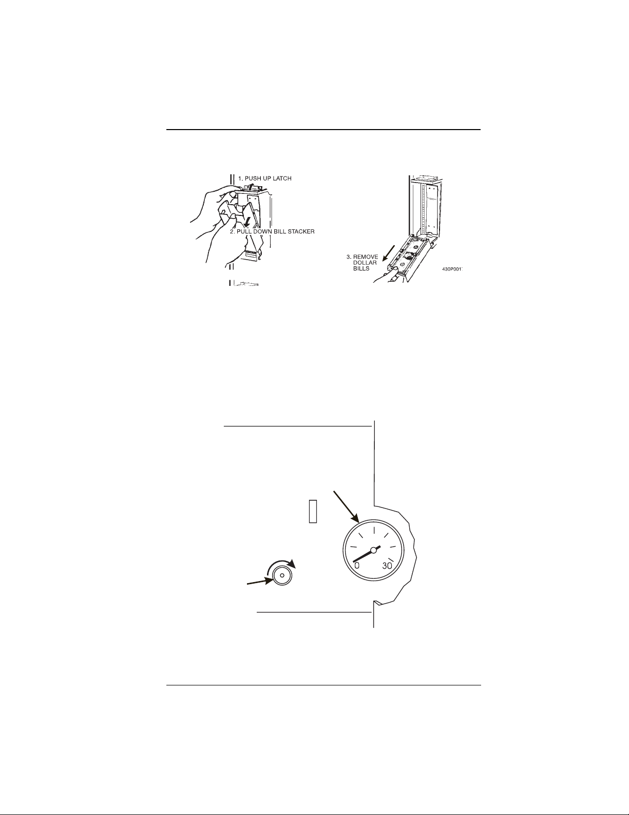
Emptying The Bi ll Stacke r...... .... ... .... .... ............... .... .... .... ............... .... .... ... .... ..... 11
Adjusting The Air Press ure C ont rol (Mo de l 63 9 Onl y). ....... ... .... .... .... ............... . 11
Cup Mechanism Adjustment .............................................................................. 12
Hot Water Valve Adju s tmen t...... ............... .... ... .... ................ ... .... .... ............... .... . 13
Cold Water Valve Adjustment............................................................................. 13
View A ................................................................................................................. 13
View B................................................................................................................. 13
Syrup Pump Adjus t ment............... .... .... .... .... ............... .... .... ... ................ ... .... .... . 14
Canister Installation ............................................................................................ 15
Programming .............................................................................................................. 16
How To Program Your Eurotwin......................................................................... 16
The Display s............... .... .... .... ............... .... .... ... ................ .... ... .... ............... .... .... . 17
The Function Ke ys . .... .... .... .... ............... .... .... ... ................ .... ... .... ............... .... .... . 17
Other Keys .......................................................................................................... 17
Control Panel Switch Functions Explained......................................................... 18
Programming Flowcharts.................................................................................... 19
Programming Procedures........................................................................................... 23
Gain Access To The Supervisor Mode ............................................................... 24
Enter A New Supervisor Code............................................................................ 24
Enter A New Freevend Code .............................................................................. 24
Lock Or Unlock Mode Or Payout Keys............................................................... 25
Set Printer Or Dex Options ................................................................................. 25
Lock Or Unlock Data Clearing Access ............................................................... 26
Assign A Code To View Data Without Opening The Door.................................. 26
Select Printer Baud Rate (Printer Mode Only) .................................................... 27
6390031 Page i July, 20 01
Page 4

EUROTWIN OPERATOR’S GUIDE
Select Bill Validator And Options........................................................................ 28
Select Card Reader And Options ....................................................................... 29
Select Coin Mechanism And Options................................................................. 30
Select Monetary Options.................................................................................... 31
Select Display Language .................................................................................... 32
Set Up Winner Mode .......................................................................................... 33
Set Up Mug Discount.......................................................................................... 34
Set Up Machine Configuration Options (Supervisor Mode Only) ....................... 34
Identify The Active Selections In The Merchandiser
(Supervisor Only)................................................................................................. 36
Set Up Cup Sizes................................................................................................ 36
Set Up A Hot Drink ............................................................................................. 38
Collecting Dry Product Gram Throws................................................................. 40
Collecting Hot Water Throws.............................................................................. 43
Set Up A Cold Drink............................................................................................ 45
Collecting Cold Water And Syrup Throws......................................................... 46
View Software Version ........................................................................................ 46
Set Hot And Cold Temperature .......................................................................... 47
Set The Automatic Brewer Rinse Time
(Brewer Equipped Machines Only) ..................................................................... 48
Set The Automatic Mixing Bowl Rinse Time....................................................... 49
Set The Time Of Day........................................................................................... 50
Set The Day Of The Week................................................................................... 50
Set Month, Day, And Year .................................................................................. 50
Set Time-of-day Inhibited Vending ..................................................................... 51
Set Time-of-day Free Vending............................................................................ 51
Set Time-of-day Discount Vending..................................................................... 51
Time Interval Editing ........................................................................................... 52
Select A Standby Message................................................................................. 54
Select An Out-of -ser vic e M ess ag e.......................... .... .... .... ............... .... ... .... ..... 54
Select A Freevend Message............................................................................... 55
Edit Custom Messages....................................................................................... 56
The End Of Message Character.......................................................................... 56
Entering Your Message....................................................................................... 57
View Water Tank And Cold Plate Temperature .................................................. 58
View Machine Configuration Setting................................................................... 58
Payout Coins....................................................................................................... 59
Set Prices............................................................................................................ 60
Set Entire Machine To One Price . . ................................................................... 60
Set The Price Of An Individual Selection . . . ...................................................... 60
Set All Cup Sizes To One Pri c e . . . .............. ... .... .... ............... .... .... .... .... ............ 60
Set All Sizes Of A Selection To One Price . . ..................................................... 61
View Nonresettable Sales And Vend Data.......................................................... 61
View Data Three Different Ways ......................................................................... 62
View Total Paid Sales ......................................................................................... 62
View Total Paid Vends........................................................................................ 62
Clear All Resettable Data.................................................................................... 63
Clear Paid Sales Data Only................................................................................. 63
View Amount In Coin Box (Not Shown If Zero)................................................... 63
View Amount In Validator (Not Shown If Zero).................................................... 64
View Freevend Sales By Time Interval (Not Shown If Zero)................................ 64
View Discount Sales By Time Interval................................................................. 64
6390031 Page ii July, 2001
Page 5

EUROTWIN OPERATOR’S GUIDE
View Free Vends (Not Shown If Zero)................................................................. 65
View Winners (Not Shown If Zero) ...................................................................... 65
View Time Data................................................................................................... 66
View Total Unpaid Sales..................................................................................... 67
View Total Unpaid Vends.................................................................................... 67
View Number Of Test Vends (Not Shown If Zero)............................................... 67
View Number Of Mug Vends (Not Shown If Zero) .............................................. 67
View Machine Id Number.................................................................................... 68
Test Vend Selections And Verify Credit Added.................................................. 68
Test The Display ................................................................................................. 68
Test Drop A Cup ................................................................................................. 69
Test The Whipper(s)............................................................................................ 69
Test The Air Compressor .................................................................................... 69
Test The Brewer.................................................................................................. 70
Rinse The Mixing Bowls...................................................................................... 70
Rinse The Brewer................................................................................................ 70
Purge The Carbonator ........................................................................................ 71
Clear Tank Errors And Fill The Tank ................................................................... 71
Test Switches Or Sensors .................................................................................. 71
View Diagnostic Messages................................................................................. 72
Download Da ta To A PDCD.............. .... .... .... ............... .... .... ... ................ ... .... .... . 74
Set Freevend Options ......................................................................................... 74
Cleaning And Sanitation ............................................................................................. 75
Basics ................................................................................................................. 75
Overall Clea ning.. ... .... .... ............... .... .... .... ............... .... .... .... ............... .... ... .... ..... 77
Preventive Maintenance Cleaning ...................................................................... 77
Cleaning Procedures .......................................................................................... 77
Sanitation Procedures ........................................................................................ 78
Appendix A. The Infrared Mug/cup Sensor ..............................................................A-1
Appendix B. Modify Canister To Vend 12 Oz. Cups.................................................B-1
Appendix C. Clean The Hot Water Tank.................................................................. C-1
Appendix D. The Free Vend Keyswitch Option.........................................................D-1
6390031 Page ii i July, 2001
Page 6

EUROTWIN OPERATOR’S GUIDE
NK
A
L
B
T
F
E
L
Y
L
L
NA
TIO
N
E
NT
I
IS
GE
A
P
S
HI
T
6390031 Page iv July, 20 01
Page 7

EUROTWIN OPERATOR’S GUIDE
INITIAL SET-UP
I. POWER REQUIREMENTS
This merchandiser requires power as shown in the following table. NOTE: Each merchandiser should have its own electrical circuit
Power Requirements
Country Volts Frequency (Hz) Current (Amps)
Canada 115 60 15
France 230 50 10
Germany 230 50 10
Unite d Kin g d om 230 50 10
United States 115 60 15
II. WATER REQUIREMENTS
The best type of water for coffee brewing is normal hard water. If your location has
chemically softened water, one of the following steps is advi sed:
• Have a non-softened su pply line run to the merchandiser
• Contact your loc al water filter supplier for informatio n and suggestions
Well wate r can also be used in the EuroTwin Machine. However, you should have it
checked for levels of carbonates and alkalies. Contact your water filter supplier if
these values are relatively high.
WA TER PRESSURE
• Minimum water pressure: 20 psi (138.0 KPa) at 1/2 gallon/minute
• Maximum water pressure: 80 psi (522.0 KPa) at 1/2 gallon/minute
SUPPLY LINE REQUIREMENTS
• Locate the supply line at the rear of the merchandiser.
• Equip the line with a shut-off valve.
FLUSHING THE WATER SUPPLY LINE
Flush the water supply line bef ore connecting it to t he merchandiser. A minimum of
five gallons is usually required before connecting the merchandiser to the supply line.
DO NOT flush the merchandiser water system to avoid introducing possible water line
contaminants into the merchandiser.
6390031 Page 1 July, 2001
Page 8

EUROTWIN OPERATOR ’S GUID E
III. POSITIONING THE MERCHANDISER
You can position this merchandiser anywhere in a bank of machines. It can even be
placed on the end flush against a side wall.
Leave enough room in front of the merchandiser for the door to move freely.
BE SURE THE REAR OF THE MERCHANDISER IS AT LEAST 6" AWAY FROM THE
WALL. THIS WILL ENSURE WARM MOIST AIR IS VENTED OUT OF THE
MACHINE’S INTERIOR AND THE REFRIGERATOR CONDENSER FAN IS NOT
OBSTRUCTED.
WARNING
THIS MACHINE IS ONLY RATED FOR INSTALLATI ON IN AN
INDOOR LOC ATION.
IV. FINAL I N S TALLATI O N
1. CONNECT THE MERCHANDISER TO THE WATER SUPPLY
a. You wil l need the following:
• A coil of copper tubin g with out side di ameter of 3/8 i nch (9.5 mm) o r greate r. The
appropriate plastic tubing may be substituted.
• A 3/8 inch (9.5 mm) flare fitting
b. Connect the merchandiser to your water supply.
2. CONNECT THE MERCHANDISER TO THE POWER SOURCE
Power to the merchandiser is controlled by the main power switch, located on the
power panel.
a. Make sure the main power switch is OFF.
b. Connect the merchandiserís power cord to your wall outlet.
July, 2001 Page 2 6390031
Page 9
EUROTWIN OPERATOR’S GUIDE
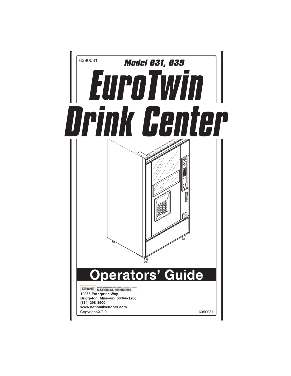
3. LEVEL THE MERCHANDISER
a. Place a spirit level on the top front edge of the cabinet with the door fully
closed. Adjust the fro nt legs only until the cabi net is reasonably lev el.
b. Hold the door open about 4 inches.
WARNING
HAVE AN ASSISTANT HOLD THE MERCHANDISER WHILE YOU
ADJUST THE LEG LEVELERS.
c. Adjust the back legs so that the back leg leveler on the hing e side is off the
floor just enough so a piece of paper can slide under it with only a bit of resi stance.
d. For proper weight distribution on all four legs, raise the back leg on the hinge
side by unscrewing the leveler 1¾ turns.
NOTE
You may need to use pliers or channel locks to loosen the leg levelers.
SPIRIT LEVEL
FRONT
LEG
LEFT REAR
LEG
LEG
LEVELER
1-1/2 TURNS
6390031 Page 3 July, 2001
Page 10
EUROTWIN OPERATOR ’S GUID E
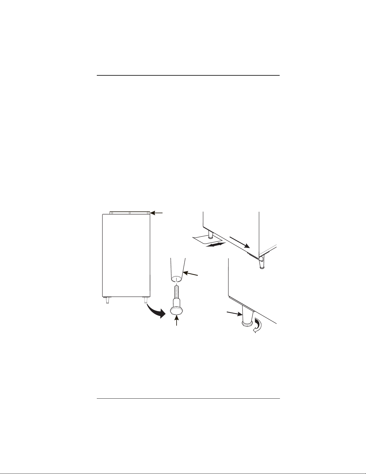
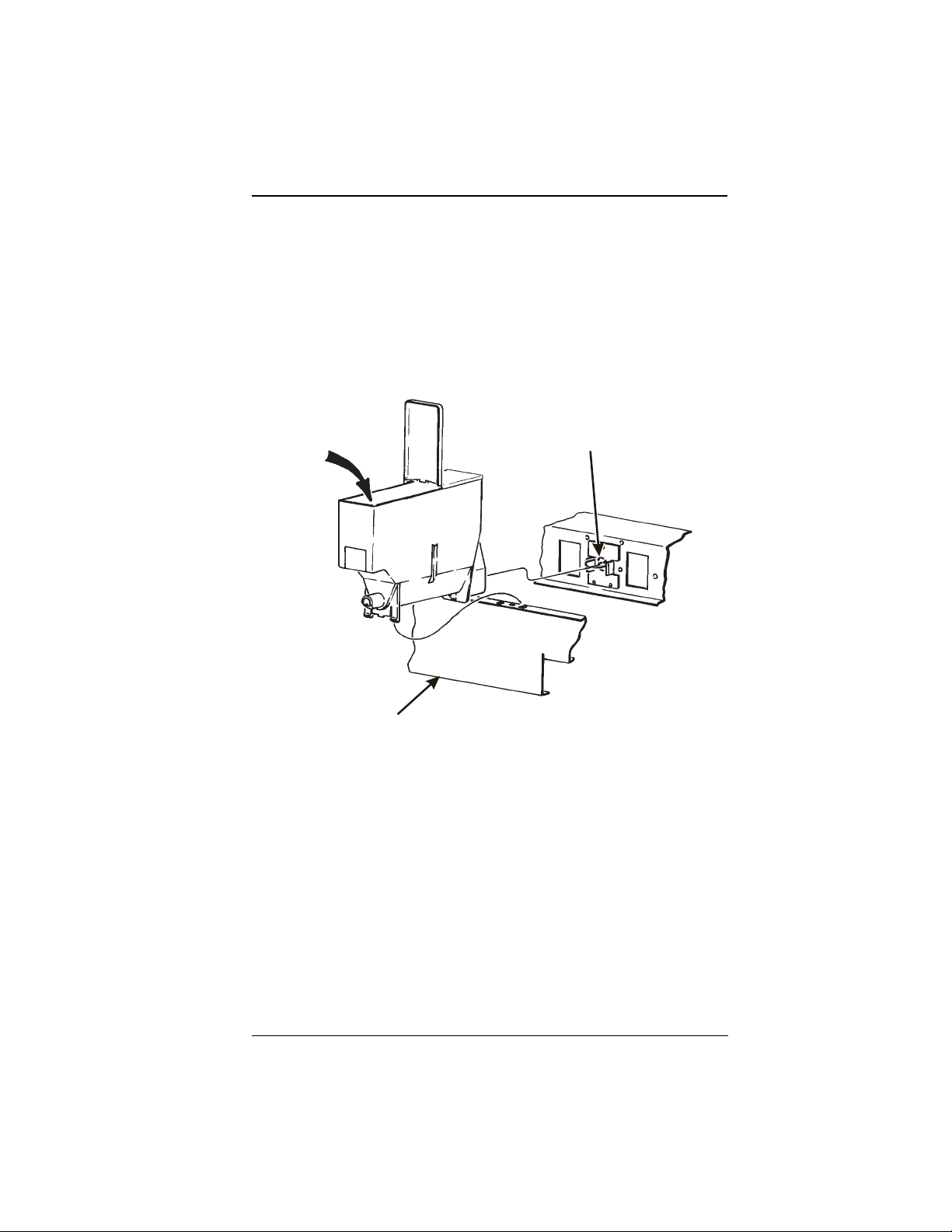
4. SET UP THE MENU ASSEMBLY
a. From the inside of the door, remove the two screws as indicat ed, and remove
the end cap as shown.
b. Loosen the rema ining 10 screws as indicat ed 1/2 turn. Do not loosen the
screws any more than necessary to avoid stripping out the menu frame.
c. Remove the menu board. If it is still held too tightly, repeat step 6.
d. Set up the menu board as desired and reinstall it in the reve rse order of disas-
sembly.
REMOVE THE MENU BOARD
END CAP AND SLIDE OUT THE
MENU BOARD.
LOOSEN
THESE
REMOVE
THESE
SCREWS
SCREWS
LOOSEN
THESE
SCREWS
July, 2001 Page 4 6390031
Page 11
EUROTWIN OPERATOR’S GUIDE
V. INSTALL OPTIONS
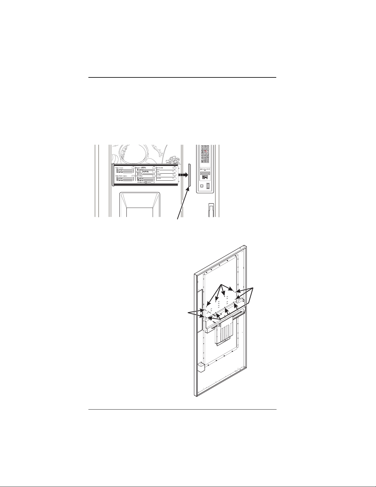
1. INSTALL THE COIN BOX LOCK
a. Install the lock cylinder, washer , and nut in the order shown.
b. Tighten the nut.
c. Install the lock bar as shown, and secu re with the screw.
LOCK BAR
NUT
LOCK
CYLINDER
2. MOUNT THE BASE PLATE BR ACKETS
WASHER
SCREW
a. Secure a base plate bracket at each of the remai ning pair s of holes wit h two of
the hex head screws.
6390031 Page 5 July, 2001
Page 12
EUROTWIN OPERATOR ’S GUID E
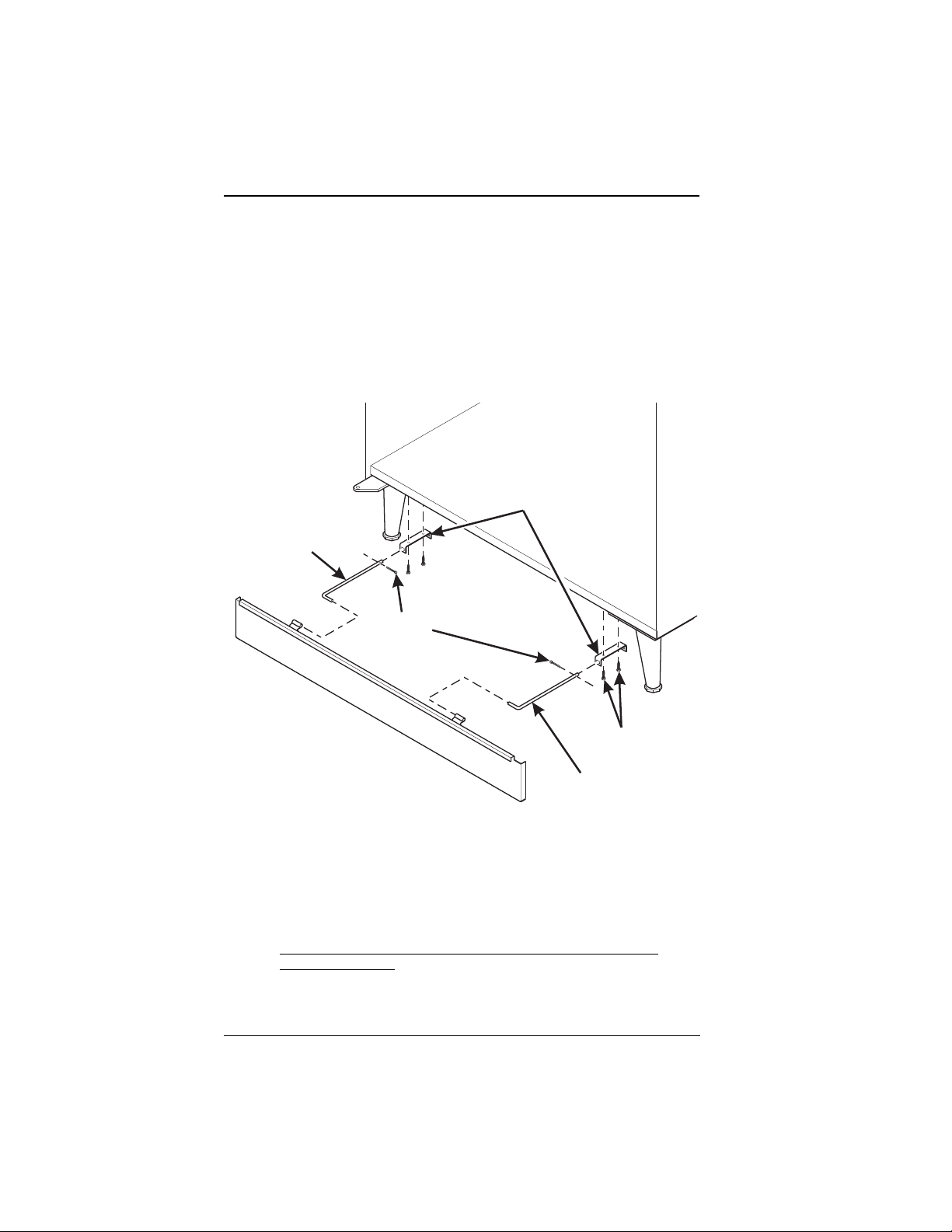
3. MOUNT THE BASE PLATE AND SLIDES
a. Insert the short arm of the slides into th e hinged tabs of the base plate. Posi-
tion the slide so the notch near the short arm is on the bottom side.
b. Insert the long arms of the slides into the base plate brackets.
c. Insert a cotter pin through th e hole in the back end of each slide. Secure the
pins in place.
d. Push the base plate towa rd the merchan diser cabinet. The front tab of the
base plate bracket should seat in the notch in the long arm of the slide.
BASE PLATE
MOUNTING
LEFT HAND
BASE PLATE
SLIDE
COTTER
PIN
BRACKET
HEX HEAD
SCREW
RIGHT HAND
BASE PLATE
SLIDE
CAUTION
The mounting brackets are subject to damage when moving the
machine with a fork lift.
Remove the brackets prior to moving the machine with a fork lift
to prevent damage.
July, 2001 Page 6 6390031
Page 13
EUROTWIN OPERATOR’S GUIDE
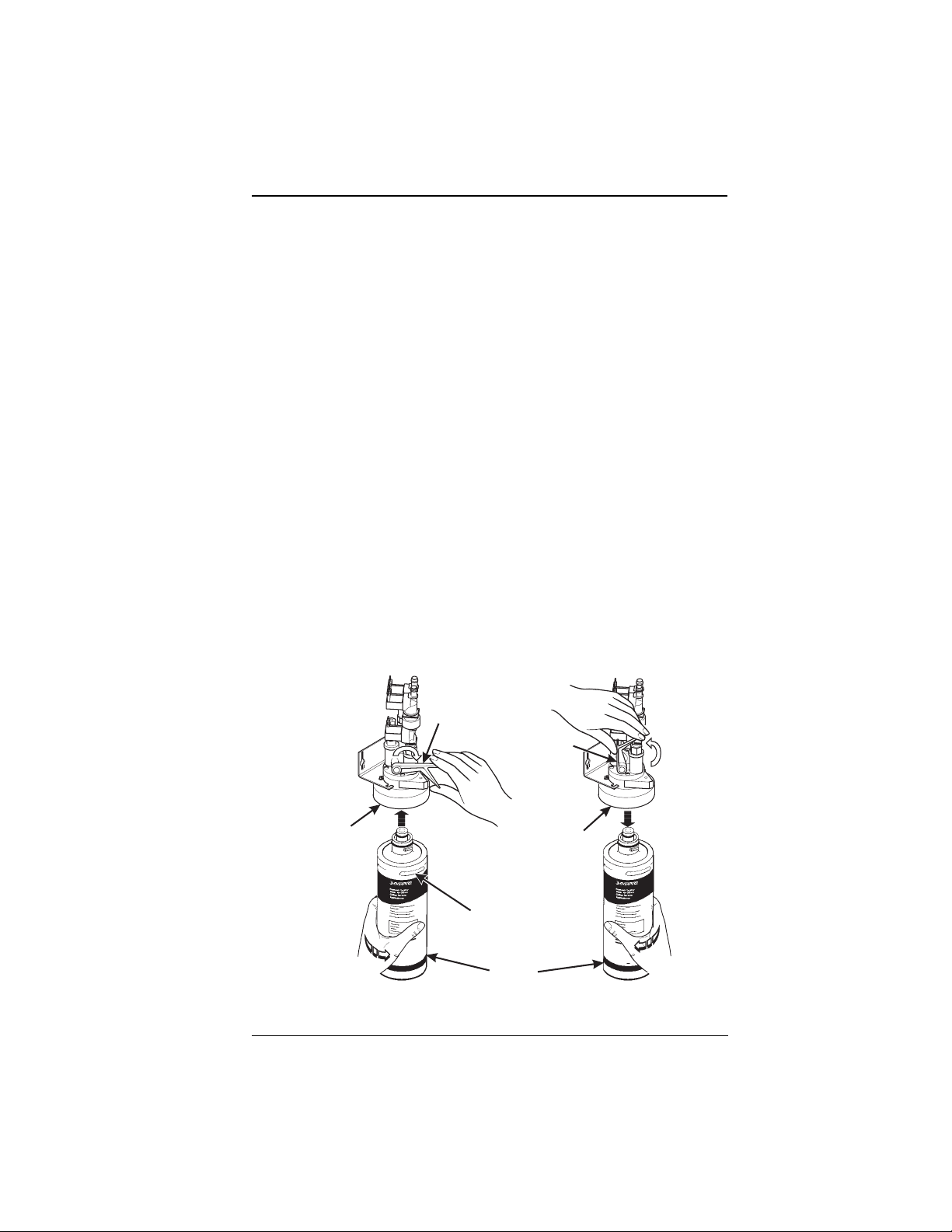
4. INSTALL THE WAT ER FILTER CARTRIDGE
IF YOUR M ERCHANDISER HAS THE WATER FILTER OPTION, IT
CANNOT BE OPERATED WITHOUT A PROPERLY INSTALLED
WATER FILTER CARTRIDGE.
NOTE
Check the water filter installation record. There is a place to write
the vend number on the cartridg e. The cartridge is effectiv e for a
maximum of 26,000 7 oz. vends, 22,000 8 oz. vends, 20,000 9 oz.
vends, or 15,000 12 oz. vends. Local conditions may require more
frequent replacement.
a. Yo ur filter cartridge is shi pped inside the waste pail. Locate it and remove the
wrapping.
b. Remove the liquid waste pail (if pr esent) to gain access to the wat er filter head
assembly, located at the right rear of the machine.
c. Install the filter as shown.
TO INSTALL FILTER:
1. ALIGN RAISED RIB ON
FILTER CARTRIDGE WITH
MATING SLOT IN HEAD
ASSEMBLY.
2. FIRMLY INSERT FILTER
CARTRIDGE INTO HEAD
ASSEMBLY AND ROTATE
COUNTER-CLOCKWISE
1/4 TURN TO THE STOP.
3. OPEN THE WATER SHUT-OFF
VALVE BY PUSHING THE
HANDLE TO THE HORIZONTICAL
POSITION AS SHOWN BELOW.
TO REMOVE FILTER:
1. CLOSE THE WA TER SHUT-OFF
VALVE BY LIFTING THE HANDLE
TO THE VERTICAL POSITION AS
SHOWN BELOW.
2. ROTATE THE FILTER
CLOCKWISE AND PULL
DOWN AS SHOWN.
WATER SHUT-OFF
VALVE HANDLE
WATER SHUT-OFF
VALVE HANDLE
RIB
EVERPURE
FILTER
CARTRIDGE
EVERPURE
FILTER HEAD
ASSEMBLY
4
H
EVERPURE
FILTER HEAD
ASSEMBLY
RAISED
4
H
6390031 Page 7 July, 2001
Page 14

EUROTWIN OPERATOR ’S GUID E
VI. GET THE MACHINE READY TO VEND DRINKS
1. SET UP TH E CO2 TANK
a. Place the power switch in the OFF position.
b. Inst all a full CO
c. Remove the CO
d. Locate the CO
plastic washer (in plastic bag).
e. Insert the tapered washer into the fl ar e nut of the CO
unit.
f. Using two wrenches, tighten the line to the regulator.
g. Insert the flat washer into the regulator nut.
h. Using two wrenches, connect the regulator to the tank outlet and tig hten in
place.
Not using a wrench on the tank side may damage the CO2 tank,
resulting in personal injury.
tank on the floor area in front of the cooling unit.
2
tank lid.
2
regulator and flat plastic washer (in a box), and the tapered
2
line connected to the
2
WARNING:
i. Open CO
j. Adjust the CO
k. Lock the adjustment screw in place.
l. Remove the cooling machine cover and actuate the pressure relief valve
located on top of the carbonator tank for 3 to 5 seconds.
m. Check for gas leaks along the CO
2. FILL THE HOT WATER TANK
If you hav e th e wa ter fil ter op ti on an d HAVE NOT yet instal led th e wa ter f il ter, retu rn to
step 7 and install the filter as instructed.
a. Turn on the water at its source.
b. Check for any water leaks.
c. Turn the machine po wer switch ON. The carbonator pump will start automati-
cally and will fill the car bonator with water.
d. Press .
e. Press until the display shows
f. Press again and let water flow into the tank.
g. The display will show
show
tank valve.
2
regulator so that the secondary gauge reads 5.50 bar (80 PSI).
2
TANK.FILL.
line.
2
TANK. FILL.
FILLING TANK. After the tank is filled the display will
July, 2001 Page 8 6390031
Page 15
EUROTWIN OPERATOR’S GUIDE
NOTE
The tank will take some time to fill and reach its operating temperature.
h. If this is the first time that the tank is being filled, perform the tank cleaning pro-
cedure given in Appendix C.
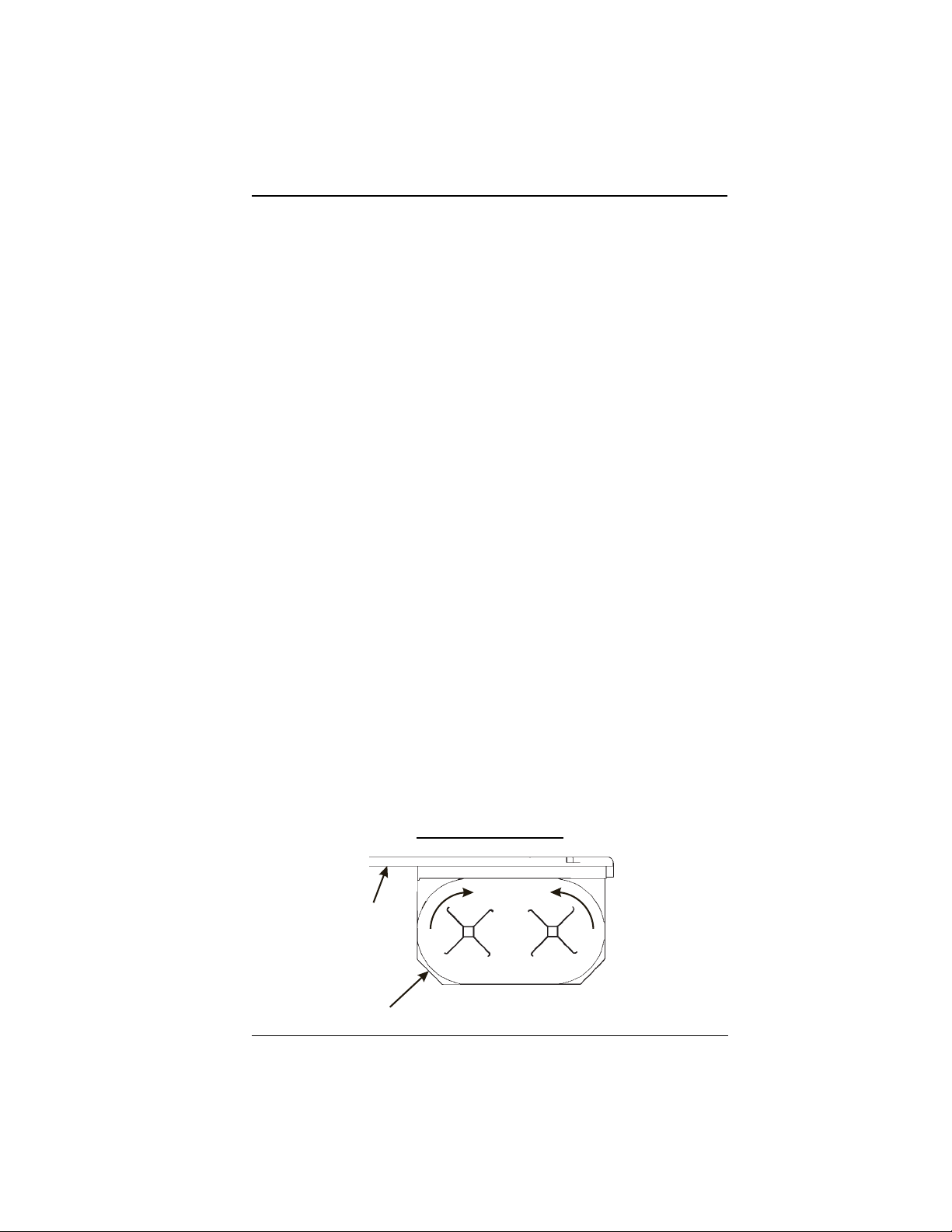
3. LOAD THE CUP MECHANISM
CAUTION
Use only cups which have be en designed for use in a hot beverage
vending machine.
The size of cup you load must agree with the cup size that you will select during programming.
a. Support the cup mechanism in the upright position.
b. Push the la tch forw ard to r elease the cu p mechan ism. Contin ue to su pport the
cup mechanism while you lower it into the loading positi on.
c. Remove the turret cover.
OBSERVE PROPER HYGIENE - DO NOT TOUCH THE CUPS!
d. Open the bottom of the wrapper on a stack of cups.
e. Insert the wrapped cups into the turret and pull the wrapper out.
DO NOT FILL CUPS ABOVE THE LEVEL MARKED ON THE OUT-
SIDE OF TH E CU P TURRETS OR AB O V E TH E “F I LL LINE”
LABEL INSIDE EACH TURR ET, OR MOTOR JAMS WILL OCCUR.
USE ONLY THE SAME SIZE AND BRAND OF HOT DRINK CUPS
IN EACH TURRET; DO NOT INTERMIX!
f. Replace the turret cover after the turrets have been loaded.
g. Be sure the cup mechanism is locked into the upright position.
TURRET DESIGNATIONS
CUP STACK ROTATION
DOOR
1B 1A
CUP
MECHANISM
TOP VIEW
6390031 Page 9 July, 2001
Page 16
EUROTWIN OPERATOR ’S GUID E
CABINET
DOOR
RETAINING
STRAP
CUP MECH
MOUNTING
BRACKET
LID
LOAD CUPS
HERE
CUP TURRET
LATCH
CUPS
TOP VIEW
4. LOAD AND SET UP HOT DRINK PRODUCTS
a. Fill each canister with its res pective product .
b. Once the hot water tank has reached its operating temperature, perform test
vends (see COLL ECTING DRY PRODUCT GRAM THROWS and CO LLECT-
ING HOT WA TER THROWS). Adjustments may be necessary to water, prod-
uct, or condiment throw times, or to the hot water valves. Refer to the
appropriate sections in this manual for instructions on how to do this.
July, 2001 Page 10 6390031
Page 17
EUROTWIN OPERATOR’S GUIDE
ADJUSTMENTS AND MINOR MAINTENANCE
EMPTYING THE BILL STACKER
ADJUSTING THE AIR PRESSURE CONTROL (MODEL 639 ONLY).
This control determines the system pressure prov ided by the air compressor. Adjust
the pressure as follows:
a. With the compressor running, pinch the brewer inlet air tube.
b. Adjust the pressure to read 1 0 - 12 psi on the gauge.
This will produce a pressu re of 3 - 6 psi using regul ar coffee and 8º oz cups . No further air pressure adjustments should be necessar y.
PRESSURE
ADJUST
CONTROL
PRESSURE
GAUGE (AIR)
INCREASE
INGREDIENTS SHELF
MONETARY
PANEL
AIR PRESSURE CONTROLS
6390031 Page 11 July, 2001
Page 18
EUROTWIN OPERATOR ’S GUID E
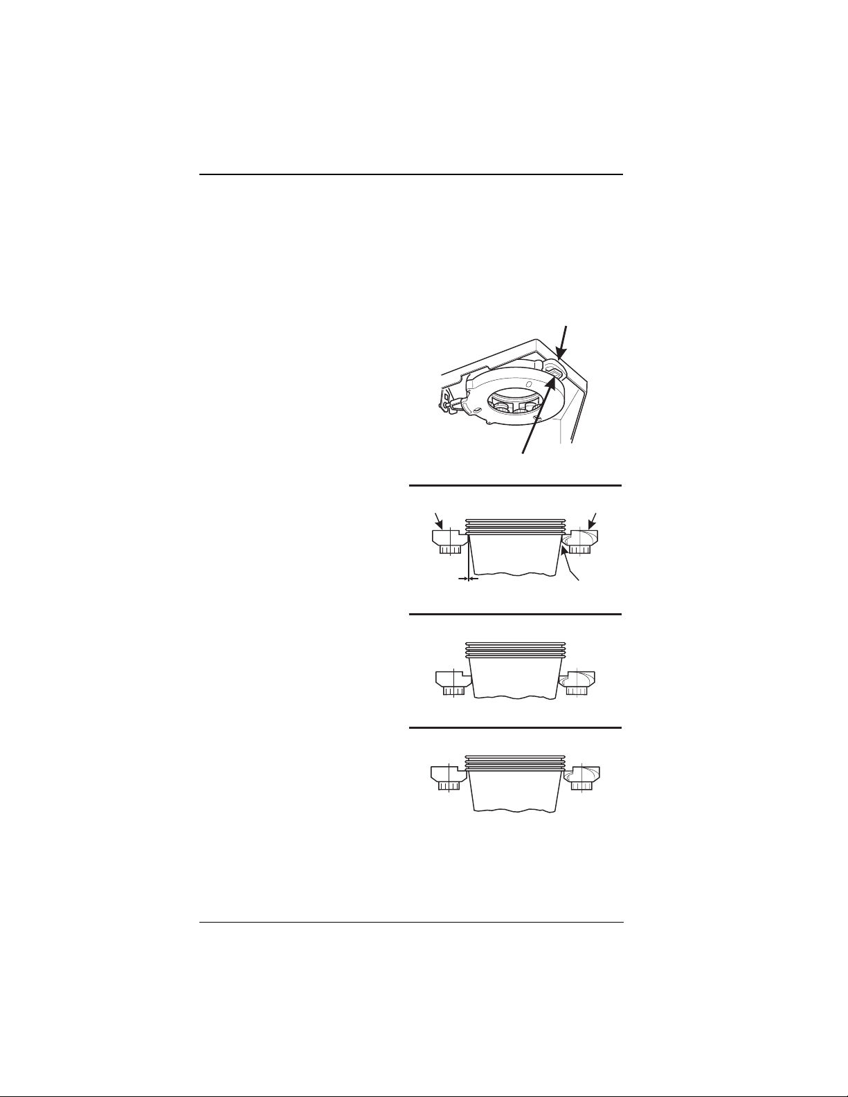
CUP MECHANISM ADJUSTMENT
1. Pl ac e se v en cu p s in the cup ring.
2. Observe the clearance as shown in view B.
3. If necessary adjust by f irst loosening the adjust men t ar m screw (view A).
4. Move adjustment arm until correct clearance is achieved.
5. Hold adjustment arm in place and tighten adjustment arm screw.
ADJUSTMENT
ARM
VIEW A
LOOSEN SCREW
MOVE ARM
CUP
CAM
CORRECT
VIEW B
This clearance is just
large enough to allow
ADJUSTMENT
cup ejection
This side is snug
against cam
CUP
CAM
ADJUSTED
TOO TIGHT
ADJUSTED
TOO LOOSE
316P0118
July, 2001 Page 12 6390031
Page 19
EUROTWIN OPERATOR’S GUIDE
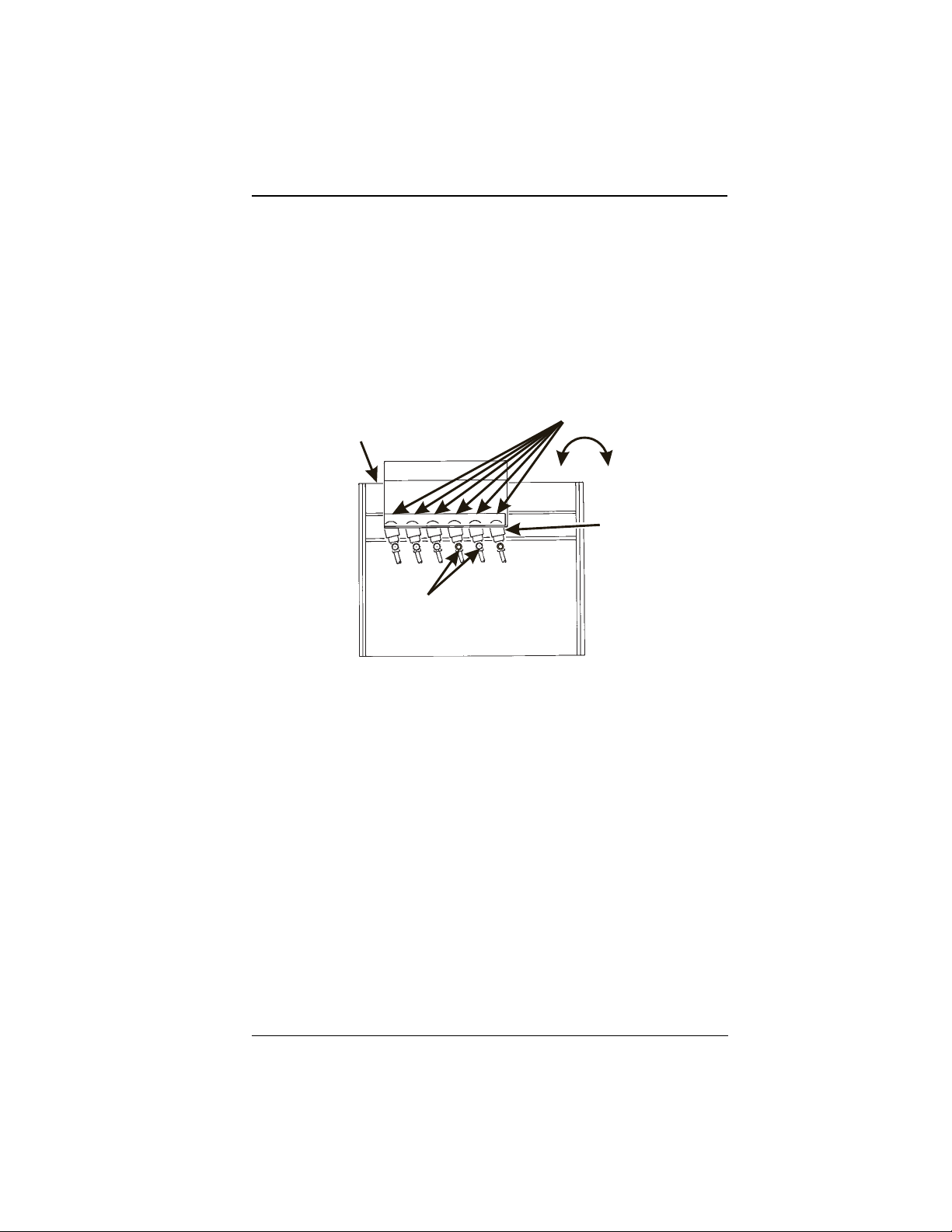
HOT WATER VALVE ADJUSTMENT
The hot water valves do not u sually require adjustment, but in some cas es adequate
water volume cannot be achieved by the throw time setting alone (see the programming section). IF ABSOLUTELY NECESSAR Y, adjust the valves in conjunction with
setting the fac tory default timers.
1. Using a slotted scr ewdriver, turn the adjustment screw cl ockwise t o decre ase the
water flow rate.
2. Turn the adjustment screw counterclockwise to increase the water flow rate.
WATER
TANK
WATER VALVE
ADJUSTMENT
SCREW
123456
WATER
+
6
-
WATER
VALVE
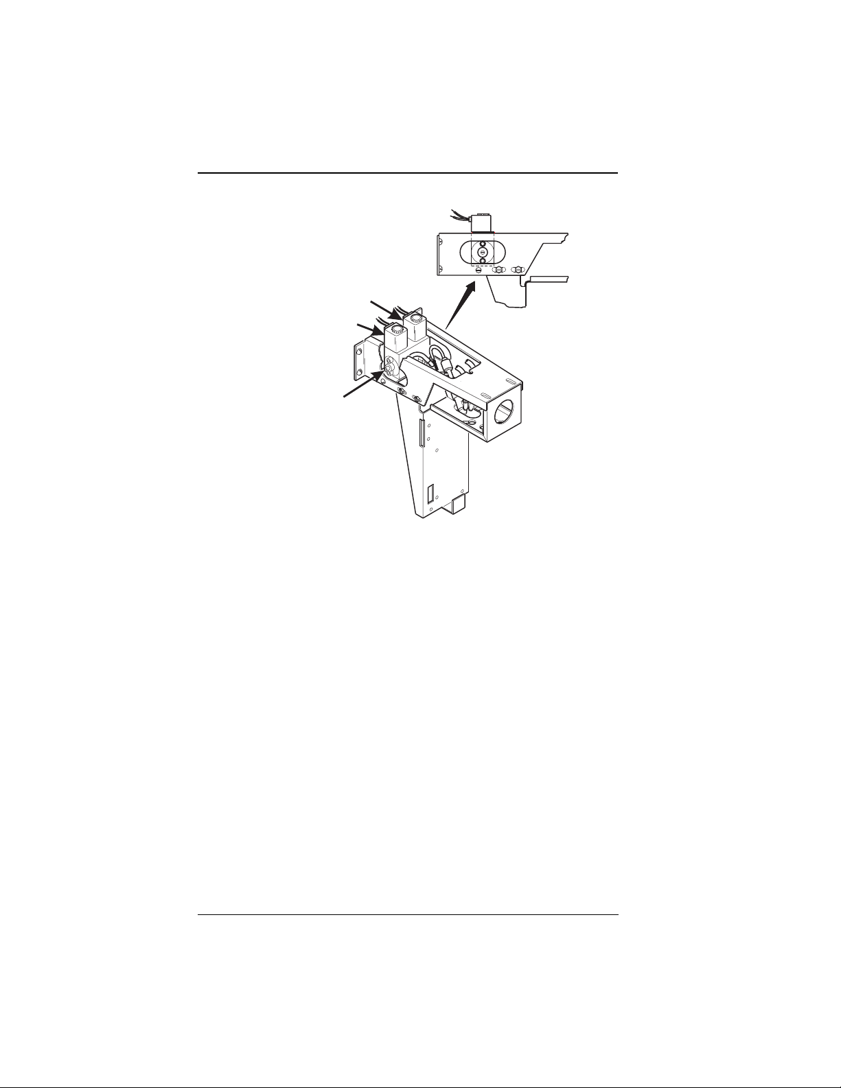
COLD WATER VALVE ADJUSTME NT
Cold water valves do not us ually require adjustment, but in cert ain cases adequate
water volume cannot be achieved by adjusting the throw time setting alone (see the
programming section). IF ABSOLUTELY NECESSARY, ADJUST THE VALVES IN
CONJUNCTION WITH SETTING THE TIMERS.
1. Turn the carbonated water adjustment screw counterclockwise (CCW) until it
stops in the fully open position. Do not force it to stop the flow because it is not
a positive closure system.
2. Turn it clockwise (CW) 3 full turns.
3. Turn the non-carbonated water adjustment screw CCW until it stops. Do not
force it to stop the flow because it is not a positive closur e system.
4. Turn it back clockwise (CW) 1 full turn.
6390031 Page 13 July, 2001
Page 20
EUROTWIN OPERATOR ’S GUID E
CARBONATED
WATER VALVE
NON-CARBONATED
WATER VALVE
ADJUSTMENT
SCREW
SYRUP PUMP ADJUSTMENT
The syrup pumps do not usually require a d justment, but in some cases adeq ua te volume cannot be achieved by the thro w time setting alone (see the prog ramming section). IF ABSOLUTELY NECESSARY, ADJUST THE VALVES IN CONJUNCTION WITH
SETTING THE FACTORY DEFAULT TIMERS.
1. Loosen the locknut on the syrup pump adjustment screw.
2. T urn the screw clockwise (CW) until it is flush with the upper face of the locknut.
3. T urn the screw counterclockwise (CCW) 3 full turns.
4. Tighten the locknut to secure the screw.
5. Repeat steps 1 through 4 for the other syrup valve.
July, 2001 Page 14 6390031
Page 21
EUROTWIN OPERATOR’S GUIDE
CANISTER INSTALLATION
1. Place the canister in position as shown.
2. Engage the pins on the motor shaft with the slo ts in the canister coupler.
3. Fit tabs on caniste r into t he slots on the canister shelf.
4. To ensure canister is correctly engaged with the rear moun ting bracket, gently
push down on the front edge of the canister lid.
PINS ON MOTOR
PINS ON MOTOR
SHAFT MUST ENGAGE
SHAFT MUST ENGAGE
SLOTS IN CANISTER
SLOTS
IN CANISTER
COUPLER
FILL
FILL
CANISTER
CANISTER
COUPLER
626P0017
CANISTER
CANISTER
SHELF
SHELF
6390031 Page 15 July, 2001
Page 22
EUROTWIN OPERATOR ’S GUID E
PROGRAMMING
HOW TO PROGRAM YOUR EUROTWIN
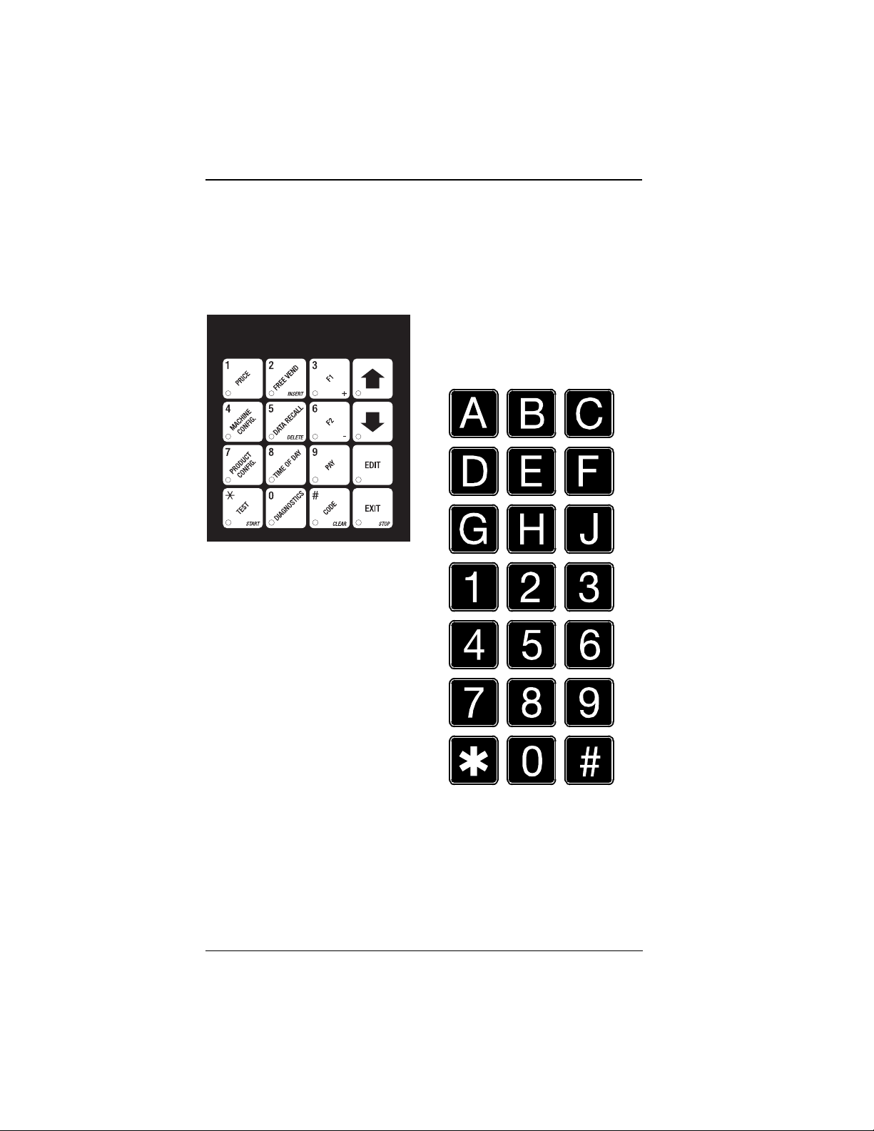
Some setup, test, and maintenance operations are computer controlled. The control
panel switches (see fi gure 1) and the selection panel switches (see figure 2) regulate
these oper a tio ns .
Figure 1. Contro l Pane l
157p0 248
Figure 2. Selec ti on Pa ne l
July, 2001 Page 16 6390031
Page 23
EUROTWIN OPERATOR’S GUIDE
THE DISPLAYS
The 10-character display performs two functions, and is referred to in this book as
"the display":
1. It shows the customer’s selection and how much credit is in the machine, as well
as the ready, service, and time of day messages.
2. It provides infor mation and feedback to the servi ce person during mainten ance.
X
I
8
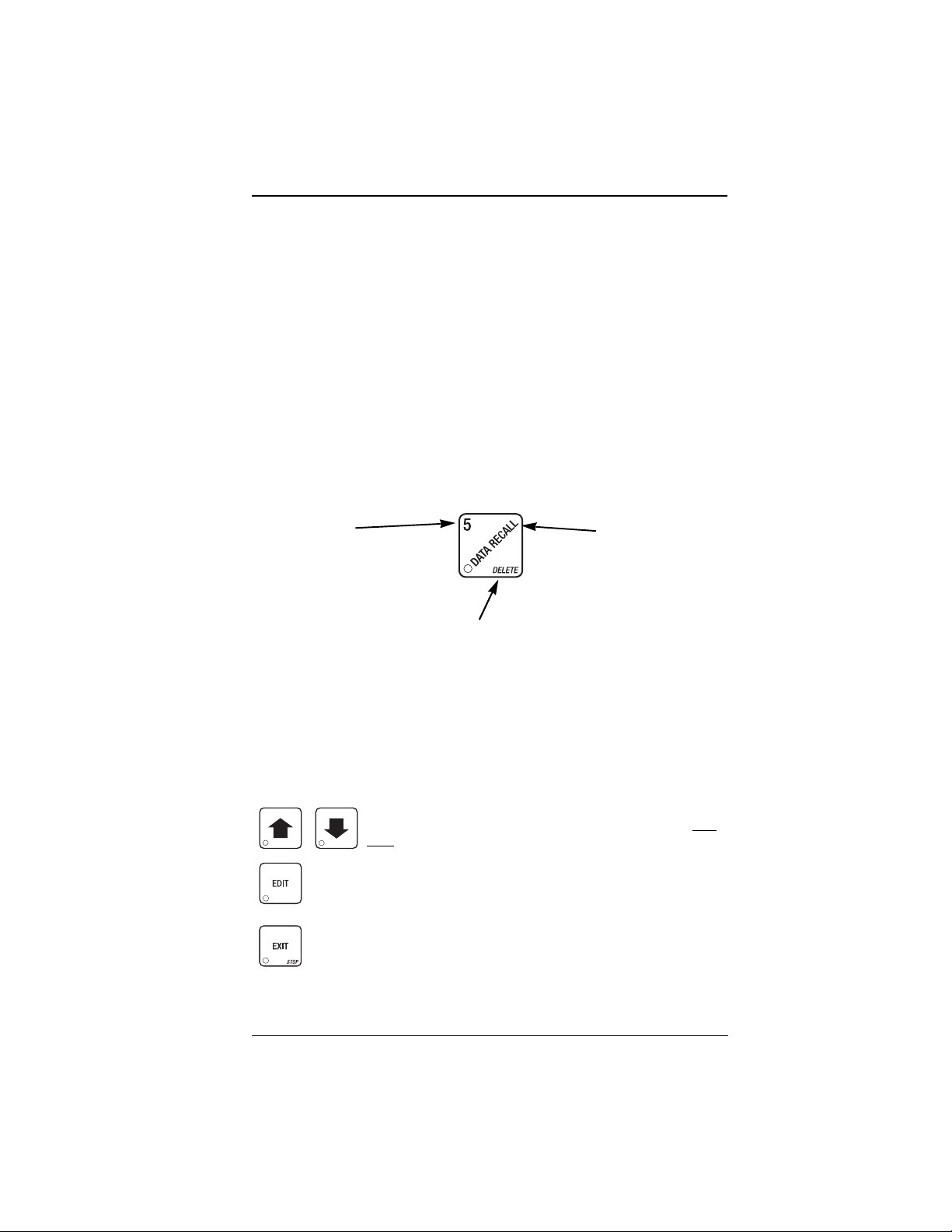
THE FUNCTION KEYS
The keys on the control panel can be used for up to three things:
THE NUMBER
YOU MIGHT BE ASKED TO ENTER A
NUMERICAL
THIS
OTHER KEYS
The MOVEMENT keys on the co ntrol pane l let you mov e inside a m ode, and b ack and
forth between modes. To see how these keys let you move aro und, stud y the flow
diagram on the next page.
VALUE
.
KEY WILL ENTER A
This is your "activate" or "choose" key. It "opens a door" to additional information and let s you begin a programming task once you are inside of a
mode. Sometimes, it is used as a toggle swi tch to show you your ch oices
during a programming task.
This is your "end" key. Pressing it one or more times will move you back to
the start of the mode, or all the way back to the standby message.
PRESSING
"5".
THE SECONDARY PURPOSE
THIS IS THE KEY’S "SECOND JOB
FOR EXAMPLE, THIS KEY CAN BE USED
DELETE A CHARACTER WHEN YOU
TO
ARE
EDITING CUSTOM MESSAGES
The up and down arrow ke ys are your "leg s" , which let you move
up and down the list of tasks. These keys are what let you continue from one step to the next in prog ramming procedures.
THIS IS THE MAIN JOB OF THE KEY
THE
YOU
IN THIS EXAMPLE, YOU CAN VIEW STORED
SALES
".
.
THE PRIMARY PURPOSE
.
STANDBY MESSAGE, IT WILL ALLOW
TO
ENTER A PROGRAMMING MODE
DATA
.
FROM
.
6390031 Page 17 July, 2001
Page 24

EUROTWIN OPERATOR ’S GUID E
CONTROL PANEL SWITCH FUNCTIONS EXPLAINED
Each of the control panel switches has one or more jobs to do. This lis t will give you a
short overview of those jobs..
Press this button to put your machine into the Price Setting mode. You
can see maximum and minimum machin e pr ices, and change prices for
entire machine or in dividual selection.
Press this button to set up how the Free Vend mode will operat e.
Press this button to view the water tank and cold plate temperatures, software version number, machine configuratio n, and active selection stat us.
Press this button to:
• Select display language
• Select coin mechanism and
options
Press this button to view total sales and vends by whole machine, selection, or drink size. Clear resettable data.
Press this button to:
• Download data into your portable data collection device (PDCD), OR
• Set printer baud rate, depending upon which device you are using
Press this butto n to:
• Set machine configuration
• Set up drinks
• Set which selections are act ive
Press this button to:
• Set time of day
• Set day, month, year
• Set up tim e of day intervals for
inhibit, freevend, and discount
vending
Press this button to pay one or more coins from the coin mechanism.
• Select bill validator and o ptions
• Set winner feature
• Set cup size
• Select sanitation and rinse times
• Set ta nk temper ature
• Select display messag e s
• Edit messages
Allow s yo u to se e an y fau lt or condition that has place d the mac h ine out of
service
Press this butto n to:
• Perform TEST VENDS
• Test machine functions
Press this butto n to:
• Enter the SUPERVISOR mode
• Change the SUPERVISOR access code
• Lock and unlock access to functions
July, 2001 Page 18 6390031
• Tes t display s
• Fill the water tank
Page 25

EUROTWIN OPERATOR’S GUIDE
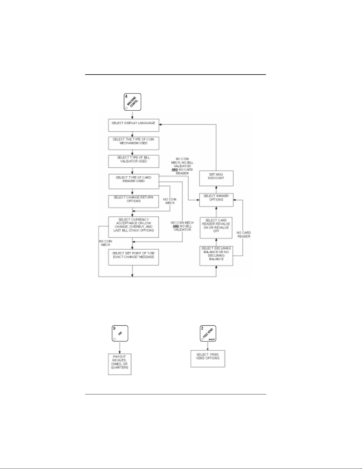
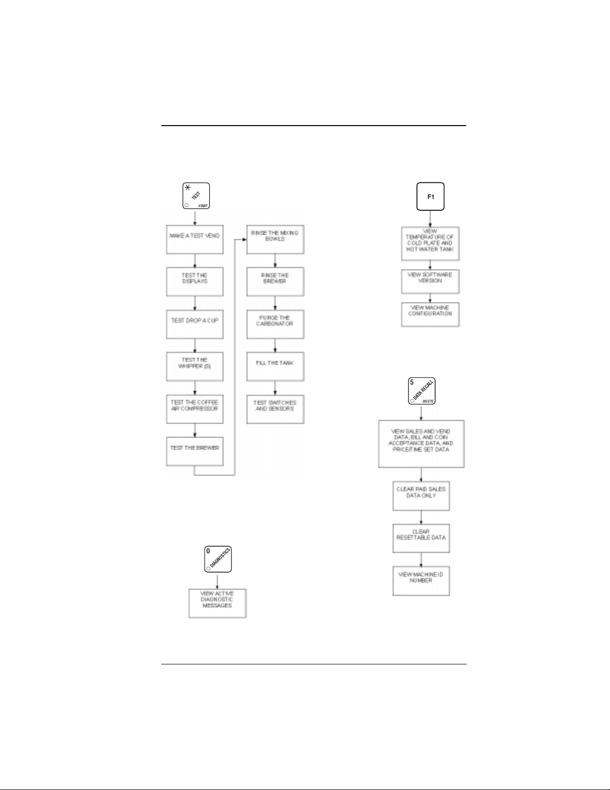
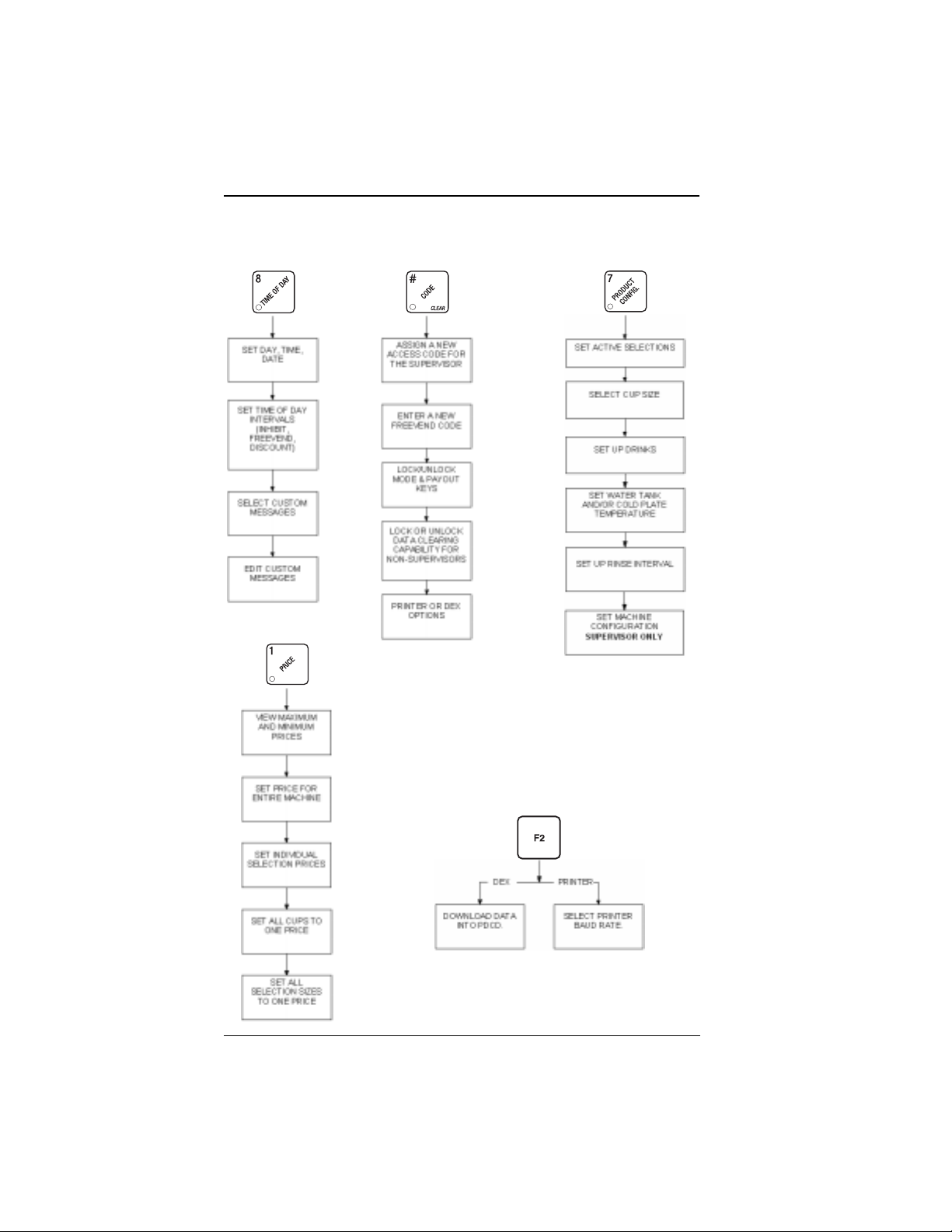
PROGRAMMING FLOWCHARTS
The flowcharts on the following pages will provide you with a "map" to the different
programming features of your machi ne. Once yo u are familiar with the detailed programming steps given later in this section, you can use the flowcharts as a shortcut.
Each chart begins with the key you will use to access those st eps. Follow the lines
and arrows fr o m one step to another. A rectangular box contains the functions or
tasks you will perf orm at that point. Sometimes, you have to make a deci sion. For
example, look at the MACHINE CONFIGURATION chart. At one point, you are asked
to select your monetary options (coin mech, bill validator, etc.). Depending upon your
choice, you wi ll take a different pat h. Note that if you have no mech, no validator, and
no card reader, you bypass a whole lot of other options and are tak e n right to the winner selection screen. Just follow the lines and arrows, and you will get through it.
6390031 Page 19 July, 2001
Page 26
EUROTWIN OPERATOR ’S GUID E
Payout Coins
PAGE 59
Machine Configuration
PAGE 32
PAGE 30
PAG E 28
PAGE 29
PAGE 30
PAGE 31
PAGE 30
PAGE 30
PAGE 30
PAGE 29
PAGE 31
Free Vend
PAGE 74
July, 2001 Page 20 6390031
Page 27
EUROTWIN OPERATOR’S GUIDE
Tests Misc.
PAGE 68
PAGE 68
PAGE 69
PAGE 69
PAGE 69
PAGE 70
View
Diagnostics
PAGE 70
PAGE 70
PAGE 71
PAGE 71
PAGE 71
PAGE 58
PAG E 46
PAGE 58
View and/or
Clear Data
PAGE 61 THRU PAGE 67
PAGE 63
PAGE 63
PAGE 68
PAGE 72
6390031 Page 21 July, 2001
Page 28
EUROTWIN OPERATOR ’S GUID E
Time of Day Supervisor Functions Product Configuration
PAGE 50
PAGE 51
PAGE 55
PAG E 56
Pricing
PAGE 60
PAGE 60
PAGE 24
PAGE 24
PAGE 25
PAGE 26
PAGE 25
PAGE 36
PAGE 36
PAGE 38
PAGE 47
PAGE 48
PAG E 34
DEX/Printer
PAG E 60
PAGE 60
PAGE 60
PAGE 74
PAGE 27
July, 2001 Page 22 6390031
Page 29

EUROTWIN OPERATOR’S GUIDE
PROGRAMMING PROCEDURES
The pages that follow contain all the programming steps you will need for the EuroTwin merchandiser. Each procedure is presented so that it "stands alone". This means
that you can look up a procedure , go dir ectly to it, perform the pr ocedur e, quit the pr ocedure then go on about your business.
However, after looking at the pro g ramming flowcharts, you should notice that several
procedures are grouped under each mode key (such as ), and you can move
between them by u sing t he up and do wn a rrow keys. Th erefore, you don’t have to exit
a procedure befo re performing another one.
Most procedures respond to you t he same way, li ke how to enter, leave, and move
around inside them. Her e is a short guide to help you thro ugh t hese common steps:
• To move directly from one procedure to another (pro vided they are both grouped
under the same mode key), use and .
• When you are finished with a function, you will want to CONTINUE. To do that,
you can press (you may have to press it more than once, depending on
how far into a p rocedu re you ar e). You can then perf orm anoth er prog ramming o r
maintenance f unction. If you are completely done with maintenance, just shut
the merchandiser door.
• Text that looks like this:
the monetary panel.
• Definitions and helpful information will appear in shadow boxes:
6390031 Page 23 July, 2001
DISPLAY represents what you will see in the display on
Page 30

EUROTWIN OPERATOR ’S GUID E
GAIN ACCESS TO THE SUPERVISOR MODE
1. Press . The displ ay sh ow s: ENTER CODE. You must enter the four-digit
supervisor code within 6 seconds to gain access.
NOTE
A new machine has a factory-set super visor code of 0000.
When you have entered the right code, you will hear two beeps and see
UNLOCKED in th e di s pl a y. After a few m om e n ts , th e
standby message returns.
2. At the standby message , press , then . You are now ready to
perform various supervisor functions.
ENTER A NEW SUPERVISOR CODE
1. If you a lr ead y ent er e d you r sup er viso r co de, skip to st ep 3. If n ot, foll ow th e ste ps
in GAIN ACCESS TO SUPERVISOR MODE, then return here.
IMPORTANT
If you enter a new code, be sure t o keep a written record of it. Ther e
is no other way to access the SUPERVISOR mode.
3. Press until the di splay sho ws
rent superviso r code. Use the number keys to enter a new code.
2. CONTINUE.
SUPER XXXX. The X’s r epresent the cur-
ENTER A NEW FREEVEND CODE
1. If you a lr ead y ent er e d you r sup er viso r co de, skip to st ep 4. If n ot, foll ow th e ste ps
in GAIN ACCESS TO SUPERVISOR MODE, then return here.
4. Press until the display shows
rent freevend code. U s e the nu mber keys to enter a new code.
See Appendix D for more inform ation on the freevend keyswi tch.
2. CONTINUE.
July, 2001 Page 24 6390031
FREE XXXX. The X’s represent the cur-
NOTE
Page 31

EUROTWIN OPERATOR’S GUIDE
LOCK OR UNLOCK MODE OR PAYOUT KEYS
1. If you a lr ead y ent er e d you r sup er viso r co de, skip to st ep 1. If n ot, foll ow th e ste ps
in GAIN ACCESS TO SUPERVISOR MODE, then return here.
1. Pre ss until the d isp la y show s eit her
refers to the number or character shown on the mode or payou t key in question
(1 through 9, # and *). To see if a key is locked or unlocked, press that key.
2. Press to change between locked and unlocked. When anyone other
than the supervisor t ries to enter a locked mode, the display shows
NOTE
The following mode keys cannot be locked out:
2. CONTINUE.
X. LOCKED or X. UNLOCKED. "X"
LOCKED.
SET PRI N TE R OR DEX OPTIONS
1. If you a lr ead y ent er e d you r sup er viso r co de, skip to st ep 3. If n ot, foll ow th e ste ps
in GAIN ACCESS TO SUPERVISOR MODE, then return here.
3. Press until the dis p la y shows one of the foll o wing:
PRINTER means that data will be se nt di rectly to a printer,
OR
DEX ONLY means that data remains i n me mory after it is downloaded into a por-
table data collection devi ce,
OR
DEX +C LR means that reset table data is cleared after it is downloaded into a por-
table data collection devi ce.
4. Press to switch between the three choices.
2. CONTINUE.
6390031 Page 25 July, 2001
Page 32

EUROTWIN OPERATOR ’S GUID E
LOCK OR UNLOCK DATA CLEARING ACCESS
1. If you a lr ead y ent er e d you r sup er viso r co de, skip to st ep 2. If n ot, foll ow th e ste ps
in GAIN ACCESS TO SUPERVISOR MODE, then return here.
1. Press until the displ ay shows either
LOCKED means that non-supervisors cannot clea r reset table machi ne sale s and
vend d ata from the key.
2. Press to switch between
#. LOCKED and #. UNLOCKED.
#. LOCKED or #. UNLOCKED.
NOTE
The supervisor can cl ear da ta r egard less of th is set ting, pr o vided t he
supervisor code was cor rectly entered first.
2. CONTINUE.
ASSIGN A CODE TO VIEW DATA WITHOUT OPENING
THE DOOR
If the prop er code is entered, s a les and vend data can be viewed without opening the
machine’s door.
1. Follow the steps in GAIN ACCESS TO THE SUPERVISOR MODE.
2. Press until the displ ay shows
rently entered code. Use the number keys to enter a new code, if desired.
NR XXXX. The X's repr esent the cur-
3. CONTINUE.
July, 2001 Page 26 6390031
Page 33

EUROTWIN OPERATOR’S GUIDE
SELECT PRINTER BAUD RATE (PRINTER MODE
ONLY)
BAUD
RATE
1. Press . One of the following is displayed:
The speed of data transfer, expressed in bytes per
second. Your printer can r ecei ve data at a cert ain rat e,
and you must tell the machine what that rate is.
BAUD 1200 BA UD 2400 BAUD 48 00 BAUD 9600
1. Press until the correct baud rate for your printer is displayed.
2. CONTINUE.
6390031 Page 27 July, 2001
Page 34

EUROTWIN OPERATOR ’S GUID E
SELECT BILL VALIDATOR AND OPTIONS
1. Press , then press until one of th e fo ll o win g is di sp la y ed :
NO DBV
SER.1.2.5.10.20
MDB.1.2.5.10.20
MDB. <*>
No bills will be accepted or there is no bill validator
installed (you can exit the function).
The serial bill validator is selected and will accept $1, $2,
$5, $10, and $20 bills. Use BILL SELECTION METHOD
below to change the bills which will be accepted.
A standard MDB bill validator is selected. It will accept $1,
$2, $5, $10 and $20 bills. Use BILL SELECTION
METHOD below to change the bills which will be
accepted.
An MDB bill validator which accepts non- standar d bill s or
tokens is connected and o perating. Press to
enter list of bills. (See INITIAL SETUP OF NON-STAN-
DARD BILL VALIDATOR on the following page.)
BILL LIST OPERATION:
Use and to scroll through the list of
bills.
Use to turn the bill acceptance ON or OFF.
Use to move up to the top level screen.
1. 1.00 ON - 1. = Bill validator channel 1, each bill
has its o wn ch a nnel
1.00 = Bill value
ON = $1.00 bill will be accepted
1. 1.00 OFF - OFF = $1.00 bill will not be accept ed
TKN - Token bills (same as coupon bills)
July, 2001 Page 28 6390031
Page 35

EUROTWIN OPERATOR’S GUIDE
INITIAL SETUP OF NON-STANDARD BILL VALIDATOR:
Connect the bill validator, select MDB in the bill validator
selecti on scr eens . The stan dar d
will appear first. Exit the bill validator setup by pressing
. Bill information is now collected from the valida-
tor. Re-enter the bill validator selection screen an d the
non-standard sc r e en "
MDB. <*>" will appear.
MDB.1.2.5.10.20 sc reen
PULSE DBV
Press to choose the desired option.
2. CONTINUE.
The pulse bill validator will accept $1 bills.
SELECT CARD READER AND OPTIONS
1. Press , then press until the current card reader is shown in the
display. Press to choose the desired card reader.
2. CONTINUE.YOUR CHOICES ARE:
If you selected NO CARD you can exit the function.
1. Press until one of the following is displayed:
NO CARD, DUMB CARD, OR MDB CARD.
NOTE
REVALUE.ON - Allows credit to be transferred onto the car d
REVALUE.OFF - Credit cannot be transferred to the card
Press to display t he desired choice.
3. CONTINUE.
6390031 Page 29 July, 2001
Page 36

EUROTWIN OPERATOR ’S GUID E
SELECT COIN MECHANISM AND OPTIONS
1. Press , then press until the current COIN MECHANISM is
shown in the display. Press to choose the desired coin mechanism.
Your choices are:
2. Press until the display shows CHANGE X.X X.
Coins and bills which are less than or equal to this value will be returned without
Examples:
DUMB MECH, MDB MECH, EXEC MECH, or NO MECH.
a purchase being made.
CHANGE 0 .00 - Forced vend; NO change returned without a purchase.
CHANGE .25 - Nickels, dimes, and quarters returned without purchase.
CHANGE 1 .00 - $1 bills and SBAs wi ll be returned as change without pur-
chase. Nickels, dimes, and quarters are also returned.
3. Press until the display shows:
LOW.MSG X.XX. The display will show
USE EXACT CHANGE when the amount of available change in the coin mecha-
nism falls below the value of "X.XX". Enter a value with the number keys. For
example, if
displayed when less than a dollar’s worth of change is in the coin mechanism.
4. CONTINUE.
LOW.MSG 1.00 is displayed, the USE EXACT CHANGE message is
July, 2001 Page 30 6390031
Page 37

EUROTWIN OPERATOR’S GUIDE
SELECT MONETARY OPTIONS
This function lets you:
• Set declining balance,
• Set currency acceptance on low change,
• Set overbuy options,
• Set last bill stacking options
DECLINING
BALANCE
1. Press , then press until one of th e fo ll o win g is di sp la y ed :
Once credit is established, multiple ven d s may
occur until the coin return is pressed.
DECLINE.ON - More than one vend is allowed, with a declining balance.
OR
DECLINE.OFF - A declining balance is not allowed.
Press to display the desired choice.
1. Press until one of the following is displayed:
ACC <$$ X.XX - The last bill which meets or exceeds maximum price will
be held in escrow.
OR
ACC.ST K X.XX - The last bill whic h meets or exceeds maximum price and
MDB coupon bills (token bills) will be immediately
stacked.
Example: If setting is
This setting will immediately stack the second $1.0 0 bill
inserted.
Press to display the desired choice.
ACC.STK 1.00 and maximum price is $1.50.
The value of "X.XX" has two purposes:
a. The value of "X.XX" tells the machine how big a bill or coin to accept even
though there is not enough change in the coin mech to cover all possible
paybacks.
• For example, enter 1.00. Therefore, the ma chine will take a dollar bill or coin
even though there is less than $1.00's worth of change. Entering 5.00 tells the
machine to take a five even though ther e is less than $5.00's worth of change,
and so forth.
NOTE: This could cause a customer to be short-changed.
6390031 Page 31 July, 2001
Page 38

EUROTWIN OPERATOR ’S GUID E
• Entering 0.00 means that bills or coin s w ill only be accepted if there is enough
change to cover them.
b. The value of "X.XX" tells the machine how much the customer is allowed to
overbuy a product. The customer will be sh ort-ch anged when an overbuy
occurs.
Example:
For a value of $0.25: if ther e is no change in the machine and the customer
insers a $1.00 bil l. The cust o mer can purchase a product for $0.75 even though
the change cannot be paid back. The customer will be short-chan ged. Normally
a purchase will not be approved unless all change can be paid.
Entering 0.00 means that the vend will only be approved when the correct change
can be returned (overbuy disabled).
2. CONTINUE.
SELECT DISPLAY LANGUAGE
1. Press . The current LANGUAGE is shown in the display. Press
to choose the desired language. Your choices are:
ENGLISH, DEUTSCH,
FRANCAIS, ESPANOL, PORT UGUES, NEDERLANDS, or SWEDISH.
2. CONTINUE.
July, 2001 Page 32 6390031
Page 39

EUROTWIN OPERATOR’S GUIDE
SET UP WINNER MODE
WINNER
1. Press , then press until one of th e fo ll o win g is di sp la y ed :
At preselected intervals, a customer may receive
a refund for a selection. You can select the intervals and qualifying selectio ns.
WINNER OFF Winner function is disabled.
OR
WIN XXX Winners are allowed at certain intervals, represented by "XXX" .
Press to display the desired choice.
If you selected
1. The display shows
occur per each winner vend . For example, an inte rval number of 50 means that a
winne r can happ en any one time during the next 50 vends. Using the number
keys, enter an interval number between 10 and 9999.
2. Press . The display shows
represent which selections are allowed winn ers. Press the appr o priate letter key
to enable a sel ection, press the key again to disable it. For example, pressing A,
C, and E will cause the display to look like this: A - C - E - - - -_, meaning that all
A, C, and E selections can have a winner.
WINNER OFF, you can exit the function.
WIN XXX. XXX repres ents the number of vends which must
b
- - - - - - - - - . The dashes in the display
ADVANCED OPTIONS:
• Press to enable all selections.
• Press to deactivate all selections.
• Press 0 or 1 to enable winners by cup size.
AN EXAMPLE . . .
You want to enable winners on all selections except E and F. Do the following:
a. Press . The letters A through J appear in the display instead of the dashes.
b. Press "E" and "F". The letters E and F in the display are replaced by dashes.
2. CONTINUE.
6390031 Page 33 July, 2001
Page 40

EUROTWIN OPERATOR ’S GUID E
SET UP MUG DISCOUNT
You can establish a discount for customers who use thei r own mug.
1. Press , then press until the display shows
example shows the exis ting discount amount is zero .
1. Enter a discount amount. This will be in cents, fo r exam ple pres s or 5 to
enter a discount amount of 5 cents.
2. CONTINUE.
MUG DSC .00. This
SET UP MACHINE CONFIGURATION OPTIONS
(SUPERVISOR MODE ONLY)
1. Press then until the display shows D- J- WXYZ.
• "D" is the current status of the automatic deliver y door. A dash (-) means the
automatic door is turned off; a plus sign (+) means the door is turned on. Press
to turn the door ON OR OFF.
• "J" is the curr ent st atus of th e whipper s. A pl us sign (+) means drinks w ill not be
whipp ed unles s the J key is pressed during the vend. A dash (-) means drin ks
always be w hippe d unl ess th e J key is pr essed duri ng the v end. P res s J to
WILL
switch back and forth between these two choices.
• "WXYZ" is the machine conf iguration code, explained as follows:
Machine Type Configuration
Enter for (W) Definition
1 Reserved for alternate use
2 EuroT win
Soup and Sugar Substitute Configuration
Enter for (X) Definition
1 Canister 5 is no t used
2 Canister 5 contains sugar substitute
3 Canister 5 contains soup
4 Canister 5 contains topping mi x
July, 2001 Page 34 6390031
Page 41

EUROTWIN OPERATOR’S GUIDE
::
SINGLE
BREW
DUAL
A machine with only one brewed selection (the
second selection is fre eze-dried).
A machine with two brewed selections.
BREW
Brewer Configuration
Enter for (Y) Definition
1 Single brew - coffee or leaf tea (Model 639)
2 Dual brew - Coffee and decaf coffee (Model 639)
3 Freeze dry only - no brewer (Mo del 631)
Canister Mapping (See figure below)
Menu Selection Letters for Canister Numbers
Enter for (Z)
3 (single condi-
ment only)
21
1FBA
2FAB
3BFA
4BAF
5AFB
6ABF
INDEX: A = Coffee B = Decaf F = Tea
CUP FOR TAKING
CUP FOR TAKING
WATER THROWS
WATER THROWS
CUP DELIVERY
CUP DELIVERY
STATION
STATION
639P0080
6390031 Page 35 July, 2001
Page 42

EUROTWIN OPERATOR ’S GUID E
IDENTIFY THE ACTIVE SELECTIONS IN THE MERCHA NDISE R (S UPERV I S O R O N LY)
1. Press , then press until the display shows something like this:
0. AB CDEFGH. This display means that all regular size selections (0A - 0H) are
available for vend ing. An unavailable selection has its letter rep laced by a blank
space.
1. Press the appropriate letter to toggle the display on or off.
2. Press to display cold selections for this size (
3. Press to view the active selections for the large size cup.
0. - - -5689).
NOTE
Unconfigured selections will not appear in the product setups o r
diagnostics.
2. CONTINUE.
SET UP CUP SIZES
This machine is capable of vending two dif fer en t drink sizes, even though ther e is only
one size cup loaded. For example, if you have 10 ounce cups in your machine, you
can vend any two available drink sizes UP TO AND INCLUDING 10 ounces. Make
sure that the cups yo u have loaded are physical ly larger than the selected sizes.
1. Press then until the display shows
rently selected drink size for the r eg ular drink, and "Y" is the currently selected
drink size for the large drink.
4. Press until t he desired regular drink size is displayed; press
until the desired large drink size is displayed.
X. Y. OZ. "X" is the cur-
July, 2001 Page 36 6390031
Page 43

EUROTWIN OPERATOR’S GUIDE
5. Any changes made to the cup sizes must be "locked in". There are two ways to
do this :
a. If you are keeping some cup sizes the same, or putting the same cups in dif-
ferent cup rings, press and hold . The display momentarily shows
CLEAR-
ING, two beeps sound, then shows FINISHED. This will reassign the old
throw times to the new cup size, if poss ible.
b. If you are loading all different size cups, or want to load all new default times,
press and hold . The displ ay momentarily sho ws
sound, then shows
all cup sizes, clearing any custom th row times you have established. (See
the ta bles on the following pages for the factory default times.)
2. CONTINUE.
FINISHED. This will reload the factory default times for
CLEARING, two beeps
6390031 Page 37 July, 2001
Page 44

EUROTWIN OPERATOR ’S GUID E
SET UP A HOT DRINK
Be sure th at t he cu p size s yo u se t in SE T UP CU P SI Z ES agree with the cup sizes
actually in your machi ne. All procedures for setting up the hot drinks are similar, so
this example will demonst rate how to set up the A selection, regul ar size fresh brew
coffee.
1. Press then until the display shows
represents the selection (A, B, etc.). The dash (
selection.
1. Press A. (If you were setting up the A selection for the large size drink, you would
press 1 first, then A.) The display shows
rently set water throw time for the A selection is 8.25 seconds. Enter a new time
if desir e d.
2. Press . The display shows
set dry product throw time for the A selection is .60 seconds. Enter a new time if
desired.
3. Pressing after each displa y will cause the following screen s to appear:
WAT. A 8.25 . This means that the cur-
DRY. A .60. This means that the currently
SETUP -
-) represents the size of the
B
. The star (B)
DRY. A+ View and change the settings for an extra strong drink
SUG. A View and change the settings for the sugar throw time
SUG. A + View and chan ge the settings for extra sugar throw time
LIT. A View and change the settings for the lightener throw time
LIT. A+ View and change the settings for extra lightener throw time
SUB. A View and change the settings for the sugar substitut e throw
time
SUB. A + View and change the settings for extra sugar substitute throw
time
STP. A View and change the stee p time
STP. A+ View and change the stee p time for an extra strong drink
AIR. A View and change the air compressor running time
July, 2001 Page 38 6390031
Page 45

EUROTWIN OPERATOR’S GUIDE
WHP. A XXX Press to view and ch ange the whipper settings as fol-
lows:
ON- The last 3 seconds of the drink is always whipped
ON+ The whole drink is always whipped
OFF The drink is never whipped
• If J + is selected (see VIEW MACHINE OPTIONS):
OPT- The last 3 seconds of the drink is whipped only when the J key
is pressed
OPT+ The whole drink is whipped only when the J key is pressed
• If J - is selected (see VIEW MACHINE OPTIONS):
OPT- The last 3 seconds of the drink is whipped unless the J key is
OPT+ The whole drink is whipped unless the J key is pressed
Some selections will not sh ow all of t hese it ems. Fo r example, the C
selection has only the water throw time displayed. The E selection
will have some addit ional selections:
pressed
DIFFERENCES:
WA.2 E View and set the water throw time for the cappuccino second
product (chocolate)
DR.2 E View and set the chocola te throw time for cappuccino
OPTIONS:
a. At any of the preceding displays, you can press to test throw that
item.
b. At any of the preceding displays, you can press
switch pa ne l) to ste p thr ou gh a list of that item’s throw tim es for other selection s where th at item is active. For example, pr essing # at the
play will show the throw time for
one selection to another without going to the
WAT. B. This is a handy way to move from
NOTE
If you try to set up a selection that is not configured, the SETUP
screen will remain in the display.
2. CONTINUE.
b
or # (on the selection
SETUP screen first.
Collecting Dry Pr oduct Gram Throws
WAT. A dis-
6390031 Page 39 July, 2001
Page 46

EUROTWIN OPERATOR ’S GUID E
COLLECTING DRY PRODUCT GRAM THROWS
Measuring the gram throw allows you to get the right amount of dry product or condiment into your hot drink. To do this, you need a container to catch the product throw
and an accurate gram scale to measure its weight.
1. Make a measuring container by cutting down a pape r cup until it fits under the
canister spout as shown.
1. Weigh the measuring cup and zero th e gram scale accordingly.
2. Make 5 test throws as instructed in the programming steps.
3. Weigh each test thro w, then add all 5 weights together and div ide by 5 to get an
average weight.
4. If necessary, a dju st the throw t im e and repeat steps 3 and 4 unti l you get the correct produ ct or condiment weight.
Tables D1 and D2 show the factory default settings for the various dry products sold
by the merchandiser. They are good starting points for you to use in setting up your
machine. In the end, the amount of dry product or condi men ts you use in your drinks
depends upon taste and man ufacturersí recommendations. Recommended weights
and times are for gui dance only , and you do not have to adhere to them.
SUGAR
SUBSTITUTE
COVER
LIGHTENER
CHUTE
MIXING
BOWL
COLLECTING
INGREDIENT
THROWS
SUGAR
COLLECTING
CONDIMENT
THROWS
CUP POSITION
FOR TEST
THROW
FRESH BREW
COFFEE
CANISTER
CHUTE
CUP POSITION
FOR TEST THROW
July, 2001 Page 40 6390031
Page 47

EUROTWIN OPERATOR’S GUIDE
Table D1. Dry Product Weight and Throw Time Factory Default Settings
Weight (in gr am s ) per si ze c up
Selection
A Fresh brew coffee
A Freeze dry coffee
A Strong freeze dry coffee
B Fresh brew decaf
B F reeze dry decaf
B Strong freeze dry decaf
Fresh brew coffee
D
ESPRESSO
Freeze dry coffee
D
ESPRESSO
Strong freeze dry coffee
D
ESPRESSO
Fresh brew coffee
E
CAPPUCCINO
Freeze dry coffee
E
CAPPUCCINO
Strong freeze dry coffee
E
CAPPUCCINO
FInstant tea
F Strong i nstant tea
GChocolate
HSoup
H Soluble Product
Throw times (in seconds) per size cup
5oz. 7oz. 8oz. 9oz. 10oz. 12oz.
5.70
8.00
9.00
10.00
1.60
2.20
2.50
2.80
0.90
1.20
1.50
1.60
0.35
0.50
0.60
0.65
1.10
1.50
1.80
0.65
5.70
1.60
0.90
0.35
1.10
0.65
5.70
1.60
0.90
0.35
1.05
0.65
5.70
1.60
0.90
0.35
1.05
0.65
0.90
0.70
1.10
0.90
17.00
2.80
4.30
0.70
10.0
2.45
0.90
8.00
2.20
1.20
0.50
1.50
0.90
8.00
2.20
1.20
0.50
1.50
0.90
8.00
2.20
1.20
0.50
1.50
0.90
1.20
1.00
1.50
1.25
24.00
4.00
6.00
1.00
13.5
3.35
28.00
1.10
9.00
2.50
1.50
0.60
1.80
1.10
9.00
2.50
1/50
0.60
1.80
1.10
9.00
2.50
1/50
0.60
1.80
1.10
1.50
1.25
1.80
1.60
4.65
7.00
1.15
16.2
4.00
2.00
1.20
10.00
2.80
1.60
0.65
2.00
1.20
10.00
2.80
1.60
0.65
2.00
1.20
10.00
2.80
1.60
0.65
2.00
1.20
1.60
1.30
2.00
1.75
31.00
5.15
7.60
1.25
17.8
4.35
11.00
3.10
1.80
0.70
2.20
1.35
11.00
3.10
1.80
0.70
2.20
1.35
11.00
3.10
1.80
0.70
2.20
1.35
11.00
3.10
1.80
0.70
2.20
1.35
1.80
1.60
2.20
1,85
34.00
5.65
8.50
1.35
19.7
4.85
13.00
3.65
2.20
0.90
2.60
1.60
13.00
3.65
2.20
0.90
2.60
1.60
13.00
3.65
2.20
0.90
2.60
1.60
13.00
3.65
2.20
0.90
2.60
1.60
2.20
1.85
2.60
2.10
41.00
6.80
10.20
1.65
23.7
5.80
6390031 Page 41 July, 2001
Page 48

EUROTWIN OPERATOR ’S GUID E
Table D1. Dry Product Weight and Throw Time Factory Default Settings (Cont.)
Weight (in gr am s ) per si ze c up
Selection
Chocolate used in cappuccino
Sugar used in espresso
Extra sugar used in espresso
Sugar used in cappuccino
Extra sugar used in cappuccino
Sugar used in tea
Extra sugar used in tea
Lightener used in tea
Extra lightener used in tea
Sugar substitute used in tea
Extra sugar substiture used in tea
Sugar
Extra sugar
Lightener
Extra lightener
Sugar substitute
Extra sugar substitute
The actual gram weight of a product or condimentthrow will vary dependin g
upon the type of product or condiment used. The weights given are appro ximate based upon factory testing
Separate sugar, lightener, and su g ar substitute timers ar e available for selections A/B/C, D, E, and F.
Throw times (in seconds) per size cup
5oz. 7oz. 8oz. 9oz. 10oz. 12oz.
3.10
4.50
5.00
5,80
6.20
7.60
0.55
0.75
0.85
1.00
1.05
1.30
2.10
3.00
3.50
4.00
4.50
5.50
0.35
0.45
0.55
0.60
0.65
0.80
3.00
4.35
4.80
5.35
6.25
0.50
3.50
0.45
4.60
0.60
4.20
0.55
1.50
0.70
1.20
0.70
1.50
0.85
0.60
0.75
0.80
1.00
4.20
0.55
5.50
0.70
1.20
0.70
1.50
0.85
0.60
0.75
0.80
1.00
0.65
5.10
0.65
6.80
0.90
6.00
0.75
2.00
1.00
1.50
0.85
2.00
1.15
0.85
1.05
1.10
1.35
6.00
0.75
8.00
1.00
1.50
0.85
2.00
1.15
0.85
1.05
1.10
1.35
0.75
6.00
0.75
7.70
1.00
7.00
0.90
2.50
1.15
2.00
1.15
2.50
1.45
1.00
1.25
1.30
1.60
7.00
0.90
9.00
1.15
2.00
1.15
2.50
1.45
1.00
1.25
1.30
1.60
0.80
6.80
0.85
8.50
1.10
8.00
1.00
3.00
1.25
2.50
1.45
3.00
1.70
1.10
1.35
1.40
1.75
8.00
1.00
10.00
1.25
2.50
1.45
3.00
1.70
1.10
1.35
1.40
1.75
11.00
0.90
7.70
0.95
9.40
1.20
9.00
1.15
3.50
1.40
3.00
1.70
3.50
2.00
1.30
1.60
1.60
2.00
9.00
1.15
1.40
3.00
1.70
3.50
2.00
1.30
1.60
1.60
2.00
7.20
1.05
9.40
1.20
11.00
1.45
11.00
1.40
4.50
1.65
4.00
2.25
4.50
2.60
1.50
1.90
1.90
2.40
11.00
1.40
13.00
1.65
4.00
2.25
4.50
2.60
1.50
1.90
1.90
2.40
July, 2001 Page 42 6390031
Page 49

EUROTWIN OPERATOR’S GUIDE
COLLECTING HOT WATER THROW S
National Vendors recommends the factory default times be used for hot water throws
to ensure pr o per mixing. Table W1 gives the factory default wate r throw times for the
various size cups and product selections.
WARNING
This water is HOT! Be careful.
For a non-brewed selection, collect the water thro w s as follows:
1. Place a cup in the cup delivery station.
1. Ensure the merchandiser is using the facto ry defaults for the cup sizes (see SET
UP CUP SIZES).
2. Initiate the water throw for a selection.
3. Remove the cup and pour the water into a graduated cylinder.
4. Refer to table W1 for the correct volume of water.
5. Adjust the THROW TIME for that selec tio n and r ep ea t ste ps 2 th ro u gh 4 unt i l the
correct volume of water is thrown.
6. If you are unable to get the desired amount of water, reset the throw time to the
factory default, then adjust the water valves. You may then readjust the throw
times to fine-tune your water throws.
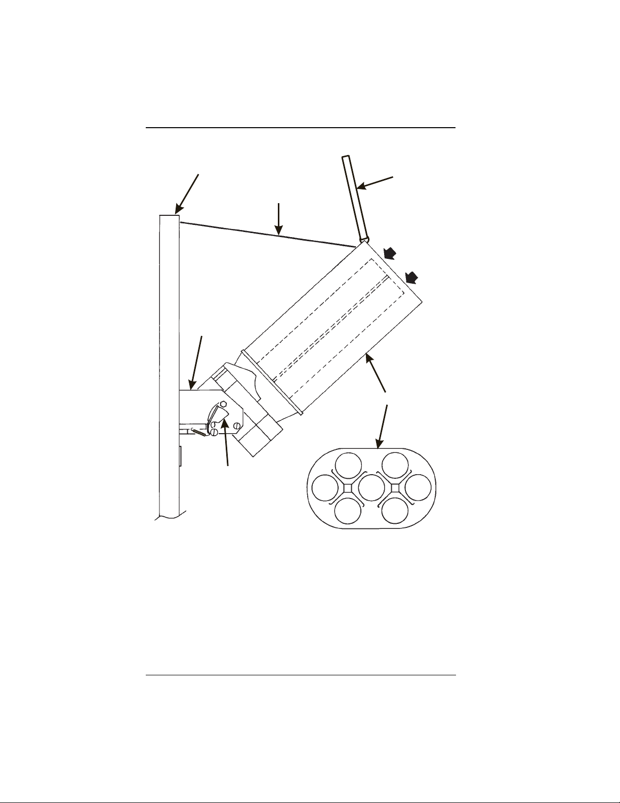
For a brewed selection, collect the water throws as follows:
1. Remove water supply hose from the brewer as shown on the next page.
7. Place the end of the hose in a graduated cylinder.
8. Follow steps 2 through 6 given for the non-brewed selection.
9. Replace the water supply hose on the brewer.
CUP FOR TAKING
CUP FOR TAKING
WATER THROWS
WATER THROWS
CUP DELIVERY
CUP DELIVERY
STATION
STATION
6390031 Page 43 July, 2001
Page 50

EUROTWIN OPERATOR ’S GUID E
Table W1. Water Throw Default Times and Volumes
Selection
5oz. 7oz. 8oz. 9oz. 10oz. 12oz.
A Fresh brew coffee
A Freeze dry coffee
B Fresh brew decaf
B Freeze dry decaf
D Espresso (F B)
D Espresso (FD)
FTea
GChocolate
H Soup or plain water
H Soluble Product 4.85
2.15
130
4.95
120
2.15
130
4.95
120
2.25653.20953.75
2.50603.50854.15
4.95
120
4.85
100
4.80
110
100
Time (in seconds) per size cup
Volume (in ml) per size cup
3.00
3.45
3.80
4.10
190
220
240
265
7.00
8.25
8.65
9.90
170
200
210
240
3.00
3.45
3.80
190
7.00
170
7.00
170
6.80
140
6.95
160
6.80
140
220
8.25
200
110
100
8.25
200
8.25
170
8.25
190
8.25
170
240
8.65
210
4.10
120
4.35
105
8.65
210
8.75
180
8.70
200
8.75
180
4.10
265
9.90
240
4.50
133
4.95
120
9.90
240
9.70
200
10.00
230
9.70
200
4.90
315
12.60
305
4.90
315
12.60
305
5.50
158
6.30
153
12.60
305
11.65
240
12.15
280
11.65
240
REMOVE THIS
TUBE
GRADUATED
CYLINDER
July, 2001 Page 44 6390031
Page 51

EUROTWIN OPERATOR’S GUIDE
SET UP A COLD DRINK
Be sure th at t he cu p size s yo u se t in SE T UP CU P SI Z ES agree with the cup s izes
actually in your machi ne. All procedures for setting up the cold drink s are similar, so
this example will demonst rate how to set up the 5 selection.
1. Press then until the display shows
1. Press 1 and 5. (For the "6" sel ection you would press 1 and 6, and so on.) The
display shows
cold water throw time for this selection is 6.80 seconds. Enter a new time if
desired.
2. Press . The display shows
set carbonated cold water throw time for this selection is 6.80 seconds. Enter a
new time if desired.
3. Pressing after each displa y will cause the following screen s to appear:
CLD. 15 6.80. This means that the curr ently set non-carbonated
CRB. 15 6.80. This means that the currently
SETUP -
b
.
SRP. 15 View and change the syrup throw time
PCT. 15 View and change the s etting s fo r the p ercen tage o f c arbonation
(0- 100)
4. At any of the preceding displays, you can press to test throw that item.
2. CONTINUE.
NOTE
The typical cold drink setup allows both a carbonated and still (noncarb) version. There may be cases when y ou w ish to serve o nly one
or the other.
To set up a still (non-carb) only, set the carbonat ion percentage
PCT. 15 . XX) to zero (PCT. 15. 00) . This setup will cause bot h ver-
(
sions to ve nd with no carbona tion.
To set up a carb only drink, set the desired c a rbonatio n level on the
percent screen, then press . The display shows an asterisk
to indicate this selection is carb only (
again to remove the aster isk and allow still drinks.
6390031 Page 45 July, 2001
PCT. 15 b XX). Press
Page 52

EUROTWIN OPERATOR ’S GUID E
COLLECTING COLD WATER AND SYRUP THROWS
1. Place a cup in the cup delivery station.
1. Ensure the merchandiser is using the facto ry defaults for the cup sizes (refer to
SET UP CUP SIZES, page 36).
2. Initiate the water (or syrup) throw for a selection.
3. Remove the cup and pour the liquid into a gradu ated cylinder.
4. Compare the measured throw to th e vo lume as shown in table W2.
5. Adjust throw times to get the desired volume.
6. If you are unable to get the right volume by adjusting the throw times, reset throw
times to the factory default, then adjust the w ater (o r syrup) valve for that selection (see ADJUSTMENTS AND MINOR MAINTENANCE, page 11). Repeat
steps 2 through 6 until the correct volume is thrown.
Table W2. Cold Water and Syrup Throw Default Times and Volumes
CUP SIZE
ML.OZ.ML.OZ. ML.OZ. ML.OZ.
177 6 25 0.85 2.5 125 4.2 4.25 125 4.2 4.25
207 7 30 1 3 150 5 5.25 150 5 5.25
244 8.25 36 1.2 3.5 181 6.1 6 181 6.1 6
266 9 40 1.4 4 200 6.7 7 200 6.7 7
296 10 45 1.5 4.25 222 7.5 8 222 7.5 8
355 12 50 1.7 4.5 250 8.5 9 250 8.5 9
SYRUP PLAIN WATER CARB. WATER
VOLUME
TIME
(SEC)
VOLUME
TIME
(SEC)
VOLUME
VIEW SOFTWARE VERSION
1. Press , and press until the display shows VER XXXXXX.
"XXXXXX" represents the current software version number.
2. CONTINUE.
TIME
(SEC)
July, 2001 Page 46 6390031
Page 53

EUROTWIN OPERATOR’S GUIDE
SET HOT AND COLD TEMPERATURE
0
1. Press then until the display shows 35
ple, 35 is the cold plate temperat ure setpoing and 202 is the water tan k temperature setpoin t in degrees Fahrenheit. If a decimal point appears next to the tank
temperature number, the heater is on . If a decimal poing ap pears n ext to the col d
plate temperature number, the compressor is on.
1. If desired, enter a new setpoint in the accepted range of 149° - 205° F (65° - 96°
C).
NOTE
The lower limit for vending is 10× below setpoint, up to a maximum
of 180× F (82× C).
2. To change display units (replace the "F" with a "C" for Celsius), press .
3. The cold plate temperature can be adusted between 34° and 49° F (1° - 9° C).
Press to increment to the next degree. Continue pressing to r o ll over
F 202
. In this exam-
back to 34° F.
CAUTION
Setting the cold plate temperature too low may res ul t in freezing the
plate. Be careful when adju sting the cold temperatur e.
2. CONTINUE.
6390031 Page 47 July, 2001
Page 54

EUROTWIN OPERATOR ’S GUID E
SET THE AUTOMATIC BREWER RINSE TI ME (BREWER
EQUIPPED MACHINES ONLY)
The brewer will be automatically rinsed by one of two methods: You can specify a set
time of day when the brewer is rinsed, or y ou can specify that ri nsing take s place a set
time after the last brewed selection is vended.
1. Press then until the display shows one of the following:
SAN.TIM 4.5 The time of day (in hours and tenths of hours) the machine
rinses the brewer. In this example, brewer rinse takes place
each day at 4:30 am. Range: 0.0 - 23.9 in .1 hour (6 minute)
increments.
OR
SAN.HRS 2.5. In thi s ex am ple, b rew er r i ns e t akes pl ac e 2 .5 hour s af ter t he l ast
vend. Rang e: 2.0 - 12. 5 hour s, in .1 ho ur (6 mi nu te ) inc r eme nts.
NOTE
If 24 hours passes without a vend, no rinsing will ta ke place. This
eliminates unnecessary rinsing over a weekend o r holiday.
1. Whichever one of the two choices i s d isplayed i s the method by which the b rewer
will be rinsed. Pr ess to switch between these two displays. Enter a
new time, if desired.
2. CONTINUE.
July, 2001 Page 48 6390031
Page 55

EUROTWIN OPERATOR’S GUIDE
SET THE AUTOMATIC MIXING BOWL RINSE TIME
Mixing bowl( s) can be automatically rinsed by one of two met hods: You can specify a
set time of day when the bowl is rinsed, or you can specify that rinsing takes place a
set time after the last selectio n is vended.
1. Press then until the display shows one of the following:
RIN.HRS 2.5 - This is how soon the machine r inses the bowls after a vend. In
this example, bowl rinse tak es place 2.5 hours after the last
vend. Range: 2.0 - 12.5 hours, in .1 hour (6 minute) increments.
OR
RIN.TIM 4.5 - Th e time of day (in hours and tenths of h ours) the machine
rinses the bowls. In this example, bowl rinse takes place at 4:30
am. Range: 0.0 - 23.9 in .1 hour (6 minute) increments.
NOTE
If 24 hours passes without a vend, no rinsing will ta ke place. This
eliminates unnecessary rinsing over a weekend o r holiday.
OR
RINSE OFF - No bowl rinse takes place.
1. Press to switch between these options, and the number keys to enter
new values.
2. CONTINUE.
6390031 Page 49 July, 2001
Page 56

EUROTWIN OPERATOR ’S GUID E
SET THE TI ME OF DAY
1. Press . The display shows TIME HH.MM. "HH.MM" is the time of day in
24-hour format.
1. Enter the current time using the number keys.
NOTE
9:00 am is entered with a leading zero, like this: 0900; 9:00 pm is
entered as 2100.
2. CONTINUE.
SET THE DAY OF THE WEEK
1. Press , and press until the display shows @ SMTWTFS. Th e
letter re presenting the curre ntly set day of the week will be flashing.
2. Press until the correct day of the week i s flas hing.
2. CONTINUE.
SET MONTH, DAY, AND YEAR
1. Press , and press until the display shows MM/DD YY. "MM"
is the month, "DD" is the date, YY is the year.
3. Enter the current month, date, and year using the number keys.
For example, press the following keys to enter February 22, 1996:
0, 2, 2, 2, 9, 6
4. Press to switch between MM/DD and DD/MM formats
July, 2001 Page 50 6390031
Page 57

EUROTWIN OPERATOR’S GUIDE
SET TIME-OF-DAY INHIBITED VENDING
Vending can be inhibited up to four times a day.
1. Press , then press until the display shows
1. Go to the TIME INTERVAL ED ITING procedure, page 52 for an example of how
to set up time-of-day inhibited vending.
INHIB - - - -.
SET TIME-OF-DAY FREE VENDING
Vending can be free up to four times a d ay.
1. Press , then press until the display shows
2. Go to the TIME INTERVAL ED ITING procedure, page 52 for an example of how
to set up time-of-day inhibited vending.
FREEV - - - -.
SET TIME-OF-DAY DISCOUNT VENDING
Vending can be discounted up to four times a day. For example, this can be used to
favor early- arriving employees..
1. Press , then press until the display shows
2. CONTINUE.Go to the TIME INTERVAL EDITING procedure, page 52 for an
example of how to set up time-of-day inhibited vending.
DISCT - - - -.
6390031 Page 51 July, 2001
Page 58

EUROTWIN OPERATOR ’S GUID E
TIME INTERVAL
EDITING
You can select up to four times of day for each special vending period.
NOTE
If two or more of these time periods overlap, the interval with the
highest priority will overrule the other(s). This order of p recedence
is:
1.INHIBIT
3.FREEVEND
4.DISCOUNT
For example, if a DI SCOUNT ti me period is sch eduled for a certain are a befor e th e end
of an INHIBIT time period, DISCOUNT does not begin until the INHIBIT interval has
ended for that area.
The time interval editing procedure is almost the same for the INHIBIT, FREEVEND,
and DISCOUNT intervals. There is one difference for the DISCOUNT time interval, so
we will use it in our example. Assume you ju st finished the SET TIME-OF-DAY DISCOUNT VENDING procedur e. Step 1 picks up where you left off . . .
1. The display shows
to edit, or to edit time interval 1 (we’ll use interval 1 for this example).
5. The display shows
your time interval (represented by 1) is on or off. Press to change the
condition of the time interval.
6. Press . The display shows
centage for this period. Enter a discount percentage of 25 with the number keys.
(Discount percentages of from 0 to 99 are permitted.) The machine will apply a
25% discount to each price, rounding up to the nearest nickel (or whatever is the
smallest coin accepted by the coin mechanism).
7. Press . The display shows
start time. Ente r a new sta rt time (24-hour format) for this interval. To enter the
time for 3:30 p m, enter 1530.
July, 2001 Page 52 6390031
DISCT - - - - . Press the number of the time interval you want
1.DISCT ON or 1.DISCT OFF. This display tells you whether
1.DSCT X . “X" r epresents the discount per-
1.STRT X.XX. “X.XX“ is the currently set
Page 59

EUROTWIN OPERATOR’S GUIDE
8. Press . The display shows 1.STOP X.XX. “X.XX“ is the c urrently set
stop time. Enter a new stop time (24-hour format) for this interval. To enter the
time for 6:00 pm, enter 1800. Yo u have now established a 25% d iscount that
starts at 3:30 pm and ends at 6: 00 pm.
9. Press . The display shows
days that this time interval is active. Pressing number keys 1 through 7 switches
the days on/off. For example, press "2", "4", and "6". The di splay now shows
1.@ - - - - - - - . The dashes represent th e
1.@ - M - W - F -. This discount interval is only active on Mond ay, Wednesday, and
Friday.
b
10. Press . The display shows
selections affected by this time interval. Press the appropriate letter key to enable
a selection, press the key again to disable it. For example, pr essing A, C, and E
will cause the display to look like this: A - C - E - - - -, meaning that all A, C, and E
selections are affected by this interval.
Advanced Options:
• Press to turn on all levels; press to turn all levels off.
• Press 0 or 1 to enable selections by cup size.
11. Press . The display shows
there is no custom message selected, and "X" repr esents the custom message
number set for this int erval. Press the number key of the message (1 through 8)
you want displayed. To edit this message, press and follow the proce-
- - - - - - - - - . The dashes represent the
1. MESG OFF or 1. MESG X. "OFF" means
dure gi ve n in EDIT CUSTOM MESSAGES, page 56. Press 0 to turn the message
OFF for this time interval.
2. CONTINUE.
6390031 Page 53 July, 2001
Page 60

EUROTWIN OPERATOR ’S GUID E
STANDBY
MESSAGE
The message that is di splayed during normal
vending periods when there ar e no out-of-ser vice
faults on the machine.
SELECT A STANDBY MESSAGE
1. Press , then pr ess until t he d ispla y sho ws STANDBY XX. "XX"
represents the current message number selected for the standby message. Two
dashes mean that the factory-set message is selected.
12. To select a message, just press the corr esponding number ( 1 through 8). To display the factory-set message, press 0.
13. The selected message (except the factory-set message) can be edited. To do
this, press and follow the procedure given in EDIT CUSTOM MES-
SAGES, page 56.
2. CONTINUE.
SELECT AN OUT-OF-SERVICE MESSAGE
1. Press , then press until the display shows SERVIC E XX. "XX"
represents the current message number selected to display when t he machine is
out-of-service. Two dashes mean that the factory- set message is selected.
14. To select a message, just press the corr esponding number ( 1 through 8). To display the factory-set message, press 0.
15. The selected message (except the factory-set message) can be edited. To do
this, press and follow the procedure given in EDIT CUSTOM MES-
SAGES, page 56.
2. CONTINUE.
July, 2001 Page 54 6390031
Page 61

EUROTWIN OPERATOR’S GUIDE
SELECT A FREEVEND MESSAGE
1. Press , then press until the display shows FREEVEND XX.
"XX" represents the current message number selected for the message that dis plays when the machine is in the freevend mode. Two dashes mean that the factory-set message is selected.
1. To select a message, just press the correspo nding number (1 through 8). To dis-
play the factory-set message, press 0.
2. The selected message (except the factory-set mess age) can be edited. To do
this, press and follow the procedure given in EDIT CUSTOM MES-
SAGES, page 56.
2. CONTINUE.
6390031 Page 55 July, 2001
Page 62

EUROTWIN OPERATOR ’S GUID E
EDIT CUSTOM MES S AGES
1. Press , and press until the display shows EDIT MSG’S . Press
the number of the mess ag e yo u want to edit.
sents the message number yo u pressed).
1. Press . The message text is displayed with the first character flashing.
2. To view the messag e, press . The message scrolls across the display.
To stop the scrolling, press .
3. When the character you want to change is flashing, either enter i t directly, or use
and to step through the character set until the desi red charac-
ter is displayed. Use the arrow keys to highlight different characters. See the
section on the next page for an explana tion of special keys and the character set.
SHORTCUT
Inste ad of ste pping through th e whole character set to enter a letter tha t i s n ot o n yo ur k eypad , en te r on e c lo se to the one yo u wa nt ,
then step to it. Example: If you want to enter an L, first press
to get an R, then press six times. Your L
should now be displayed.
MESSAGE X is displayed (X repre-
THE END OF MESSAGE CHARACTER
This is the most important character in your message, because it
tells the machine whe n the message is ended. If you don’t use this
character, your message will be followed by a bunch of nonsense.
This character can be selected either from the character set or by a
direct key entry (see the next page).
July, 2001 Page 56 6390031
Page 63

EUROTWIN OPERATOR’S GUIDE
ENTERING YOUR MESSAGE
Most of the keys on the control panel have a special purpose to help you create and
edit your messages:
Inserts an R at the flashing
character.
Inserts an S at the flashing
character.
Inserts a T at the flashing character.
Repeats the letter to the left of
the fl ashing character.
"Pages" through the message,
ten characters (one screen) at a
time.
Steps forward and backward through the message, one character at a time.
Steps forward and backward through the character list, one character at a time.
Inserts a space at the flashing
character.
Deletes the curr ent character
and closes up the space.
Deletes the curr ent character
and leaves the space.
Enters the special "end of message" cha rac ter , whi ch deno tes
the end of the message.
THE CHARACTER SET
0AKU [
1BLV]
2CMW#
3DNX
b
4EOY+
5FPZ->
6GQ
7HR_ .
8IS$<
(SPACE)
/?
@
o
9JT ‘ =
6390031 Page 57 July, 2001
Page 64

EUROTWIN OPERATOR ’S GUID E
VIEW WATER TANK AND COLD PLATE TEMPERATURE
1. Press . The display sh ows XXX
temperature, "YYY" is the current water tank temperature. "°F" means that both
temperature s are displayed in degrees Fahrenheit (may be shown in degrees Celsius, depending upo n your choice. See SET HOT AND COLD TEMPERATURE,
page 4 7). A decimal point shown in the display indicates that the tank heater or
compressor is operating.
2. CONTINUE.
O
F YYY. "XXX" is the current cold plate
VIEW MACHINE CONFIGURATION SETTING
1. Press , then press until the display shows D- J- WXYZ. See
SET UP MACHINE CONFIGURATION OP TIO NS, page 34, for an explanation of
this display.
1. Press . The display sho ws
tions for the regular size drink (0).
2. Press . The display shows
drink selection s fo r the regular size cup (0).
3. Press . The display shows
0. ABCDEFG-. This shows the active selec-
0. - - 56 - 89. This shows the active cold
1. ABCDEFG-. This sh o ws the active selec-
tions for the large size drink (1).
4. Press . The display shows
drink selections for the large size cup (1).
2. CONTINUE.
July, 2001 Page 58 6390031
1. - - 56 - 89. This shows the active cold
Page 65

EUROTWIN OPERATOR’S GUIDE
PAYO UT COINS
1. Press . If a dumb mech was selected, the display shows NDQ =123; if
an MDB mech was selcted the display sho ws
1. Press . A dumb mech pays out one
from tube 1. Press . A dumb mech pays out one
pays a coin fr om tube 2. Pr ess . A dumb mech pays o ut one
MDB mech pays a coin from t ube 3.
2. To continuously pay out coins, hold down the appropriate key.
2. CONTINUE.
PAY 123.
Nickel; an MDB mech pays a coin
Dime; an MDB mech
Quarter; an
6390031 Page 59 July, 2001
Page 66

EUROTWIN OPERATOR ’S GUID E
SET PRICES
1. Press . The display shows
imum and minimum prices set in the machine. In this example, the maximum
price is $2.50 and the minimum is $0.25.
1. Enter prices as using one of the following methods:
SET ENTIRE MACHINE TO ONE PRICE . . .
a. Press . The display shows
number keys. All selections in the machine are now set to this price.
SET THE PRICE OF AN INDIVIDUAL SELECTION . . .
a. Press the number of the selection to be priced. (Example: 1A.) The display
1A X.XX . Enter a price using the number keys. The selection is now
shows
pric ed.
b. Press another letter key, or to price another selection.
SET ALL CUP SIZES TO ONE PRICE . . .
You can set all regular drinks to one price, and all large drinks to a differen t pr ice:
a. Press 0 for regular size, or 1 for large size cups. If you pressed 1, the display
1b .XX .XX . This is the curr ently set minimum and maximum price.
shows
bb
2.50 .25 . This display shows the max-
bb
X.XX . Enter a price using the
b. Press . The display shows
c. Enter a price using the number keys. All large cup drinks are set to one
price.
d. Press to change the other si ze cup.
July, 2001 Page 60 6390031
1b .
Page 67

EUROTWIN OPERATOR’S GUIDE
SET ALL SIZES OF A SELECTION TO ONE PRICE . . .
a. Press a selection letter (A - H, X, Y, Z, 8, or 9). If you pressed C, the display
b
shows
pric e.
b. Press . The display shows
keys. All sizes of this selection are set to one price.
c. Press or another selection letter to change other selections.
2. CONTINUE.
C .XX .XX . This is the currently set maximum and minimum
b
C . Enter a price using the number
VIEW NONRESETTABLE SALES AND VEND DATA
1. Press . The display shows NR$ XX.XX. "XX.XX" is a dollar and cents
figure showing the total of all sales in the machine. This is a running total, and is
not resettable.
1. Press . The display shows
by the machine. This is a running total , and is not reset table.
2. CONTINUE.
6390031 Page 61 July, 2001
NR X. "X" i s th e t ota l nu mb er of ve nd s mad e
Page 68

EUROTWIN OPERATOR ’S GUID E
VIEW DATA THREE DIFFERENT WAYS
Paid sales and vends can be vi ewed three diff erent ways: By whole machi ne, by
selection, and by drink size within the selection. The first screen of the data item
shows its machine total.
• To view the data by selection, press the letter of the selection you want to see.
You can then press and to see data for all the active selections.
• To view the data by drink size:
1. Press 0 for regular size drinks or 1 for large size drinks.
2. Press the letter of the selection you want to see.
FOR EXAMPLE: To view the data for a large A selection, press 1A. The data will
be displayed.
You can then press and to see data for all the active selections
of that si ze .
VIEW TO TAL PAID SALES
1. Press , then press until the display shows
"XX.XX" is a dollar and cents figure showing the total of all PAID sales in the
machin e (a s o ppos e d t o un pai d sa les li k e w inner a nd fr ee vend s). This i s t he t ota l
since the last time it was cleared.
1. If desired, view this dat a by individual sel ection or drink size.
2. CONTINUE.
bb
$ XX.XX.
VIEW TOTAL PAID VENDS
1. Press , then pres s unti l the di spla y sho ws
total number of paid vends for the entire machine.
2. If desired, view this data by individual selection or drink size.
2. CONTINUE.
July, 2001 Page 62 6390031
bb
XX . "XX" is the
Page 69

EUROTWIN OPERATOR’S GUIDE
CLEAR ALL RESETTABLE DATA
1. Press . The display shows NR$ XX.XX. This is a running total, and is
not resettable.
1. Press and hold . Two beeps sound and the display shows
momentarily, and then changes to
2. CONTINUE.
FINI SHED. All data is cleared.
CLEA RING
CLEAR PAID SALES DATA ONLY
1. Press , then press until the display shows
"XX.XX" is a dollar and cents figure showing the total of all PAID sales in the
machin e (a s o ppos e d t o un pai d sa les li k e w inner a nd fr ee vend s). This i s t he t ota l
since the last time it was cleared.
2. Press and hold . Two beeps sound and the display shows
momentarily, and then changes to
data is not cleared.
2. CONTINUE.
FINISHED. All paid sales data is cleared; other
bb
$ XX.XX.
CLEA RING
VIEW AMOUNT IN COIN BOX (NOT SHOWN IF ZERO)
1. Press , then press until the display shows CBX XX.XX.
"XX.XX" is the dollar and cents amount in the coin box .
2. CONTINUE.
6390031 Page 63 July, 2001
Page 70

EUROTWIN OPERATOR ’S GUID E
VIEW AMOUNT IN VALIDATOR (NOT SHOWN IF ZERO)
1. Press , then press until the display shows DBV XX.XX.
"XX.XX" is the dollar amount in the bill stacker.
1. Press to show the quantities of bills in the stacker. For example, the dis-
play shows
Press again to show the quantities of other bills, such as $5s, $10s, or
$20s.
2. CONTINUE.
$01 20, meaning that there are 20 dollar bills in the bill stacker.
VIEW FREEVEND SALES BY TIME INTERVAL (NOT
SHOWN IF ZERO)
1. Press , then press until the display shows -0$ XX.XX.
2. Press , then press until the display shows
the total sales for freev end interval 1, shown even if zero.
3. Press to view intervals 2 through 4.
2. CONTINUE.
1.FRV .00. This is
VIEW DISCOUNT SALES BY TIME INTERVAL
1. Press , then press until the display shows
4. Press . The display shows
count interval 1 (not shown if zero).
5. Press to view intervals 2 through 4.
2. CONTINUE.
July, 2001 Page 64 6390031
1.DSC .00. This is the total sales for dis-
bb
$ XX.XX.
Page 71

EUROTWIN OPERATOR’S GUIDE
VIEW FREE VENDS (NOT SHOWN IF ZERO)
1. Press , then press until the display shows -0$ XX.XX.
1. Press , then press until the display shows
"XX.XX" is the total machine-wide freevends, sh own even if zero.
2. CONTINUE.
FRV XX.XX.
VIEW WINNERS (NOT SHOWN IF ZERO)
1. Press , then press until the display shows -0$ XX.XX.
2. Press , then press until the display shows WIN XX.XX.
"XX.XX" is the total machine-wide winners, shown even if zero.
2. CONTINUE.
6390031 Page 65 July, 2001
Page 72

EUROTWIN OPERATOR ’S GUID E
VIEW TIME DATA
1. Press , then press until the display shows TIME DATA.
1. Press . The following message scrolls across the display:
LAST POWER 01/30 13.51 FOR 00. 0.23
This example shows that the last ti me the machin e lost pow er was on January 30
(01/30) at 1:51pm (13.51) for zero days, zero hours, and 23 minutes (00. 0.23).
2. Press . The following message scrolls across the display:
LONGS.T POWER 01/30 10.58 FOR 00. 2.47
This example sho ws that the longest time the machine was without power was
on December 30 (01/30 ) at 10:58am (10.58) for zer o days, 2 hours and 47 minutes (00. 2.47).
3. Press . The following message scrolls across the display:
FULL CLEAR 01/30 8.58
This example shows that the last time resettable sales was fully cleared was on
January 30 (01/30) at 8:58am (8.58).
4. Press . The following message scrolls across the display:
TIME SET 01/30 9.15
This example shows that the last ti me the time or date was set was on Dece mber
30 (01/30) at 9:15 am (9.15).
5. Press . The following message scrolls across the display:
PRICE SET 01/30 9.42
This example shows that the last time prices were set was on December 30 (01/
30) at 9:42 am (9.42).
2. CONTINUE.
July, 2001 Page 66 6390031
Page 73

EUROTWIN OPERATOR’S GUIDE
VIEW TOTAL UNPAID SALES
NOTE
This does not appear if the total of unpaid sales is zero.
1. Press , then press until the display shows
"XX.XX" is the total unpaid sales (free vends, winner vends, 100% discounts,
zero price vend s) for the entire machine.
1. If desired, view this dat a by tray and individual selection.
2. CONTINUE.
_0$ XX.XX.
VIEW TOTAL UNPAID VENDS
1. Press , then press until the display shows _0 XX. "XX" is the
tota l number of unpaid vends for the ent ire machine.
2. If desired, view this dat a by tray and individual selection.
2. CONTINUE.
VIEW NUMBER OF TEST VENDS (NOT SHOWN IF
ZERO)
1. Press , then press until the display shows TST X. "X" is the
number of test vends.
3. If desired, view this dat a by tray and individual selection.
2. CONTINUE.
VIEW NUMBER OF MUG VENDS (NOT SHOWN IF
ZERO)
1. Press , then press until the display shows MUG X. "X" is the
number of mug vends.
4. If desired, view this dat a by tray and individual selection.
2. CONTINUE.
6390031 Page 67 July, 2001
Page 74

EUROTWIN OPERATOR ’S GUID E
VIEW MACHINE ID NUMBER
1. Press , then press or until the display shows I.D.
XXXXX X . The X’s represent the 6-digit machine ID number.
1. You can edit the machine ID number if the SUPERVISOR access code has been
previously entered.
2. CONTINUE.
TEST VEND SELECTIONS A ND VERIFY CREDIT
ADDED
1. Press . The display shows TEST .00. You may now test vend s elec-
tions. If you insert mo ney into the machine, the zeros in the display will be
replaced with the amount of the credit. After the item vends, your money will be
returned.
NOTE
You may make one more test vend if you c lose the door while still in
TEST VEND mode.
2. CONTINUE.
TEST THE DISPLAY
1. Press , then press until the display shows DSPLY TEST. The
"DRINK BEING SERVED" lamp is lighted, and remain s lighted until you leave
this function.
2. Press to light all display segments; press to turn them off.
3. Pressing a NUMBER KEY on the control panel causes all segments to display
that character.
2. CONTINUE.
July, 2001 Page 68 6390031
Page 75

EUROTWIN OPERATOR’S GUIDE
TEST DROP A CUP
1. Press , then press until the display shows CUP TEST.
1. Press to drop a cup.
2. CONTINUE.
TEST THE WHIPPER(S)
1. Press , then press until the display shows WHIP TEST.
2. Press the number corresponding to the whipper you want to test (1, 2, or 3). The
whipper runs for one second. Whipper numbers will be displayed while the whipper is running.
2. CONTINUE.
TEST THE AIR COMPRESSOR
1. Press , then press until the display shows AIR TEST.
3. Press to run the air compressor.
2. CONTINUE.
6390031 Page 69 July, 2001
Page 76

EUROTWIN OPERATOR ’S GUID E
TEST THE BREWER
1. Press , then press until the display shows BREW TEST.
WARNING
Keep away from the brewer mechanism while it is operati ng. Coming into contact with moving parts could injure you.
1. Press to test each brewer position:
BREW’R BR EW = The brewer is in the BREW POSITION.
BREW’R FLIP = The brewer is in the FLIP positi on.
BREW’R HO ME = The brewer is in the HOME posi tion.
2. CONTINUE.
RINSE THE MIXING BOWLS
1. Press , then press until the display shows BOWL RINSE.
2. Press to rinse the mixing bowls. The display shows
operatio n is com pl ete.
2. CO NTINUE.
RINSING until the
RINSE THE BREWER
1. Press , then press until the display shows BREW RINSE.
3. Press to rinse the brewer. The display shows
tion is complete
2. CONTINUE.
July, 2001 Page 70 6390031
RINSIN G unt il the opera-
Page 77

EUROTWIN OPERATOR’S GUIDE
PURGE TH E CAR B ONATOR
1. Press , then press until the display shows PURGE TEST.
1. Press to purge the carbonator without r efilling it.
2. CONTINUE.
CLEAR TANK ERRORS AND FILL THE TANK
1. Press then until the display shows TANK FILL.
2. Press . This clears any tank error and starts filling the tank, if necessary.
If it is taking a long time to fill the tank AND THERE ARE NO LEAKS, you may
see
TANK E RR in the diagnostic list again. Just pre ss again after mak-
ing sure there are no other problems, such as a restriction in the water inlet line or
a clog ged water filter.
2. CONTINUE.
TEST SWITCHES OR SENSORS
1. Press then until the display shows IN.MKPHL1.
3. Actuate each switch or sensor to test its function:
M = mug/cup sensor (if equipped) K = freevend keyswitch
P = waste pai l switch H = high wa ter ta nk lev e l switch
L = low water tank level switch 1 = ring 1 cup sensor switch
As you actuate each input , t he display element representing that switch blinks on.
Releasing the switch caus es that element to blink off again.
4. Press . The display shows
C = No CO
P = Carb tank low level.
2. CONTINUE.
6390031 Page 71 July, 2001
pressu re
2
IN. CP.
Page 78

EUROTWIN OPERATOR ’S GUID E
VIEW D IAG N O STIC MESSA GE S
1. Press . the display shows any of the following diagnostic messages,
depending upon any fault(s) present:
NO ER RORS None of th e following errors are detected:
KEYPAD XY Key(s) x, y stuck.
ROM ERROR Error in the programming EPROM. MACHINE WILL NOT
OPERATE.
RAM ERROR RAM is not initialized or is not compatible with the currently
loaded s oftware. If this message appears, initialize your RAM
by perf orming the following procedure:
NOTE: Initializing RAM will erase all your data and drink settings. Be sure you have written this information down before
continuing.
Press AND HOLD until two beeps are heard, and the
display sho ws
FINISH ED.
KEYSWITCH The keyswitch input i s actiave and configured as an inhibit.
D + J + WXYZ Configuration error; displays the machine configu ration screen.
NOTE: this is the actual config screen. You may enter the correct
config number directly on this screen without further action.
TANK ERR Tank failed to fill or refill.
RING . MTR The cup ring is jammed.
MTR 1A1B Cup turrets are jammed
NO CU PS Ou t of cups.
BREW JA M The brewer is jammed.
WASTE PAIL The waste pail is full.
LOW WATER The water level in the tank is low.
COLD WATER Water in the tank is too cold to vend.
WARM PLATE The cold plate is warm.
OVERTEMP Inlet water is too warm to operate compressor
SENSOR 1 2 Temp sensor failed or missing 1 = float sensor, 2 = coldplate.
WHIP 1 2 3 Whipp er moto r fa ilu re (m oto r 1, 2, or 3).
DOOR JAM The automatic delivery door is jammed.
NO CO 2 CO
pressure is low
2
.
SYRUP 1 2 Syru p ta n k (s ) are lo w (t a nk 1, 2 ).
July, 2001 Page 72 6390031
Page 79

EUROTWIN OPERATOR’S GUIDE
NO MECH Coin mech not detected - machine will not operate if configured
for coin mech.
MECH COMM Incomplete coin mech communications — check harness.
MECH.SENSOR Coin mech repor ting a bad tube sensor — repl ace mech.
MECH ROM Replace the coin mechanism.
MECH.ACCEPT Coin mechanism acceptor section is unplugged from the main
body of the coin mech. Connec t th e cable and cycle machine
power OFF and then ON.
MECH JA M One or more coin tubes are jammed. Pay a coin from each tube
until the jam is cleared.
DEBIT CARD Car d r eader reporting error — machine will not operate if config-
ured for DEBIT ONLY.
CHECK DBV Bill validator reporting er ror — machine will not operate. Empty
stacker, clear jams, etc.
DBV C OMM Incomplete bill validator commun ications — check harness.
DBV MOTOR One of the motors has failed. The unit will disabl e itself until the
error is corrected. Check for bill stuck in the accept ance path. If
no bill is p rese nt, r eplace the val idator. Cycle machine power OFF
and then ON.
DBV SENSOR One of the sensors in the bill validator has failed. The unit will dis-
able itself until the error is corrected. Check for bill stuck in the
acceptance path. If no bill is pr esent, re place t he validator. Cycle
machine power OFF and then ON.
DBV JAM A bill is j ammed in t he accept anc e path. T he unit will d isabl e itsel f
until the error is corrected. Remove bill stuck in the acceptance
path. Cycle machine power OFF and then ON.
DBV STACKR The stacker is o pen or removed. The unit will di sable itself until
the error is corrected. Install the stacker co rrectly.
CHK PRICE Pr ice error detected and changed to maximum - check prices.
NONE READY all selections are reported out of service.
6390031 Page 73 July, 2001
Page 80

EUROTWIN OPERATOR ’S GUID E
DOWNLOAD DATA TO A PDCD
1. Connect your portable data collecti on device (PDCD) in accordance with its
operating instructions.
1. Press . Data is downloaded into your PDCD.
NOTE
Depending upon the setting selected in set PRINTER OR DEX
options, data may be cleared after the download is complete.
2. CONTINUE.
SET FREEVEND OPTIONS
1. Press until one of the following is displayed:
FREE OFF - Normal vending mode. No items are on freevend. (A clo sure
on the optional keyswitch input ca uses the machine to go out
of service.)
- OR -
FREE ALL - All items are on freevend. The credi t display shows
NO MO NEY REQUI RED
(A closure on the optional keyswitch causes the machine to go ou t of service.)
- OR -
FREE W/KEY - All items are freevended while there is a closure on the optional
keyswitch input. Normal cash sales are supported when the
option a l keys w it c h input is open.
- OR -
FREE ONCE - A closure on the op tional keyswitch input causes only the next
item to be freevended. Coin mechan ism errors are ignored.
this state is designed fo r card or token sys tems wher e one it em
is vended per token. Normal cash sales ar e also supported.
2. Press until the option you want is displayed.
NOTE
See Appendix D for more inform ation on the freevend keyswi tch.
2. CONTINUE.
July, 2001 Page 74 6390031
Page 81

EUROTWIN OPERATOR’S GUIDE
CLEANING AND SANITATION
BASICS
INTRODUCTION
Anybody who services vending machines must use proper sanitizing pr ocedures.
Health regulations require that hands be clean when cups, comm od ities, and foodcontact parts are handled or serviced.
In addition, Health Departments require regular cleaning and sanitizing procedures for
food contact parts.
The information in this section will explain how to clean and/or sanitize the merchandiser on a regular basis. A clean and well maintained merchandiser will provide a better product and greater safety for your customers.
CLEANING AND SANITIZING -- WHAT’S THE DIFFERENCE?
CLEAN means “free of visible soil”. In cup vending machine servicing clean ing is
done to maintain product quality and to remove food soils, oils, and mineral stains that
could affect pro duct taste, aro ma, and appearance.
SANITIZING means the redu ction to safe levels of the number of disease-causing
bacteria that remain on the surface after cleaning. Therefore, cleaning and sanitizing
are done in separate steps, as prescribed by health regulations and good industry
practice.
When you sanitize you create a healthy and hygieni c condition. This leads t o whol esome foo d , which in turn leads to satisfied customers.
SANITIZING IS NO SUBSTITUTE FOR GOOD CLEANING
HOW DO I SANITIZE?
You can sanitize by using either of these two methods:
Chemicals: The object to be sanitized is treated with a bactericidal compound.
Heat: Raise the temperature of the object to be sanitized high enough to kill
bacteria. Wat er must be at least 77
Hot brew water (if available) is an acceptable sanitizer.
tact surfaces are washed and/or rins ed, use the h o t water avai lable in the
machine.
Be sure to turn the machine off bef ore using water on the machine.
In either case, the object to be sanitized must be thoroughly clean and completely
rinsed in order for the sanitizing process to work. Caked-on soils, not removed by
cleaning for example, may shield bacteria from a sanitizing solution.
6390031 Page 75 July, 2001
o
C (170oF).
When food-con-
Page 82

EUROTWIN OPERATOR ’S GUID E
NOTE
Hot brew water may cause damage to some parts of the cooling
system and should not be used in any proced ure unless specifically
stated.
Where “W arm W ate r” is s uggest ed the t emperatur e is desig nated t o
be a maximum of 50
A GOOD PLACE TO START -- YOU R SANITATION KIT
You need to be sure that each machine is clean, safe and functionin g when you leave
the location. In order to properly do th is, you need to have a co mplete set of the right
tools.
Here is a checklist of the items needed for a good sanitation kit:
Sanitation pail
Tube and nozzle brushes for food contact surfaces
Utility brush for dry spillage around canisters, etc.
Disposable towels, wet-strength and lint-free
Wiping with towels can recon tami nate sanit ized food -contact pa rts.
Therefore, towels should not be used to dr y foo d-co ntact surfaces.
Instead, these parts should be air dried.
o
C (122oF).
NOTE
Spra y de t e rge n t , diluted to de s ir e d st rength
Urn cleaner packets for coffee stain s and oils
Odor control chemical s for pails
Replacement parts (if the exchange method is used)
Cabinet polish or window cleaner for the outside of the machine
Feel free to add som e items to this list. For example, you may want to use a portable
vacuum cleaner.
July, 2001 Page 76 6390031
Page 83

EUROTWIN OPERATOR’S GUIDE
OVERALL CLEANING
Inspect your merchandiser both inside and out. Be sure to check corners and all less
visible parts of the merchandiser.
Clean where needed.
Allow the inside of the cabinet to dry thorou ghly before you close th e do or.
PREVENTIVE MAINTENANCE CLEANING
Periodically, you should visually inspect your merchandiser’s hot water tank for excessive lime and scale buildup. This buildup on the tank w alls, water valves and heater
element will vary dramatically, depending upo n water quality. You should develop a
cleaning and deliming schedule based o n the apparent local water quality.
NOTE
To aid in removing scale from your merchandiser, National Vendors
has a service kit availabl e: part number 6400080. In addi tion, if
your machine has the Everpure water inlet filter syst em option, a
second kit: part number 6400086 is also availabl e.
CLEANING PROCEDURES
Non Food-Contact Parts
Cup Delivery Compartment - Remove the cup delivery compartment from the
merchandiser. Thoroughly wash the cup delivery compartment usin g a clean,
damp, disposable paper wiper. Rinse with clean, hot, flowing wat e r. Reinstall.
Cabinet Cup Delivery Door
Waste Bucket
and rinse with hot water. Sprin kl e detergent powder in the bottom of the waste
bucket to help control odors. Be sure to replace the overflow switch float.
Grounds Pail
with a clean plastic bag.
Brewer Mechanism
rinse with hot water.
Cooling Sy s t em
damp, disp os able paper wiper.
Ingredient Rinse Tray
water .
Exhaust Fan Filter
water, rinse, wring dry and replace into housing.
Cabinet Door
wiper.
Condenser
screwdrivers or sharp objects which may puncture the condenser, requiring
repairs.
- Empty, wash with a chlorinate detergent or equivalent chemical
- Empty, wash and rinse with hot water. Reline the grounds pail
- Wipe the top cover, any visible tubes and sides with a clean,
- Remove the filter from its housing. Wash with soap and
- Wipe the inside and out with a clean, dam p, disposable paper
- Clean with a small stiff brush. Avoid poking between the fins with
- Wash with a clean, damp, disposable paper wiper.
- Remove the brewer mechanism from its mounting and
- Remove product canisters. Wash and rinse with hot
6390031 Page 77 July, 2001
Page 84

EUROTWIN OPERATOR ’S GUID E
SANITATION PROCEDURES
Food-Conta ct Parts
All food-contact parts must be cleaned and sanitized. Air dry, do not wipe dry.
Ingredient Canisters
augers and spouts with hot water and allow to air dry before returning to cabinet.
Mixing Bowls
“Bowl Rinse” operation as outlined in the Programming section of this manual.
If needed, remove the mixing bowls fro m the dry ingredient s helf. Clean and san-
itize the mixing bowls by washing with hot water. Allow to air dry before reassembling.
Whipper Caps and Impellers
housings. Clean and sanitize the caps and impel ler housi ng by washing with hot
water and allow to air dry before reassembling.
Hot Beverage Di s charge No zz les
ing tubes from the nozzles. Remove the nozzles from the mounting bracket.
Remove the cap from each nozzle. Dip the tube cleaner brush in a sanitizing
solution and thoroughly clean the nozzles and caps inside and out. Rinse th e
tube cleaner brush thoroughly with clean, hot wat er and brush the nozzles thoroughly between each rinse. Use a clean, damp, disposable paper wiper. Rinse
with clean, hot water and dry thoroughl y before reinstalling.
Cold Beverage Discharge Nozzles
pense tubes from the hold er by releasing the two thumb screws. Immerse the
dispense tubes in warm water to remove an y external deposits and brush clean.
Clean inside the tube s with a sma ll brush. Flush with warm wa ter. Reinstall nozzles.
Syrup Tubes
tubes from the pr oduct container, and place them in a container of warm water
and test throw until clear water comes out of the dispense nozzle.
Place the dip tubes into the conta iner of sani tizi ng fluid. Perform t est thr ows unti l
the fluid pours from the dispense nozzle. Leave stand for the period recommended by the manufact urer of the sanitizing fluid (usually 10 to 15 minu tes).
Place the syrup dip tubes in a 5 - litre co ntainer of clean, cold water and flush 1
litre through each syrup line using the test throw procedure.
- First ensure that th e waste bucket is in place. Lift the sy rup dip
- Empty and clean and sanitize by was hing the canisters,
- The inside of all mixing bowls may be rinsed by performing the
- Remove caps and impellers fro m the whipper
- Disconnect all of the hot beverage dispens-
- Clean by removing the stai nl ess steel dis-
July, 2001 Page 78 6390031
Page 85

EUROTWIN OPERATOR’S GUIDE
Cold Water System - Ensure that the waste bucket is in place. Empty the carbonator by test throwing carbonated water until you hear sputtering at the dispense nozzle.
Remove the Everpure filter. Load an Everpure sterilizi ng (dummy) cartridge with
2 fluid ounces of Milton 2 fluid and fit the cartridge to the machine.
Test throw st ill (non-carbonated) wa ter to clear any air locks. Release and allow
the carbonator to fill with solution.
T es t throw both carbonated water and still water once more to ensure that all of
the tubes are full of the sanitizing fluid.
Switch power “OFF” and allow the machine to stand loaded with the sanitizing
solution for 10 minutes. To flush out the sterilizing solution, remove the dummy
cartridge and r epl ace the Everpu re fi lter. Switch power “ON”. V en d 3 litre s of st ill
water from the machin e then vend 3 litres of carbonated water.
Brewer, Brewer Basket and Brewer Funnel
cleaned and sanitized by performing the “Brew Rinse” operation as outlined in
the programming section. The machine features an auto mat ic brewer sanitizing
feature also described in the pro g ramming section.
At times, it may become necessar y to clean and sanitize the individual brewer
parts. If this should occ ur, disconnect the tubes from the brewer manifold.
Remove the b rewer barrel and manifold assembly fro m i ts support. Remove the
brewer basket and funnel assemblies. W ash all parts using a chlor inated detergent or equivalent chemical. Rinse thoroughly with hot water.
- The tubing and brewer may be
6390031 Page 79 July, 2001
Page 86

EUROTWIN OPERATOR ’S GUID E
SYRUP
CARBONATED
WA TER
NON-CARBONATED
WA TER
SYRUP
COLD DRINK TUBE ROUTING DIAGRAM
July, 2001 Page 80 6390031
Page 87

EUROTWIN OPERATOR’S GUIDE
FROM
CHOCOLATE
BOWL
FROM
SOUP
BOWL
FROM
CONDIMENT
BOWL
FROM HOT
WATER VALVE
HOT DRINK TUBE ROUTING DIAGRAM
6390031 Page 81 July, 2001
Page 88

EUROTWIN OPERATOR ’S GUID E
RECOMMENDED CLEANING AND SANITATION INTERVALS
CS
CS
ITEM D AILY WEEKL Y MONTHLY QUARTERLY SEMI-ANNUALLY
Ingredient Canisters C S
Mixing Bowls C S
Whipper Lids and
Impellers
Beverage Dischare
Nozzles
Cup Delivery Com-
partmentCExhaust Fan Fi lter C
July, 2001 Page 82 6390031
CS
Waste Pail C
Brewer, Basket, Fun-
nel
Coffee Chutes C S
Brewer Mechanism C
Grounds Pail C
S = Sanitize at this interval C = Clean at t his interval
Page 89

EUROTWIN OPERATOR’S GUIDE
APPENDIX A. THE INFRARED MUG/CUP SENSOR
The infrared mug/cup sensor can sense the presence of a mug or cup without usin g
moving parts.
Indicator lig ht
The sensor is equipped with an indicator light. This light will help you get the best
results from the infrared mug/cup sensor.
Under these conditions:
• Machine door open
• Cup station in place
• No cup in the station
The in dicator light should be off. If it is on, it is indicating imprope r cup station alignment or excessi ve sensor se nsitivity.
Under these conditions:
• Machine door closed
• Cup station in place
• No cup in the station
Press any letter on the selecti on switch panel, for example, A. Only th e let te r A should
be showing in the message displa y. If
the following:
• Improper cup station alignment
• Excessive sensitivity (the sensor is se nsing the deliver y door)
• Cup station lens is not clean
Cleaning
As indicated in the Sanitation section, you should remove the cup stati o n to clean it.
Pay particular attention to the d ark colored infrared mug/cup sensor lens, which is
part of the cup station. I f it is not thoro ughly c leaned, the sensor will not work properly.
A MUG is displayed, it indicates one or more of
CAUTION
Do not get liquid inside the sensor unit.
Cleaning the i nfrar ed mug/cup sensor unit itself is not usually necessar y. If it does
require cle aning, just wi pe it with a damp clot h.
6390031 Page A-1 July, 2001
Page 90

EUROTWIN OPERATOR ’S GUID E
Calibration
1. Remove the plastic cap in the rear of the sensing unit, exposing the potent iometer adjusting screw, as shown in figure A1.
3. Turn the screw clockwise to increase sensitivity of cup detection, or counterclockwise to decrease sensitivity .
4. Calibrate the sensor:
CAUTION
Do not adjust sensitivity too far, or unreliable sensing could result.
a. Using a piece of WHITE poster board or heavy cardboa rd, make a 5" x 5-5/
8" target.
NOTE
It is very important that this material be white.
b. Place the target in the cup station just beyond the cup deflectors (see figure
A-2). The target should be standing vertically; not tilte d forward or backward.
c. With the target in place, turn the adjusting screw clockwise very slowly u ntil
the indicator just turns ON.
d. Turn the adjusting screw counterclockwise very slowly until the indicator
just turns OFF .
1. Replace the plastic cap.
2. Insert a mug into the cup sta tion in t he vend ing posi tion a nd c heck to see t hat th e
red indicator light is ON.
This calibration will be adequate for most cups or mugs. In some cases, a slightly
more sensitive setting is needed if the cup or mug is a dark color.
July, 2001 Page A-2 6390031
Page 91

EUROTWIN OPERATOR’S GUIDE
VIEWING REAR OF SENSOR ASSEMBLY
INDICATOR
LIGHT
ADJUSTING SCREW
PLASTIC CAP
CUP
Figure A-1
Figure A-2
PLASTIC CAP
SHOWN REMOVED
INDICATOR LIGHT
CUP
DEFLECTORS
6390031 Page A-3 July, 2001
Page 92

EUROTWIN OPERATOR ’S GUID E
L
L
NA
Y
L
E
T
F
B
NK
A
L
TIO
N
E
NT
I
IS
GE
A
P
S
HI
T
July, 2001 Page A-4 6390031
Page 93

EUROTWIN OPERATOR’S GUIDE
APPENDIX B. MODIFY CANISTER TO VEND 12 OZ.
CUPS
Proceed as follows:
3. Remove all cups, then remove the turret c enter and turret base assembly from
the canis t er.
4. Break off all 8 tabs on the bottom o f the turret base as shown.
NOTE
You will no longe r be ab l e to vend smaller c up s from this can is te r!
To return to vending smaller cups you must rep lace the modified turret base with an original turr et base (part number 6233048) from
National Vendors Parts Department.
5. Replace the turret center and turret base in the canister and load cup s.
6. Drop a cup. If it drops properly, you are finished with the pr ocedure, if not, con-
tinue with step 7.
7. Remove all cups, then remove the canister fro m the cup mechanism assembly.
8. Remove the funnel, replace the canister, and reload cups.
9. Drop a cup. If it drops properly, you are finished with the pr ocedure, if not, con-
tinue with step 10.
10. Order a 5 oz/18oz cup ring (part number 6233120) fr o m Nat ional Vendors P arts
Department.
6390031 Page B-1 July, 20 01
Page 94

EUROTWIN OPERATOR ’S GUID E
TURRET
CENTER
TURRET
BASE
BREAK OFF
ALL TABS
CANISTER
639p0079
July, 2001 Page B-2 6390031
Page 95

EUROTWIN OPERATOR’S GUIDE
APPENDIX C. CLEAN THE HOT WATER TANK
Some smell and/or t aste problems may occur in new machines. F ollow this pr oc edur e
to clean the hot water tank if you experience prob lem s:
11. If the machine is in service, remove power fro m t he m achi ne.
12. Dissolve 1 tablespoon of common baking sod a in a cup of water.
WARNING
The water tank may be HOT. Be careful when working on the tank.
13. Loosen or remove the hot water tank lid and pour the baking soda solution into
the tank.
14. Apply power to the mac hine.
15. If the tank is not full, fill it.
16. Allow the tank to reach its operating temperature.
17. Leave the solution in the tank for AT LEAST
tion in the tank for 1 hour.
18. Drain the tank.
19. Refill the tank, then drain again.
20. Refill the tank and put the machine back into ser vice.
½ hour . If possible, leave the solu-
6390031 Page C-1 Jul y, 20 01
Page 96

EUROTWIN OPERATOR ’S GUID E
L
L
NA
Y
L
E
T
F
B
NK
A
L
TIO
N
E
NT
I
IS
GE
A
P
S
HI
T
June, 2001 Page C-2 6390031
Page 97

EUROTWIN OPERATOR’S GUIDE
APPENDIX D. THE FREE VEND KEYSWITCH OPTION
The free vend keyswitch all ows someone to set up free vending with o ut needing to
open the door.
NOTE
Freevend Options MUST be set to FREE W/KEY (see the program-
ming section) for this to work properly.
TO START FREE VEND:
2. Place your key in the free vend keyswitch an d turn it to t he rig ht. (If t he keyswit ch
is already turned to t he rig ht, turn it t o the l eft, t hen back to t he right. ) The dis play
ENTER CODE.
shows
3. Enter the four-digit free vend code. If you enter the wrong code, you have to
return to step 2 and start over.
4. If you enter the correct code, the display shows:
5. Remove your key. NOTE: You don’t have to turn the key back to the left to
remove it, but it’s a good idea to do so.
TO END FREE VEND:
1. Place your key in the free vend keyswitch an d turn it to t he rig ht. (If t he keyswit ch
is already turned to t he rig ht, turn it t o the l eft, t hen back to t he right. ) The dis play
ENTER CODE.
shows:
2. Turn the keyswitch back to the left and remove your key. The display returns to
the standby message.
TO ELIMINATE THE CODE REQUIREMENT:
1. The factory default code is 0000. If this code is used, the machine will not ask for
a code, but will simply enter freevend mode.
2. To requir e a CODE entry, change the code to something other than 0 000 (see
ENTER A NEW FR EEVEND CODE in the programming section).
NOTE THAT NO CODE IS NECESSARY TO REMOVE THE
MACHINE FROM FREE VEND.
FREE ON.
6390031 Page D-1 Jul y, 20 01
Page 98

EUROTWIN OPERATOR ’S GUID E
L
L
NA
Y
L
E
T
F
B
NK
A
L
TIO
N
E
NT
I
IS
GE
A
P
S
HI
T
July, 2001 Page D-2 6390031
Page 99

This Merchandiser is warranted for one (1) year against defective parts and workmanship. Any part or parts which are proven to be defect ive within one ( 1) year of the date
of shipment will be r epaired or r eplaced free of charge when the defective part is
returned, with transportation char ges prepaid, to th e destination designated by the
National Vendors Warranty Department.
This warranty applies only to the original purchaser of the Merchandiser and is null
and void if the Merchandiser is sold during the period of warr anty.
This warranty do es not apply t o a) electrical components, wiring, or circuit s and/or for
all mechanical parts or assembl ies damaged as a r esu lt of oper ating the Mer cha ndiser
at other than the design voltage and frequen cy specified on the Electrical Rating Tag,
or b) in event of vandalism, fire or negligence, or c) incandescent lamps, neon lamps,
fluoresce nt la mps, ballasts, starters or other expendable item s o r d) when other manufactured components are installed in Nati o nal Vendors Merchandisers.
National Vendors is not respons ibl e for any cost of service rendered or repairs ma de
by customer or its agents on Mer chandiser or par ts unless authorization to incur such
expense has been given in writing by National Vendors prior to incurring such
expense.
THIS WARRANTY IS IN LIEU OF ALL OTHER WARRANTIES EXPRESSED OR
IMPLIED, INCLUDING WITHOUT LIMITATION, WARRANTIES OF MERCHANT A BILITY
OR FITNES S F OR A PARTICULAR PUR POS E. NATIONAL VENDOR S SH ALL N OT BE
RESPONSIBLE FOR CONSEQUENTIAL OR PUNITIVE DAMAGES. National Vendors
neither assumes nor aut horizes an y person to as sume for it any obligati on or l iability i n
connection with the sale of sa id equipment or any part thereo f.
 Loading...