

Page 1

Page 2

This machine has been engineered to our own rigid safety and performance standards. It
has been designed to comply wit h sanitation and health guidelines r ecommend ed by the
Auto matic Merchandising Health-Industr y Council (AMHIC) and it conforms w ith all other
NAMA safety recommendations.
This machine has been manufactured in accordance with the safety standards of both
Underwriter’s Laboratories and the Canadian S tandards Association. To maintain this
degree of safety and to cont inue to achieve the level of performance built into this machine,
it is important th at installation and maintenance be per formed so as to not alter the original
construction or wiring and that replacement parts are as specified in the Parts Manual. Your
investment in this equipment will be protect ed by usi ng this Operatos’s Guide and the
Parts Manual in your op er a tio n, servic e and main te nance wor k . B y fol lo w in g prescrib e d
procedures , machine performance and safety w ill be preserved .
Crane Merchandising Systems Parts and Support
Parts: 1-800-621-7278 Service:1-800-628-8363
Page 3

TABL E OF C O N TE N TS
Initia l S e t-up.......... ...... ...... ...... ...... ...... ...... ...... .......... ...... ...... ...... .. 1
Power Re q u i r e m e n t s ......... ...... ...... ...... ...... ...... ...... ...... .......... ...... .... 1
Wate r Re q u i rements......... ............ .................. ............ ............ ......... 1
Final Installation ............................................................................. 2
Install Options................................................................................. 4
Get The Ma ch i n e Re ady To Vend D rinks ...... ...... ...... ...... ...... ...... .. 7
Adju stments a n d Minor Mai n tenanc e... ............ .................. ..... 12
Programming The Cold Drink Center...................................... 17
Getting Around ............................................................................. 17
The Disp l a y s ........... ...... ...... ...... ...... ...... ...... ...... .......... ...... ...... ...... 18
The Fun c t i o n Key s.......... .......... ...... ...... ...... ...... ...... ...... ...... ...... .... 1 8
Other Keys .................................................................................... 18
Some Conventions:....................................................................... 19
Control Panel Switch Functions Explained .................................. 20
SureVend™......... ...... ...... ...... ...... ...... ...... ...... ...... ...... ...... .......... .... 2 1
The Sup e r v isor Mode.. ...... ...... ...... ...... ...... ...... ...... ...... ...... .......... .. 22
Programming Procedures.......................................................... 23
Gain A cc e ss To The Su p ervisor Mo d e........ .................. ............ ....23
Enter A New Supervisor Code.......................................................23
Ente r A Freeven d Co d e.... ............ ............ .................. .................. ..23
Ente r a N e w D a t a Re ca l l Code .... ...... .................. .................. ........24
Lock Or Unlock Mode or Payout Keys .........................................24
Set Talker Mode.............................................................................25
Set Pr int er or DEX Mo d e.. .......... ...... ...... ...... ...... ...... ...... ...... ...... ...25
Set Dex Options.............................................................................26
Select Printer Baud Rate................................................................26
Select Display Language................................................................27
Select Coin Me chanism ... ...... ............ ............ ............ .................. ..2 7
Select Bill Va l i d a t o r and Optio n s.... ...... .................. ............ ..........28
Initial Setup Of NonStandard Bill Validator .................................29
Select Card R ea d e r a n d Opt i o n s.... ............ ............ .................. ......3 0
Select Monetary Options ...............................................................30
Set Up Winner Mode .....................................................................33
Set Up Mug Discount ....................................................................34
Disable Selections in the Merchandiser.........................................34
Page 4

Set Up Cu p Si zes ..... ...... ............ .................. ............ .................. ....35
Set Up A Drink ..............................................................................36
Facto ry Defau l t Th row Tim es and V o l u m e s............. .................. ..3 7
Blende d Drinks ....... ...... ...... ...... ...... ...... ...... ...... ...... ...... ...... ...... ..... 3 8
Configure Pump Type....................................................................39
Configure Number of Selections ...................................................40
Set Up Au t o m a t ic Delivery Doo r Op tions........ ...... ...... ...... ...... ..... 4 0
Assign Cup Sizes to Selections......................................................41
Turn SureVend™ On or Off ..........................................................42
Optio n a l o r Mandato ry S u reVend ™...... .. ...... ............ .................. ..42
Set Up the SureVend™ Anti-Jackpot Timer .................................43
View Software Version..................................................................43
Set the Time of Day.......................................................................44
Set Month, Date, and Year.............................................................44
Set Daylight Savings Time Options...............................................44
Set Time-of-D a y In h i b i t Vendin g................ .................. ................45
Set Time-of-Day Free Vending .....................................................45
Set Time-of-Day Discount Vending..............................................45
Time Interval Editing.....................................................................46
Select a Standby Message..............................................................48
Select an Out- o f-Service Mes sa g e........... .................. ............ ........4 8
Select a Freevend Message ............................................................49
Edit Cu st o m Me ssage ... ...... ...... ...... .......... ...... ...... ...... ...... ...... ...... .4 9
View Machine Configuration Setting............................................51
View Cu p Si zes Assi g n ed to Sele c t i o n s...... ...... ............ ................52
Payout Coins.................................................................... ..............52
Set Prices........................................................................................53
View No n re settab le Sale s an d Ven d D at a .. ...... ...... ...... ...... ...... ..... 5 3
View Data Four Different Ways....................................................54
View Total Paid Sales....................................................................54
View To t a l Sales By D ri n k Si ze...... ............ .................. ............ ....54
View Total Sales By Selection ......................................................54
View To t a l Sales By Ind i v i d u a l S e l e ction....... .................. ............55
View Total Paid S a l es By Pr ice Line...... ...... ...... ...... ...... ...... ...... ...55
View To t a l Paid Vend s.. ............ .................. ............ .................. ....55
Clear A ll Re setta b l e D a t a...... ...... ...... ...... ...... ...... ...... ...... ...... ...... ...56
Clear Paid Sales Data Only............................................................56
View Amount in Coin Box ............................................................56
Page 5

View Amount in Validator ............................................................57
View Fr e e v end Sales by Time Int e rv al...... .................. ..................57
View Discount Sales by Time Interval..........................................58
View Fr e e Ve n d s............ ............ .................. ............ .................. ....58
View Winners ................................................................................58
View Time Data.............................................................................59
View To t a l Unp a i d S a l e s................... ............ .................. ............ ..6 0
View Total Unpaid Vends .............................................................60
View Nu mb er of Test V e n d s ...... ...... ...... ...... ...... ...... ...... ...... ...... ...61
View Nu mb er of Mug Ve n d s.. ...... ...... ...... ...... ...... ...... ...... ...... ...... .61
View Number Of Alt Vends..........................................................61
View Machine ID Number.............................................................61
View Cup Ring Cycles Related to SureVend™............................62
View Nu mber of Cup Ring Cycle Failures. ...... ...... ...... ...... ...... ..... 6 2
View Home Switc h Us e Relate d to S u re V end ................ ..............6 2
Test Vend Selections and Verify Credit Added.............................63
Test t h e Displa y........... ............ .................. ............ .................. ......63
Test D ro p a Cup......... ............ ............ ............ .................. ............ ..6 4
Test the Automatic Delivery Door.................................................64
Test Th row Still Wate r .................. ............ .................. ............ ......6 4
Test Throw Carbonated Water.......................................................64
Test the S y ru p Pumps ..... ...... ...... ...... .......... ...... ...... ...... ...... ...... .....65
Test t h e Ice Make r............. ............ .................. ............ ..................65
Test the Carbonator........................................................................66
Cool san Operation ............. .................. ............ .................. ............66
Test Variou s Sw i t c h es and Sensors....... ...... .................. ............ ....68
View SureVend™ Average Calibration Value . ........ ............ ......... 69
View SureVend™ Last Recorded Calibration Value....................69
Test t h e Displa y........... ............ .................. ............ .................. ......70
View Diagnostic Messages............................................................70
Down lo ad Data t o a PD CD...... ...... ............ ............ .................. ......7 2
Set Freevend Options.....................................................................73
Page 6

Page 7
Cold Drink Cente r (327/ 328 ) Op er ato r’s Gu ide
Initial Set-up
Power Requirements
This merchandiser requires power as shown in the following table. NOTE: Each
merchandiser should have its own electrical circuit.
Power Requirem ents
Country Volts Frequency (Hz) Current (Amps)
U.S., Mexico, and Canad a 115 60 20
International 230 50 13 - 16
This merchandiser is suppl ied with a service cord for the coun tr y of use and is terminated i n a grounding t ype plug. The wall receptacle used for this merc handiser
must be properly polarized, grounded, and of the correct voltage. Operating the
merchandis er f rom a sour ce of l ow voltage will VOID YOUR WARRANTY. Each
merchandiser should have its own electrical circuit and that circuit should be pro
tected with a circuit breaker or fuse conforming to local regulations.
-
Voltage C h ec k - Place the leads of a voltmeter across the LINE (LIVE) and NEUTRAL terminals of the wall receptac le. The voltmeter should indi cate 110-130
volts ac for 120 volt, 60 Hz locations, or 220-240 volts ac for 230 volt, 50 Hz loca
tions.
Polarity Check - Place the leads of a voltmeter across the LINE (LIVE) and
GROUND terminals of the wall re cept acle . The vol tmeter shoul d indi cate 110-130
volts ac for 120 volt, 60 Hz locations, or 220-240 volts ac for 230 volt, 50 Hz loca
tions.
Noise Po tent ia l Ch e ck - Place t he lead s of a vo ltm eter ac ross t he NEUTRAL and
GROUND terminals of the wall receptacle. The voltmeter should indicate 0 volts
ac. A measurement gre ater than 1.5-2.0 vol ts ac could result in probl em s for the
merchandiser's electr onic circuitry ca used by electrica l noi se.
Any deviation from these requirements could result in unreliable performance
from your merchandiser.
Water Requirements
If your location has chemically softened water, one of the following steps is
advised:
• Have a non-softened supply line run to the merchandiser
-
-
• Contact your local water filter supplier for in formation and suggestions
Well wat er can also be used in the Cold Drink Center. However, you should have
it checke d for levels of carbonates and alkali es. Contact your water filter supplier
if these values are relatively high.
Water Pressure
Minimum water pr essure: 20 psi (138.0 KPa) at 1/2 gal lon/minute
Maximum water pressure: 80 psi (522.0 KPa) at 1/ 2 gallon/minute
3280020 Page 1 August, 2003
Page 8

Cold Dri n k Center (327/328) Operator’ s Guide
Supply Line Requirements
Locate suppl y li ne at the rear of the merchandi ser.
Equip the line wi th a shut -off valve.
Flushing Water Supply Line
Flush the water supply line before con necting it to the merchandiser. A minimum
of five gall ons is usually requir ed before connecting the merchandiser to the sup
ply line. To avoid introducing possible water line contaminant s int o the merchandiser, DO NOT flush the merchandiser water system.
Positioning The Merchandiser
You can pos it ion this merchandiser anywhere in a bank of machines. It can even
be placed on the end flush against a side wall.
Leave enough room in front of the merchandiser for the door to move freely.
BE SURE THE REAR OF THE MERCHANDISER IS AT LEAST 6" AWAY FROM
THE WALL. THIS WILL ENSURE W ARM MOIST AIR IS VENTED OUT OF THE
MACHINE'S INTERIOR AND THE REFRIGERATOR CONDENSER FAN I S NOT
OBSTRUCTED.
-
NOTE
This machine is only rated for installation i n an indoor location.
Final Inst all ation
1. Connect the merc handiser to the water suppl y:
a. You will need the following:
• A coil of copper tu bing with outside diameter of 3/8 inch (9.5 mm) or greater .
The appropriate plastic tubing may be substituted.
• A 3/8 inch (9.5 mm) flare nut. A 3/8 inch (9.5 mm) male flare is provided.
b. Connect the merc handiser to your water supply.
2. Connect the merc handiser to the power source:
Power to the me rchandiser is controlled by the ma in power switch, lo cated on the
power panel .
a. Make sure the main power switch is OFF.
b. Connect the merc handiser’s power cord to your wall outl et.
3. Using a spirit level, level the merchandiser front to back and side to side.
August, 2003 Page 2 3280020
Page 9
Cold Drink Cente r (327/ 328 ) Op er ato r’s Gu ide
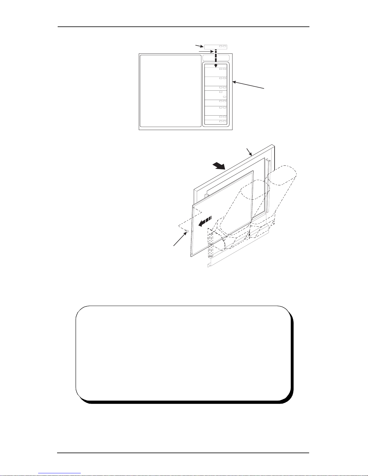
4. Set up the menu
assembly:
a. Swivel the
cup turrets
away from the
door.
b. Remove the
thumb scre ws
as shown,
and slide out
the menu
assembly.
c. Install selec-
tion inser t s as
shown.
5. Reinst all the
menu assembly
in the reverse
order of
assembly.
SELECTION INSERT
INSERT AS SHOWN
VIEW A
VIEW A
DOOR
DISPLAY
ASSEMBLY
6. Load the coin
SLIDE
mechanism:
a. Open the cab-
inet door and
the monetary
THUMB
SCREW
door.
b. Insert coins
into the i r
respective tubes until each tube has been filled.
c. Inspect the tubes for shi ngled coins and correct i f necessary.
BRAND NAME LABELS FOR COLD DRINK SELECTIONS
ARE AV AILABLE FROM THE FOLLOWING SOURCES:
National Beverage Screen Printers
609 East Main Street
Williston, SC 29853-5272
Outside South Carolina call: 1-800-325-9021
Inside South Carolina call: 1-803-266-5272
Fax: 1-803- 266-5301
The suggested style is: NBS-57
Size: .81 x 2.62
327p0001
3280020 Page 3 August, 2003
Page 10
Cold Dri n k Center (327/328) Operator’ s Guide
SLIDE
Insta ll Options
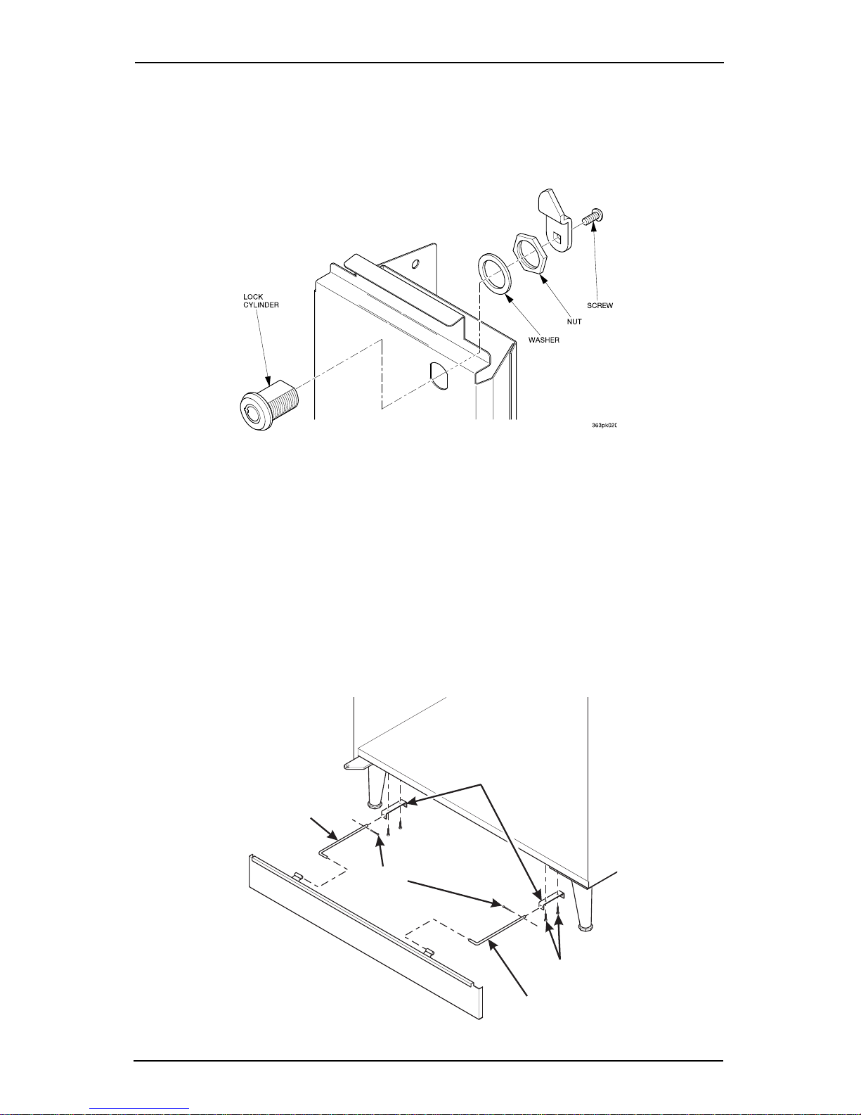
1. Install the coin box lock :
a. Install the lock cylinder, washer, and nut in the order shown.
b. Tighten the nut.
c. Install the lock bar as shown, and secure with the scre w.
2. Mount the base pl ate brackets:
a. Secure a base plate bracket at each of the remai ning pairs of holes with
two of the hex head sc rews.
3. Mount the base plate and slides:
a. Insert the short arm of the slides into the hinged tabs of the base plate.
Position the slide so the notch near the short arm is on the bottom side.
b. Insert the lo ng arms of the slides into th e base plate brackets.
c. Insert a cotter pin through t he hole in the back end of each slide . Secure
the pins in place.
d. Push the base plate toward the merchandiser cabinet. The front tab of
the base plate bracket should seat in the notch in the long arm of the
base plate slides.
BASE PLATE
MOUNTING
LEFT HAND
BASE PLATE
SLIDE
COTTER
PIN
BRACKET
August, 2003 Page 4 3280020
HEX HEAD
SCREW
RIGHT HAND
BASE PLATE
Page 11
Cold Drink Cente r (327/ 328 ) Op er ato r’s Gu ide
NOTE
The mountin g bracke t s are sub jec t to d amage when moving t he
machine with a fork lift. Remove the brackets prior to moving
the machine with a for k li ft to prevent damage.
4. Install the water filter car tridge:
IF YOUR MERCHANDISER HAS THE WA TER FI LTER OPTION, I T CANNOT BE
OPERATED WITHOUT A PROPERLY INSTALLED WATER FILTER CAR
TRIDGE.
NOTE
Check the water filter installation record. There is a place to
write the vend number on the cartridge. Local conditions may
require more frequent replacement.
a. Your filter cartridge i s shipped inside the waste p ail. Locate it and
remove the wrapping.
b. Install the filter in accordance with the appropr iate procedure:
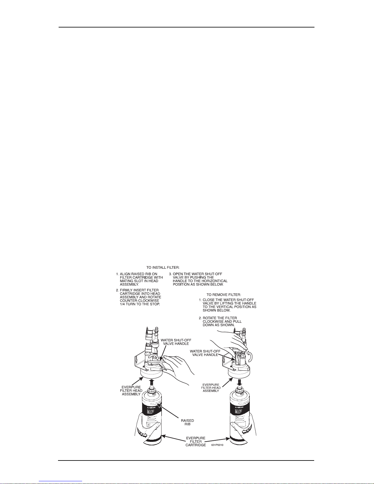
EVERPURE W ATER FILTER INSTALLATION
Check the water filter installation record. There is a place to write the vend number on the cartri dge. The cartridge is ef fective for a maximum of 10,000 18 oz.
vends, 11,000 16 oz. vends, 15,000 12 oz. vends, or 20,000 9 oz. vends. Local
conditions may require more frequent replacement.
-
a. Your filter cartridge i s shipped inside the waste p ail. Locate it and
remove the wrapping.
b. Gain access to the water filter head assembly, located at the cabinet
back wall abov e the wat er bath.
c. Install the filt er as shown.
3280020 Page 5 August, 2003
Page 12
Cold Dri n k Center (327/328) Operator’ s Guide
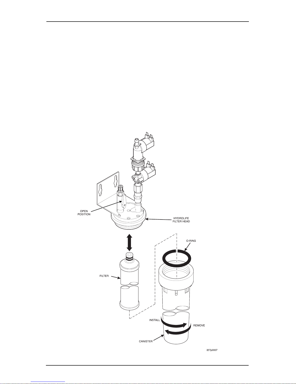
HYDROLIFE FILTER INSTALLATION
a. Place the fil ter inside the canister. Be sure the o-ring is seated in the
caniste r just below the threads.
b. Screw the canister and filter assemb ly onto the filter head unt il it com es
to a stop.
c. Open the water valve on the inlet line by rotating the handl e to the verti-
cal position as shown.
HYDROLIFE FILTER REMOVAL
a. Close the v alve on the inlet line by rotating the handle into t he horizonta l
position as shown.
b. Relieve water pressure by performing two or three water throws (See
"Test Throw Still Water" on p age 64).
c. Unscrew the filter and canister assembly from the filter head. Remove
the filter from the canister.
August, 2003 Page 6 3280020
Page 13

Cold Drink Cente r (327/ 328 ) Op er ato r’s Gu ide
Get The M achine R eady To Vend Drinks
1. Fill the water bath:
a. Open the convenience valve.
b. Fill the water bath level with the carbonator top, or until water runs out
the water bath overflow tube.
2. Load and set up cold drink products:
Bag-in-box machines:
a. Place the bag-in-box containers on the left hand si de of t he cabinet with
the fitti ngs facing up.
b. Connect the syr up lines to the bag-in-box container s. Note that the
syrup lines are mar ked wit h the number s 1 thro ugh 8. These corres pond
to the pumps, which provide syrup for selections A through H, respec
tively. Make sure the bag-in-box containers you have installed agree
with these markings.
c. Place connectors inside box.
Syrup tank machines:
a. Load syrup int o the tanks.
b. Insert the syrup dip tubes into the tanks and place the lids on the tanks.
Note that the syrup lines are marked with the numbers 1 through 8.
These correspond to the pumps, which provide syrup for sel ections A
through H, respec tively. Make sure the syrup tanks you have installed
agree with these markings.
-
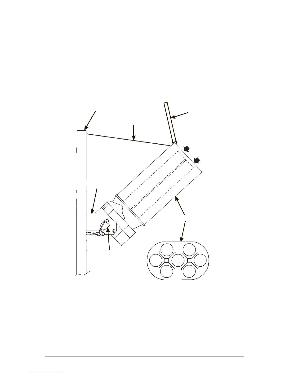
Load the cup mechanism:
NOTE
Use cups that have been designed for use in a cold beverage
vending machine. Do NOT use cups made of clear
(transparent) material.
For single cup size machines, the sa me size cups must be loaded in turr ets 1A,
1B, 2A, and 2B. For dual cup size ma chines, small cups are loaded in turret s 1A
and 1B; large size cups are loaded in turrets 2A and 2B. The size of cup you
load, and its location, must agree with the available cup mechanisms and
the cup size that you sel ect duri ng progra mming. Refer t o the progr amming
section (an d the section on cup mechanisms) for more information.
a. Support the cup mec hanism in the upright posi tion.
b. Push the latch forward to release the cup mechanism. Continue to sup-
port the cup mecha nism while you lower it into t he loading position.
c. Remove the turret cover.
3280020 Page 7 August, 2003
Page 14
Cold Dri n k Center (327/328) Operator’ s Guide
OBSERVE PROPER HYGIENE - DO NOT TOUCH THE CUPS!
d. Open the bottom of the wrapper on a stack of cups.
e. Insert the wrapped cups into the turret and pull the wrapper out.
DO NOT FILL CUPS ABOVE THE LEVEL MARKED ON THE
OUTSIDE OF THE CUP TURRETS OR ABOVE THE “FILL
LINE” LABEL INSIDE EACH TURRET, OR MOTOR JAMS
WILL OCCUR.
USE ONLY THE SAME SIZE AND BRAND OF CUPS IN
EACH TURRET; DO NOT INTERMIX!
f. Replace the turret cover after the turrets have been loaded.
g. Be sure the cup mechanism is locked into th e upright position.
CABINET
DOOR
RETAINING
STRAP
LID
LOAD CUPS
HERE
CUP MECH
MOUNTING
BRACKET
LATCH
CUP TURRET
CUPS
TOP VIEW
August, 2003 Page 8 3280020
Page 15
Cold Drink Cente r (327/ 328 ) Op er ato r’s Gu ide
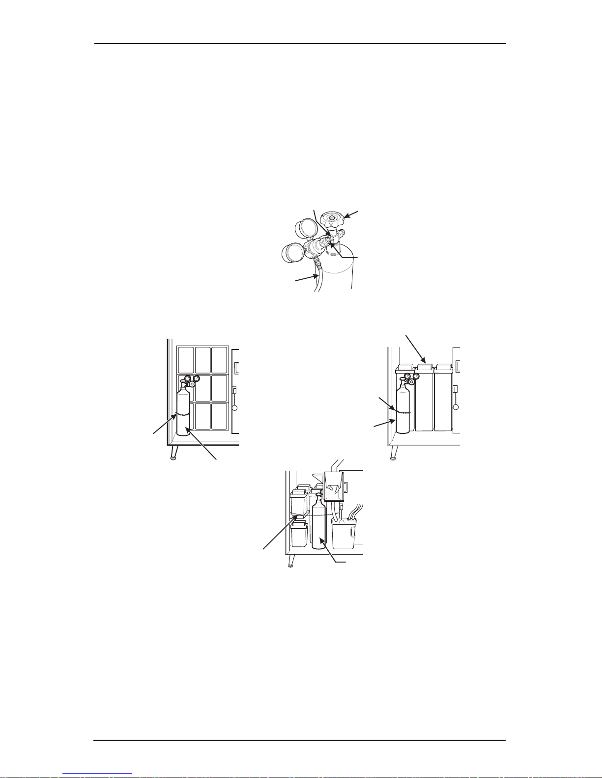
Set up the CO2 tank:
NOTE
A full CO2 tank can be da ngerous if it is drop ped or mishandl ed. Handle with care
and keep the tank lid in place until the tank is properly secured in the
merchandiser.
a. Place the power switch in the OFF position.
b. Install a full CO2 tank on the merchandiser as shown. Secure the CO2
tank wi th the retaining chain. (N ote the var ious retaining chain configura
tions.)
ADJUSTMENT
SCREW
CO HOSE
2
(REAR OF TANK SHOWN)
CO CYLINDER
2
VALV E
ADJUSTMENT
LOCK NUT
-
SYRUP TANKS
RETAINING
CHAIN
CO CYLINDER
2
RETAINING
CHAIN
CO CYLINDER
2
LOCATION 1
LOCATION 1
˜
RETAINING
CHAIN
LOCATION 2
CO CYLINDER
2
327p0008
c. Remove the CO2 tank lid. Briefly open and close the CO2 cylinder val ve
to blow out any forei gn m atter.
d. Locate the CO2 regulator and flat plastic washer (in a box), and the
tapered plastic washer (in plastic bag).
e. Connect t he CO 2 hose from the secondary regulator tee f it ting to the reg-
ulator. Firmly tighten the fitting.
3280020 Page 9 August, 2003
Page 16
Cold Dri n k Center (327/328) Operator’ s Guide
NOTE
Not using a wrench on the tank si de may damage the CO2 t ank,
result ing in personal injury.
f. Using two wrenches, tighten the line to the regulator.
g. Insert the flat washer into the regulator nut.
h. Using two wrenc hes, connect the regulat or to the tank outlet and tighten
in place.
i. Open CO2 tank valve.
j. Adjust the CO2 regulator so that the gauge reads 60 PSI (4.10 bar).
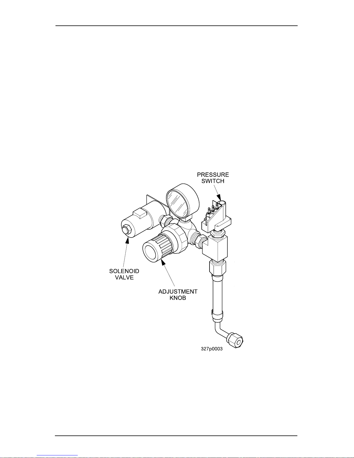
k. The secondary regulator is located behind the monetary panel on the
right side of the cabinet. Adjust the secondary regulator to 40 PSI ( 2.76
bar).
l. Lock the adjustment screw in pl ace.
m. Remove the water bath cover and actuate the pressure relief valve
located on top of the carbonator tank for 3 to 5 seconds.
n. Check for gas le aks along the CO2 line.
August, 2003 Page 10 3280020
Page 17
Cold Drink Cente r (327/ 328 ) Op er ato r’s Gu ide
W
a
s
p
b
t
w
p
t
p
a
d
P
a
o
h
t
i
Is the ratio of syrup to water in a cold drink
BRIX
1. Prime the Syrup System:
Before trying to brix the machine: Operate each syrup val ve (increase flow)
to flush any air or water out of the tubing, pump, or syrup syst em. This resid
ual air and water i s left in the system from factory leak testing and m achine
setup. If air passes through the syrup valve, syrup cannot, and the drink will
be weak.
a. Place a cup in the cup delivery compartment.
b. Perform a syrup test throw . Refer to "Set Up A Drink" on page 36.
Measure the amount of syrup you get.
c. Repeat step b until 1.7 oz (50 ml) of syrup (the proper amount of syrup
for the 12 oz cup) is di spensed.
d. Repeat steps a through c for all the remaining selections in the machine.
e. Remove and discard the cup.
mach in e . Als o , to BRIX the machine is to set
up that ratio.
-
2. Test for Gas Leaks
Now that the pumps are primed, they will not pulse until syrup is called fo r.
Test the lines for gas leaks as follows:
a. Close the CO2 cylinder valve.
b. Observe the hi gh pressure gauge. If the read ing on the gauge
decreases, there is a leak in the system.
c. Locate the source of the leak and r epair it.
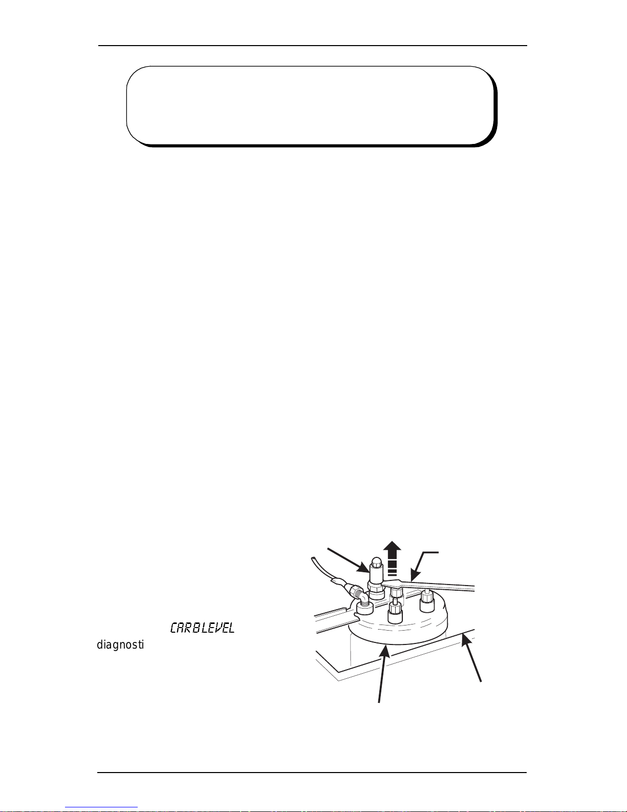
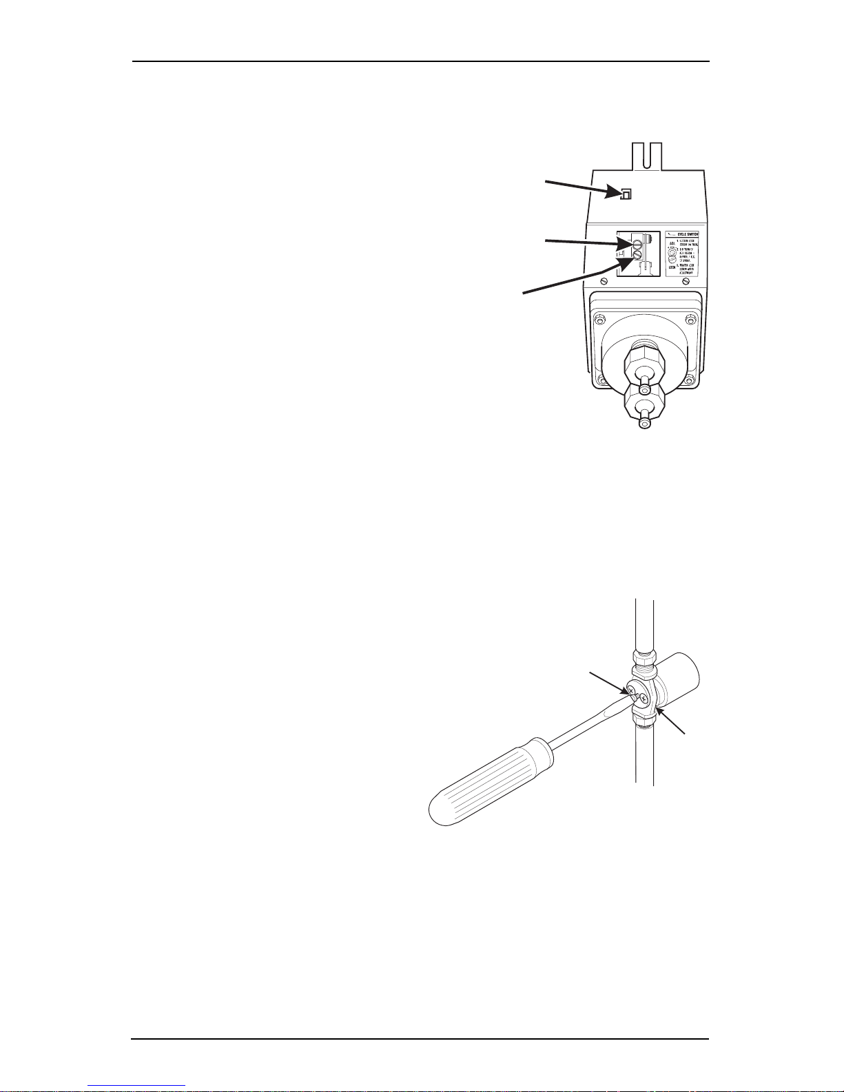
3. Purge the Carbonator of Air
hen a merchandiser is first put into servi ce, air may be present in the carbontor. This air will not mix with the water, nor will i t be absorbed into the water. A
ressure builds up in the carbonator, the air will be trap ped in the top of the caronator and will prevent
he carbonator from filling
ith water. The water
ump wil l no lo nger be ab le
o pump against this high
ressure , and i t will stop
nd di sp lay a
iagnostic message.
urge the carbonator of
ny trapped air by lif t ing up
n the pressu re rel ief val ve
andle as shown. Once
his condition is corrected,
t will not happen again as long as the merchandiser is properly serviced.
3280020 Page 11 August, 2003
`^o_=ibsbi
RELIEF VALVE
CARBONATOR
SCREWDRIVER
WATER BATH
316P0103
Page 18
Cold Dri n k Center (327/328) Operator’ s Guide
Adjustments and Minor Maintenance
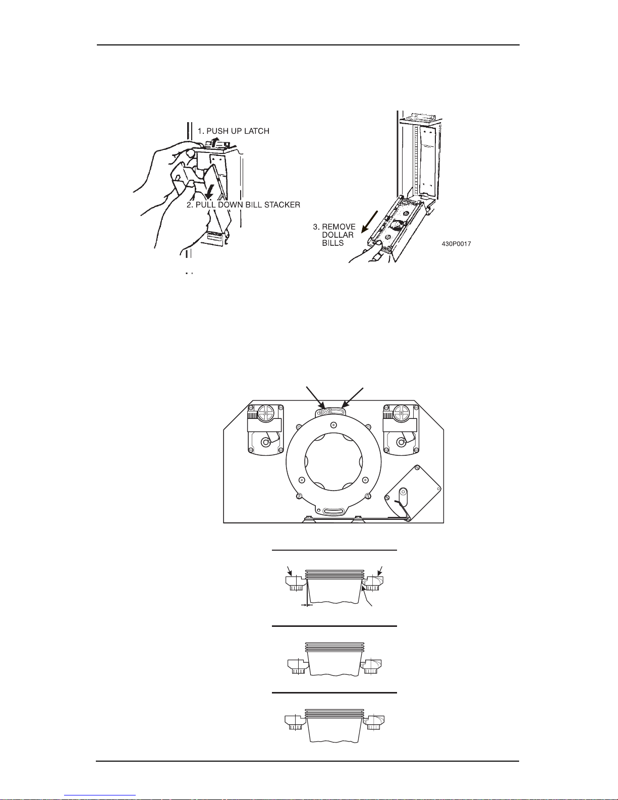
1. Em p ty in g the b ill s tac k e r:
2. Cup mechanism adjustment.
a. Place seven cups in the cup ring.
b. Observe the cl earance as shown in view B.
c. If necessary adjust by firs t l oosening the adjustm ent arm screw (view A).
d. Move adjustment arm until correct clearance is achi eved.
e. Hold adjustm ent arm in place and tighten adjustment arm screw.
LOOSEN SCREW
MOVE ARM
ADJUSTMENT
ARM
View A
View B
VIEW FROM BENEATH
CUP
CAM
CORRECT
ADJUSTMENT
This clearance is just
large enough to allow
cup ejection
ADJUSTED
TOO TIGHT
ADJUSTED
TOO LOOSE
CUP
CAM
This side is snug
against cam
327p0015
August, 2003 Page 12 3280020
Page 19
Cold Drink Cente r (327/ 328 ) Op er ato r’s Gu ide
WATER
C
N
G
SCREW
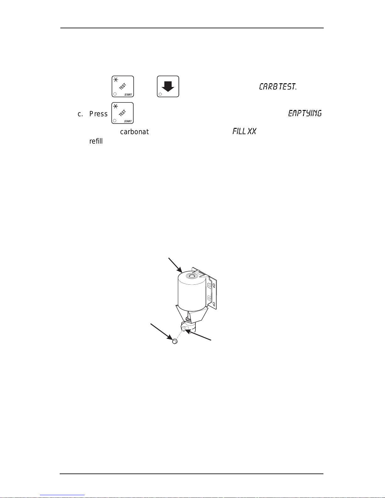
3. Testing the water pump flow
The water pump shoul d require between 13 and 21 seco nds to completely refi ll
the carbonat or. To chec k the water flow, proceed as follows:
a. Place a cup in the cup station and make sure the waste pail is in place.
b. Press , then unt il the display shows:
`^o_=qbpq
c. Press . The water pump start s, and the di splay shows
while the carbonator dispenses, then shows
cfii=uu
as the carbonat or
refills.
d. After adjusting the flow, repeat step c until the desired time is achieved.
4. Adjusting the water pump flow:
a. Remove the cap nut to ex pose the adjustment scr ew.
b. Turn the adjustment screw:
CLOCKWISE to decrease refill time.
COUNTERCLOCKWISE to increa s e re fi ll time.
NOTE
Failure to replace the cap nut will cause the water pump to leak.
c. Replace the cap nut.
PUMP
.
bjmqvfkd=
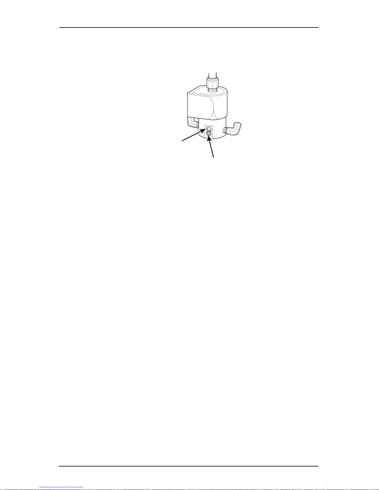
5. Adjusting the water valve:
The water valves are located under the water bath cover.
To prevent personal injury, only turn the adjusting screw when
making adj ustm ents. DO NOT loos en or remove t he li mit scr ew
located above the adjusting screw.
See "Set Up A Drink" on page 36, for the procedure and t able
for set ti ng th ro w s .
3280020 Page 13 August, 2003
AP
UT
ADJUSTIN
NOTE
NOTE
Page 20
Cold Dri n k Center (327/328) Operator’ s Guide
(
ADJUSTING SCREW
a. Rotate the adjusting screw 1/8 tur n:
CLOCKWISE to decrease water throw.
COUNTERCLOCKWISE to incre a s e wa te r th ro w.
b. Repeat the testi ng steps until the water throw is as desired.
LIMIT SCREW
SEE WARNING)
6. Testing the syrup throw:
a. Place a graduat ed fl ask in the cup station.
b. Re fe r to "Set Up A Drink" on page 36, for infor m a ti on on h ow to set
your syrup and perform test throws.
c. Test throw syrup and compare the volume of syrup to the suggested vol-
ume in the table for the cup size being vended.
d. If necessary , adjust the syrup valve to obtain the proper volume.
e. Repeat steps c and d for all selections.
NOTE
Softwar e ti m es do not control the output volume of diaphragm
pumps; they simply start the motor . The output volume is
controlled with a mechanical adjustment in the pump.
August, 2003 Page 14 3280020
Page 21
Cold Drink Cente r (327/ 328 ) Op er ato r’s Gu ide
E
7. Adjusting the Syrup Throw (DIAPHRAGM PUMP):
a. Locate the adjusting block within the syrup pum p. Momentarily activat e
the prime switch to put the adjusting block into clear view.
NOTE
When adjusti ng the crank
PRIMING
SWITCH
arm adjuster screw, loosen
the limit scr ew ¼ turn only.
Loosening t he li m it screw
ADJUSTING
SCREW
more than ¼ turn may allow
the adjuster screw to shift
when the limit scr ew is
LOCK
SCREW
tightened. This will re sult in
an inaccurate adjustment.
b. Loosen the lim it screw ¼ turn, then turn the adj uster
screw:
CLOCKWISE to decr eas e the sy ru p th ro w.
COUNTERCLOCKWISE to increase the syrup throw.
c. Tighten the limit screw .
d. Repeat the test and adj ustment procedur e until the syrup throw is as
desired.
e. Repeat the above steps for each syrup pump.
8. Adjusting the Syrup Throw (CO
2 PUMP)
a. Turn the adjustment screw:
CLOCKWISE to decrease the volume.
COUNTERCLOCKWISE to
increase the volume.
b. Repeat step a for each pum p.
ADJUSTING
SCREW
VALV
3280020 Page 15 August, 2003
Page 22

Cold Dri n k Center (327/328) Operator’ s Guide
WATER LEVEL
W
T
BUSHING
FLOAT ASSEMBLY
9. Setting the icemaker water level:
A proper level should be maintained wi thin the icemaker. To determine the
water le vel, a label is located on the ic em aker that indicates the prop er l evel
in the melt-down tube. The icemaker water level is dependent upon the
feeder cup wat er l evel.
a. Se t th e M AIN S W I T C H to th e OFF (down) position.
b. Remove the water feeder cup cover.
c. Adjust the float shaft bushing:
UP - to raise the water level.
DOWN - to lower the water level.
d. Replace the water feeder cup cover.
e. Check the new water level:
• Set the MAIN SWITCH to the ON (up) position.
•Press , then until the display shows
•Press to dispense still water; press again to stop.
•Press . The feeder cup will refill after you leave the carbonator test.
When the feeder cup is full, press to return to
• When the water flow stops, check the water level in the melt-down tube.
`^o_=qbpq
`^o_=qbpq
.
.
f. Repeat steps a through e until the water level is correct.
SWITCH ACTUATOR
˜
ATER FEEDER
FLOAT SHAFT
1¼
August, 2003 Page 16 3280020
WATER FEEDER
FLOAT SHAF
Page 23
Cold Drink Cente r (327/ 328 ) Op er ato r’s Gu ide
Programming The Cold Drink Center
Getting Around
Getting around the Cold Drink Center software is pretty easy once you know the
feature s that are avai lable to you, and how to use them. The thr ee main par ts you
will use are the SER VICE KEYPAD, the SELECTION SWITCH PANEL, and the
DISPLAY.
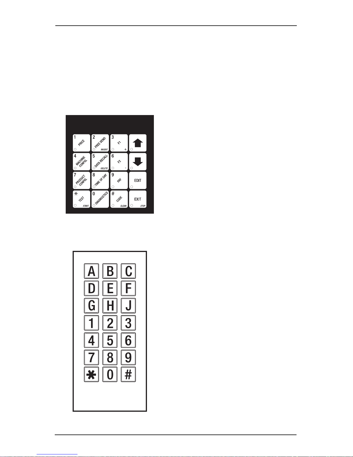
The Service Keypad
For most of your programming jobs,
you will be using t he service keypad,
conveniently located on the monet ary
panel. The service keypad has 16
keys. The three columns on the left
are the MODE keys. The right hand
column contains the MOVEMENT
keys.
he Selection Switch Panel
The selection switch panel is also
located on the monetary panel. Unlike
the service keypad, it is accessible
when the cabine t door is closed.
These are the keys the customer will
use to make select ions. You can also
use these keys during programming
procedures.
3280020 Page 17 August, 2003
Page 24
Cold Dri n k Center (327/328) Operator’ s Guide
T
Y
e
P
e
y
g
s
le,
er
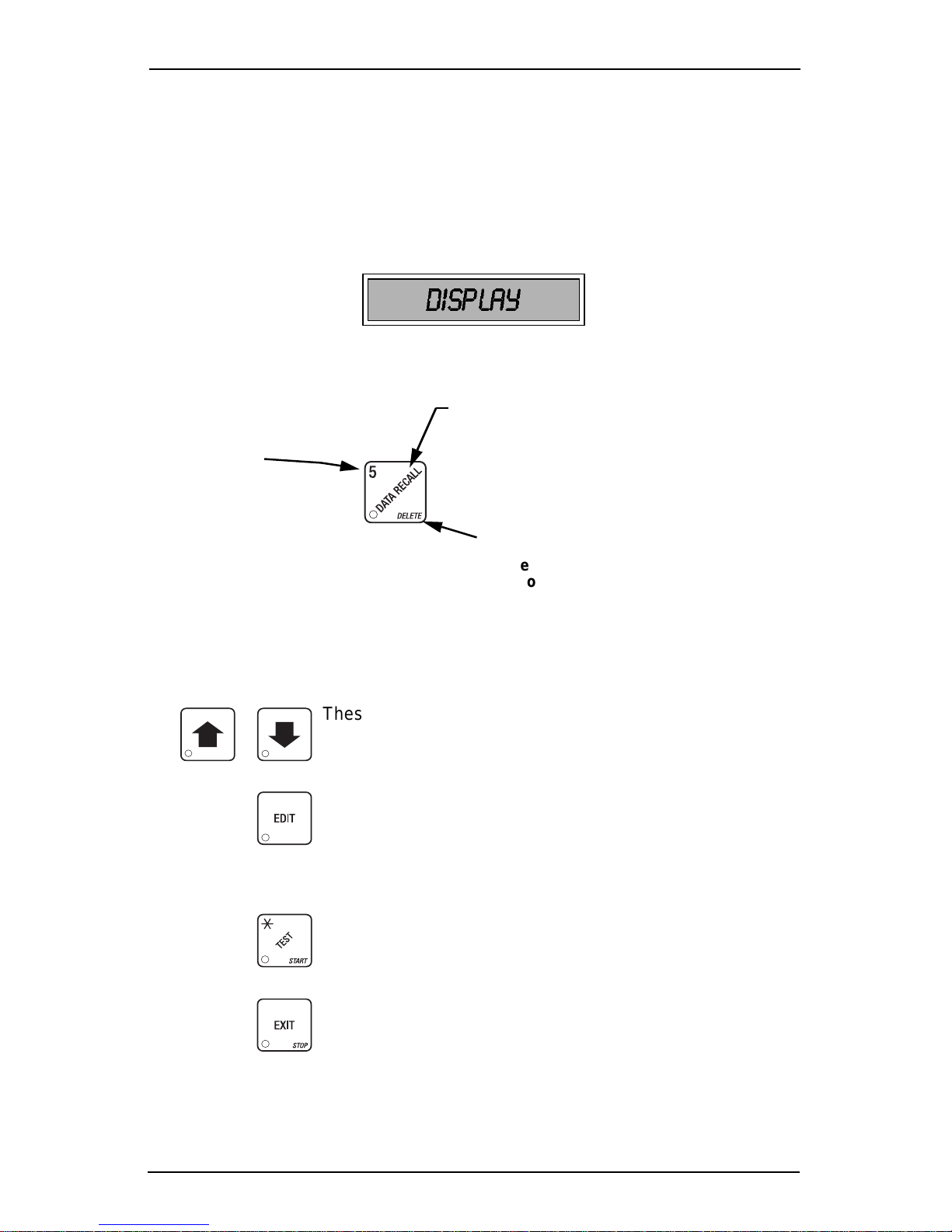
The Displays
The 10-charac ter dis play perfor ms two fun ctions , and is referr ed to in this book as
"the display":
• It shows the cust omer 's sel ecti on and how m uch cr edi t is in t he mac hine, as
well as the ready, service, and time of day messages.
• It provides information and feedback to the service per son during maintenance.
DISPLAY
The Function Keys
The keys on the control panel can be used for up to three things:
THE PRIMARY PURPOSE
This is the main job of the key. From the standb
messag e, it will allo w yo u to enter a pro g rammin
HE NUMBER
ou might be asked to
nter a numerical value.
ressing this key will
nter a "5".
mode. In this example, you can view stored sale
data.
THE SECONDARY PURPOSE
This is the key's "second job". For examp
this key can be used to delete a charact
when yo u are edi ting cu sto m m e ssages.
Other Keys
The MOVEMENT keys on the control pan el let you move i nside a mode, and back
and forth between modes.
August, 2003 Page 18 3280020
These keys are your " legs", which let you move up and
down the list of ta sks. They let you continue from one step
to the next in programming procedures.
This is your "activate" or "choose" key. It "opens a door" to
additional information and lets you begin a programming
task once you are insi de of a mode. Sometimes, it is used
as a toggle switch to show you your choices during a programming task.
This key can be used before running a function, or to
choose “ALL” in a multiple selection.
This is your "end" key. Pressing it one or more times will
move you back to the start of the mode, or all the way back
to the standby message.
Page 25
Cold Drink Cente r (327/ 328 ) Op er ato r’s Gu ide
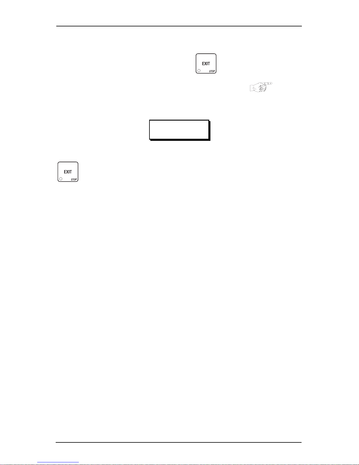
Some Conventions:
All programming procedures assume that you are starting with the standby mes-
sage showing i n the di splay. If not, just press until you get there.
Each progra mmi ng procedure is highlighted by a poi nting hand: so it will
stand out .
Definiti ons and helpful information will appear i n shadow boxes:
Helpful Hint
When you see the word CONTINUE at the end of a function, it means to press
until you return to the standby message.
3280020 Page 19 August, 2003
Page 26

Cold Dri n k Center (327/328) Operator’ s Guide
Control Panel Switch Functions Explained
Press this button to put your machine into the Price Setting mode.
You can see max imum and m ini m um mac hine prices, and change
prices for ent ire machine, entir e tray, or individua l sel ection.
Press this button to set up how the Free V end mode will operate.
Press this button to view the software version number, machine and
accessory configuration, and active selection status.
Press this button to:
• Select display language
• Select coin m echanism and
options
• Select bill validator and opti ons
Press this button to:
• View tot al sales and vends by
whole machine, selection, or
drink si ze
Press this button to:
• Download data into your portable data collection device (PDCD),
OR
• Set printer baud rate, depending upon which device you are using
Press this button to:
• Set machine configuration
• Set which selections are active
• Select card reader and
options
• Select monetary options
• Set winner feature
• Set mug discount option
• Clear resettable data
• View or set machine I D
Press this button to:
• Set time of day
• Set day, month, year
• Select di splay messages
• Edit messages
Press this button to pay one or more coins from the coin mechanism .
Press this button to see any fault or con dit ion that may place the
machine out of service
Press this button to:
• Perform TEST VENDS
• Test machine functions
Press this button to:
• Enter the SUPERVISOR mode
• Change the SUPERVI SOR
access code
• Set message scrolling speed
• Set up time of day intervals
for inhibit , freevend, and discount vending
• Tes t di splays
• Lock and unlock access to
functions
• Set free vend code
August, 2003 Page 20 3280020
Page 27

Cold Drink Cente r (327/ 328 ) Op er ato r’s Gu ide
SureVend™
SureVend™ ensures that a cup is always available in the cup station before any
money is coll ected or product deli vered. The sensing system is a beam of i nfra
red light across the cup station that is brok en by the cup when it falls into position.
The SureVend™ software m onitors the cup stati on sensor during the time the cup
ring is cycled and for three seconds afterward. If a cup is not detected, the soft
ware will first determine if a second cu p ri ng with the same size cups exists and
will then try t o drop a c up f rom the s econd ring. If t he second ring al so fail s to dr op
a cup or is not usabl e, the so ftwa re will repeat the atte mpt from th e first cup ring to
attempt to cl ear any jams i n the cup del ivery area . Each ring will be tr ied up to two
times. If a cup is st il l not detected by the inf rared sensor then sev eral things hap
pen:
• Any ring that failed twice in a row is placed temporarily out-of-service for a
length of time t hat is determined by the user,
• The customer' s credit is either restored for another vend att em pt or is
retu rned auto m atic a l ly,
-
-
-
• Three beeps sound and the message
another si ze cup ring is available), or the message
the event that no other cups are available. The customer may always get a
refund by pre ssing the coin return but ton.
NOTE
INSERT MUG
message if desired (se e
Special rules exist to protect both the customer and the operator from loss. First
and foremost, the customer is protected because no drin k is spoiled nor money
lost becau se a cup fails to fall to the cup st ation. The customer is gi ven every
chance to get hi s ori ginal choice of cup size by trying at least twice per ring to
eject a cup. If two rings are availabl e with the same cup si ze, the system will alter
nately try to vend a cup from each ring until the cup is delivered or both rings are
placed out-of-service.
The operator is protect ed by the anti-jack pot progr am of the syst em. It is conc eivable that a customer could prevent cups from reaching the sensing area of the
cup station in order to steal the cups and then get a refund for the vend. Under
the SureVend™ Anti-Jackpot system, the operator can lose no more than two
cups in a row per ring. Then that ring is temporarily placed out-of-service both to
protect the cu stome r and t o discou rag e thef t. T he amoun t o f time that the cup r ing
is out-of-service is program ma ble from 0 to 99 minutes. After th e ti me has
elapsed , the cup ri ng will ret urn to ser vice but the count of the two fail ures is ke pt.
If the previous problem was theft, then the next vend attempt from that ring will be
successful and the count of the two previous failures will be erased. If the prob
lem is an actual system failure, then the third failure will permanently place that
cup ring out of service until a service technician visits the machine.
is the default message. You may customize this
"Edit Custom Message" on page 49
for more information).
SELECT ANOTHER SIZE
IN S ERT M UG
flashes (if
flashes in
-
-
3280020 Page 21 August, 2003
Page 28

Cold Dri n k Center (327/328) Operator’ s Guide
An induced SureVend™ fai lure cannot cause an alternate vend from a selecte d
small cup to a large cup at the small cup price. This protects the operator from
customers trying to get large cup dr inks at a small cup pr ice . (SureV end ™ will not
automatically switch to a different cup size in mid-vend because it cannot be
ensured that correct change will be returned for the new price.)
To turn Sure Vend™ off, see "T urn SureVend™ On or Off" on p age 42.
The Supervisor Mode
The supervisor is allowed to do things that a normal user cannot, like controlling
access to cer tain modes. The supervi sor can lock out any of the programming
modes to any one who does not hav e the r igh t "ke y". On ce a super visor ent ers t he
proper code, he or she wi ll be able to:
• Change the supervisor access code
• Lock out any or al l of the service keypad mode s
• Set whether data is cleared with or after being downloaded into a
portable data collec ti on device
• Grant or deny access to data items during DATA RECALL
• Modify the machine configurat ion
August, 2003 Page 22 3280020
Page 29

Cold Drink Cente r (327/ 328 ) Op er ato r’s Gu ide
Programming Procedures
GAIN ACCESS TO THE SUPERVISOR MODE
1. Press . The display shows:
digit supervisor code within 6 seconds to gain access.
A new machine has a factory-set supervisor code of 0000.
When you have entered the right code, you will hear two beeps and see
UNLOCKED
2. CONTINUE.
in the display.
ENTER CODE
NOTE
. You must enter the four-
ENTER A NEW SUPERVISOR CODE
1. Follow the steps in "Gain Access To The Supervi sor M ode" on page 23.
2. Press . The display shows
current supervisor code. Use the number keys to enter a new code.
If you enter a new code, be sure to keep a written record of it.
There is no other way to access the SUPERVISOR mode.
SUPER XXXX
NOTE
. The X's represent the
3. CONTINUE.
ENTER A FREEVEND CODE
(Supervisor Mode Only)
1. Follow the steps in "Gain Access To The Supervi sor M ode" on page 23.
2. Press , then unt il the display shows
represent the current freevend code. Use the number keys to enter a new
code. If the code is anything other than "0000", it must be entered after the
key lock is turned in order to enable free vends.
3. CONTINUE.
FREE XXXX
. The X's
3280020 Page 23 August, 2003
Page 30

Cold Dri n k Center (327/328) Operator’ s Guide
ENTER A NEW DATA RECALL CODE
(Supervisor Mode Only)
If the proper n on-zero code is ente red, sa les and n on- resett a ble sal es dat a ca n be
viewed without opening the machine’s door.
1. Follow the steps in "Gain Access To The Supervi sor M ode" on page 23
2. Press , then unt il the display shows
represent the currently entered code. Use the number keys to enter a new
code, if desired.
NOTE
A code of 0000 disables this feature.
Usage:
In ready mode, ent er the 4-digit code. When the correct code is entere d, the nonresett able sales total is displayed. Press # to view the total number of vends.
Enter a le tt e r ke y (e x.
and 0 (ex.
show the l arge cup to tal ). Pre ss # to cycle t hr ough the compl ete sel ecti on li st. The
display will remain act ive for 9 second s.
3. CONTINUE.
0B
) to view the sales total for that product , regular size cup (
B
) to view the sales total for that product. Press a letter key
NR XXXX
. The X's
1 B
will
LOCK OR UNLOCK MODE OR PAYOUT KEYS
(Supervisor Mode Only)
1. Follow the steps in "Gain Access To The Supervi sor M ode" on page 23.
2. Press , then unt il the display shows either #
UNLOCKED
maintenance keypad.
3. Press to change bet ween locked and unlocked . When anyone other
than the super visor tries to enter a locked mode, the display shows
EXAMPLES: Press , then to lock the function. Now , non-s upervi-
sors cannot view any sales data. If you want non -supervisors to vi ew data but not
be able to clear dat a, leave the
4. CONTINUE.
. To see if a key is locked or unlocked, press that key on the
key unlocked, but do lock .
NOTE
Mode keys and cannot be locked out:
LOCKED
or #
LOCKED
.
August, 2003 Page 24 3280020
Page 31

Cold Drink Cente r (327/ 328 ) Op er ato r’s Gu ide
SET TALKER MODE
(Supervisor Mode Only)
1. Follow the steps in "Gain Access To The Supervi sor M ode" on page 23.
2. Press , then unt il the display shows
3. Press to turn the talk er opt ion ON or OFF.
NOTE
Talker hardware must be inst alled for this to work.
TALK ON or TALK OFF.
SET PRINTER OR DEX MODE
(Supervisor Mode Only)
1. Follow the steps in "Gain Access To The Supervi sor M ode" on page 23.
2. Press , then unt il the display shows:
PRINTER
DEX ONLY
DEX+CLR
DEX NR
- means that data will be sent directly to a printer,
- data remains in memory after it is downloaded into a portable
data collection device (PDCD),
- resettable data is cleared after it is downloaded into a PDCD.
- a speci al DEX option. All sales data will become non-resettable.
Consult your DEX supplier before choosing this option.
3. Press to change between the three choices.
4. CONTINUE.
3280020 Page 25 August, 2003
Page 32

Cold Dri n k Center (327/328) Operator’ s Guide
SET DEX OPTIONS
1. Follow the steps in "Gain Access To The Supervi sor M ode" on page 23.
2. Press , then until the di splay sho ws one of two reset tabl e bil l
valid a to r tota ls transmitted to th e DE X de v ic e:
CA 304 = N.C.
mat. For exampl e: 200 for two dollars. (Thi s is the default sett ing.)
CA 304 = N.O.
count format. For example: 2 for two dollars.
3. Press to switch between the two choices. Consult your DEX
handheld supplier for the proper settings for your mach ine.
If the bill count is incorrect, the CA304 setting may be wrong. Try another setting.
4. Press until the display shows one of the following two options:
LAST.VND.ON
LAST.VND.OFF
5. Press to switch between the two choices.
- the value of bills in the st acker will be transmitted in a cash for-
- the value of bil ls in the stacker will be transmitted in a dollar
NOTE
- the DEX device will transmit the date and time of the last vend
for each selection.
- the DEX device will NOT transmit the date and tim e of t he last
vend for each selection. (This is the default setting )
6. CONTINUE.
SELECT PRINTER BAUD RATE
(Printer mode only)
BAUD
RATE
1. Press . One of the following is di splayed:
BAUD 1200 BAUD 2400 BAUD 4800 BAUD 9600
2. Press until the correct baud rate for your printer is displayed.
3. CONTINUE.
The speed of data transfer, expres sed in bits per second.
Your printer can receive dat a at a certain rate, and you m ust
tell the machine what that rate is.
August, 2003 Page 26 3280020
Page 33

Cold Drink Cente r (327/ 328 ) Op er ato r’s Gu ide
SELECT DISPLAY LANGUAGE
1. Press . The current LANGUAGE is shown in the display. Press
to choose the desired language. Your choi ces are:
ENGLISH, DEUTSCH, FRANCAIS, ESPANOL, PORTUGUES, SWEDISH, NEDERLANDS
FINNISH
2. CONTINUE.
.
, or
SELECT COIN MECHANISM
1. Press , then press until the current COIN MECHANISM is
shown in t he displ ay. Pr ess to cho ose t he desi red coin m echanis m.
Your choices are:
MDB MECH, DUMB MECH, EXEC MECH
2. Proceed to "Select Monet ary Opt ions" on p age 30, to custo mize y our co in
mechanism choice.
Depending upon your choice of coin mechanisms, some
displays may not appear.
, or
NOTE
NO MECH
3. CONTINUE.
3280020 Page 27 August, 2003
Page 34

Cold Dri n k Center (327/328) Operator’ s Guide
SELECT BILL VALIDATOR AND OPTIONS
1. Press , then press until one of the following is disp layed:
NO DBV
SER.1.2.5.10.20
PULSE DBV
MDB.1.2.5.10.20
MDB.
<*>
BILL SELECTION METHOD:
The standar d $1, $2, $5, $10 and $20 bil ls are enabl ed by pressi ng the 1, 2, 5, 6,
or 7 key(s), respectively, to display which bill(s) will be accepted.
- No bills will be accepted or t here is no bill validator installed
(you can exit the function).
- The serial bill validator is select ed and wil l accept $1, $2,
$5, $10, and $20 bills. Use BILL SELECTION METHOD
below to change the bills that will be a cce p te d .
- The pulse bill vali dator will accept $1 bill s.
- A standard MDB bill valida to r is sele c te d . It wi ll acc e p t $1 ,
$2, $5, $10 and $20 bills. Use BILL SELECTI ON ME THOD
below to change the bills that will be a cce p te d .
- An MDB bill validator t hat accepts non-standard bills or
tokens is conn ected and operating. Press to enter
list of bills. See "Initial Setup Of NonStandard Bill Valida-
tor" on page 29.
1. Press to choose the desired opt ion.
2. CONTINUE.
August, 2003 Page 28 3280020
Page 35

Cold Drink Cente r (327/ 328 ) Op er ato r’s Gu ide
INITIAL SETUP OF NONSTANDARD BILL VALIDATOR
1. Connect the bill validator, and follow the steps in "Selec t B ill Valid a tor and
Options" on p age 28, to sele c t
screens.
MDB.=
<*> will not be an option yet. Exit the bill validator setup by
MDB.1.2.5.10.20
in the bill validator selection
pressing
2. Press , then press until
3. Press .
validator channel 1, the
the validator will accept $1.00 bil ls.
4. Press to toggle the bill acceptance ON or
5. Press and to scroll through the list of other denominati ons
and to set them to ON or
. Bill informati on is now collected from the validator.
MDB.=
<*> displays.
1. 1. 00 O N
will displa y. The firs t nu mb e r (1.) indicates bill
1. 00
is the bill denomination, and ON indicates that
OFF
.
OFF
.
6. Press to move up to the top level scr een.
NOTE
If a denomination does not display in t he scroll list of ava il able
denominati ons, check the binary switch settings for the
validator. If the binary switch for a given denomination is set to
“off ”, it will not display in the li st of denominations.
7. CONTINUE.
3280020 Page 29 August, 2003
Page 36

Cold Dri n k Center (327/328) Operator’ s Guide
SELECT CARD READER AND OPTIONS
1. Press , then press until the current card reader is shown in
the display. You r choi ces are:
NO CARD, DUMB CARD
2. Press to choose the desired card reader .
3. Press until one of the following is displayed (not available if
is selected above):
REVALUE.ON
REVALUE.OFF
4. Press to display the desired choice.
5. CONTINUE.
- Allows credit to be transf err ed onto the card
==J==
Credit cannot be transferred to the card
, or
M DB CAR D
.
SELECT MONETARY OPTIONS
NO CARD
This function lets you:
Set change return cri teria
Set currency acceptance on low
change
Depending on th e coin mech and bill valid ator selected, some options below may
not be available.
1. Press , then press until the display shows
X.XX represents the largest denomination coin or bill that will be changed
without a purchase. Any non-zer o value here will return all esc rowed coins.
(Each coin denomination that th e coin mech has a tube for is called an
ESCROWED coin because it can be returned.) When the coin return but ton
is pressed , all coins insert ed wil l be r eturned provided ther e is a coi n me ch
tube for each of those coins, EXCEPT in the forced vend mode.
Set overbuy options
Set last bill stacking options
Set declining balance
CH ANGE X. X X
.
August, 2003 Page 30 3280020
Page 37

Cold Drink Cente r (327/ 328 ) Op er ato r’s Gu ide
Some examples:
CHANGE 0.00
CHANGE .25
less than .25 denom ination or have a payout tube. Acceptance of a dollar
coin will not cause a Force Vend if the coi n mechani sm has a dollar coin pay
out tube. Otherwise, accepting a dollar coi n or accepting and stacking of a
dollar b ill w ill cause a F o rc e Vend.
CHANGE 1.00
be changed without purchase. All escrowed coins are returned.
Use the keypad to enter a value for the change num ber.
2. Press until one of the fo ll owing is disp la y e d :
ACC
=
<
$$ X.XX
A C C.STK X.XX
- Forced vend; NO change returned with out a purchase.
- Returns change without purchase if all accepted coins are
- Bills and non-escrowed coins less than or equal to $1.00 will
-Accept any bill of value $X.XX or less, r egardless of available
change. Hold the last bill that meets or exceeds maximum
price in escrow . (This setting is normall y used.)
-Accept any bill of value $X.XX or less, regardless of available
change. Immediately stack the last bill.
-
Example: If setting is
ting will im me diately stack the second $1.00 bill in serted.
3. Press to display the desired choice.
4. The value of "X.XX" has two purposes:
a. The value of "X .XX " te lls th e mac h in e ho w big a b ill o r coin to ac c ept
even though the re is not enough change in the coi n mec h to cover all
possible paybacks.
For example, enter 1.00. Therefor e, the machine will t ake a dollar bill or
coin even though there is less than $1.00's worth of change. Entering
5.00 tells the machine to take a fiv e even though there is less tha n
$5.00's worth of change, and so forth.
This coul d cause a customer to be short-changed.
Entering 0.00 means that bills or coins not held in escrow or in a tube will
only be accept ed if there is enough change to cover them.
b. The value of "X.XX" tel ls the machi ne how much the cust omer is allowed
to overbuy a pro duct. The customer will be short-changed when an
overbuy occurs.
ACC.STK 1.00
NOTE
and maximum price is $1.50. This set-
3280020 Page 31 August, 2003
Page 38

Cold Dri n k Center (327/328) Operator’ s Guide
Example:
For a value of $0.25: if there is no change in the machine and the customer
insert s a $1.00 bill, the custom er can purchase a product for $0.75 even
though the change cannot be paid back. The customer will be shortchanged. Normal ly a purchase will not be approved unless all change can
be paid.
Entering 0.00 means that the vend will only be approved when the correct change can be returned (overbuy disabled).
5. Press until the display shows:
USE EXACT CHANGE
when the amount of available change in the coin
LOW.MSG X.XX
. The display will sho w
mechanism falls below the value of "X.XX". Enter a value with the number
keys. For example, if
LOW. MSG 1.00
is displayed, the
USE EXACT CHANGE
message is displ ayed wh en less tha n a doll ar's wor th o f change is in the coi n
mechanism.
DECLINING
BALANC E :
Once credit is established, multiple
vends may occur until the coin
return is pressed.
6. Press until one of the fo ll owing is disp la y e d :
DECLINE.ON
DECLINE.OFF
- More than one vend is allo wed, wi th a decl ining balance.
- A declining balanc e is not all owed.
7. Press to display the desired choice.
8. Press until one of the fo ll owing is disp la y e d :
FAIL=CASH
- If the customer’s primary selection is unavailable, they will be
able to collect a full refund by pressing the change return button.
FAIL=CREDIT
- If the customer’s pri ma ry sel e ction is unavail able, they will be
able to make an alternate selection, but not get a full refund.
This option only available if SureVend is ON.
9. CONTINUE.
August, 2003 Page 32 3280020
NOTE:
Page 39

Cold Drink Cente r (327/ 328 ) Op er ato r’s Gu ide
SET UP WINNER MODE
At preselected intervals, a cust om er may receive a
WINNER
1. Press , then press until one of the following is displayed:
refund for a selection. You can select the interval and
qualif yi ng selectio ns .
WINNER OFF
WIN XXX
2. Press to display the desired choice.
If you sele cted
3. The displ ay shows
occur per each winner vend. For example, an interval number of 50 means
that a winner can happen any one time during the next 50 vends. Using the
number keys, ent er an interval number bet ween 10 and 9999.
4. Press . The display shows
represent which s elect ions ar e allo wed winner s. Pres s the appr opr iate let ter
key to enable a selection, press the key again to disable it. For example,
pressin g A, C, and E will cau se the display to look like t his:
=
A
- C - E - - - , meaning that all A, C, and E selections can have a winner.
*.
ADVANCED OPTIONS:
Winner function is disabled.
Winners are allowed at certain interval s, represented by "XXX".
WINNER OFF
WIN XXX
, you can exit the funct ion.
. XXX represents the number of vends that must
==
- - - - - - - -
*
=
. The dashes in the display
•Press to enable all selec ti ons.
•Press to deactivate all selections.
•Press 0 or 1 to set winner selections by cup size.
If displaying WINNER by selection, press once to
redispla y wildcard (
3280020 Page 33 August, 2003
NOTE
=
.
*
ABC
....) s e lecti o n s.
Page 40

Cold Dri n k Center (327/328) Operator’ s Guide
AN EXAM P L E . . .
You want to enable winners on all selections except E and F. Do the following:
a. Press . The let ters
the dashes.
b. Press "E" and "F". The letters
dashes.
This is a two-part scre en. Press to display selections
5. CONTINUE.
A
through J appear in the display instead of
E
and
F
in the display are replaced by
NOTE
Y Z _ _ _ 8 9
*.
.
SET UP MUG DISCOUNT
You can establish a disco unt for customers who use thei r own mug.
1. Press , then press until the disp lay sho ws
example shows the existing disco unt amount is zero.
MUG DSC .00
. This
2. Enter a discount amount. This will be in cents, for example pr ess or
5 to enter a discount amo unt of 5 cents.
3. CONTINUE.
DISABLE SELECTIONS IN THE MERCHANDISER
1. Press , then press until the display shows something like:
LK. ABCDEF
not available for vending. An available selection has its letter replaced by a
blank space.
2. Press the appropriate letter to togg le the display on or off.
Press to lock all selections ; press to unlock all
. This display means that a ll regular size selections (A - F) are
NOTE
selections. Press to display the second screen.
3. CONTINUE.
August, 2003 Page 34 3280020
Page 41

Cold Drink Cente r (327/ 328 ) Op er ato r’s Gu ide
SET UP CUP SIZES
Make sure the cup si zes you select agree with t he cups you have actually loaded
during setup.
1. Press then until the display shows
current ly sel ected dr ink si ze for t he cu ps in t urret 2 (normal ly la rge cup s), "Y"
is the c urrent ly sel ected drink size f or the cup s in t urret s 1A and 1B ( normal ly
regular cups).
2. Press to cycle throu gh the avai labl e #1 cup ri ng sizes ; pres s
to cycle th rough the available #2 cup ring sizes.
3. Any changes made to the cup sizes must be "locked in". There are two
ways to d o this:
a. If you are keeping some cup sizes the same, or putting the cups in di ffer-
ent cup ring s, pr ess and hold . The display momentarily shows
CLEARING
old throw times t o the new cup ring, if possible.
b. If you are loading all different size cups, or want to load all new default
, two beeps sound, then shows
FINISHED
X OZ Y
. This will reassi gn the
. "X" is the
times, press and hold
CLEARING
tory defa ult times for all cup sizes, clearing any cust om throw times you
have established. (See
on page 37.)
Machines with diaphragm pumps (see "Configure Pump
4. CONTINUE.
. The display momentarily shows
, two beeps sound, then shows
"Factory Default Throw Times and Volumes"
NOTE
Type" on p age 39) can only vend one cup size.
FINISHED
. This will reload the fac-
3280020 Page 35 August, 2003
Page 42

Cold Dri n k Center (327/328) Operator’ s Guide
SET UP A DRINK
Be sure that the cup sizes you set in "Set Up Cup Sizes" on page 35, agree with
the cup si zes ac tua lly in y our machi ne. Al l pr ocedu res for se tt ing up the dri nk s are
similar, so this exam ple will demonstrate how to set up the A selection, regular
size drink.
1. Press , then press until the display shows
star (
size of the selection.
2. Press A. (If you were set ting up the A selection for the large size drink , you
would press 1 first, then A.) The display shows some thi ng similar to:
CLD. A 12.00
A selection is 12.00 seconds. Enter a new time if des ir ed.
3. Press . The display shows
currently set carbonated water throw time for the A selection is 12.00
seconds. En ter a new t ime if desir ed. A val ue of .00 will loc k out car bona tion
for the selection.
4. Pressing after each display will cause the following scr eens to
appear:
) represen ts the selection (A , B, et c.). The dash (-) represents the
*
. This means that the currently set still water throw time for the
CRB. A 12.00
. This means that the
SETUP --
*. The
SRP. A
PCT. A
ICE. A
ICE. A+
OPTIONS:
a. At any of the prec eding di sp lays, you can pr ess to test throw that
b. At any of the preceding displays, you can press * or # (on the selectio n
View and change the settings for syrup
View and c hange the set tings for per cent age of carbona tion ( 0-100) .
A value of 100 will lock out non-carbonation for the selection.
View and change the settings for ice throw time
View and change the settings for extra ice throw time
item.
switch panel) to step through a li st of that item's throw tim es for other
selections where that item is act ive. For example, pressing # at the
CLD. A
display will show the throw time f or either
ing on how the drink si ze s are set up) . This is a handy way to move from
one selection to another without going to the
NOTE
If you try to set up a selection that is not configu red, the
screen w ill re ma in in the d is pl a y.
CLD. 1A
SETUP
or
CLD. B
screen first.
SETUP
(depend-
August, 2003 Page 36 3280020
Page 43

Cold Drink Cente r (327/ 328 ) Op er ato r’s Gu ide
Special Selections:
Ice and Cup 8-4 (small cup)
1-8-4 (large cup)
Carbonated Water 9-3 (small cup)
1-9-3 (large cup)
Non-C a rb . Wate r 9-4 (small cup )
1-9-4 (large cup)
5. CONTINUE.
FACTORY DEFAULT THROW TIMES AND VO LUMES
Syrup Throw
Cup Size
Volume
Still and Carb.
Water
Time
Volume
Time
Ice Extra Ice
Time
Volume
Time
Volume
oz mL oz mL sec oz mL sec oz g sec oz g sec
5 148 0.7 21 3.40 3.6 107 5.10 1.5 42 1.85 2.0 57 2.50
7 210 1.0 30 4.80 5.0 150 7.20 1.5 42 1.85 2.0 57 2.50
8 237 1.1 33 5.30 5.7 169 8.10 1.5 42 1.85 2.0 57 2.50
9 270 1.4 40 6.40 6.7 200 9.60 1.5 42 1.85 2.0 57 2.50
10 295 1.5 45 7.20 7.5 222 10.70 2.0 57 2.50 2.0 57 2.50
12 355 1.7 50 8.00 8.4 250 12.00 2.0 57 2.50 3.0 85 3.50
16 473 2.3 69 11.00 11.7 345 16.60 3.0 85 3.50 3.7 105 4.50
18 532 2.7 79 12.60 13.3 395 19.00 3.0 85 3.50 3.7 105 4.50
20 590 3.0 88 14.00 15.0 439 21.00 3.0 85 3.50 3.7 105 4.50
NOTE: For all cup sizes...
Carbonation percentage i s 100% ;
Blend mixture percentage is 50%.
(milliliters (mL) and cubic centimeters (cc) are equivalent)
3280020 Page 37 August, 2003
Page 44

Cold Dri n k Center (327/328) Operator’ s Guide
BLENDED DRINKS
In addition to regular syrup drinks, specialty dri nks can be produced by blending
two syrups in a single drink. An example of this would be Iced Tea with Lemon.
Use the regular t ea syrup wit h the lemon ade syrup t o make tea with lemon. Other
well-known combinations are Lemon Pepsi or Cherry Coke.
NOTE
These types of dri nks are only available on machi nes using the CO2
pumps, because of the need to control the syrup throw time. The throw
volume of a diaphragm pum p cannot be controlled el ectronically, so the
needed adjust m ent is not available with that type of machine.
1. Press , then until the display shows
drink you want to blend (X, Y, and Z are valid), then press to view
the different screens of the recipe.
Most screens are similar to normal drink setups, such as cold water
(
CLD . X
that you will NOT normall y see are the percent age plus (
selection (
needed only fo r the blended drinks.
Percent age plus is where you wi ll s elect the am ount o f e ach syr up yo u want
to use. For example, set percenta ge plus to .80 (
the syrup will be divided 80% from the first valve, and 20% from the second.
Valve selectio n is how you decide which syrups to mix togeth er. (Obvi ously, you will need to know which valves dispense which syrups.)
2. Press until somethin g like
), carbona ted wat er (
MIX . X
) screens. On these screens, you will add information
CRB . X
), and syrup (
MIX . 1X V1
displays . Press to
SETUP --
SYR . X
). The setup screens
PCT . X .80
*. Selec t the
PCT . X+
) and valve
). This means
change the val ve selection for the f irst syrup in the mix.
3. Press until somethin g like
change the valve selecti on for the second syrup in the mix. In the examples
above, the dr ink is configured so tha t 80% comes from syrup valve 1 and
20% comes from syr up valve 2.
4. Set the remaining screens as you would for a normal dri nk.
August, 2003 Page 38 3280020
MIX . 1X V2
displays . Press to
Page 45

Cold Drink Cente r (327/ 328 ) Op er ato r’s Gu ide
Spritz Drinks
Spritz drinks are special versions of blended drinks that requir e a slightly dif ferent
setup. The idea is to dispense a cold water drink with just a hint of flavori ng. An
example would be water with lemon. You can easily do thi s wit h a blended setup
by doing the following:
1. Set up all times as you would with a water only drink.
2. Set the
3. Set the
4. Alter the syru p ti me r so that the total syrup throw is only a fraction of a
normal throw (1 or 2 seconds).
5. An alterna te te chnique is to set the first valve to the desired flavor , then set
percent plus to 100%. Either way, all the syrup comes from only one valve ,
and the throw time can be adjusted to taste.
MIX . X
PCT . X+
and
MIX . X+
scre en to 50 %.
screens to dispen se fr om the same valve.
CONFIGURE PUMP TYPE
(Supervisor Mode Only)
1. Press , then until the display shows one of the fo ll owing:
GAS PUMP
DIAPH. 50 HZ
DIAPH. 60 HZ
NOTE: Machines with diaphragm pumps can only vend one cup size.
- The machine is configured for CO2 pump s.
- The machine is configured for 50 Hz diaphragm pumps.
- The machine is configured for 60 Hz diaphragm pumps.
2. Press to select the type of pump s in your machine.
NOTE
If you select
puts the machi ne into mug only vending. If the machine will not drop cup s,
3. CONTINUE.
GAS PUMP
ensure that thi s setting is not the source of the problem.
and press , a decimal will display. This setting
3280020 Page 39 August, 2003
Page 46

Cold Dri n k Center (327/328) Operator’ s Guide
CONFIGURE NUMBER OF SELECTIONS
(Supervisor Mode Only)
1. Press , then until the display shows one of the fo ll owing:
SIX SELECT
EIGHT SEL
2. Press to configure the number of selections i n your machine.
3. CONTINUE.
- The machine can vend six selections.
- The machine can vend eight selections.
SET UP AUTOMATIC DELIVERY DOOR OPTIONS
(Supervisor Mode only)
1. Press then until the display shows one of the following:
DOOR ON
DOOR ON -
DOOR OFF
+ The door open s at the beginning of the vend.
The door opens at th e end of th e vend.
The door does not open automatically.
2. Press to select the desir ed option.
3. CONTINUE.
August, 2003 Page 40 3280020
Page 47

Cold Drink Cente r (327/ 328 ) Op er ato r’s Gu ide
ASSIGN CUP SIZES TO SELECTIONS
(Supervisor Mode Only)
You can load up to t w o dif ferent sizes of cups in your machine (see "Set Up Cup
Sizes" on page 35). You may not alwa ys want a cert ain se lecti on to use al l of the
cup sizes in your machine.
1. Press , then until the display shows something like this :
0. ABCDEF
availab le f or all selections (A - F).
2. Press the appropriate letter to togg le the display on or off. A selectio n th a t
doesn't vend the displayed size cup has its letter r eplaced by a blank space.
Press to display all selections; pres s to clear all selecti ons.
3. Press to display remai ning selections.
4. Press . The display shows something like this:
1. ABCDEF
able for all selections (A - F).
. This display means that the smaller of the two cup sizes (0) is
NOTE
NOTE
If you have o nly one cup size in your machine, you will not see
the next display.
. This display means that the larger of the two cup sizes (1) is avail-
5. Press the appropriate letter to togg le the display on or off. A selectio n th a t
doesn't vend the displayed size cup has its letter r eplaced by a blank space.
NOTE
Press to display al l selections; press to clear all selections.
6. Press to display remai ning selections.
To vend a cup only, press 1, 2, 3 (lar ge size) or 2, 3 (regular size).
7. CONTINUE.
3280020 Page 41 August, 2003
Page 48

Cold Dri n k Center (327/328) Operator’ s Guide
TURN SUREVEND™ ON OR OFF
1. Press then until the display shows one of the following:
SURE.V OFF
SURE.V ON
2. Press to switch between the two choices.
3. CONTINUE.
: None of the SureVend™ functions ar e available. Use this if the
SureVend™ system i s not i nstalled, or the re is some reason you
do not want to use it (for example in a high cup theft situation).
. The SureVend™ system is opera ti ve. All of the SureVend™
functions are available.
OPTIONAL OR MANDATORY SUREVEND™
1. Press then until the display shows one of the following:
OPT’N SURE.V
: The machine reverts to home switch operation of the ring
motors if the SureVend™ system cannot operate normally
because of an obstruction in the cup station or for any other
reason.
MUST SURE.V
2. Press to switch between the two choices.
3. CONTINUE.
: The vending machi ne is operational only if the SureV end™
system is determined to be working. Otherwise, the machine
will go temporar ily out of service until the blockage or othe r
error is corr ected.
August, 2003 Page 42 3280020
Page 49

Cold Drink Cente r (327/ 328 ) Op er ato r’s Gu ide
SET UP THE SUREVEND™ ANTI-JACKPOT TIMER
1. Press then until the display shows
XX represent s how many m inut es SureVend™ will be disabl ed for either cup
ring. The same value applies to the two timer s (one on each ring).
2. Enter a number usi ng either keypad .
If any cup ring motor fails to deliver a cup on two consecutive attempts, the
cup ring goes out of service. After the time set in step 2 has elapsed, the
cup rin g goes bac k i n serv ice and is given one more chanc e t o deli ver a c up.
If cup delivery is again unsuccessful, the ring goes out of service until the
machine is ser viced. A successful delivery on any cup ring will reset the
failed attempts for that particular cup ring. If both cup rings perform three
consecuti ve fai led attem pts (and the Sur eV end™ sensor i s deter mined to be
working), the entire machine goes i nto the "mug only" mode until the
machine is serviced. If either cup ring performs three consecutive failed
attempt s wit h the other cup ring in anti-jackpot timer mode, the entire
machine will be in "mug only" mode (assuming SureVend is working) until
the preset time elapses (one more attempt will be made to deliver a cup) or
the machine i s serviced by a route operato r.
NOTE
A setting of 00 will disable this feature. A setting of 99 will
disable the ring until the next service call.
AJP .TMR XXM
.
NOTE
If the cup sizes are the same, the machi ne alternates ring motor cycles un ti l
either a cu p is det ected or both rings reach two consecutive failed attempts.
If the cup sizes are different, the selected ring is cycled up to two times
before returning credit. If the customer selects a large size drink and that
ring is out of ser vice, the customer gets a small drink (i f in service) and
receives change.
VIEW SOFTWARE VERSION
1. Press , and press until the display shows
"XXXXXX" represents the current software version number.
2. CONTINUE.
VER XX XX XX
.
3280020 Page 43 August, 2003
Page 50

Cold Dri n k Center (327/328) Operator’ s Guide
SET THE TIME OF DAY
1. Press . The display shows
in 24-hour format.
2. Enter the current time using the number keys.
9:00 am is entered with a leading zero, like this: 0900; 9:00 pm
is entered as 2100.
3. CONTINUE.
TIME HH.MM
NOTE
. "HH.MM" is the time of day
SET MONTH, DATE, AND YEAR
1. Press , then press until the display shows
"MM" is the month, “ DD” is the date, “YY” is the year.
“Z” is th e day o f th e week , star ting w i th “ 1 ” f o r Sun day.
2. Enter the current month, date, and year using the number keys.
For example, to enter August 15, 2003 press: 0, 8, 1, 5, 0, 3
NOTE
The number representing the day of the week automatically
changes based on the m onth, date, and year you entered. You
will not be able to change that number.
M M/DD /YY Z
.
3. Press to switch between MM/DD/YY and DD-MM-YY formats
4. CONTINUE.
SET DAYLIGHT SAVINGS TIME OPTIONS
Your m erchandiser can automatica ll y change its internal clock to comply wit h Daylight Savings Time provided you set it up correctly.
1. Press , then press until the display shows eithe r:
DST OFF
DST N.AMER
DST UK/EUR
DST AUS’LIA
2. Press to select your region.
3. CONTINUE.
- Daylight savings time opt ion is off.
- North American Daylight Savings Tim e is activated.
- UK and European Daylight Savings Time is act ivated.
- Australian Daylight Savings T ime is activated.
August, 2003 Page 44 3280020
Page 51

Cold Drink Cente r (327/ 328 ) Op er ato r’s Gu ide
SET TIME-OF-DAY INHIBIT VENDING
Vending can be inhib it ed up to four times a day.
1. Press , then press until the display shows
2. See "Ti m e Interval Editing" on p age 46 for an exam ple of how to set up
time-of -day inhibited vendi ng.
3. CONTINUE.
INHIB
- - - -.
SET TIME-OF-DAY FREE VENDING
1. Press , then press until the display shows
2. See "Ti m e Interval Editing" on p age 46 for an exam ple of how to set up
time-of -day free vending.
3. CONTINUE.
FREEV
- - - -.
SET TIME-OF-DAY DISCOUNT VENDING
1. Press , then press until the display shows
2. See "Ti m e Interval Editing" on p age 46 for an exam ple of how to set up
time-of -day discount vending.
3. CONTINUE.
DISCT
- - - -.
3280020 Page 45 August, 2003
Page 52

Cold Dri n k Center (327/328) Operator’ s Guide
TIME INTERVAL EDITING
You can select up to four times of day for each special vendi ng period.
NOTE
If two or mo re of these time periods overlap, the interval with the highest
priority will overrule the other( s). This order of precede nce is:
• INHIBIT
• FREEVEND
• DISCOUNT
For example, if a DISCOUNT time period is scheduled for a certain area
before the end of an INHIBIT time period, DISCOUNT does not begin
until the INHIBIT i nterval has ended for that are a.
The time interval editing procedure is almost the same for the INHIBIT, FREEVEND, and DISCOUNT intervals. There is one difference for the DISCOUNT time
interval, so we will use it in our example. Assume you just finished the SET TIMEOF-DAY DISCOUNT VENDING procedure. Step 1 picks up where you left off . . .
1. The display shows
want to edit, or
example).
2. The display shows
your time interval (represent ed by 1) is on or off. Press
the condition of the time interval.
If you turn an inter val ON, i t must be edit ed. You can edit a time
interval now, then turn it OFF until anoth er time .
3. Press . The display shows
percent age for this period. Enter a di scount percent age of 25 wi th the
number keys. (Discount percentages of from 0 to 99 are permitted.) The
machine wil l apply a 25% discoun t to each price, rounding up to the nearest
nickel (or whatever the smallest coin accepted by the coin mechanism is).
DISCT
- - - - . Press the number of the time int erval you
to edit time interval 1 (we'll use interval 1 for this
1.DISCT O N
or
1.DISCT OFF
NOTE
1. DSCT X
This display tells you whether
. "X" represents the discount
to change
4. Press . The display shows
time. Enter a new start time (24-hour format) for this interval. To enter the
time for 3:30 pm, enter 1530.
August, 2003 Page 46 3280020
1.STRT X.XX
K==
X.XX is the currently set start
Page 53

Cold Drink Cente r (327/ 328 ) Op er ato r’s Gu ide
5. Press . The display sh ows
time. Enter a new stop time (24-hour format) fo r thi s interval. To ent er the
time for 6: 00 pm, e nter 18 00. You have now estab lishe d a 2 5% di scount t hat
starts at 3:30 pm and ends at 6:00 pm.
6. Press . The display shows
the days that this time interval is act ive. Pressing number keys 1 through 7
switches the days on/off. For example, press "2", "4", and "6". The display
now shows
1K@
-
M
and Friday.
7. Press . The display shows
the selec tions affected by this time interval. Press the approp ri ate letter key
to enable a selection, press the key again to disable it. For example,
pressin g A, C, and E will cause the display to look li ke this: *.
meaning that all A, C, and E selections are affected by this interval.
=-=W=-=F=
-. This discou nt int erval is onl y act ive on M onday, Wednesday,
1 .STOP X.XX
1.
@ - - - - - - - . The dashes represent
=
- - - - - - - - - . The dashe s repr esent
*
.
===
X.XX is the curre ntly se t stop
A
- C - E - - - ,
Press to turn on all levels; press to turn all levels off.
8. Limit selections by cup size by pressing 0 or 1 and then pressing t he let ter
keys of desi red selections. Press
press to mov e ba c k up to th e
9. Press . The display shows
there is no custom m essage selected, and "X" represent s the custom
message numbe r set for thi s inte rval. Press the numbe r key of th e message
(1 through 8) you want displ ayed. To edit t his message, press
follow the pro cedure given in "Edit Custom Message" on page 49. Press
0 to turn th e mes s ag e OFF fo r th is tim e in te rv a l.
1. MESG OFF
to toggle between the 0 and 1,
=
- - - - - - - - displa y.
*
=
or
1. M ES G X
K
"OFF" means
and
10. CONTINUE.
3280020 Page 47 August, 2003
Page 54

Cold Dri n k Center (327/328) Operator’ s Guide
SELECT A STANDBY MESSAGE
STANDBY
MESSAGE
1. Press , then press until the display shows
"XX" represents the current message number selected for the standby
message. Two dashes mean th at the factory-set message is selected.
2. To select a message, jus t press t he corre spond ing numb er (1 through 8). To
display the factory-set me ssage, press 0.
3. The selected message (except the factory-set message) can be edited. To
do this, press and follow the procedure given in
on page 49.
4. CONTINUE.
The message that di splays during norma l vending
periods when there are no out-of-serv ice faults on
the machine.
STANDBY XX
"Edit Custom Message"
.
SELECT AN OUT-OF-SERVICE MESSAGE
1. Press , then press until the display shows
"XX" represents the current message number select ed to di splay when the
machine is out -of-service. Two dashes mean that the factory-set message
is selected.
2. To select a message, jus t press t he corre spond ing numb er (1 through 8). To
display the factory-set me ssage, press 0.
3. The selected message (except the factory-set message) can be edited. To
do this, press and follow the procedure given in
on page 49.
4. CONTINUE.
"Edit Custom Message"
SER VICE XX
.
August, 2003 Page 48 3280020
Page 55

Cold Drink Cente r (327/ 328 ) Op er ato r’s Gu ide
SELECT A FR EEVEND MESS A GE
1. Press , then press until the display shows
"XX" represents the c urr ent message number selected for the message that
displays when the machine is in freevend mode. Two dashes indicate that
the facto ry-set message is sel ected.
2. To select a message, jus t press t he corre spond ing numb er (1 through 8). To
display the factory-set me ssage, press 0.
3. The selected message (except the factory-set message) can be edited. To
do this, press and follow the procedure given in
on page 49
4. CONTINUE.
"Edit Custom Message"
FREEV XX
.
EDIT CU ST OM MESSAGE
1. Press , then press until the dis play shows
the number of the mes sage you want to edit.
represents the message number you pressed).
=
MESSAGE X
EDIT MSG'S
is displayed (X
. Press
NOTE
Custom message 8 represents the
2. Press . The message text is displayed with the first character
flashing.
3. To view the message , press . The message scrolls across the
display. To stop the scrolling, press .
4. When the character you want to cha nge is flashing, either enter it dir ectly, or
use
characte r is displayed. Use the arrow keys to highlig ht differen t characters .
See the section on the next page for an explanation of special keys and the
characte r set.
and to step through the character set until the desired
INSERT MUG
message.
3280020 Page 49 August, 2003
Page 56

Cold Dri n k Center (327/328) Operator’ s Guide
T
t
c
c
k
SHORTCUT
Instead of stepping through the whole character set to enter a le tter
that is not on your keypad, enter on e close to the on e you want, then
step to it. Example: If you want to enter an L, first p ress ,
then press six times. Your L should now be displayed.
The End Of Message Character
his is the most important char acter in your message, because it
ells the machine when the message is ended. If you don't use this
haracter, your message will be followed by a bunch of zeros. This
haracter c an be sel ected ei ther from the char acter set or by a direc t
ey entry (see "Edit Custom Message" on page 49).
ENTERING YOUR MESSAGE
Most of the keys on the control panel have a special purpose to help you create
and edit your messages:
Insert s an R at the flashing
character.
Insert s an S at the flashing
character.
Insert s a T at the flashing
character.
Repeats t he letter to the left of
the flashing character.
"Pages" through the message, ten char acters (one screen) at a time.
Insert s a space at the flashing
character.
Deletes the cu rr ent character
and closes up the space.
Deletes the cu rr ent character
and leaves the sp ace.
Enters the special "end of
message" character, which
denotes the end of the message.
Step s fo rward and back ward throu gh the mess age, one char acter at a time.
August, 2003 Page 50 3280020
Steps forward and back w ard through the character list, one
character at a time.
Page 57

Cold Drink Cente r (327/ 328 ) Op er ato r’s Gu ide
0AJU(
1BLV)
2CMW
3DNXP
4EOY
5FPZ-
6GQ
7HR_ .
8IS$
9JT
(SPACE)
Ú
#
+
>
/?
@
<
=
O
VIEW MACHINE CONFIGURATION SETTING
1. Press . The display shows the configured syrup pump type.
2. Press . The display shows the configured number of selections.
3. Press . The display shows the configured automatic vend door
setting.
4. Press . The display shows the active selections for the regular size
drink (0). Press to view the rest of the available selections.
5. Press . The display shows the active selections for the large size
drink (1) - (pr ovided you have two sizes of cups loaded and con fi gured).
Press
to view the rest of the ava il able selections.
6. CONTINUE.
3280020 Page 51 August, 2003
Page 58

Cold Dri n k Center (327/328) Operator’ s Guide
VIEW CUP SIZES ASSIGNED TO SELECTIONS
1. Press , then press until the display shows something like:
0.
- - C - - - G -.
This example shows tha t regular size cups are assigned to selection s C and
G. Press
If you have o nly one cup size in your machine, you will not see
2. Press . The display shows
large size cups are assigned to selections A thru C and F thru H. Press
to view the rest of the avail able selections.
3. CONTINUE.
to view the rest of the available select ions.
NOTE
the next display.
1. ABC
- -
FGH
. This example shows that
PAYOUT COINS
1. Press . If a dumb mech wa s selected, the display shows
NDQ=123
; if
an MDB mech was select ed the display shows
2. Press . A dumb mech pays out one Nickel; an MDB mech pays a
coin from tube 1.
3. Press . A dumb mech pays out one Dime; an MDB mech p ays a coin
from tube 2.
4. Press . A dumb mech pays out one Quarter; an MDB mech pays a
coin from tube 3.
5. To continu ously pay out coins, hol d down the appropriate key.
6. CONTINUE.
August, 2003 Page 52 3280020
PAY 123
.
Page 59

Cold Drink Cente r (327/ 328 ) Op er ato r’s Gu ide
SET PRICES
1. Press . The display shows something similar to: **
display shows the max imum and minimum prices set in the machine. In this
example, th e max imum pri ce is $2.50 and the minimum is $0.25.
2. Enter prices as using one of the following methods:
SET ENTIRE MACHINE TO ONE PRICE . . .
a. Press . The display shows **
number keys. All selections in the machi ne are now set to this price.
SET THE PRICE OF AN INDIVIDUAL SELECTION:
a. Press the number of the selection to be pr iced. (Example: 1A.) The dis-
play shows
is now priced.
b. Enter the number and let ter of another selec tion, or to price
cycle through and edit the list of available selections.
1 A X.XX
. Enter a price using the number keys. The selectio n
X.XX
. Enter a price using the
2.50 .25
. This
3. CONTINUE.
VIEW NONRESETTABLE SALES AND VEND DATA
1. Press . The display shows
figure showing the total of all sales in the machine. This is a runni ng total,
and is not resettable.
2. Press . The display shows
made by the machine. This is a running total , and is not resettabl e.
3. CONTINUE.
NR$ XX.XX
NR X
. "XX.XX" is a doll ar and cents
. "X" is the total number of vends
3280020 Page 53 August, 2003
Page 60

Cold Dri n k Center (327/328) Operator’ s Guide
VIEW DATA FOUR DIFFERENT WAYS
Paid sales and vends can be viewed four different ways:
1. **
2.0*
3. *
4.
$ XX.XX
$ XX.XX
A$ XX.XX
1 A$ XX.XX
See the next four section for details.
- Total Paid Sale s for the ma ch in e
- Total Sale s by D ri nk S iz e
- Total Sales b y Se le ct io n (b ot h size s)
- Total Sales by Individual Selection.
VIEW TOTAL PAID SALES
1. Press , then press until the display shows
"XX.XX" is a dollar and c ents figure showing the t otal of all PAI D sales in t he
machine (as opposed to unpaid sales like winner and free ven ds). This is
the tot al since the last time it was cl eared.
2. If desired, view this data by in dividual selection or drink size (see bel ow).
3. CONTINUE.
$ XX.XX.
**
VIEW TOTAL SALES BY DRINK SIZE
1. Press , then press until the display shows
2. Press 0. The display will read
cup size.
3. Press to see the total sal es of the larger cup size.
4. CONTINUE.
0* XX.XX
. XX.XX is the total sales for the small
VIEW TOTAL SALES BY SELEC T I ON
(BOTH CUP SIZES)
1. Press , then press until the display shows
2. Press A. The displ ay will read
the large cup and small cup for selection A,
A XX.XX
*
. XX.XX will be t he tot al sal es , for bot h
$ XX.XX.
**
$ XX.XX.
**
3. Press to cycle throu gh all available selections.
4. CONTINUE.
August, 2003 Page 54 3280020
Page 61

Cold Drink Cente r (327/ 328 ) Op er ato r’s Gu ide
VIEW TOTAL SALES BY INDIVIDUAL SELECTION
1. Press , then press until the display shows
2. Press 0 and A. The display will read
for selection A, small cup.
3. Press . The display will show
cycle through the total sales of each small cup selection. Continue pressing
to view the total sales of each large cup select ion.
4. CONTINUE.
0A XX.XX
0B XX.XX
. XX.XX will be the total sa le s ,
. Press repeatedly to
$ XX.XX.
**
VIEW TOTAL PAID SALES BY PRICE LINE
1. Press , then press until the display shows
$ XX.XX.
**
2. Press . The display shows somethi ng similar to:
an example of a price line for items priced at $0.30. The amount following
the apostrophe (‘), is the total dollar amo unt of the sales for this price. In this
example, th ere was total sales of $3,430.50 for the $0.30 item .
3. Press repeatedly to view all price lines.
4. CONTINUE.
.30
’
3430.50
. This is
VIEW TOTAL PAID VENDS
1. Press , then press until the display shows
"XX" is the total number of paid vends for the entire machine.
2. If desired, view th is data fou r di fferent ways as above (by entire mac hine, by
cup size, by selection (both cup sizes) or by selection (each cup size).
**
XX.
3. CONTINUE.
3280020 Page 55 August, 2003
Page 62

Cold Dri n k Center (327/328) Operator’ s Guide
CLEAR ALL RESETTABLE DATA
1. Press . The display shows
not resettable.
2. Press and hold until two beeps sound and the display shows
CLEARING
cleared.
3. Clear specific resettable totals by pressing from the
display until the desired sales total appear s. Press and hol d to clear
only that total.
4. CONTINUE.
momentarily, and then changes to
NR$ XX.XX
. This is a running total , and is
FINISHED
. All resettable data is
NR $ XX.XX
CLEAR PAID SALES DATA ONLY
1. Press , then press until the display shows
"XX.XX" is a dollar and c ents figure showing the t otal of all PAI D sales in t he
machine (as opposed to unpaid sales like winner and free ven ds). This is
the tot al since the last time it was cl eared.
2. Press and hold . Two beeps sound and the display shows
momenta ri ly, and then changes to
other data is not cleared.
3. CONTINUE.
FINISHED
. All paid sales data is cleared;
$ XX.XX
**
VIEW AMOUNT IN COIN BOX
(Not Shown if Zero)
1. Press , then press until the display shows
"XX.XX" is the doll ar and cents amount in the coin box.
CBX XX.XX
K
CLEARING
.
2. CONTINUE.
August, 2003 Page 56 3280020
Page 63

Cold Drink Cente r (327/ 328 ) Op er ato r’s Gu ide
VIEW AMOUNT IN VALIDATOR
(Not Shown If Zero)
1. Press , then press until the display shows
"XX is the bill denomination and “YY" is the dollar amount in the bill stacker.
2. Press to show the quantities of bills i n the st acke r . For example, the
display shows
stacker. Press
$5s, $10s, or $20s.
3. CONTINUE.
$01_20
, meaning tha t there are 20 $1dollar bill s in the bill
again to show the quanti ties of other bills, such as
DBV XX_YY
.
VIEW FREEVEND SALES BY TIME INTERVAL
(Not Shown If Zero)
1. Press , then press until the display shows -
0$ XX.XX
.
2. Press , then press until the display shows
the total sales for freevend interval 1.
3. Press to view intervals 2 through 4.
4. CONTINUE.
1.FRV .00
. This is
3280020 Page 57 August, 2003
Page 64

Cold Dri n k Center (327/328) Operator’ s Guide
VIEW DISCOUNT SALES BY TIME INTERVAL
(Not Shown If Zero)
1. Press , then press until the display shows
2. Press . The display shows
discount interval 1.
3. Press to view intervals 2 through 4.
4. CONTINUE.
1. DSC . 00
. This is th e total sales for
VIEW FREE VENDS
(Not Shown If Zero)
1. Press , then press until the display shows -
$ XX.XX
**
0$ XX
K
.
2. Press , then press until the display shows
the tot al machine-wide freevends, shown even if zero.
3. CONTINUE.
VIEW WINNERS
(Not Shown If Zero)
1. Press , then press until the display shows -
2. Press , then press until the display shows
"XX.XX" is the tot al machine-wide winners, shown even if zero.
3. CONTINUE.
FRV XX
0$ XX.XX
WIN XX.XX
. "XX" is
.
.
August, 2003 Page 58 3280020
Page 65

Cold Drink Cente r (327/ 328 ) Op er ato r’s Gu ide
VIEW TIME DATA
1. Press , then press until the display shows
2. Press . The following message scrolls across th e display:
MAIN.1 237M 01/30 10.13
This example shows the la test time inter val the main (machine) door (1) was
open. It was open for 237 minutes, and was opened on January 30 (
10.13
at 10:13 am (
for intervals 2, 3, and 4. Otherwise, go to the next step.
3. Press . The following message scrolls across th e display:
LAST POWER 01/30 13.51 FOR 00. 0.23
This example shows that the last time the machine lost power was on January 30 (
(
00. 0.23
01/30
).
). Press . If appl icabl e, simi lar displ ays will appear
) at 1:51pm (
13.51
) for zero days, zero hours, and 23 minutes
TIME DATA
.
01/30
)
4. Press . The following message scrolls across th e display:
LONGS.T POWER 01/30 10.58 FOR 00. 2.47
This example shows that the longest time the mac hine was without power
was on January 30 (
minutes (
5. Press . The following message scrolls across th e display:
FULL CLEAR 01/30 8.58
This example shows that the last tim e resett able sal es was fully cl eared was
on January 30 (
6. Press . The following message scrolls across th e display:
TIME SET 01/30 9.15
This exampl e shows that the l ast time the time or date was set was on January 30 (
00. 2.47
01/30
) at 9:15 am (
01/30
).
01/30
) at 8:58am (
) at 10: 58am (
8.58
9.15
).
10.58
).
) for zero days, 2 hours and 47
3280020 Page 59 August, 2003
Page 66

Cold Dri n k Center (327/328) Operator’ s Guide
7. Press . The following message scrolls across th e display:
PRICE SET 01/30 9.42
This example shows that the last time prices were set was on January 30
(
01/30
) at 9:42 am (
8. Press . The following message scrolls across th e display:
LAST.VND 01/30 11.00
This example shows that the last vend was made on January 30 (
11:00 am (
9. CONTINUE.
11: 00
VIEW TOTAL UNPAID SALES
(Not Shown If Zero)
9.42
).
01/30
).
) at
1. Press , then press until the display shows
"XX.XX" is the tot al unpaid sales (fr ee vends, winner vends, 100%
discount s, zero price vends) for the entire machi ne.
2. If desired, view this data by tr ay and individual sel ection.
3. CONTINUE.
_0$ XX.XX
VIEW TOTAL UNPAID VENDS
(Not Shown If Zero)
1. Press , then press until the display shows
"XX" is the total number of unpaid vends for the entire machine.
2. If desired, view this data by cup si ze and individual selection.
3. CONTINUE.
_0 XX
.
K
August, 2003 Page 60 3280020
Page 67

Cold Drink Cente r (327/ 328 ) Op er ato r’s Gu ide
VIEW NUMBER OF TEST VENDS
(Not Shown If Zero)
1. Press , then press until the display shows
"X" is the number of test vends.
2. If desired, view this data by cup si ze and individual selection.
3. CONTINUE.
TST X
VIEW NUMBER OF MUG VENDS
(Not Shown If Zero)
1. Press , then press until the display shows
"X" is the number of mug vends.
2. If desired, view this data by cup si ze and individual selection.
3. CONTINUE.
MUG X
VIEW NUMBER OF ALT VENDS
(Not Shown If Zero)
.
.
An ALT VEND occurs when one cup size is unavailable and the machine vends
the selection by using the other size cup. If the customer attempts to purcha se a
small dr ink when t he mac hine i s out of small cup s, the y will r eceive a lar ge dri nk at
no additional charge. I f t he customer attempts to purchase a large drink when the
machine is out of large cups, they will receive a small drink and change.
To view the number of ALT VENDS,
1. Press , then press or until the display shows
The “X” is the numbe r of alternate vends.
2. CONTINUE.
ALT X
.
VIEW MACHINE ID NUMBER
1. Press , then press or until the display shows
I.D. XXXXXX
2. You can edit the machine ID number if you are in supervisor mode (see
"Gain Access To The Supervisor Mode" on page 23).
. The X's represent t he 6-di git machine ID number.
3. CONTINUE.
3280020 Page 61 August, 2003
Page 68

Cold Dri n k Center (327/328) Operator’ s Guide
VIEW CUP RING CYCLES RELATED TO SUREVEND™
(Not Shown If Zero)
1. Press , then press until the display shows
XX represents the number of vends during which more than one ring cycle
was required to successfully dispense a cup.
2. Press to clear the count.
3. CONTINUE.
SV.TOT XX
VIEW NUMBER OF CUP RING CYCLE FAILURES
(Not Shown If Zero)
1. Press , then press until the display shows
XX represents the number of times a cup was not detected after ri ng 1
cycled. Check the cup ring adjustment (see
adjustment. " on page 12), or the cup stack for damage if the count is
excessive.
"Cup mechanism
SV.FL1 XX
.
.
2. Press to clear the count.
3. Press until the display shows
of times a cup was not detected after ring 2 cycled. Check the cup ring
adjustment (see
stack f o r damage if the count is excessive.
4. CONTINUE.
"Cup mechanism adjustment." on page 12) , or the cup
SV.FL2 XX
. XX represents th e numb er
VIEW HOME SWITCH USE RELATED TO SUREVEND
(Not Shown If Zero)
1. Press , then press until the display shows
XX represents the number of times home swi tches were used due to
OPT’N SURE.V
2. CONTINUE.
selected but not working.
WO.SV XX
.
August, 2003 Page 62 3280020
Page 69

Cold Drink Cente r (327/ 328 ) Op er ato r’s Gu ide
TEST VEND SELECTIONS AND VERIFY CREDIT
ADDED
1. Press . The display shows
selections . If you in sert money i nto the machine, the zeros in the dis play will
be replac ed with the amount of the credit. After the item vends, your mon ey
will be returned.
2. To prevent the mac hine from dropping cups during test vending, press
. The display will show
SureVend™ is not operat ional during a test vend.
You may make one more test vend if you close the door while still in TEST
VEND mode.
3. CONTINUE.
TEST .00
TEST. NC .00
NOTES
. You may now test vend
.
TEST T H E D I SPLAY
1. Press , then press until the display shows
"DRINK BEING SERVED" lamp is lighted (if so equipped), and remains
lighted unti l you leave this funct ion.
2. Press to light all displ a y segments; press to turn them off.
3. Pressing a NUMBER KEY on the control panel causes all segment s to
display that character.
4. CONTINUE.
DSPLY TEST
. The
3280020 Page 63 August, 2003
Page 70

Cold Dri n k Center (327/328) Operator’ s Guide
TEST DROP A CUP
1. Press , then press until the display shows
2. Press to drop a cup from each turret. Press 1 to drop a cup from
only the hinge side turret, press 2 to drop a cup from the lock side turret.
3. CONTINUE.
CUP TEST
.
TEST THE AUTOMATIC DELIVERY DOOR
1. Press , then press until the display shows
2. Press . The automatic deli very door operates.
3. CONTINUE.
DOOR TEST
.
TEST THROW STILL WATER
1. Press , then press until the display shows
XX is th e cu rrently set throw time for still wat e r.
2. Press to throw still water.
3. CONTINUE.
TEST THROW CARBONATED WATER
1. Press , then press until the display shows
XX is the currently set throw time for carbonat ed water.
2. Press to throw carbonated water.
CLD. A .XX
CRB. A .XX
.
.
3. CONTINUE.
August, 2003 Page 64 3280020
Page 71

Cold Drink Cente r (327/ 328 ) Op er ato r’s Gu ide
TEST T H E SYRUP PUMPS
1. Press , then press until the display shows
few moments. The display will then show
A number afte r the
2. Press the number of the syrup pump you want to test. Press the same
number again to stop testing. A decimal will display whenever a pump is
running.
In a diaphragm pump machine, there are no sold out sensors,
so the dis play only shows the pump number. With gas pumps,
the numbers shown als o ref lect the sold out st atus. However ,
stat us is only updated while dispensing. Soldout status is
3. CONTINUE.
S.
indicates a sold out condition on t hat pump.
NOTE
"frozen" when dispensing stops.
S.
SYRUP TEST
for a
TEST T H E I C E M A K ER
1. Press , then press until the display shows
ICE TEST
.
2. Press to dispense ice for abo ut 1 second. Press to throw
ice until is pressed again. The time del ay (as described below) can
be reset by dispensing ice for approxi m ately 7 seconds.
NOTE
When the merchandiser is idle for an extended period of time,
there is a softwa re-controlled delay for replenishi ng ice to the
ice maker. This predetermined delay is initiated from the
actuation of the low level hopper switch. The delay i s
automatic all y reset during normal vending conditions. For
testing purposes, you can manually r eset the delay: Press a nd
hold
3. CONTINUE.
. The display shows
CLEARING
, then
FINISHED
.
3280020 Page 65 August, 2003
Page 72

Cold Dri n k Center (327/328) Operator’ s Guide
TEST THE CARBONATOR
This screen serves several functions. One is to test the refill capability of the carbonator pump. The se cond is t o empty the carbonat or be fore stora ge or shippi ng.
The third function is to dispense sti ll water.
1. Press , then press until the display shows
2. Press to test the carbonator. The carbonator wil l di spense until it is
empty, then it will refill. As it fills, the display will show th e refill time. You
can adjust the carbonator pump to set the ref ill time to 15 - 25 seconds.
3. Press to run non-carbonated water through the dispensing lines.
4. Press to empty the carbonator without refilling. Before doing this,
you shoul d turn of f wate r to t he mac hine and dispens e st ill wat er (se e st ep 2)
until the feeder cup is empty.
5. CONTINUE.
CARB TEST
.
COOLSAN OPERATION
1. Remove the ice chut e fr om the machine.
2. Empty the waste p ail and place it dire ctly und er the ice maker door usi ng the
hook provid ed.
3. Press , then press until the display shows
4. Press and hold the key. The display will br ie fl y sh o w "
three beeps will sound. Release the ke y.
5. Coolsan will empty the ice maker (approximately 3-5 minute s). The display
will flash the "
coolsan pro cess to complete. All messages will flash between the current
operation notificatio n and the time left in the coolsan process. The operator
may remove the pail when all the ice is visually removed from the hopper.
DUMP ICE
" message tra nsposed with the time left for the
COOL SAN
CLEARING
.
" and
August, 2003 Page 66 3280020
Page 73

Cold Drink Cente r (327/ 328 ) Op er ato r’s Gu ide
6. Dump the ice and place the pail back in its original position underneath the
cup stat ion. It is re com m ended that you dump the ice so that the pail wil l not
fill during the Coolsan process.
7. For conveni ence, t he machine wi ll wai t one minut e aft er the i ce is dumpe d to
allow the operator to move the pail unde r the cup station. The display will
read "
8. Once the one minute dela y expires, the hopper will drain and the feeder cup
will be prepared for adding solution. This operati on will last about 2 minutes.
MOVE PAIL
" with the time message transposed.
9. Once the feeder cup is pr epared, the display will read "
time the operator will have one minute to add the Coolsan solution.
10. From this point, the machine will run the rest of the coolsan process
automatically and no operator interaction will be required.
11. The ice maker will be washed and drained. This operation will last about 11
minutes. After the ice maker is washed and drained, the ice maker will be
rinsed. Rinsing will take about 17 minutes.
12. The last Coolsan operation will clean out the water system. This will take
about 4 minutes.
13. At the end of the process the display wi ll show "
beep 3 times. Afte r 10 seconds , the di splay wi ll retur n to the " COOLSAN" li st
item.
ADDITIONAL NOTES:
• If power is interrupted during the Cool san process, the process will automatically continue once power is restored.
• The pail may fill during the coolsan process if the ice is not dumped from
the ice maker when the pail is replaced. If the pail is full, the process will
stop and "
the pail and dum p it s contents. The display will show "
CONTNUE
PAIL FULL
" in a flas hing seq uence . Replac e the p ail under the c up sta tion a nd
" will display. To continue the Coolsan process, remove
FINISHED
ADD SOLUT'N
" for 10 seconds and
PRESS START KEY TO
". At this
press the
14. CONTINUE.
3280020 Page 67 August, 2003
key and the Coolsan process will continue.
Page 74

Cold Dri n k Center (327/328) Operator’ s Guide
TEST VARIOUS SWITCHES AND SENSORS
1. Press then until the display shows
then switches to
positions. Depending on the condition of switches or sensors, t he dashes in
the disp lay are repl aced by letters or numbers. The positions are numbered
as shown:
IN
K==J=J=J=J=J=J=J=J
. This is the first in put screen, consisti ng of 8
INPUT TEST
momentar ily,
Position
fkK==J=J=J=J=J=J=J=J
Diagram
Position 1 Position 8
Input Screen 1 Defini ti ons:
Position 1:
M
Mug switch
2:
K
Key sw itch
3:
P
Waste pail switch
4:
B
Ice bath probe (a decimal poi nt means the ice bath compressor
is on)
5: Not used
6:
1
Cup ring 1 is empty
7:
2
Cup ring 2 is empty
2. Actuate e ach sw itch or senso r to t est i ts f unct ion. As you ac tu ate each inp ut,
the display el ement represent ing that swi tch blinks on. Releas ing the swi tch
causes that element to blink off again.
3. Pressing B cancels any delays and forces the compressor to start
immediately if a block of ice is not ye t for m ed to its maximum size. Th is is
useful for tr oubleshootin g compressor problems.
4. Press to switch to input screen #2.
Input Screen 2 Defini ti ons:
Position 1:
e
Feeder cup high
2:
i
Feeder cup low
3:
f
Ice maker full (a decimal point means the ice maker is on)
4:
`
No CO2 (a decimal point means the CO2 valve is on)
5: Not used
6:
e
Carbonator level high
7:
i
Carbonator level low (a decimal point means the carbonator
pump is on)
August, 2003 Page 68 3280020
Page 75

Cold Drink Cente r (327/ 328 ) Op er ato r’s Gu ide
On input scre en #2, you can press the following letters to perfo rm the i ndicated
operation:
A Dispense ice (and turn on the icemaker compressor if the hop-
per is not full)
BForce CO2 valve on
C Dispense carbonat ed water
D Dispense still water
5. Actuate e ach sw itch or senso r to t est i ts f unct ion. As you ac tu ate each inp ut,
the display el ement represent ing that swi tch blinks on. Releas ing the swi tch
causes that element to blink off again.
6. CONTINUE.
VIEW SUREVEND™ AVERAGE CALIBRATION VALUE
1. Press , then press until the display shows
XXX represent s the av erage sens or ca librati on valu e (shoul d be between 50
and 255 for proper sensor operation - i.e. 51 through 254). Although this
number could go as low as 20, the SureVend™ system wi ll be inoperat ive in
this condition.
2. CONTINUE.
CAL.AVE XXX
VIEW SUREV END™ LAS T RECORDED CALIBRATIO N
VALUE
1. Press , then press until the display shows
XXX can be any number from 0 to 255, and represents the mos t rec ent
value read from the sensor. The lower the number, the greater the sensor
blockage. A number of 255 means that there is a fatal pr oblem with the
SureVend™ interface board. Ensure the SureVend™ interf ace PCB is
properly connected to the main controller PCB.
CAL.LST XXX
.
.
2. CONTINUE.
3280020 Page 69 August, 2003
Page 76

Cold Dri n k Center (327/328) Operator’ s Guide
TEST T H E D I SPLAY
1. Press , then press until the display shows
2. Press to light all displ ay segments; press to turn them off.
3. Pressing a NUMBER KEY on the control panel causes all segment s to
display that character.
4. Pressing a key on the maintenance keypad causes all segments to display
that character (found in the upper left hand corner of the key). Please note
that the character is displayed along with a leading apostrophe to indicate
that the maintenance keypad is being tested.
5. CONTINUE.
DS PLY TEST
.
VIEW DIAGNOSTIC MESSAGES
1. Press . The display shows any of the following diagnost ic
messages , depending upon any fault( s) present:
NO ERRORS
KEYPAD XY
ROM ERROR
None of th e fo l low ing errors are de tected:
Key(s) x, y stuck.
Error in the programm ing EPROM. Machine will not operate.
RAM ERROR
One or more of the conf iguration settings may be incorrect.
Check the machine settings (time of day, cup size, pricing,
etc).
1. If the problem is corr ected, the RAM ERROR message
can be cleared by pressing
NOTE: If the source of the err or is not resolved, will
clear the error code, but will not resolve the problem.
2. If you cannot find the problem, you can initialize your
RAM by performing the fo ll owing procedure:
Press AND HOLD until two beeps sound and the
display shows FINISHED. Reconfigure the m erchandiser.
IMPORTANT NOTE: Initializing RAM will erase all data and
settings (price, time, monetary options, messages, etc).
Record this inf ormation and be ready to reprogram the
machine from factory default settings before continuing.
once.
August, 2003 Page 70 3280020
Page 77

Cold Drink Cente r (327/ 328 ) Op er ato r’s Gu ide
KEYSWITCH
D+J+WXYZ
RING 1, 2
MTR 1A1B2X
NO CUPS 1, 2
WASTE PAI L
DOOR JAM
NO MECH
MECH COMM
MECH.SENSOR
MECH ROM
MECH.ACCEPT
MECH JAM
DEBIT CARD
CHECK DBV
The keyswitch input is active and configured as an inhibit.
Configur ation error; displays the machine conf iguration sc reen.
NOTE: this is the act ual config screen. You may enter the correct config number directly on this screen without further
action.
The cup ring is jammed.
Cup turrets are jammed
Out of cups.
The waste pail is full.
The automatic delivery door is jammed.
Coin mec h no t detected - ma ch in e will n o t operate if config-
ured for coin me ch.
Incomplete coin mech communi cations — check harn ess.
Coin mech reporting a bad tube sensor — replace mec h.
Replace the coin m echanism.
Coin mechanism acceptor section i s unplugged from the main
body of the coin mec h. Connect the cable and cycle machine
power OFF and then ON.
One or more coin tube s are jammed. Pay a coin from each
tube until the jam is cleared.
Card reader reporting error — machine will not operate if configur ed fo r D E B IT O NLY.
Bill validator reporting error — machine will not operate.
Empty stacker, clear jams, etc.
DBV COMM
DBV MOTOR
DBV SENSOR
DBV JAM
DBV STACKR
CHK PRI C E
LOCKS SET
NONE READY
SV.ERR CUP 1
SV.ERR CUP 2
Incomplete bill valida tor communications — check harness.
One of the motors has failed. The unit will disable itself until
the error is corrected. Check for bi ll stuck in the acceptance
path. If no bil l is present , repl ace the val idato r . Cycle machine
power OFF and then ON.
One of the sensor s in the bill validator has failed. The unit will
disable itself until the error is corrected. Check for bill stuck in
the acceptance pa th. I f no b ill is pr esen t, r eplace t he valid ator.
Cycle machine power OFF and then ON.
A bill is jammed in the acceptance pat h. The uni t wi ll disable
itself until the error is corrected. Remove bill stuck in the
acceptance path. Cycle machine power OFF and then ON.
The stacker is open or removed. The unit wil l di sable itself
until the err or is corrected. Install the stacker correctly.
Price error det ected and changed to maximum - check prices.
All selection keys are locked out.
All selections are reported out of service.
Cup ring 1 is out of service due to a SureV end™ error.
Cup ring 2 is out of service due to a SureV end™ error.
3280020 Page 71 August, 2003
Page 78

Cold Dri n k Center (327/328) Operator’ s Guide
SV.ERR PC B
SV. ERR SNSR
AJP.TMR1 XX
AJP.TMR2 XX
SureVend™ is ON but not worki ng. The last calibration sample was 255. Check that th e SureVend™ PCB is present at
J34.
SureVend™ is ON but not worki ng. The last calibration sample was ≤50. Check for a blocked sensor or disconnected harness.
SureV en d™ is acti ve and ri ng 1 anti-ja ckpo t timer i s ON. XX is
a value between 1 and 99 in minut es.
SureV en d™ is acti ve and ri ng 2 anti-ja ckpo t timer i s ON. XX is
a value between 1 and 99 in minut es, and represent s the
amount of time left on the anti-jackpot timer for this cup ring.
DOWNLOAD DATA TO A PDCD
1. Connect your portable data coll ection device (PDCD) in accordance with it s
operati ng instructions.
2. Press . The display shows
DEX MODE
while data is being
downloaded into your PDCD.
NOTE
Depending upon the setting selec ted i n "Set Pr int er or DEX
Mode" on p age 25, data may be cleared after the download is
complete.
3. If there is a problem with your PDCD or its connection, several beeps sound
and the error message
connecti ons, or consult your PDCD user’s manual.
4. CONTINUE.
ABORT T.O.
appears briefly. Check your PDCD,
August, 2003 Page 72 3280020
Page 79

Cold Drink Cente r (327/ 328 ) Op er ato r’s Gu ide
SET FREEVEND OPTIONS
1. Press , then press until one of the following is displayed:
FREE OFF
FREE ON
FREE W/KEY
FREE ONCE
2. Press until the option you wa nt i s displayed.
3. If you sel ected
- Normal vending mode . No items are on fr eevend. (A closure
on the optional keyswitch i nput causes the machine to go out of
service.)
- All items are on freevend. The credit display shows
REQUIRED
machine to go out of service.)
- All items are freevended while there is a closure on the
optional keyswitch input. Normal cash sales are supported
when the optional keyswitch input is open. When using this
option, leave the key in the horizontal position.
- A closure on the optional keyswitch input causes only the next
item to be freevended. Coin mechanism errors are ignored.
this state is desi gned for card or token syste ms where one item
is vended per token. Normal cash sales are also supported.
FREE W/KEY
(A closure on the optional keyswitch causes the
, press . The displ ay show s *
NO MONEY
ABC
... . Thi s
display represents the selections which may get free vends. Enable the
selections by pressing the appropriate letter key.
4. CONTINUE.
3280020 Page 73 August, 2003
Page 80

Cold Dri n k Center (327/328) Operator’ s Guide
August, 2003 Page 74 3280020
Page 81

INDEX
A
Alt Vends, View ...........................................................................61
Anti-Jackpot Timer, SureVend .....................................................43
B
Bill Selection Method................................................................... 28
Bill Validator, Select ....................... .... ...... .... ...... .... ...... .... ...... .... ..28
Blende d Drinks ........ ...... ...... ...... ...... ...... ...... ...... ...... ...... ...... ...... ...38
Brix ...............................................................................................11
C
Carbonated Water, Test Throw............... ........ ........ ........ ........ ...... 64
Carbonator, Test............................................................................ 66
Card Reader, Select....................................................................... 30
Clear
Paid S a l e s D ata Only .......... ............ .................. ............ ..........56
Rese tt able Dat a............ ............ .................. ............ ................. 56
CO2 Tank , Setup .... ...... ...... ...... ...... ...... ...... ...... ...... ...... ...... ...... ...... .9
Coin Box, View Amount ..............................................................56
Coin Mechanism, Set.................................................................... 27
Coins, Payout.................................................................................52
Configuration
Setting, Vi ew ........................ ............ .................. ............ ........51
Coolsan .........................................................................................66
Cup Drop Failure ..........................................................................39
Cup mechanism, Adjust ................................................................12
Cup Mechanism, Load ....................................................................7
Cup Ring Cycle Failures ...............................................................62
Cup Sizes
Assign to Selections................................................................ 41
Set Up .....................................................................................35
Cup, Test Drop...............................................................................64
Custom Message, Edit ..................................................................49
Data
Clea r All Resett a b l e ........ ...... ............ .................. ............ ........56
Clear Pai d Sales On l y ........ ...... ...... ...... ...... ...... ...... ...... ...... ..... 5 6
D
Page 82

Downl o a d to a PD CD .......... ...... ...... ...... ...... ...... ...... ...... ...... ...72
View Three Different Ways.................................................... 54
View Time ..............................................................................59
Data Recall Code ..........................................................................24
Date, Set........................................................................................ 44
Deliv ery Doo r O p t i o n s, Set .......... ............ .................. ............ ......4 0
Deliv ery Doo r, Test ...... .................. ............ .................. ............ ....64
DEX Mode, Set ........ ...... ...... ...... ...... ...... .......... ...... ...... ...... ...... ..... 2 5
Diagnostic Messages, View ..........................................................70
Disabl e S e l ec t i o n s ...... ...... ...... ...... ...... ...... ...... .......... ...... ...... ...... ...34
Discount
View Sales by Ti m e Interval .............. .................. .................. 5 8
Discounts, View by Time Interval ................................................58
Display Language, Set ..................................................................27
Display, Test ................................................................................. 63
Drink, Set up .................................................................................36
E
End Of Me ssage Ch aracter ...... ...... ...... ...... ...... ...... ...... ...... ...... ..... 5 0
Everpure Water Filter .....................................................................5
F
Factory Default Throw Times .......................................................37
Free Ven d s, View...... .......... ...... ...... ...... ...... ...... ...... ...... ...... ...... .... 5 8
Freevend
Code, Enter .............................................................................23
Set Options ..............................................................................73
View Sal es by Time I n terval ...... .......... ...... ...... ...... ...... ...... .... 5 7
Freevend Code ..............................................................................23
FreeV e n d Message, Select .......... ............ .................. ............ ........49
H
Hydrolife Filter ...............................................................................6
I
Ice Mak e r , Te st ............. ...... ...... ...... ...... ...... ...... ...... ...... ...... ...... .... 6 5
ID Number, View ..........................................................................61
Initial Set-up ................................................................................... 1
Machine Configuration Setting.......................................... ...... ..... 51
Machine ID Number, View ...........................................................61
Message
M
Page 83

Out-of-Service, Select .............................................................48
Mode Key , Lock ........ ...... ...... ...... ...... ...... ...... ...... ...... ...... ...... ...... .24
Monetary Options, Select ............................................................. 30
Mont h , D a y , and Year , Set ...... ............ .................. ............ ............4 4
Mug Discount, Set Up ..................................................................34
Mug Vends, View Number ...........................................................61
N
Nonresettable Sales and Vend Data ..............................................53
Non-Standard Bill Validator .........................................................29
O
Options, Automatic Delivery Door ...............................................40
Out- o f-Servi c e M essage, Select .............. .................. .................. ..48
P
Paid Sales Data, Clear ...................................................................56
Paid Vends ....................................................................................55
Payout Coins .................................................................................52
Payout Key, Lock .........................................................................24
PDCD, Download Data .................................................................72
Polarity Chec k .... ...... ...... ...... ...... ...... ...... ...... ...... ...... ...... ...... ...... ..... 1
Position The Merchandiser ............................................................. 2
Power Re q u i r e m e n t s .......... ...... ...... ...... ...... ...... ...... ...... ...... ...... ...... .1
Price Li n e ............. ...... ...... ...... ...... ...... ...... ...... .......... ...... ...... ...... ...55
Prices, Set .... ....... ...... ...... ...... ...... ...... ...... ...... ...... ...... ...... ...... ...... ...53
Printer
Options, Set .............................................................................25
Printer Baud Rate, Set ...................................................................26
Pump Type, Configure ..................................................................39
Pump Typ e, Set....... ...... ...... .......... ...... ...... ...... ...... ...... ...... ...... ...... 39
Pumps , S y ru p ............. ...... ...... ...... ...... .......... ...... ...... ...... ...... ...... ...65
R
Resettable Data, Clear................................................................... 56
S
Sales
Paid, V i e w . ....... ...... ...... ...... ...... ...... ...... ...... ...... ...... ...... ...... ..... 5 4
Unpaid, View ..........................................................................60
Selections, Conf ig u r e ...... ............ ............ ............ .................. ........40
Selections, Disabl e .. ...... ............ .. ...... ............ .................. ............ ..34
Set
Page 84

Bill Validator .......................................................................... 28
Card Reader Options ...............................................................30
Coin Mechanism .....................................................................27
Cup Sizes .. ....... ...... ...... ...... ...... ...... ...... ...... ...... ...... ...... ...... ..... 3 5
Daylight Savings Options .......................................................44
Deliv ery Doo r O p t i o n s ................ .................. ............ ..............40
Discount Vending ................................................................... 45
Display Language ................................................................... 27
Drink O p t i o n s .. ...... ...... ...... ...... ...... ...... ...... ...... ...... ...... ...... ..... 3 6
Free Vending ...........................................................................45
Freevend Message................................................................... 49
FreeVend Options ...................................................................73
Inhibit Vend i n g .. ...... ...... ...... ...... ...... ...... ...... ...... .......... ...... ..... 4 5
Message Standby ....................................................................48
Moneta r y O p t ion s .......... ...... ...... ...... ...... ...... ...... ...... ...... ...... ...30
Month, Date and Y e ar ...... ...... ...... ...... ...... ...... ...... ...... ...... ...... .44
Mug Discount .........................................................................34
Non-standard Bil l Va l i d a t o r .......... .................. ............ ............2 9
Number of Selection s .......... .................. ............ .................. ....40
Out- o f-Servi c e Message .............. .................. ............ ..............48
Prices ... ...... ..... ...... .... ...... .... ...... .... ...... .... ...... .... ...... .... ...... .... ...5 3
Prin t e r Baud Rate .. ...... ............ .................. ............ ............ ......2 6
Pump Typ e ............. ...... ...... ...... ...... ...... ...... ...... .......... ...... ...... .39
Talker Mode ............................................................................25
Time of Day ............................................................................44
Winner Mode.......................................................................... 33
Softw are Ver si o n , V i e w........ ...... ...... ...... ...... .......... ...... ...... ...... ..... 4 3
Sprit z Dri n k s .......... ...... ...... ...... ...... ...... ...... ...... ...... ...... ...... ...... ..... 3 9
Standby Message, Select ...............................................................48
Still Water, Test Throw ................................................................ 64
Supervisor
Mode, Gain Access .................................................................23
Supervisor Code ............................................................................23
Supervisor Mode ........................................................................... 22
Supervisor Mode, G ain A ccess........ .................. ............ ............... 23
SureVend ................................................................................21, 62
Avera g e Cal ibrat io n Va l u e .......... ...... ...... .......... ...... ...... ...... ...69
Home Switch Use ...................................................................62
Page 85

Last Calibration Value............................................................ 69
SureVend, Anti-Jackpot Timer..................................................... 43
Sure Vend, Optional o r Mandato ry .................... ............ ................42
SureVend, Turn On or Off ............................................................42
Syrup Pum p s, Test .... ...... .......... ...... ...... ...... ...... ...... ...... ...... ...... .... 6 5
T
Talker Mode, Set..... ...... ...... ...... ...... ...... ...... ...... ...... .......... ...... ...... 2 5
Test
Automatic Delivery Door ....................................................... 64
Carbonator ..............................................................................66
Display ....................................................................................63
Drop a Cup.......... ...... ...... ...... ...... ...... ...... ...... ...... ...... ...... ...... .. 64
Ice Maker ................................................................................ 65
Switches and Sensors ..............................................................68
Syrup Pum p s .......... ...... ...... ...... ...... ...... ...... ...... ...... ...... ...... .....65
Throw Carbonated Water ........................................................64
Throw Still Water ........................................ ...... ........ ...... ...... . 64
Test Vend Selection s .................. ............ .................. ............ ........63
Test Vends, View Number ............................................................61
Time Da t a, View ............ ...... ...... ...... ...... ...... ...... ...... ...... ...... ...... ...59
Time Interval Editing ....................................................................46
Time of D ay , Set... ...... ...... ...... ...... ...... .......... ...... ...... ...... ...... ...... .. 44
Time-of-Day
Discount Vending ................................................................... 45
Free V e n d i n g.... ...... ............ .................. ............ .................. ..... 45
Inhibit Vend i n g .. ...... ...... ...... ...... ...... ...... ...... ...... .......... ...... ..... 4 5
Total Paid Sales ............................................................................54
Total Paid Sales By Price Line .....................................................55
Total Sales by Dr i n k Siz e .... ...... ...... ...... ...... ...... ...... ...... ...... ...... ...54
Total Sales by Selection ..........................................................54, 55
U
Unpaid Sales, View .......................................................................60
Unpaid Vends, View .....................................................................60
V
Validator, View Amount ...............................................................57
Vends
View Nu mb er of Mug ............ ...... .......... ...... ...... ...... ...... ...... ...61
View To t a l Paid ................ ............ .................. ............ ............5 5
Page 86

View To t a l Unp a i d .......... .................. ............ .................. ........60
Verify Credit 6...... ...... ...... ...... ...... ...... ...... ...... ...... ...... ...... ...... ...... ...3
View
Alt Vends ................................................................................61
Amount in Coin Box ........... .................... .................... ............56
Amount in Validator................................ .................. ............. 57
Cup Ring Cycle Failures .........................................................62
Data Fou r D if feren t Wa y s .... ...... ...... ...... .......... ...... ...... ...... ..... 5 4
Diagnostic Messages .............................................. .............. ... 70
Discounts by Time Interval .....................................................58
Free Vends ..............................................................................58
Freev e n d S a l e s b y T im e ........ ............ ............ .................. ........57
Machine Configuration Setting.......................................... ..... 51
Machine ID Number ...............................................................61
Nonresettable Sales Data ........................................................53
Number of Mug Vends ...........................................................61
Number of Tes t Ven d s ................ .................. ............ ..............61
Software Version.................................................................... 43
SureVend Calibration Value................................................... 69
SureVend Cup Ring Cycles ....................................................62
SureVend Home Switch Usage ...............................................62
Time Da t a ........... ...... ...... ...... ...... ...... ...... .......... ...... ...... ...... .... 5 9
Total Paid Sales ......................................................................54
Total Paid Vend s ...... ...... ...... ...... ...... ...... ...... ...... ...... ...... ...... ...55
Total Sales by Dr i n k Siz e .......... ...... ...... ...... ...... ...... ...... ...... ...54
Total Sales by Price Line ........................................................55
Total Sales by Selection ....................................................54, 55
Total Unpaid Sales ..................................................................60
Total Unpaid Vends ................................................................60
Winners ...................................................................................58
View Cup Ring Cycles .................................................................62
Voltage Check .................................................................................1
W
Water Supply Line, Flush ................................................................2
Winner Mode, Set Up ...................................................................33
Winners, View ..............................................................................58
Year, S e t .... ...... ....... ...... ...... ...... ...... ...... ...... ...... ...... .......... ...... ...... .44
Y
Page 87

Terms and Conditions of Sale
LIMITED WARRANTY: Subject to the limitation specified herein, all parts
included on original equipment manufactured by CRANE MERCHANDISING SYSTEMS and sold to purchaser are warranted for two years from
the date of shipment of the equipment in question. This warranty applies
only to the original purchaser of the Merchandiser and is null and void if
the Merchandiser is sold during the period of warranty.
Defective parts will be repaired or replaced free of charge when the defective part is returned, with transportation charges prepaid by purchaser, to
a destination designated by CRANE MERCHANDISING SYSTEMS.
This warranty does not include any cost of service rendered or repairs
made by customer or its agents on Merchandiser, or parts, unless authorization to incur such expense has been given in writing by CRANE MERCHANDISING SYSTEMS prior to incurring such expense. This warranty
does not cover labor and service charges performed by CRANE MERCHANDISING SYSTEMS service technicians.
This warranty does not apply to A) electrical components, wiring, or circuits or mechanical parts or assemblies damaged as a result of operating
the Merchandiser at other than the design voltage and frequency specified on the Electrical Rating Tag, or B) in event of vandalism, fire or negligence, or C) incandescent lamps, neon lamps, fluorescent lamps,
ballasts, starters or other expendable items, or D) when seal is broken on
electronic boards, or E) when other manufactured components are
installed in CRANE MERCHANDISING SYSTEMS Merchandisers.
Replacement parts sold by CRANE MERCHANDISING SYSTEMS as
After Market shall be covered for three months from the date shown on
the parts invoice. Purchaser must obtain prior RETURN AUTHORIZATION for return of all parts, following guidelines given by CRANE MERCHANDISING SYSTEMS.
New, unused parts purchased as After Market can be returned within 30
days from date of parts invoice, with prior authorization from CRANE
MERCHANDISING SYSTEMS .
THIS WARRANTY IS IN LIEU OF ALL OTHER WARRANTIES EXPRESS
OR IMPLIED, INCLUDING WITHOUT LIMITATION, WARRANTIES OF
MERCHANTABILITY OF FITNESS FOR A PARTICULAR PURPOSE.
CRANE MERCHANDISING SYSTEMS SHALL NOT BE RESPONSIB LE
FOR CONSEQUENTIAL OR PUNITIVE DAMAGES. CRANE MERCHANDISING SYSTEMS neither assumes nor authorizes any person to
assume for it any obligation or liability in connection with the sale of said
equipment or any part thereof.
Page 88

 Loading...