

Page 1
1670097
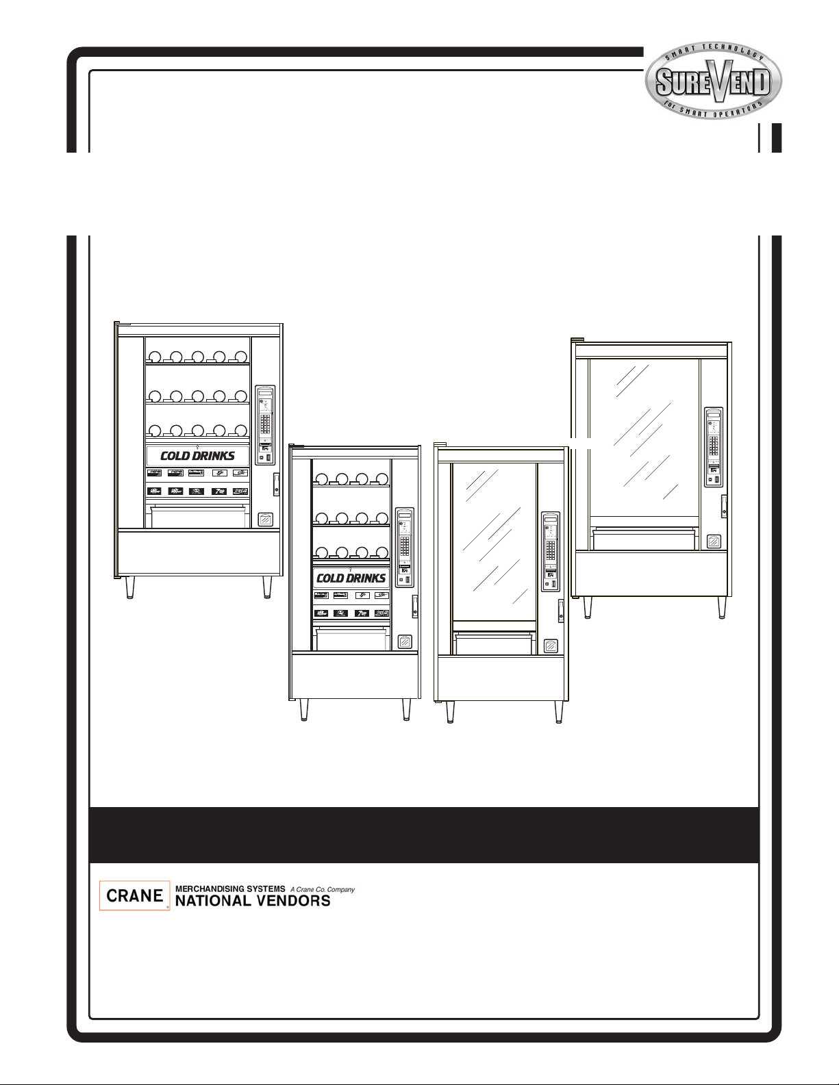
Models 167, 177, 168, 457, 458, 764, 765, 784, 787
Snack/Refreshment Center 2
Snack Center 4
NATIONAL VENDORS
CRANE
ABC
DEF
GHJ
123
456
789
0#
Q
NATIONAL VENDORS
CRANE
ABC
DEF
GHJ
123
456
789
0#
Q
NATIONAL VENDORS
157P0004
CRANE
ABC
DEF
GHJ
123
456
789
0#
Q
NATIONAL VENDORS
CRANE
ABC
DEF
GHJ
123
456
789
0#
Q
797
798
167
177
457
764
784
787
168
458
765
Set-Up & Operators’ Guide
12955 Enterprise Way
Bridgeton, Missouri 63044-1200
(314) 298-3500 / Service: (800) 628-8363
www.CraneMS.com
Copyright© 12-06
1670097
Page 2

How to use this guide
Since your merchandiser came equipped with a can module, the Snack Center Setup and Operator's
Guide has instructed you to get this booklet to continue your setup. Follow the steps for setting up your
can module, then return to the spot in the Setup and Operator's Guide that sent you here. You may
notice some other books in your plastic bag, also. The Programming Guide is a reference for you to use
later, after your machine is up and running. Use the Programming Guide to access the many advanced
features included with your machine.
DO NOT DISPOSE OF THIS BOOKLET! Even though you may have finished with it today, you
might find the need to set your merchandiser up again. We recommend returning it to the plastic bag, and
storing it inside the cabinet. That way, it is readily available at a future time.
This machine has been engineered to our own rigid safety and performance standards. It has been
designed to comply with sanitation and health guidelines recommended by the Automatic Merchandising Health-Industry Council (AMHIC) and it conforms with all other NAMA safety recommendations.
This machine has been manufactured in accordance with the safety standards of both Underwriter’s
Laboratories and the Canadian Standards Association. To maintain this degree of safety and to continue to achieve the level of perf orma nce built into this machine, it is important that installation a nd
maintenance be performed so as to not alter the original construction or wiring, and that replacement parts are as specified in the Parts Manual. Your investment in this equipment will be protected by using this Setup and Operator's Guide and the Par ts Manual in your operation, service
and maintenance work. By following the prescribed procedures, machine performance and safety
will be preserved.
Page 3

Snack / Refreshment Center Setup and Operator's Guide
Table of Contents
Preliminary.......................................................................................................................................... 5
Initial Set-Up.......................................................................................................................... .......... ... 9
1. MOVE THE MERCHANDISER THROUGH A NARROW DOORWAY............ .................... .............. . 9
remove the top panel: 9
remove the bottom panel: 9
take the merchandiser through the opening: 10
reassemble the merchandiser: 10
2. POSITION THE MERCHANDISER......... .............. ............... .................... .............. .............. ........... 10
Snack Se ction Set- U p.................. .................... .............. ..................... .................... ........................... 12
1. PLACE A TRAY IN THE LOADING POSITION...... ............... .............. .............. .................... ......... 12
1. SET UP TRAYS TO VEND PRODUCTS................ ............... .................... .............. .............. ........... 13
2. SET UP A TRAY TO VEND WIDE PRODUCTS.. ........ ..................... .............. .............. ................. 1 3
3. REMOVING A TRAY ...... .............. .............. .............. ..................... .............. .............. .............. ..... 14
4. REMOVING AND INSTALLING COLUMN DIVIDERS ........ .............. .............. .................... ........... 1 6
5. OPERATE A TRAY OUTSIDE THE MACHINE.............. ............... .................... .............. .............. . 16
1. REPLACING A MOTOR WITH A SPIRAL BEARING.... ......... .................... .............. .............. ....... 17
removing a motor: 17
installing a spiral bearing: 17
disconnecting a motor harness: 18
connecting a motor harness: 18
2. CONNECTING AND DISCONNECTING A MOTOR HARNESS .. ........ .............. .................... ........... 1 8
3. REMOVING AND INSTALLING SPIRALS.... ........ ..................... .............. .............. .................... ..... 19
to remove a spiral: 20
to install a spiral: 20
should i use a clockwise or a counterclockwise spiral? 20
1. REMOVING A SPIRAL COUPLER .................... ............... .............. .................... .............. ............. 21
22
1. REMOVING AND INSTALLING A SPIRAL MOTOR ............. .............. .............. .................... ......... 22
removing a spiral motor: 22
installing a spiral motor: 22
when are gears used? 23
where are the gears placed? 23
how is the gear oriented? 23
2. INSTALLING A GEAR..... .................... .............. ............... .................... .............. .............. ............. 23
3. INSTALLING A SPIRAL COUPLER. .................... ............... .............. .................... .............. ........... 2 4
4. MOVING A TRAY UP OR DOWN... .............. ..................... .............. .............. .................... ........... 2 6
5. INSTALLING A TRAY IN THE MERCHANDISER..................... .............. .................... .............. ..... 27
10. INSTALLING AND REMOVING A PRODUCT SPACER..... ........ .............. .................... .............. ... 2 8
loading a tray with products in general: 29
special considerations: 29
1. LOAD TRAYS WITH PRODUCT....................... ............... .............. .................... .............. ............. 29
spiral wall retainer usage: 30
B.. LOAD TRAYS WITH PRODUCT (CONTINUED)................ .............. .................... .............. ......... 31
preparing the merchandiser for vending "lunch bucket": 31
preparing the merchandiser for vending "top shelf": 32
1. RETURN THE TRAYS TO THE VENDING POSITION....... ........ .................... .............. .............. ..... 33
1670097 Page i December 2005
Page 4

Snack / Refreshment Center Setup and Operator's Guide
Table of Contents
installing price labels: 34
2. INSTALL AND SET PRICE LABELS.............. .............. ..................... .............. .............. ................. 3 4
adjusting the price roll: 35
installing selection id numbers: 36
3. INSTALL SELECTION ID LABELS....... .............. .............. ..................... .............. .............. ........... 36
which id label goes with which selection? 37
Set Up The Gum and Min t Unit .................. .............. ..................... .................... .............. .............. . 38
1. INSTALL PRICE LABELS ............... .............. .................... ............... .............. .................... ........... 38
2. PUT THE GUM AND MINT DISPENSER IN THE LOADING POSITION........ .................... ............. 38
3. LOAD THE GUM AND MINT DISPENSER WITH PRODUCT........................................................ 39
5. REMOVING AND INSTALLING COLUMN REDUCERS........ ............... .............. .............. ............... 40
to remove a column reducer: 40
to install a column reducer: 40
4. RETURN THE GUM AND MINT DISPENSER TO THE VENDING POSITION...... ........ .............. ..... 40
Final In stall a ti o n........ .................. ............ .................. ............ ................. .................. ........................ 41
1. LEVEL THE MERCHANDISER.......... .............. .................... ............... .............. .................... ......... 41
method 1: 42
method 2: 42
1. INSTALL THE BASE PLATE......................... .............. ............... .................... .............. .............. ... 44
3. INSTALL THE OPTIONAL CASH BOX LOCK .......... ............... .................... .............. .............. ..... 45
2. INSTALL THE LOCK CYLINDER ..................... .............. ............... .................... .............. ............. 45
1. SET UP THE COIN MECHANISM................. .............. ............... .................... .............. .............. ... 4 6
1. LOAD THE COIN MECHANISM..... .............. .................... ............... .............. .................... ........... 4 7
Programming .................................................................................................................................... 48
the service keypad 48
1. SET PRICES ................................................................................................................................. 48
2. VIEW THE CHILLER OR CAN UNIT TEMPERATURE..... ......... .............. .................... .............. ... 4 8
Final Checkout....................................................................................................................... ........ ... 4 9
1. TEST VEND SELECTIONS................ .............. .................... ............... .............. .................... ......... 49
2. OPERATIONAL READINESS CHECK ..... .............. .............. ............... .................... .............. ......... 49
4. SPIRAL INDEXING PROCEDURE
(TWO SPIRALS, ONE OR TWO MOTORS)... ........ .............. ............... .................... .............. .............. . 50
3. SPIRAL INDEXING PROCEDURE (ONE SPIRAL, ONE MOTOR)................................................. 50
5. TESTING THE BILL VALIDATOR ................ .............. ............... .................... .............. .............. ... 5 1
December 2005 Page ii 1670097
Page 5
Snack / Refreshment Center Setup and Operator's Guide
NATIONAL VENDORS
CRANE
ABC
DEF
GHJ
123
456
789
0#
Q
NATIONAL VENDORS
CRANE
ABC
DEF
GHJ
123
456
789
0#
Q
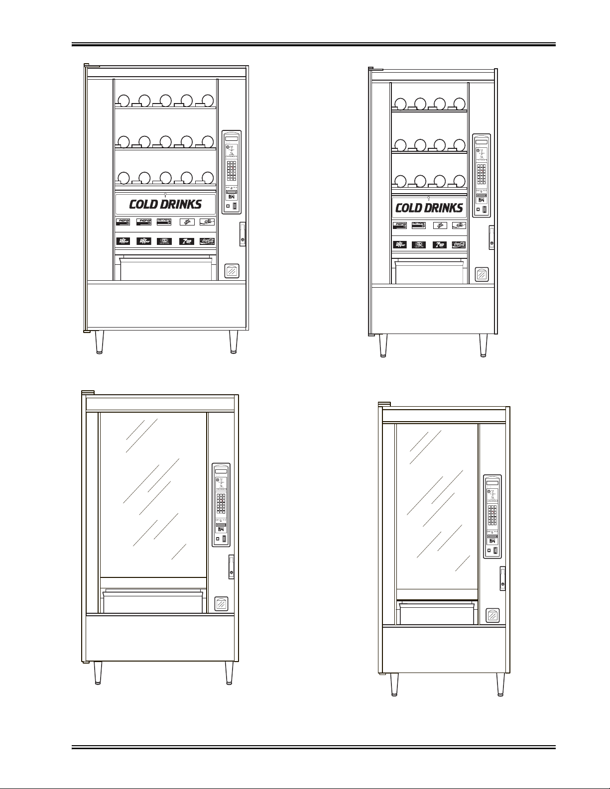
797, 798
784, 787
NATIONAL VENDORS
CRANE
NATIONAL VENDORS
ABC
DEF
GHJ
123
456
789
Q
0#
CRANE
ABC
DEF
GHJ
123
456
789
0#
Q
167, 177
457, 764
168, 458
765
157p0296
1670097 Page 1 December 2005
Page 6
Snack / Refreshment Center Setup and Operator's Guide
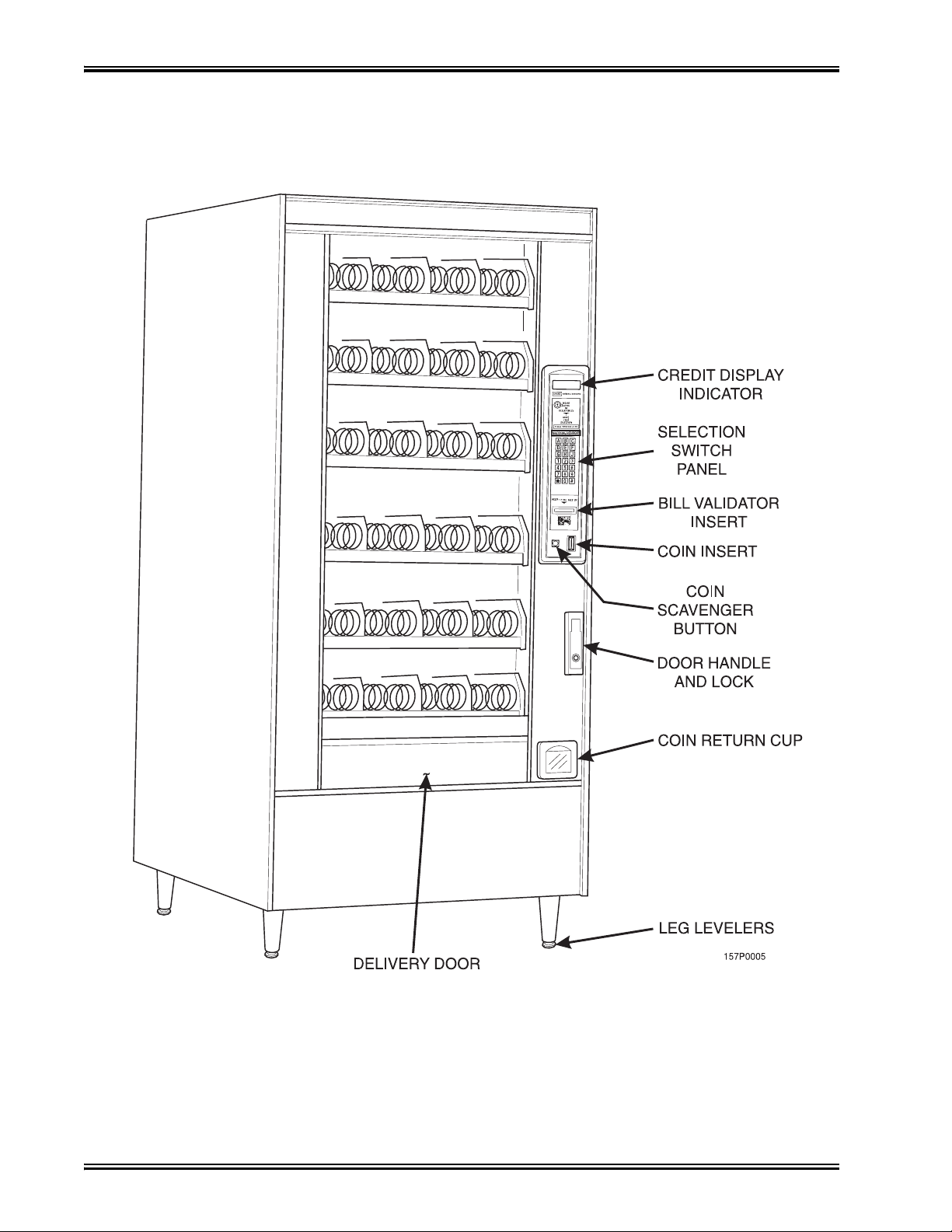
Model 168 - Exterior View
(Models 167, 457, 458, 764, 765 have similar appearance)
December 2005 Page 2 1670097
Page 7
Snack / Refreshment Center Setup and Operator's Guide
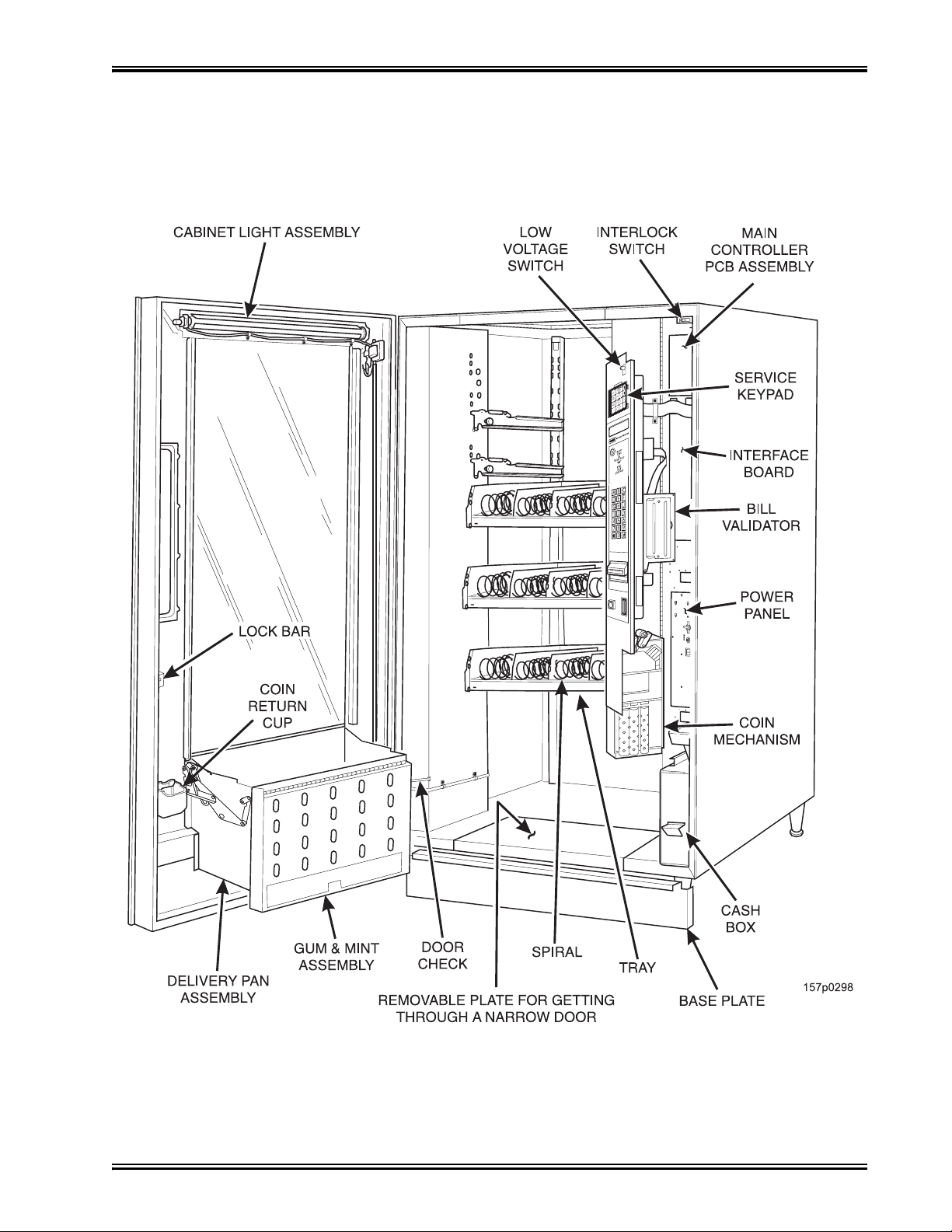
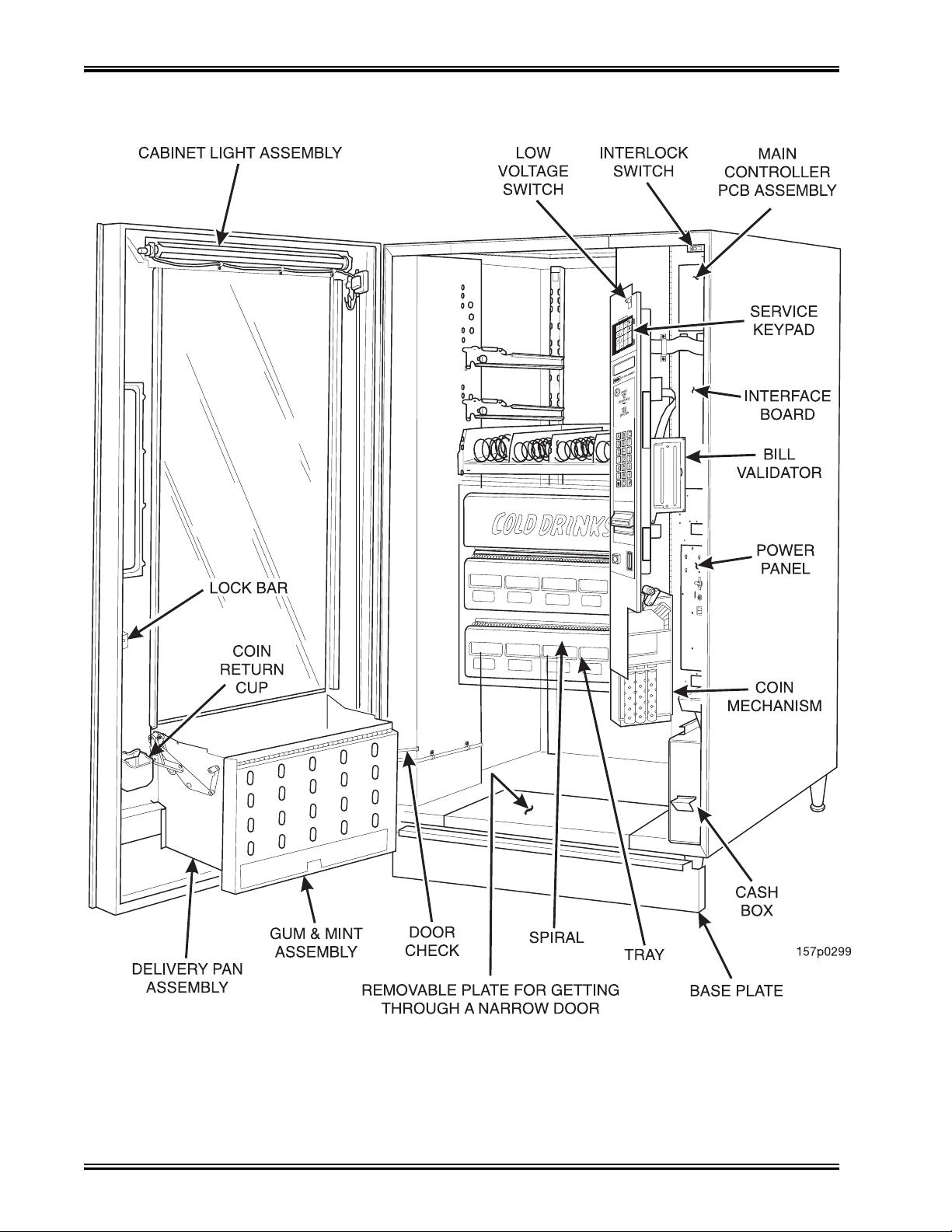
Model 168 - Interior View
(Model 167 has similar appearance)
1670097 Page 3 December 2005
Page 8
Snack / Refreshment Center Setup and Operator's Guide
Model 797 - Interior View
December 2005 Page 4 1670097
Page 9

Snack / Refreshment Center Setup and Operator's Guide
Preliminary
Power Requirements
The merchandiser is supplied with a service cord for the country of use and is terminated in a grounding type plug. The wall receptacle used for this merchandiser must be properly polarized, grounded,
and of the correct voltage. Operating the merchandiser from a source of low voltage will VOID
YOUR WARRANTY. Each merchandiser should have its own electrical circuit and that circuit
should be protected with a circuit breaker or fuse conforming to local regulations.
1. Voltage Check - Place the leads of a voltmeter across the LINE (LIVE) and NEUTRAL termi-
nals of the wall receptacle. The voltmeter should indicate 110-130 volts ac for 120 volt, 60 Hz
locations, or 220- 240 volts ac for 230 volt, 50 Hz locations.
2. Polarity Check - Place the leads of a voltmeter across the LINE (LIVE) and GROUND termi-
nals of the wall receptacle. The voltmeter should indicate 110-130 volts ac for 120 volt, 60 Hz
locations, or 220- 240 volts ac for 230 volt, 50 Hz locations.
3. Noise Potential Check - Place the test leads of a voltmeter across the NEUTRAL and
GROUND terminals of the wall receptacle. The meter should indicate 0 volts ac. A measurement greater than 1.5 - 2.0 volts ac could result in problems for the merchandiser's electronic
circuitry caused by electrical noise.
Any deviation from these requirements could result in unreliable performance from your merchandiser.
Unpack the Machine
Remove all packing materials from the interior of the machine. Keep all documents; warr ant y cards,
etc. Set aside the base plate kit (if present).
1670097 Page 5 December 2005
Page 10
Snack / Refreshment Center Setup and Operator's Guide
INTERLOCK SWITCH. When the cabinet door is open, this switch turns off the glass heater,
o
L
s.
M
t
e
d
c
,
a
F
p
S
m
C
r-
c
B
t
S
v
e
m
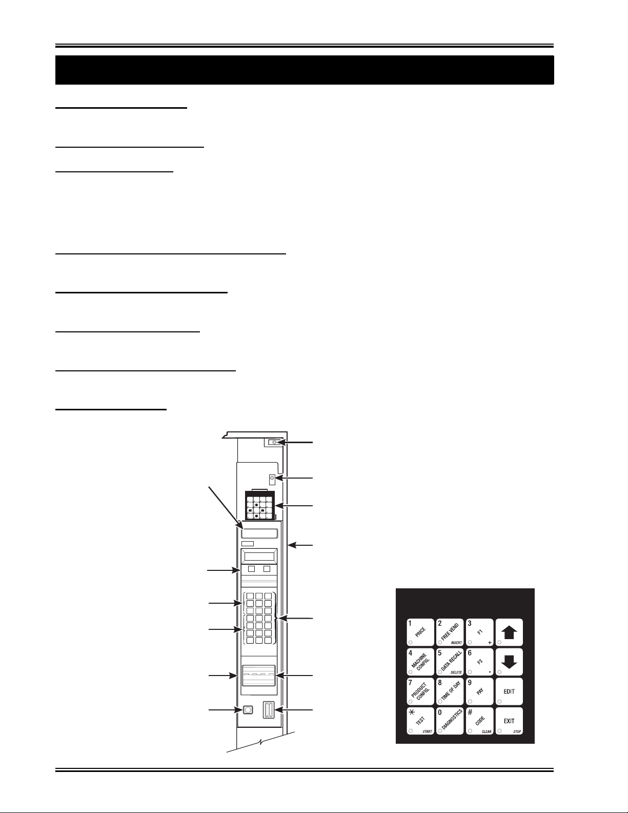
Controls and Indicators
ptional fan (if so equipped) and turns on the service light (not present on all models).
OW VOLTAGE SWITCH. Informs the controller software of the main door open or closed statu
ESSAGE DISPLAY. This is how the merchandiser communicates with the outside world. Cus-
omers can see messages about how much money they have put into the merchandiser. The messag
isplay also tells customers when a sel ecti on is sold out and when vending is free, inhibited, or disounted. The message display shows you what you are doing when you program the merchandiser
nd can show you what is wrong if there is a failure.
REE VEND KEYSWITCH (OPTIONAL). This allows someone (other than maintenance
ersonnel) to set the merchandiser to free vend without opening the door.
ELECTION SWITCH PANEL. The customer uses these switches to make selections. Also,
aintenance people may use this switch panel during programming and other support modes.
OIN RETURN BUTTON. Pressing this button returns any coins that have been paid into the me
handiser prior to a vend.
ILL ACCEPTOR (OPTIONAL). Accepts bills in various denominations, depending upon the
ype of bill validator, and how the machine is configured.
ERVICE KEYPAD. The service keypad is located at the top of the monetary panel. It gives ser-
ice personnel the means to program, retrieve data from, and view diagnostic information about, th
erchandiser.
MESSAGE
DISPLAY
FREE
FREE
TEST
DATAPRICE
VEND
VEND
DRY
PAYOUT
CONF.
PROD.
LIQUID
HOME
PROD.
TIME
ENTER/
SERVICE
OF
ACTION
DAY
INTERLOCK
SWITCH
LOW VOLTAGE
SWITCH
SERVICE
KEYPAD
NATIONALVENDORS
ACT
CREDIT
CARD READER
LETTERS
A-H,J
NUMERALS
1-9, *,0, #
MONETARY
PANEL
COIN
RETURN
BUTTON
CRANE
INSERT
COINS
OR
DOLLARBILLS
MAKE
YOUR
SELECTION
CHANGERETURNED BELOW
AB
DEF
G
H
12
56
4
789
0#
Q
C
J
3
157P0086
CABINET
SELECTION
SWITCH
BILL
ACCEPTOR
COIN
INSERT
December 2005 Page 6 1670097
Page 11
Snack / Refreshment Center Setup and Operator's Guide
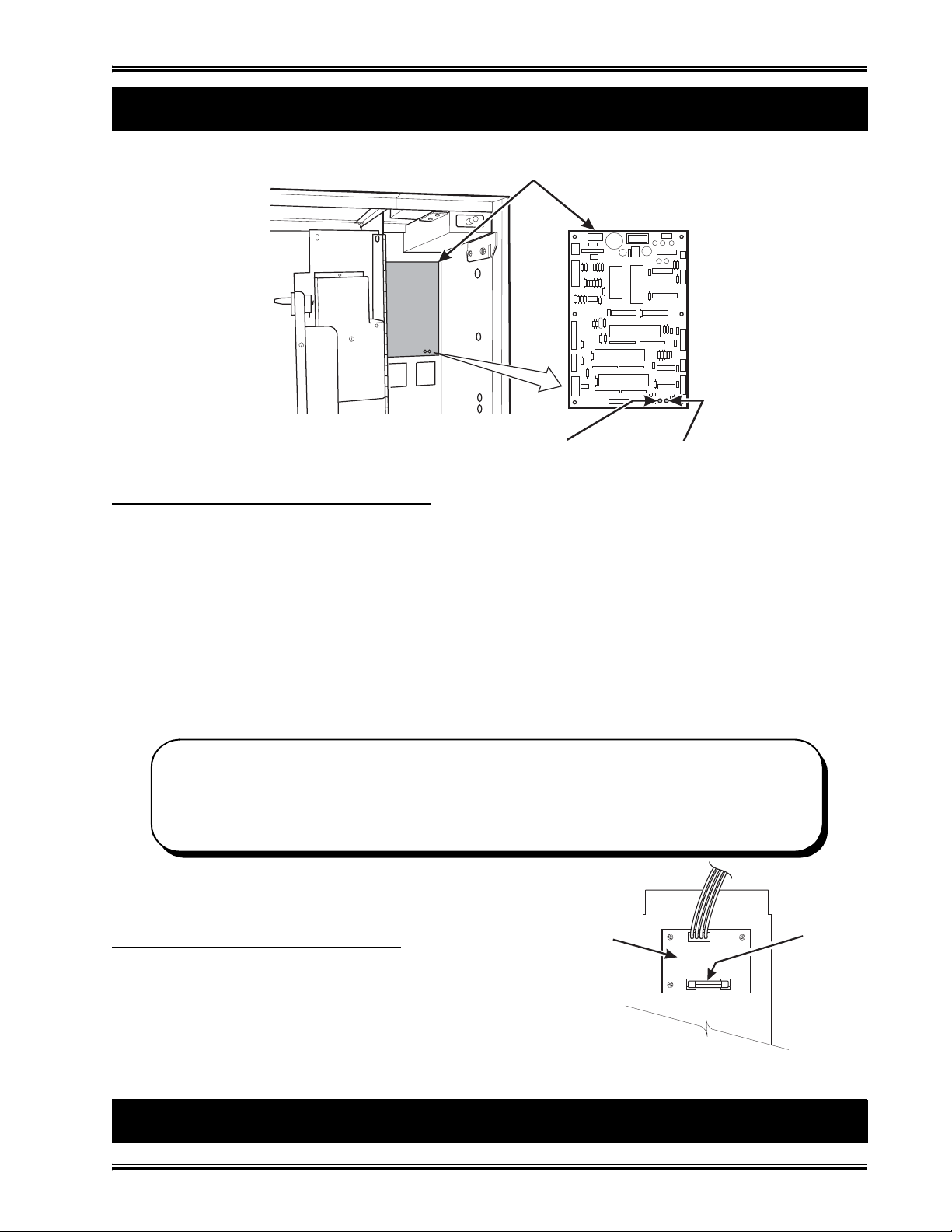
MAIN CONTROLLER
T
1
E
P
U.S. / CANADA POWER CONTROL PANEL
B
b
p
t
s
c
a
t
Controls and Indicators (continued)
PCB ASSEMBLY
LED1LED2
POWER ON
(LED 1)
FLASHING
HEARTBEA
(LED 2)
MAIN CONTROLLER PCB DISPLAY. This display consists of two light emitting diodes (LED)
mounted on the controller PCB.
POWER ON
(L.E.D. 1)
HEARTBEAT
(L.E.D. 2)
"CAUTION - Risk of explosion if battery is replaced with an incorrect type. Dispose of used batteries according to the manufacturer's instructions."
When lit, this red LED indicates electrical power is applied to
the controller PCB.
When flashing, this red LED indicates that the controller PCB
is active, and the software is operating.
NORMAL CONDITIONS:
When the merchandiser is operating normally, you should see a steady red POWER
ON indicator and a flashing red HEARTBEAT indicator. Contact a service represen-
tative if any other condition exists.
TOP
DC POWER
ack Side of U.S./Canada Power Panel. The circuit
oard mounted on the rear of the power panel is a dc
ower supply for the coin mechanism. A fuse protects
he board circuitry in the event of a coin mechanism
olenoid failure. If the coin mechanism is not working,
heck this fuse. If the fuse is blown, a bad coin mechnism solenoid could be at fault. (Board may not be
here if machine is setup for MDB.)
How to Turn the Merchandi ser ON and OFF
1670097 Page 7 December 2005
SUPPLY PCB
FOR 110V COIN MECH
˜
BACK SIDE
OF
AGC
FUS
1 AM
Page 12
Snack / Refreshment Center Setup and Operator's Guide
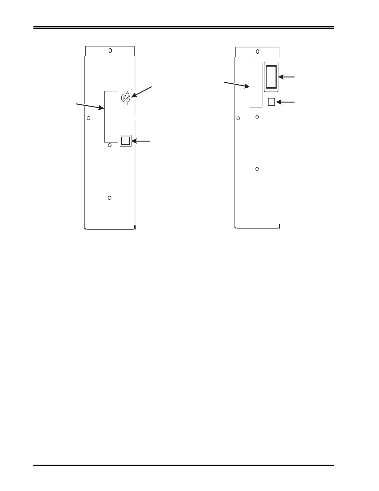
I
LABEL
MAIN
ON
OFF
POWER
SWITCH
LABEL
O
LOW VOLTAGE
CIRCUIT BREAKER
626P0039
U.S./CANADA POWER PANEL INTERNA TI ONAL POWER P ANEL
MAIN
POWER
SWITCH
ELECTRONICS
BREAKER
626P0005
• Power to the merchandiser is controlled by the main power switch, located on the power panel.
• The power panel is on the right side of the merchandiser, behind the monetary door.
WARNING
Lethal voltages are present. Unplug the merchandiser whenever
you do one of the following tasks:
• Change a fuse
• Change the fluorescent lam p
• Change the lamp st a r ter
• Connect or dis connect a harness (except a motor harn ess when
the tray has been removed)
Failure to do so may result in personal injury .
December 2005 Page 8 1670097
Page 13
1. Move the Merchandiser Th rough a Narrow Doorway
H
VIEW LOOKING INTO THE BOTTOM OF THE CABINET
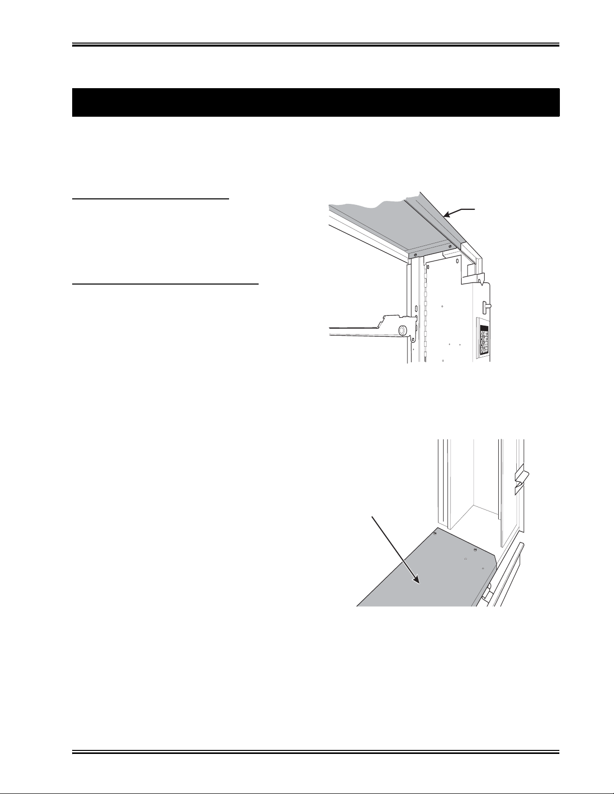
REMOVE THE TOP PANEL:
1
2
R
1
2
NOTE: If necessary, this merchandiser can be moved through an opening as narrow as 30
inches by removing panels at the top and bottom of the cabinet.
only 28” deep, and do not require panels to be removed.
. Remove the two screws that secure each end of
the panel to the cabinet.
. Pull the panel forward to remove it from the
merchandiser.
EMOV E THE BO TTOM PANEL:
. Remove the screws that secure the panel to the
cabinet.
. Pull the panel forward to remove it from the
cabinet.
Snack / Refreshment Center Setup and Operator's Guide
Initial Set-Up
Merchandisers 457 and 458 are
REMOVABLE PANEL
FOR GETTING THROUG
A NARROW DOORWAY
VIEW LOOKING INTO THE TOP OF THE CABINET
REMOVABLE PANEL
FOR GETTING THROUGH
A NARROW DOORWAY
˜
1670097 Page 9 December 2005
Page 14
Snack / Refreshment Center Setup and Operator's Guide
T
T
1
2
R
C
1
1. Move the Merchandiser Th rough a Narrow Doorway
(continued)
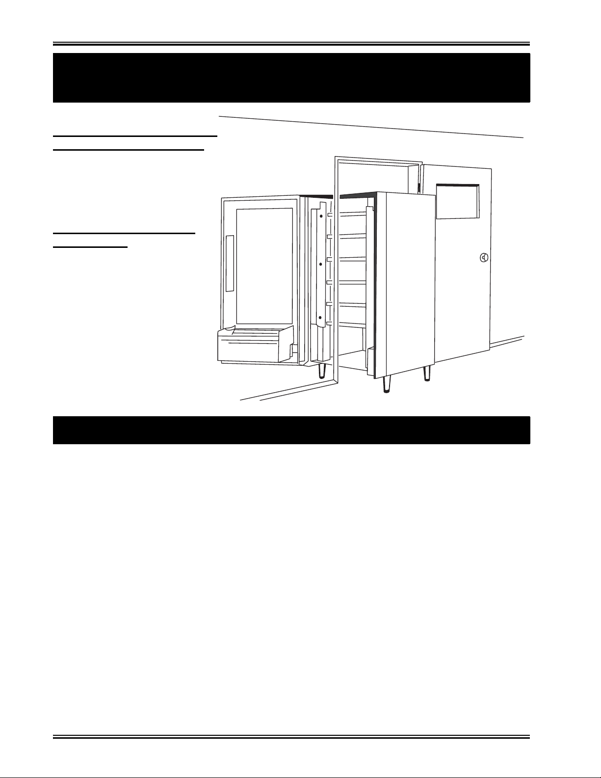
AKE THE MERCHANDISER
HROUGH THE OPENING:
. Open the cabinet door and place it square with the
left side of the cabinet.
. Carefully walk the merchan-
diser through the opening.
EASSEMBLE THE MERHANDISER:
. Replace the upper and lower
panels.
2. Position the Merchandiser
Move the merchandiser to its approximate position. (There are some procedures you need to do
before it is in its permanent location.) Plug in your merchandiser and turn the power switch to ON.
• You can position this merchandiser anywhere in a bank of machines. It can even be placed on an
end flush against a side wall.
• The 167 and 168 merchandisers should be located at least one inch away from the back wall.
• The 764, 765, 784, 787, 797, and 798 merchandisers should be placed at least six inches away
from the back wall. This will provide adequate air circulation for the refrigeration unit.
• The 764, 765, 787, 797, and 798 merchandisers will operate more efficiently when placed in a
shaded location.
• There should be enough room in front of the merchandiser for the door to move freely.
WARNING
This machine is only rated for installation in an indoor location.
December 2005 Page 10 1670097
Page 15
Snack / Refreshment Center Setup and Operator's Guide
Time Out!
Now that you have placed your machine near its permanent location, you need to set up some of the
special options you may have.
NOW, IF YOUR MACHINE IS EQUIPPED WITH A CAN-
MODULE . . .
Grab the booklet entitled "CAN MODULE SETUP AND OPERATOR'S GUIDE" and follow the
setup procedures contained in it. After you have done that, come right back here and proceed with the
next step.
N
E
X
T
Go on to the next page and continue with the snack set up.
1670097 Page 11 December 2005
Page 16
Snack / Refreshment Center Setup and Operator's Guide
Snack Section Set-Up
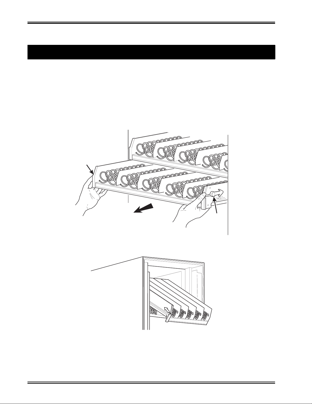
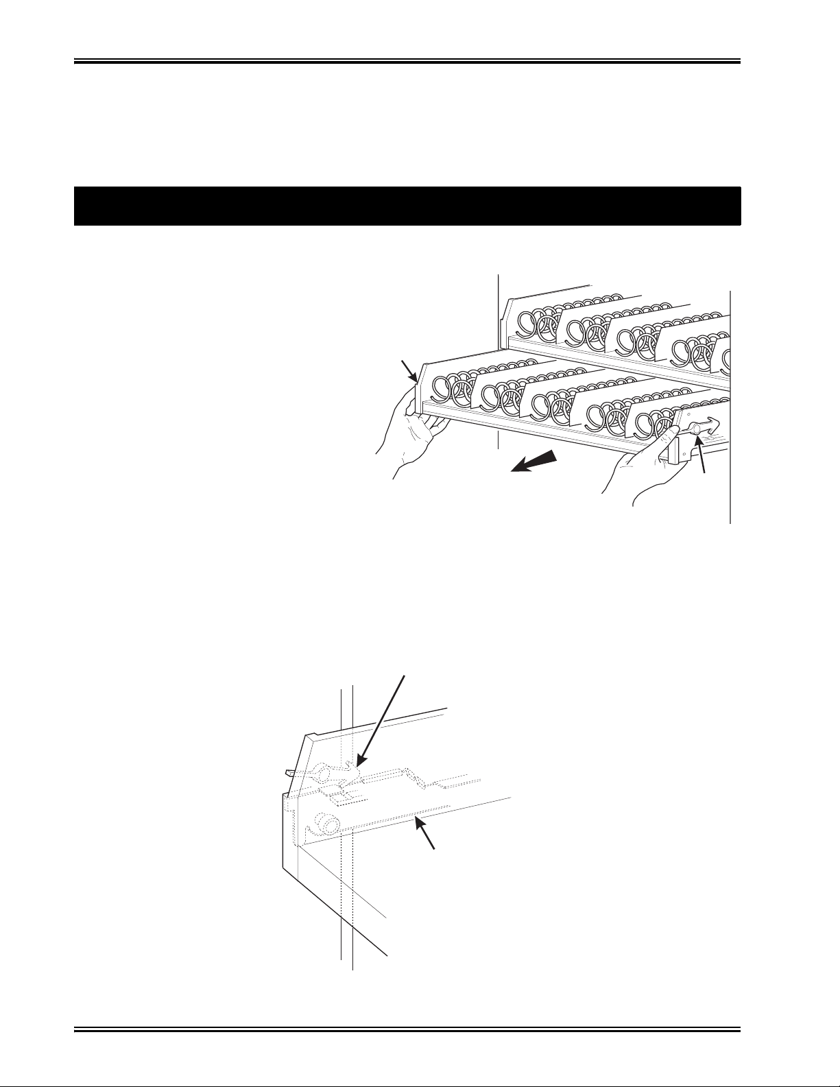
1. Place a Tray in the Loading Position
2. Place both hands on the tray as shown.
3. If your machine has tray latches, lightly push back on the tray with your palms. This will
release the tray latches on the sides of the tray. Otherwise, skip to step 5.
4. Push down on the tray latches with your thumbs.
5. Pull the tray toward you until you hear and feel the rear tray rollers drop into a cut-out in the top
of the guide rail. Skip to step 6
6. Lightly lift the front of the tray and pull the tray toward you until you hear and feel the tray roll-
ers drop into the cut-out in the top of the guide rail.
.
TRAY
LATCH
PULL
TRAY
LATCH
157P0011
7. Continue pulling the tray forward for another inch. You will then be able to tilt the tray down-
ward into the loading position as shown.
NOTE
When the cabinet door is not fully open, the bottom tray will rest
on the delivery pan assembly. Handle the tray with care to avoid
scratching the delivery pan assembly.
December 2005 Page 12 1670097
Page 17

Snack / Refreshment Center Setup and Operator's Guide
1. Set up Trays to Vend Products
These instructions will guide you through setting up your trays for vending. You will be asked to
determine if your tray can physically hold the products you intend to vend. If not, you will be
directed to other procedures which will help you get them set up. Follow these nine steps for each
tray in your machine:
1. Make sure the tray is in the loading position.
2. Is the column wide enough for the intended product? If so, proceed to the next step. Otherwise,
set up your tray to vend wider products ( see below, this page). When you're done, return to step
3 in this procedure.
3. Will the products fit between the spiral turns? If so, proceed to the next step. Otherwise,
change the spiral.
4. Will the product pass under the tray immediately above? If so, proceed to the next step. Other-
wise, reposition the tray and guides.
5. Will the product touch products on either side? I f not, proceed to the next step. Otherwise,
install a product spacer.
6. Load products in the tray.
7. Return the tray to the vending position.
8. Install the price rolls.
9. Install the selection ID numbers.
2. Set Up A Tray To Vend Wide Products
The following steps will help you configure your tray to vend wide products. When you have completed the procedures called out in each step, return to the next step in the procedure. When you are
done with the entire wide product steps, return to the set-up procedures above.
1. Remove the tray from the merchandiser and place on a flat surface.
2. Based on the size of the product you want to vend, decide how many spiral positions it will
occupy . Please remember that the leftmost spiral in the group must have an even ID number (0,
2, 4, etc.) For example, if a product is three spirals wide, the left spiral will be ID number 0, and
the right spiral will be ID number 2. Be careful how wide you set up for, because really wide
products could get hung up in the delivery door.
3. Remove the column dividers inside the group. In the example of three spiral positions, you
would be removing the dividers between spiral ID numbers 0 and 1, and 1 and 2.
4. If your group only consists of 2 spirals, replace the rightmost motor with a spiral bearing and
gear, and install a gear on the leftmost motor. Skip to step 8.
5. Remove all spirals in the group except the leftmost spiral.
6. Do one of the following:
a. If your group has an ODD number of spirals (3, 5, etc.) remove the harnesses from all
motors in the group except the leftmost one. To the rightmost motor, connect the harness
from the motor immediately to its left.
b. If your group has an EVEN number of spirals (4, 6, etc.) remove the harnesses from all
motors inside the group (leave the harnesses connected to the leftmost and rightmost
motors).
1670097 Page 13 December 2005
Page 18
Snack / Refreshment Center Setup and Operator's Guide
Study this procedure before you install a
t
t
P
1
2
3
4
y
TRAY
7. Install a spiral at the rightmost position in your group. Make sure it has the same product capac-
ity and is opposite to the one in the leftmost position.
8. Return the tray to the merchandiser.
9. Electronically couple the motors as needed (see your Programming Guide for information).
10. Return to step 3 in the Set Up Trays to Vend Products procedure, above.
ray for the first time; while you are holding
he tray you will not be able to see this area.
roceed as follows:
. If your machine has tray latches, push
with your palms. This releases the
tray latches. Otherwise, skip to step 4.
. Push down on the tray latches with
your thumbs.
. Pull the tray forward until you hear
and feel the rear tray rollers drop into
a cut-out in the top of the guide rail.
3. Removing a Tray
TRAY
LATCH
PULL
TRAY
LATCH
157P0011
. Lightly lift the front of the tray and pull the tray toward you until you hear and feel the rear tra
rollers drop into a cut-out in the top of the guide rail.
LATCH
TRAY
GUIDE
RAIL
157P0027
December 2005 Page 14 1670097
Page 19

Snack / Refreshment Center Setup and Operator's Guide
CUT-OUT
REAR OF
E
RAIL
5. Unplug the tray wiring harness from
6
3. Removing a Tr ay (conti nued)
the PC board mounted on the tray
guide rail JUST ABOVE the tray you
are removing.
PC BOARD
ATTACHED TO
TRAY GUIDE
TRAY GUIDE RAIL
. Lift up on the tray and slide it toward the back.
No more than an inch should be needed
TRAY
7. The tab near the back of the tray should align with the cutout in the top of the guide rail as shown.
8. Lift the tray clear of the guide rail and out of the merchandiser.
TAB
(ON TRAY)
TRAY GUID
CAUTION
When the cabinet door is not fully open, use extra care in removing
the bottom tray. Failure to do so may result in damage to the tray
or to the delivery pan assembly.
TRAY
ROLLER
REAR OF TRAY
TRAY
GUIDE
RAIL
157P0026
1670097 Page 15 December 2005
Page 20

Snack / Refreshment Center Setup and Operator's Guide
DIVIDER
1. Push the column divider toward the back of
2
3
4. Removing and Ins talling Column Dividers
the tray - .
. Lift the column divider clear of the tray -
.
2
. Install the column divider in the reverse
order of removal.
1
1
2
COLUMN
5. Operate a Tray Outside the Mach i ne
Tray harness extension (P/N 1709017) is available from your National Vendors Parts department.
The extension will enable you to remove the tray from the machine and still operate the motors and
spirals. Connect it as shown:
December 2005 Page 16 1670097
Page 21

Snack / Refreshment Center Setup and Operator's Guide
SPIRAL
R
1. Replacing a Motor With a Spiral B e aring
REMOVING A MOTOR:
1. Disconnect the harness from the motor.
(See CONNECTING AND DISCONNECTING A MOTOR HARNESS), below.
2. Remove the spiral. (See REMOVING AND INSTALLING SPIRALS).
3. Remove the spiral coupler. (See REMOVING A SPIRAL COUPL ER) .
4. Remove the motor. (See REMOVING AND INSTALLING A SPIRAL MOTOR).
INSTALLING A SPIRAL BEARING:
1. Put the gear into position if required in this set-up as shown. (See INSTALLING A GEAR).
2. Install the spiral coupler. (See INSTALLING A SPIRAL COUPLER).
BEARING
BACKWALL
OF TRAY
GEAR
˜
SPIRAL
COUPLE
1670097 Page 17 December 2005
Page 22

Snack / Refreshment Center Setup and Operator's Guide
CAUTION
D
1
2
C
1
2
2. Connecting and Disconnecting a Motor Harness
To avoid breaking the motor circuit board, hold the header on the
circuit board whenever connec ting or disconnecting a motor harness.
ISCONNECTING A MOTOR HARNESS:
. Pull the harness connector away from the circuit board as shown.
. Tuck the unused part of the harness out of the way in the trough at the back of the tray.
ONNECTING A MOTOR HARNESS:
. Locate the harness connector for the appropriate tray position.
. Push the harness connector over the header pins on the motor circuit board as shown.
December 2005 Page 18 1670097
Page 23

Snack / Refreshment Center Setup and Operator's Guide
• All spirals are the same diameter:
•
3. Removing and Installing Spirals
There are two types of spirals:
COUNTER-CLOCKWISE (left hand) CLOCKWISE (right hand)
• Spirals are available in eight dif ferent capacities. Four of the s e are standa rd, and f our a re options .
ITEM CAPACITY
OF SPIRAL
6 (Optional) 1477104 1477102 Purple
11 (Standard) 1477027 1477024 Blue
13 (Standard) 1477033 1477030 Yellow
15 (Standard) 1477039 1477036 Red
20 (Standard) 1477045 1477042 White
25 (Optional) 1477051 1477048 Green
30 (Optional) 1477057 1477054 Black
38 (Optional) 1477063 1477060 Orange
PART NUMBER
CLOCKWISE
(RH)
COUNTER
CLOCKWISE (LH)
CLIP
COLOR
1670097 Page 19 December 2005
Page 24

Snack / Refreshment Center Setup and Operator's Guide
LIFT
3. Removi ng and Installing Spirals (cont inued)
SPIRALS FOR MODELS 172, 173, 452, AND 453
PART NUMBER
ITEM CAPACITY
OF SPIRAL
CLOCKWISE
(RH)
COUNTER
CLOCKWISE (LH)
8 1707017 1707019 Grey
10 1707005 1707007 Blue
12 1707009 1707011 Yellow
14 1707013 1707015 Red
18 1707021 1707023 White
TO REMOVE A SPIRAL:
1. Pull forward on the retaining clip and remove the end of the spiral from the spiral coupler as
shown.
2. Remove the spiral from the tray.
PULL
SPIRAL
COUPLER
CLIP
COLOR
SPIRAL
RETAINING
TO INSTALL A SPIRAL:
CLIP
1. Pull the bottom of the retaining clip toward the front of the spiral.
2. Lower the spiral into the tray column and insert the end of the spiral into the spiral coupler as
shown.
3. Release the retaining clip.
SHOULD I USE A CLOCKWISE OR A COUNTERCLOCKWISE SPIRAL?
1. The type of spiral used is determined by the column position it will occupy in the tray.
2. Refer to the figure below to find the correct spiral type.
A1 A2
December 2005 Page 20 1670097
A3
A4
A5 A6
A7
A8 A9A0
Page 25

Snack / Refreshment Center Setup and Operator's Guide
1. Removing a Spiral Coupler
1. Pinch together the prongs on the end of the spiral coupler as shown.
2. Pull the coupler forward (in the direction of the arrow as shown)
SPIRAL
COUPLER
PRONGS
PULL
1670097 Page 21 December 2005
Page 26

Snack / Refreshment Center Setup and Operator's Guide
R
SPIRAL
1
2
3
4
5
6
I
1
2
3
4
.
5
6
1. Removing and Installing a Spiral Motor
REMOVING A SPIRAL MOTOR:
NOTE:
Some steps may already be complete d.
. Remove the tray. (See REMOVING A TRAY).
. Disconnect the motor harness.
(See CONNECTING AND DISCONNECTING A
MOTOR HARNESS).
. Remove the spiral.
(See REMOVING AND INSTALLING SPIRALS).
. Remove the spiral coupler.
( See REMOVING A SPIR AL COUPLER).
. Lift the motor clear of the tray.
. Return the tray to the merchandiser.
(See IN STALLING A TRAY IN THE MERCHANDISER).
NSTALLING A SPIRAL MOTOR:
MOTOR
BACKWALL
OF TRAY
GEAR
˜
SPIRAL
COUPLE
. Remove the tray. (See REMOVING A TRAY).
. Place the motor in the correct position at the rear of the tray as
shown.
. Place a gear in position if required by this set-up.
(See INSTALLING A GEAR).
. Install a spiral coupler in the proper orientation. (See INSTALLING A SPIRAL COUPLER)
. Connect the motor harness.
(See CONNECTING AND DISCONNECTING A MOTOR HARNESS).
. Return the tray to the merchandiser.
( See INSTALLING A TRAY IN THE MERCHANDISER).
December 2005 Page 22 1670097
Page 27

Snack / Refreshment Center Setup and Operator's Guide
BACK WALL
ORIENTATION 1 ORIENTATION 2
2. Installing a Gear
WHEN ARE GEARS USED?
• Gears are used to mechanically couple the spirals together.
• This happens whenever you have two spirals and only one motor for vending a selection.
WHERE ARE THE GEARS PLAC ED?
• The gear is placed between the back of the tray and the spiral coupler.
HOW IS THE GEAR ORIENTED?
• There are two possible orientations for the gear:
OF TRAY
GEAR
• There are two rules to follow when orienting gears:
RULE 1-The gears for selections next to each other cannot use the same orientation .
RULE 2-All gears for a single selection mu st use the same orient atio n.
1670097 Page 23 December 2005
Page 28

Snack / Refreshment Center Setup and Operator's Guide
SPIRAL
AS VIEWED FROM FRONT OF TRAY
ONE POSITION
C
ONE POSITION
L
3. Installing a Spiral Coupler
1. Place the gear in position if one is required for this set-up. (See INSTALLING A GEAR).
WHEN USED WITH A MOTOR:
2. Hold the motor in place and push the spiral coupler through the motor gear box until it clicks
into position. Be sure the spiral couplers are oriented as shown below.
NOTE
The motor output shaft opening contains eight
facets to allow the spiral coupler to be installed in any one of
eight p osition s.
COUPLER
FRONT VIEW OF
MOTOR OUTPUT SHAFT
SPIRAL COUPLER ORIENTATION
OUNTERCLOCKWISE
FROM VERTICAL
LEFT SPIRAL
COUPLER
MOTOR
CLOCKWISE
FROM VERTICA
RIGHT SPIRAL
COUPLER
December 2005 Page 24 1670097
Page 29

Snack / Refreshment Center Setup and Operator's Guide
SPIRAL
3. Installing a Spiral Coupler (continued)
WHEN USED WITH A COUPLER BEARING:
3. Hold the coupler bearing in place and push the spiral coupler through the bearing until the coupler clicks into position. Be sure the coupler is in the proper orientation as shown.
COUPLER
SPIRAL
BEARING
1670097 Page 25 December 2005
Page 30

Snack / Refreshment Center Setup and Operator's Guide
Proceed as follows:
1
2
3
4
5
6
7
8
9
1
1
4. Moving a Tray Up or Down
This merchandiser can be adjusted to vend taller products. Some guidelines must be followed:
• Keep in mind that when you increase the product height available to a tray by l owering it, you will
be decreasing the product height available to the tray below.
• If a tray is in the lowest position, the tray below it should not be in the highest position.
• If a tray is in the highest position, the tray above it should not be in the lowest position.
• You will need to experiment with various tray positions to get the best results for your products.
CAUTION:
The trays in a model 764 and 765 merchandiser should not be posi-
tioned over an open air discharge vent.
NOTE:
Tray movement is limited bec ause the tr ay harness will limit the
amount of travel available to the tray guide rails.
. Remove the tray from the merchan-
diser. (See REMOVING A
TRAY).
. Remove the screw that secures
the right tray guide rail to the
front guide mounting channel as
shown.
. Tap up on the guide rail and unseat
the guide rail tabs from the channel slots.
. Pull the guide rail away from the front and rear guide
mounting channels.
. Move the guide rail to the desired position.
. Insert the guide rail tabs into the mounting CVchannel
slots as shown.
. Tap down on the guide rail to seat the tabs in the channel slots.
. Replace the screw that secures the guide rail to the front guide
mounting channel.
. Repeat steps 2 through 8 for the left guide rail.
0. Return the tray to the merchandiser.
( See INSTALLING A TRAY IN THE MERCHANDISER).
1. Load products into the trays, and perform test vends. Make sure the trays don't interfere with
the products you are vending, and that all products vend properly.
REAR GUIDE
MOUNTING CHANNEL
PC BOARD
TRAY
GUIDE
RAIL
SCREW
FRONT GUIDE
MOUNTING CHANNEL
CHANNEL
SLOT
December 2005 Page 26 1670097
Page 31

Snack / Refreshment Center Setup and Operator's Guide
1
2
3
4
5. Installing a Tray in the Merchandiser
• Study this procedure before you install a tray for the first time; while you are holding the tray you
will not be able to see this area. Proceed as follows:
. Insert the tray so that the tray rollers pass
over the tray guide rollers.
5. Hold the tray up while pushing it toward
the rear. Stop when the tab on the tray
aligns with the opening in the tray guide.
REAR OF
TRAY
TRAY
GUIDE
TRAY
ROLLER
157P0024
FRONT OF
RAIL
CUT-OUT
157P0012
TAB
. Bring the tray roller to rest on the tray
guide.
6. Lower the tray until it rests on the tray
guide roller. Push the tray in all the way.
7. The tray latch will fall into the locking
position.
REAR OF TRAY
CUT-OUT
TRAY
ROLLER
TRAY
GUIDE
RAIL
157P0026
REAR OF
TRAY
. Tilt the tray upward.
. Connect the tray wiring harness to the PC
board mounted to the guide rail JUST
ABOVE the tray you are installing.
TAB
(ON TRAY)
157P0025
TRAY GUIDE
RAIL
1670097 Page 27 December 2005
Page 32

Snack / Refreshment Center Setup and Operator's Guide
PRODUCT
DIVIDER
M
G
10. Installing and Removing a Product Spacer
INST ALLING A PRODUCT
SPAC ER:
The product spacer will keep a
tall, narrow product upright.
Shown at right are spacers and
column dividers on both deep and
shallow trays.
Insert the product spacer onto the
column divider as shown.
OUNTING
PINS
SPACER
MOUNTIN
PINS
COLUMN
ADJUSTING A PRODUCT
SPAC ER:
With product loaded in the tray,
rotate the product spacer up or
down to keep the product upright
as shown.
REMOVING A PRODUCT
SPAC ER:
Pull the product spacer mounting
pins from the column divider.
December 2005 Page 28 1670097
Page 33

Snack / Refreshment Center Setup and Operator's Guide
r
to
it
).
e
1. Load Trays With Product
SPIRAL CAP ACITY COLOR CODES
SPIRAL
CAPACITY
6 Purple 20 White
11 Blue 25 Green
13 Yellow 30 Black
15 Red 38 Orange
SPIRAL COUPLER
COLOR
SPIRAL
CAPACITY
SPIRAL COUPLER
Spiral Capacity Color Codes
Models 172, 177, 173, 452, 457, and 458
SPIRAL
CAPACITY
8Grey
10 Blue
12 Yellow
14 Red
18 White
SPIRAL COUPLER
COLOR
COLOR
The color of the spiral couple
(the little plastic tab attac hed
the rear of the spiral will tell
)
you how many products will f
in the spiral. (See table at left
NOTE:
Another way to determine
spiral capacity is to count th
spaces in the sp i ral!
LOADING A TRAY WITH PRODUCTS IN GENERAL:
•(See PRODUCT PUSHER USAGE) for spirals with capacity of 11, 13, or 15.
•(See SPIRAL WA LL RETAINER USAGE) for spirals with capacity of 20, 25, 30, or 38.
• Begin loading products at the front of the tray and work toward the back. Position the product so
the package rests on the tray . DO NOT force a product into a spiral.
• If the fit is too tight or too loose, change the spiral size.
(See REMOVING AND INSTALLING A SPIRAL).
• Be sure there are no empty positions between products in each spiral.
SPECIAL CONSIDERATIONS:
Bagged Products - Position package upright, then push the tops slightly toward the rear of the tray .
Also, (see PRODUCT PUSHER USAGE).
Thin Packages - Posi ti on the package upright.
Also, (see SPIRAL WALL RETAINER USAGE).
KitKat - The two right-most columns of the candy tray are designed to accept the
KitKat candy bar.
Chilled Candy - Use the lowest trays for candy that is to be chilled.
WARNING
This me rchandi ser doe s not hav e a healt h control circuit . It is not
approved for the vending of perishable food items.
1670097 Page 29 December 2005
Page 34

Snack / Refreshment Center Setup and Operator's Guide
SPIRAL
R
SPIRAL WALL RETAINER USAGE:
A
s
r
•
•
•
T
ORIENTATION A
DIVIDER
ORIENTATION B
A. Load Trays With Product (continued)
spiral wall retainer serves to compress the spiral and make it act like a
pring to more forcefully eject a product. Do some test vends and use a spi-
al wall retainer when a product does not readily leave the spiral.
ETAINER
WALL
Use a spiral wall retainer in the following cases:
- The spiral has a capacity of 20, 25, 30, or 38.
- The product is thin.
- The product is on a candy tray.
The spiral wall retainer can also be used with other spirals and types of
products.
The spiral wall retainer is installed near the front of the column divider.
here are two ways to install the spiral wall retainer.
RETAINER
ORIENTATION
AB
0 and 1 1 and 2
COLUMN
DIVIDER
BETWEEN
THESE
POSITIONS
• To install a spiral wall retainer, insert the retainer in the square slot near the front of the column
divider.
2 and 3 3 and 4
4 and 5 5 and 6
6 and 7 7 and 8
8 and 9
• The spiral wall retainer must be removed in two cases:
- A KitKat bar loaded into either of the two right hand positions of a tray will not clear the
retainer on the column divider between the two positions.
- A product pusher will catch on a retainer in ORIENTATION A.
December 2005 Page 30 1670097
Page 35

Snack / Refreshment Center Setup and Operator's Guide
T
AS VIEWED FROM FRONT OF TRAY
ONE POSITION
C
ONE POSITION
L
P
o
U
•
•
T
A
a
l
a
v
P
V
B
N
v
T
c
T
c
T
t
R
p
e
b
N
B. Load Trays With Product (continued)
RODUCT PUSHER USAGE: The product pusher will give the top
f a product an extra tilt to help it fall into the delivery pan.
PRODUC
PUSHER
se a product pusher in the following cases:
The spiral has a capacity of 15, 13, or 11.
The package is non-rigid like bagged peanuts
he product pusher can also be used with other spiral and types of products.
bag of product pushers has been shipped with the merchandiser. Additional product pushers are
vailable from the National Vendors' parts department. To use a product pusher, snap it on the spira
s shown. You can adjust the product pusher by moving it around on the spiral to achieve the best
ending results.
REPARING THE MERCHANDISER FOR
ENDING "LUNCH BUCKET":
OUNTERCLOCKWISE
FROM VERTICAL
CLOCKWISE
FROM VERTICA
ecause of the weight and shape of the package,
ational Vendors recommends that this product be
ended only from the bottom tray.
o vend this product, two adjacent positions must be
oupled together .
(See INSTALLING A GEAR, for
mechanical coupling directions, or see
the Programming Guide for electrical
coupling directions).
LEFT SPIRAL
COUPLER
RIGHT SPIRAL
COUPLER
he left spiral coupler should be installed one position
ounterclockwise from the vertical position.
he right spiral coupler should be installed one posi-
ion clockwise from the vertical position.
eplace the current spirals with six-count spirals. These are available from the National Vendors
arts department. (See REMOVING AND INSTALLING SPIRALS). A pad can be installed in th
ottom of the delivery pan to quiet and cushion product delivery. This part is available from the
ational Vendors parts department. Load "Lunch Bucket" products as shown.
1670097 Page 31 December 2005
FOOD SELECTIONS
LOADED IN SPIRALS
157P0039
Proper Loading of "Lunch Bucket"
Page 36

Snack / Refreshment Center Setup and Operator's Guide
TOP SHELF
NOTE
C. Loading a Tray With Product (continued)
PREPARING THE MERCHANDISER FOR VENDING "TOP SHELF":
National Vendors recommends that this product be vended from a candy tray.
Move the tray so the package can be loaded standing on its left or right edge.
( See MOVING A TRAY UP OR DOWN).
The following steps must be completed for three adjacent positions on the tray:
NOTE
The left-most position in the group of three
must be an even numbered position.
1. REMOVE COLUMN
DIVIDERS
2. REMOVE
SPIRALS
MOVE CONNECTOR
6.
TO THIS MOTOR
FROM THIS MOTOR
If the motor harness you disconnected in
step 5 does not
reach, use the motor skip
harness, P/N 1599024, available
from the National Vendors Parts
Department.
LEAVE THIS MOTOR
CONNECTOR ALONE
5.
7. INSTALL AN 11-COUNT LEFT HAND
SPIRAL IN THIS POSITION
3.
4.
DISCONNECT THIS
MOTOR CONNECTOR
INSTALL AN 11-COUNT RIGHT-HAND
8.
SPIRAL IN THIS POSITION
157P0040
PRODUCT
Couple the left motor to the right motor . (See the Programming Guide).
Load the "Top Shelf" products as shown.
December 2005 Page 32 1670097
Page 37

Snack / Refreshment Center Setup and Operator's Guide
1. Return the Trays to the Vending Position
1. Lift the tray until it is parallel to the floor as shown.
TRAY
LATCH
PULL
TRAY
LATCH
157P0011
2. Push the tray toward the back of the cabinet. The tray latches on the sides of the tray will lock
into position.
TRAY
LATCH
TRAY
GUIDE
RAIL
157P0027
1670097 Page 33 December 2005
Page 38

Snack / Refreshment Center Setup and Operator's Guide
• Price rolls are printed on coiled-up strips as shown in this example. (The dollar and cents rolls are
n
•
•
2. Install and Set Price Labels
factory installed.) If you use another type of currency, you will find the appropriate price rolls i
the plastic bag that contained this manual.
There are two types of price rolls installed:
Dollar roll - 1 to 12, increments of 1
Cents roll - 00 to 95, increments of 05
Remove the price rolls as required, and install the appropriate one(s) for your currency.
DOLLAR ROLL
CENTS ROLL
157P0043
INSTALLING PRICE LABELS:
• There are three pairs of slots in the front of the can unit for each position. Install per this example:
1. Insert the dollar roll in the left-most pair of slots as shown if the price is $1.00 or more.
2. Insert the cents roll in the center pair of slots as shown.
3. The low-number end of the roll goes in the top slot and the high-number end of the roll goes in
the bottom slot.
PRESSTOPOFROLL
PAST FLEXIBLE TAB
NEAR TOP EDGE
INSERT BOTTOM OF ROLL
THROUGH SLOT ALONG
BOTTOM EDGE
December 2005 Page 34 1670097
157P0044
Page 39

Snack / Refreshment Center Setup and Operator's Guide
2. Install and Set Price Labels (continued)
ADJUSTING THE PRICE ROLL:
You can set selection prices within the following range:
Minimum price $.00
Maximum price $12.95
Increment $.05
1. Use your thumb as shown to move each price roll up or down as needed to set the desired price.
NOTE
You will see the word STOP near either end of the roll.
157P0045
1670097 Page 35 December 2005
Page 40

Snack / Refreshment Center Setup and Operator's Guide
3. Install Selection ID Labels
Selection ID numbers are printed on clear plastic sheets. You will find these in the plastic bag that
contained this manual. You will need to separate them along the scored lines between the selections.
BE CAREFUL when doing this, because it is easy to split the labels. INST ALLING SELECTION ID NUMBERS:
1. Press together the two long edges of the selection ID label.
2. Snap the selection ID label into position on the front of the tray as shown.
DOLLAR
PRICE ROLL
CENTS
PRICE ROLL
SELECTION
IDENTIFICATION
157P0059
SELECTION
IDENTIFICATION LABEL
December 2005 Page 36 1670097
Page 41

Snack / Refreshment Center Setup and Operator's Guide
3. Install Selection ID Labels (continued)
WHICH ID LABEL GOE S WIT H WHICH SE LECTION?
See the figures below for snack and candy tray positions.
Motor Position
TOP TRA Y TRAY A A0 A1 A2 A3 A4 A5 A6 A7 A8 A9
TRAY B B0 B1 B2 B3 B4 B5 B6 B7 B8 B9
BOTTOM TRAY TRAY C C0 C1 C2 C3 C4 C5 C6 C7 C8 C9
NOTE
This example shows a 3-tray merchandiser. Some merchandisers
can have up to 6 trays.
EXAMPLE OF A BAS IC SNAC K
TRAY ID LABEL TO USE
EXAMPLE OF A BA SIC CANDY
TRAY ID LABEL TO USE
A0 A2 A4 A6 A8
A1 A2
A3
A4
A5 A6
A7
A8 A9A0
1670097 Page 37 December 2005
Page 42

Snack / Refreshment Center Setup and Operator's Guide
The column ID labels have already been attached to the delive
p
1
LOOP
The gum and mint assembly is hinged to the delivery pan
a
T
h
o
g
1
Set Up The Gum and Mint Unit
1. Install Price Labels
ry door, and a set of self-adhesive price labels are in the
lastic bag that contained this manual.
. Stick the desired price label next to the column ID
number as shown.
COLUMN
ID LABEL
2. Put the Gum and Mint Dispenser in the Loading Position
ssembly and is held in the vending position by two magnets.
he gum and mint assembly is held in the loading position by a
ook and a loop. One end of the hook is attached to the right side
f the door. The loop is mounted on the right side of the
um and mint assembly.
. Use the loop as a handle and raise the gum and mint
magazine with your left hand. With your right
hand, move the free end of the hook so it catches
the loop. This will hold the magazine while you
are loading it with product, as shown.
HOOK
December 2005 Page 38 1670097
Page 43

Snack / Refreshment Center Setup and Operator's Guide
DISPENSING POSITION
R
1. The gum and mint assembly lid is held closed by two
2
3
4
3. Load the Gum and Mint Dispenser With Product
magnets. Open the lid toward the inside of the
merchandiser door.
WARNING
Keep your hand on the
product pusher until it is
locked in place. Failure to
do so may result in personal
injury or in damage to the
dispenser.
. Move the product pusher into the loading position:
a. Pull back on the pusher.
b. Pull down on the pusher and lock the front glide
. Load the product:
into position.
a. Push the product forward.
b. Be sure the last item is completely under the
product retaining clip.
PRODUCT
PUSHER
FRONT
GLIDE
PRODUCT
ETAINING LIP
LOADING POSITION
˜
. Move the product pusher into the dispensing posi-
tion:
a. Pull the product pusher down to unlock the front
guide.
b. Slide the product pusher toward the product.
WARNING
Keep your hand on the
product pusher until it
comes to rest behind the last
item in the column. Failure
to do so may result in
personal injury or in damage to the dispenser.
1670097 Page 39 December 2005
Page 44

Snack / Refreshment Center Setup and Operator's Guide
LOOP
1. Make sure all product pushers are in the vending position.
2
3
4
5
LOCKING
R
The two left-most vending columns (as seen from the loading side) can be adjusted for two different
w
W
W
w
T
1
2
T
1
2
4. Return the Gum and M int Di spenser to the Vendi ng
Position
. Close the gum and mint assembly lid.
. Hold the loop on the right side of the magazine with your left
hand. Release the hook with your right hand and lower the
magazine.
. Continue to hold the loop until the magazine has
been fully lowered.
. Pivot the gum and mint assembly back to the vend-
ing position.
HOOK
5. Removing and Installing Column Reducers
idths.
hen a column reducer is in place, the width of the column will be 31/16 inches.
hen a column reducer is removed, the width of the column
ill be 37/8 inches.
O REMOVE A COLUMN REDUCER:
. Pull the reducer away from the cabinet door to disengage the
locking tabs.
. Lift up to remove the reducer from the gum and mint assembly.
O INSTALL A COLUMN REDUCER:
. Place the reducer on the gum and mint dispenser so the locking
tabs are in the slots.
. Push the reducer toward the cabinet door to lock the
reducer in place.
COLUMN
EDUCER
TAB
SLOT
December 2005 Page 40 1670097
Page 45

Snack / Refreshment Center Setup and Operator's Guide
Final Installation
Move the merchandiser to its final position:
• You can position this merchandiser anywhere in a bank of machines. It can even be placed on an
end flush against a side wall.
• The 167 and 168 merchandisers should be located at least one inch away from the back wall.
• The 764, 765, 784, 787, 797, and 798 merchandisers should be placed at least six inches away
from the back wall. This will provide adequate air circulation for the refrigeration unit.
• The 764, 765, 797, and 798 merchandisers will operate more efficiently when placed in a shaded
location.
• There should be enough room in front of the merchandiser for the door to move freely.
WARNING
This machine is only rated for installation in an indoor location.
1. Level the Merchandiser
1. Using a spirit level, adjust the legs until the cabinet is level from side to side and front to back.
NOTE
A slight slope from front to back will improve the draining of condensate from merchandisers with refrigerating units. When the
merchandiser is part of a bank of mach ines, level it in reference to
the other machines. After leveli n g is comp let e, check that the door
operates easily.
SPIRIT LEVEL
CRANE
NATIONAL VENDORS
LEG
LEG
LEVELER
FRONT
LEFT REAR
LEG
1-1/2 TURNS
1670097 Page 41 December 2005
Page 46

Snack / Refreshment Center Setup and Operator's Guide
REFRIGERATION
M
E
L
METHOD 2
Refrigeration Modules
Complete the setup of chilled snack features (models 764, and 789):
1. Connect a Refrigeration Module to an External Drain
(Optional)
METHOD 1:
1. Remove the condensate drain tube from the refrigeration module.
2. Connect a new drain tube to the refrigeration module housing.
3. Route the new tube to an external drain or to an overflow bucket.
ODULE HOUSING
CONDENSATE
DRAIN TUBE
TO
CONDENSATE
PAN
REFRIGERATION
MODULE HOUSING
METHOD 1
METHOD 2:
1. Connect a drain tube to the condensate pan.
2. Route the drain tube to an external drain or to an overflow bucket.
CONDENSATE
PAN
NEW DRAIN TUB
(½ ID)
TO EXTERNA
DRAIN OR
OVERFLOW
BUCKET
December 2005 Page 42 1670097
TO
EXTERNAL
DRAIN
DRAIN TUBE
(½ ID)
Page 47

Snack / Refreshment Center Setup and Operator's Guide
AIR DUCT
VENT
The air discharge and return vents are located in the right front and rear side wall. The vents are
a
s
.
I
m
u
2. Adjust the Air Discharge and Return Vents (Chiller Only)
djusted by loosening the screw and sliding the air duct shutter up or down as required. With the
hutter all the way up, the vent is fully open. The vent is closed when the shutter is all the way down
deally , the temperature at the top tray should be the same as that at the bottom tray. Using a ther-
ometer to monitor temperature, adjust the air discharge and return vents
ntil the temperatures are as close together as possible.
CAUTION
Do not close off all discharge vents.
Doing so can damage the refrigeration
unit.
SHUTTER
SCREW
AIR
DISCHARGE
1670097 Page 43 December 2005
Page 48

Snack / Refreshment Center Setup and Operator's Guide
1. Install the Base Plate
Refer to the figure below while completing the following procedures:
WARNING
Do not move the cabinet while the hex head screws and/or carriage
bolts are loosened. The cabinet would become unstable and likely
to tip and cause injury.
1. Remove the waste pail and the grounds pail from the merchandiser (refreshment center only).
2. Remove the floor liner from the merchandiser (refreshment center only).
3. Remove the two caps as shown.
4. Loosen the left leg assembly carriage bolts and nuts to allow mounting a base plate bracket.
5. Secure one of the base plate brackets to the leg assembly using the two carriage bolts. Tighten
the carriage bolts and nuts.
6. Loosen the right leg assembly hex screws to allow mounting the other base plate bracket.
7. Secure the other base plate bracket to the right leg assembly using the two hex head screws.
Tighten the hex head screws.
8. Insert the short arms of the slides into the hinged tabs of the base plate. Position the slide so the
notch near the short arm is on the bottom side.
9. Insert the long arms of the slides into the base plate brackets.
10. Insert and secure a cotter pin through the hole in the back of each of the slides.
11. Push the base plate toward the merchandiser cabinet. The front tabs of the base plate brackets
should seat in the notches in the long arms of the slides.
12. Replace the caps, liner, and pail(s) removed previously.
CAPS
SLIDE - LH
BASE PLATE BRACKET
SLIDE - RH
BASE PLATE
December 2005 Page 44 1670097
COTTER PIN
Page 49

Snack / Refreshment Center Setup and Operator's Guide
LOCK
LEVER
E
Install an optional lock cylinder in the merc
1
2
3
4
5
6
1. Remove the cash box from the merchandiser.
2
3
2. Install the Lock Cylinder
handiser as follows:
SPRING
. Position the lift handle lock lever as shown.
. Depress the lock spring at the square hole
of the lock cylinder receptacle and pull the
lock springs out through the front.
. Position the lock cylinder as shown.
Depress the spring loaded lock pin.
. Push the cylinder into the cylinder
receptacle in the lever. The pin
should snap into the square hole.
KEY
LOCK
CYLINDER
. If the cylinder pin does not seat in the square
hole, press against both ends of the lock cylinder. Rotate the
cylinder until the pin snaps into place.
. Leaving the door open, test the lock mechanism with a
key.
3. Install the Optional Cash Box Lock
. Assemble the lock as shown in the illustration to the right.
.Return the cash box to the merchandiser.
LOCK BAR
SQUAR
HOLE
LOCK
CYLINDER
SCREW
NUT
WASHER
1670097 Page 45 December 2005
Page 50

Snack / Refreshment Center Setup and Operator's Guide
1. Set Up the Coin Mechanism
If the changer is not a MARS TRC 6000, proceed to LOADING THE COIN MECHANISM
If the Changer is a MARS TRC 6000, you must set the high quarter switch.
SETTING THE QUARTER SWITCH:
QUARTER SWITCH
POSITION
LOW
HIGH
ACTION
The coin mechanism
will only store 6 quar-
ters. The rest are sent to
the coin box. Fewer
quarters are available
for change.
The coin mechanism
will store 69 quarters.
More quarters are
available for change.
December 2005 Page 46 1670097
Page 51

Snack / Refreshment Center Setup and Operator's Guide
1. Load the Coin Mechanism
Once you arrive at the steps that tell you how to setup your coin mechanism, please perform the following steps:
CAUTION:
THE MAIN POWER SWITCH MUST BE TURNED OFF BEFORE YOU GO ANY FURTHER!
1. If your coin mechanism is a MARS 6000 or TRC 6010 XV, set the high quarter switch as
shown, then continue. If your coin mech is another model, disregard this step. Continue.
2. If not already plugged in, plug the power cord into the electric outlet and turn ON the main
power switch.
3. Press , and press once. Press until either
DUMB MECH
or
MDB M ECH
is displayed
(depending upon which coin mech type you have).
4. If you chose
dure. If you chose
MDB MECH
arj_=jb`e
in the previous step, skip to step 5 and perform the rest of this proce-
in the previous step, fill the coin tubes with coins. Make sure the
coins are not shingled. You are now finished setting up your coin mech. Do not perform the
rest of this procedure.
5. Press until the standby message is displayed, then press .
6. Insert at least 20 coins of each denomination through the coin chute. Continue to fill the coin
tubes either through the coin chute or the tops of the tubes.
7. V isually check the coin tubes to make sure coins are not shingled.
8. Press .
8. If credit is still shown in the display, turn the machine power OFF, then back ON.
1670097 Page 47 December 2005
Page 52

Snack / Refreshment Center Setup and Operator's Guide
The service keypad (shown on the left) is your major tool to
n
le
Programming
THE SERVICE KEYPAD
program your merchandiser. If you just need to get your
merchandiser up and running, you only have to set prices.
That procedure is given below. For a thorough explanatio
of how to do all the custom programming f eatures availab
to you, consult your Programming Guide. It will tell you
how to:
• Set up custom time-of-day vending periods;
• Look at sales and vending data;
• Test various machine func tions;
• Customize trays for vending uniq ue products;
• Enter custom display messages;
• And much more!
1. Set Prices
1. Press . The display shows **
prices set in the machine.
2. Press the number of the selection to be priced. (Example: B1.) The display shows
Enter a price using the number keys. The selection is now priced.
3. Press another letter key, or to price another selection.
Refer to your Programming Guide for other pricing options.
OKRM=KOR
NOTE
. This display shows the maximum and minimum
_N==uKuu
.
2. View the Chiller or Can Unit Temperature
After your merchandiser has been running for a while, you may want to see if the chiller or can unit
(optional) is getting cold. The following procedure can be performed whether the main door is open
or closed:
1. Press on the selection switch panel. The temperature is displayed.
2. If desired, you can change the temperature by following the procedure given in your Programming Guide.
December 2005 Page 48 1670097
Page 53

Snack / Refreshment Center Setup and Operator's Guide
Final Checkout
Now , you have connected your merchandiser to the utilities, placed it in its final location, loaded it
with products, and set the prices. Before you lock the door and move on, you should check to see if
your merchandiser will vend products. In case of problems, perform the operational readiness checks
beginning on the next page.
1. Test Vend Selections
1. Press . The display shows
2. Deposit coins and/or currency to establish credit higher than the price of the selection. The display shows
3. Use the selection switch panel to enter the selection number you want to vend. The display
shows
The selection is vended, then correct change and the credit are returned.
4. Test vend other selections, if desired.
qbpqKuu
mof`bKuu
. XX is the amount of credit you established.
. XX is the price of the selection.
qbpqKMM
.
2. Operational Readiness Check
1. Perform test vends on all selections.
2. Do any of the snack or candy products catch on the tray and fail to vend? If not, skip to step 3.
If so, perform the following procedures on the affected areas until all products vend properly:
a. Install and/or adjust a product spacer.
b. Install a product pusher.
c. Install and/or remove spiral wall retainers.
d. Perform the appropriate spiral anti-hang-up procedure(s) (see below).
3. Test the operation of the coin mechanism (see the Programming Guide for the
proper procedure.).
4. Test the operation of the bill validator.
5. Return all test vended products to the trays.
1670097 Page 49 December 2005
Page 54

Snack / Refreshment Center Setup and Operator's Guide
3. Spiral Indexing Procedu re (One Spiral, One Moto r)
The spiral indexing procedures involve rotating spirals one position at a time until the product vends
properly.
1. Home all the motors (see the Programming Guide).
2. Remove the affected spiral.
3. Is the coupler in the proper position?
NO - Move the coupler to the position as shown in INST ALLING A SPIRAL COUPLER. Go to
step 4.
YES - Move the coupler to the next clockwise position (if it's on a right-hand motor), or the next
counterclockwise position (if it's on a left-hand motor). Go to step 4.
4. Replace the spiral.
5. Perform a test vend (see the previous page).
6. Did the product hang up?
NO - You're finished. Continue to test vend the remaini ng sel ections until everyth ing works right.
YES - Go to step 7.
7. Did you previously move the coupler to the next clockwise or counterclockwise position?
NO - Move the coupler to the next clockwise position (if it's on a right-hand motor), or the next
counterclockwise position (if it's on a left-hand motor). Return to step 6.
YES - Return to step 2 in the operational readine ss check and try another procedure. Do not move
the coupler again.
4. Spiral Indexing Procedure
(Two Spirals, One Or Two Motors)
The spiral indexing procedures involve rotating spirals one position at a time until the product vends
properly.
1. Home all the motors (see the Programming Guide).
2. Remove the left hand spiral of the affected pair.
3. Is the coupler in the proper position?
NO - Move the coupler to the position as shown in INST ALLING A SPIRAL COUPLER. Go to
step 4.
YES - Move the left coupler to the next counterclockwise position. Go to step 4.
4. Replace the left hand spiral.
5. Remove the right hand spiral, spiral coupler, and gear (if used) of the affected pair as a unit.
6. Rotate this unit until the right hand spiral mirrors the position of the left hand spiral.
7. Replace the right hand spiral, spiral coupler, and gear (if used).
8. Perform a test vend (see the previous page).
9. Did the product hang up?
NO - You're finished. Continue to test vend the remaini ng sel ections until everyth ing works right.
YES - Go to step 10.
10. Did you previously move the left hand coupler to the next counterclockwise position?
NO - Remove the left hand spiral of the affected pair. Turn the left spiral coupler to the next
counterclockwise position. Return to step 4.
YES - Return to step 2 in the operational readine ss check and try another procedure. Do not move
the coupler again.
December 2005 Page 50 1670097
Page 55

Snack / Refreshment Center Setup and Operator's Guide
5. Testing the Bill Validator
1. Insert a $1 bill into the validator.
2. Push the coin return button.
THE BILL VALIDATOR IS IN THE ESCROW MODE - No money is returned - you must
make a selection in order to receive any change. Go to step 3.
THE BILL VALI DATOR IS NOT IN THE ESCROW MODE - You should receive four
quarters in change. Go to step 3.
3. Make a selection. the correct selection should be vended and correct change should be returned.
NOW WHAT?
There are many things you can do with your merchandiser to make it more flexible. Refer to the Program-
ming Guide for this and other procedures.
1670097 Page 51 December 2005
Page 56

Snack / Refreshment Center Setup and Operator's Guide
December 2005 Page 52 1670097
Page 57

Errata Page
Replace the coin mechanism setup procedure in your
"Complete the installation" section, with the following corrected procedure !
Once you arrive at the steps that tell you how to set up your coin mechanism, please perform the
following steps instead:
WARNING!
The main power switch must be turned OFF before you go any further!
1. If your coin mechanism is a MARS 6000 or TRC 6010 XV , set the high quarter switch as shown,
then continue. If your coin mech is another model, disregard this step. Continue.
2. If not already plugged in, plug the power cord into the electric outlet and turn ON the main pow-
er switch.
3. Press , and press once. Press until either
displayed (depending upon which coin mech type you have).
4. If you chose
dure. If you chose
the coins are not shingled. You are now finished setting up your coin mech. Do not perform
the the rest of this procedure.
5. Press until the standby message is displayed, then press .
6. Insert at least 20 coins of each denomination through the coin chute. Continue to fill the coin
tubes either through the coin chute or the tops of the tubes.
7. Visually check the coin tubes to make sure coins are not shingled.
8.Press .
MDB MECH
DUMB MECH
in the previous step, skip to step 5 and perform the rest of this proce-
in the previous step, fill the coin tubes with coins. M ake sure
DUMB MECH
or
MDB MECH
is
December 2005 Page 53 1670097
Page 58

WARRANTY STATEMENT
LIMITED WARRANTY. Subject to the limitations specified herein, this merchandiser is warranted for one (1)
year against defective parts and workmanship. Any part or parts which are proven to be defective within one
(1) year of the date of shipment will be repaired or replaced free of charge when the defective part is returned,
with transportation charges prepaid, to the destination designated by CRANE MECHANDISING SYSTEMS
Warranty Department.
Refrigeration system’s are warranted for (2) yea r s agai nst defective parts and workmanship. Any part or part s of the
refrigeration system which are proven to be defect ive within (2) years of the date of shipment of the merchandiser
will be repa ired or replaced free of charge whe n the defective part(s) is returned, with trans portation charges prepaid,
to the destination designated by the Crane Merchandising Systems Warranty Department. Any part or parts that are
proven to be free from de fect wil l be asses se d a diagn ostic ch ar ge. T his di agnostic char ge wi ll be a dded to t he pr ice of
any replacement unit which might have been se nt as an advanced replacement, as well as any shipping and handling
fees that may have accrued as a result of shipping th e original refriger ation unit. The charges will be the sole respon
sibility of the original purchaser.
This warranty does not include any cost of service rendered or repairs made by custom er or it’ s agents on Merchandiser, or parts, u nless authorization to incur such expense has b ee n given in writing by CRANE MERCHANDISING
SYSTEMS prior to incurring such expense. This warranty does not cover labor and service charges performed by
CRANE MERCHANDISING SYSTEMS service technicians. Customer shall pay all labor costs with respect to war
ranty repairs.
-
-
This warranty does not appl y to A) electric al componen ts, wiri ng, or circuit s and/or for all mecha nica l parts or assemblies damaged as a result of operating the Merchandiser at other than the design voltage and frequency specified on
the Electrica l Rating Tag, or B) in event of vanda lism, fire or neglig ence, or C) incandescent lamps, neon lamps, flu
orescent lamps, ballasts, starters or other expendable items or D) when other manufactured components are installed
in Crane Merchandising Systems Merchandisers.
Replacement parts sold by CRANE MERCHANDISING SYSTEMS as After Market shall be covered for three
months from the date shown on the parts invoice. Purchas er must obtain prior RETURN AUTHORIZATION for
return of all parts, following guidelines given by Crane Merchandising Systems
New, unused parts purchased as AFTER MARKET, can be returned within 30 days from date of parts invoice, with
prior authorization from CRANE MERCHANDISING SYSTEMS.
CRANE'S LIABILITY FOR ANY AND ALL LOSSES AND DAMAGES TO CUSTOMERS RESULTING
FROM ANY CAUSE WHATSOEVER INCLUDING CRANE'S NEGLIGENCE, ALLEGED DAMAGE OR
DEFECTIVE GOO D S, IRRESPECTIVE OF WH ETHER SUCH DEFECTS ARE DIS C OVERABLE OR
LATENT, SHALL IN NO EVENT EXCEED THE REPAIR OR REPLACEMENT OF DEFECTIVE OR
DAMAGED GOODS OR, AT THE ELECTION OF CRANE, THE PURCHASE PRICE OF THE PARTICU
LAR GOODS WITH RESPECT TO WHICH LOSSES OR DAMAGES ARE CLAIMED. CRANE
RESERVES THE RIGHT TO REPLACE OR REPAIR DEFECTIVE OR DAMAGED GOODS WITH
REMANUFACTURED PAR TS OR MACHINES.
THIS WARRANTY IS IN LIEU OF ALL OTHER WARRANTIES EXPRESS OR IMPLIED, INCLUDING
WITHOUT LIMITATION, W ARRANTIES OF MERCHANTABILITY OR FITNESS FOR A P ARTICULAR
PUPOSE. CRANE MERCHANDISING SYSTEMS SHALL NOT BE RESPONSIBLE FOR CONSEQUEN
TIAL OR PUNITIVE DAMAGES. CRANE MERCHANDISING SYSTEMS NEITHER ASSUMES NOR
AUTHORIZES ANY PERSON TO ASSUME FOR IT ANY OBLIGATION OR LIABILITY IN CONNEC
TION WITH THE SALE OF SAID EQUIPMENT OR ANY PART THEREOF.
-
-
-
-
Crane Merchandising Systems
A CRANE CO. Company
12955 Enterprise Way
Bridgeton, MO 63044
 Loading...