

Page 1
Owner's Manual
CRAFTSMAN
TRAC PACK
Model No. 486.24635
CAUTION:
Before using this product,
read this manual and follow
all Safety Rules and
Operating Instructions.
PRINTED IN U.S.A.
• Safety
• Assembly
• Operation
• Maintenance
• Parts
Page 2

TABLE OF CONTENTS
SAFETY RULES...................................................2
FULL SIZE HARDWARE CHART
CARTON CONTENTS...................................... 3
ASSEMBLY
OPERATION
........................................:................
....................................................
.......................
5
MAINTENANCE/STORAGE
3
4
REPAIR PARTS ILLUSTRATION
REPAIR PARTS LIST
SLOPE GUIDE
PARTS ORDERING/SERVICE
.....................................................
................................
.......................
..........................................
..............
Back Page
5
6
6
7
WARRANTY
LIMITED ONE YEAR WARRANTY ON
For one year from the date of purchase, when this Trac Pack Is maintained and iubricated according to the operating
and maintenance instructions in the owner’s manual, Sears will repair any defect in material or workmanship free of
charge. If this Trac Pack is used for commercial or rental purposes, this warranty appiies for only 90 days from the
date of purchase.
This warranty does not cover repairs №cessary because of operator negligence or abuse, including the failure to
maintain the equipment according to Instructions contained in the owner's manual.
WARRANTY SERVICE IS AVAILABLE BY CONTACTING THE NEAREST SEARS SERVICE CENTER/DEPART-
MENT IN THE UNITED STATES.
This warranty applies only while this product Is in the United States.
This warranty gives you specific legal rights, and you may also have other rights which vary from state to state.
Sears, Roebuck and Co. D/817 WA. Hoffman Estates, Chicago, IL 60179
Any power equipment can cause injury if operated improperly or if the user does not understand how to operate the
equipment. Exercise caution at all times, when using power equipment.
Read this owners manual before attempting to
assemble or operate the spreader.
Do not allow anyone to ride on or sit on Trac Pack
attachment.
Never allow children to operate the tractor.
Look for this symbol to point out important safety precautions. It mean-Attenttonll
Become alertfl Your safety Is Involved.
The model number and serial numbers will be found on a
decal attached to the hitch bracket.
You should record both the serial number and the date of
purchase and keep in a safe place for future reference.
Before operating vehicle on any grade (hill) refer to
the safety rules in the vehicle owner's manual con
cerning safe operation on slopes. Refer also to the
slope guide on page 7 of this manual. Stay off steep
slopesi
MODEL NUMBER;
SERIAL NUMBER:
DATE OF PURCHASE;
486.24635
Page 3
Ref.
Qty. Description
No.
f V*“ ■'S^
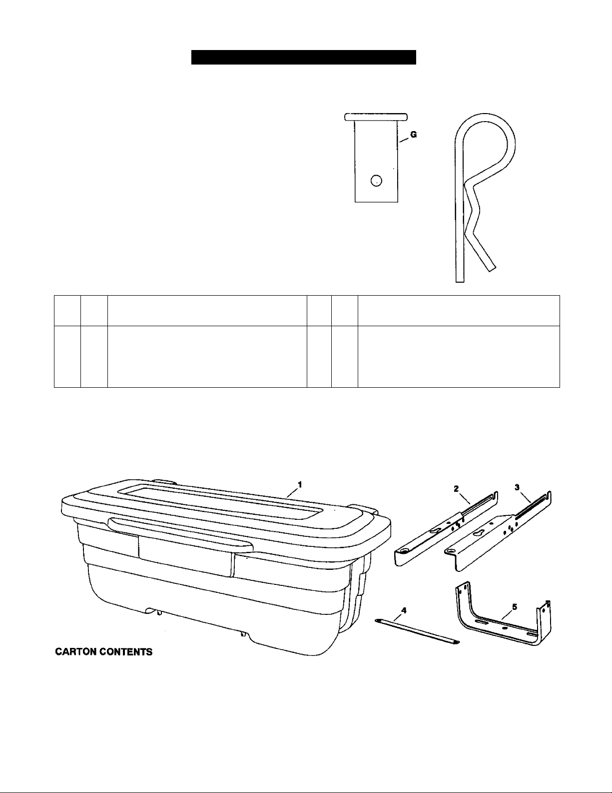
HARDWARE PACKAGE CONTENTS
HARDWARE SHOWN FULL SIZE
B
Ref.
Qty.
No.
Description
A 2
B 2
C 6
D
6 5/16" Hex Lock Nut
Shoulder Bolt
3/8" xr Hex Bolt
5/16’X 3/4" Hex Bolt
E 4
F
2 Bushing
G 1
H 3
3/8" Flanged Lock Nut
Clevis Pin
1/8" Hairpin Clip
1. Tool Box
2. Mounting Bracket, Left Hand
3. Mounting Bracket, Right Hand
4. Brace Strap
5. Hitch Bracket
Page 4

ASSEMBLY
TOOLS REQUIRED FOR ASSEMBLY
(1) 3/4" Wrench or Adjustable Wrench
(1) 11/16“ Wrench or Adjustable Wrench
(1) 5/8“ Wrench or Adjustable Wrench
(2) 9/16" Wrenches or Adjustable Wrenches
(2) 1/2" Wrenches or Adjustable Wrenches
• Remove the hardware pack and all parts from the
carton. Be sure the carton is empty before discard
ing.
• Lay out all parts and hardware as shown on page 3.
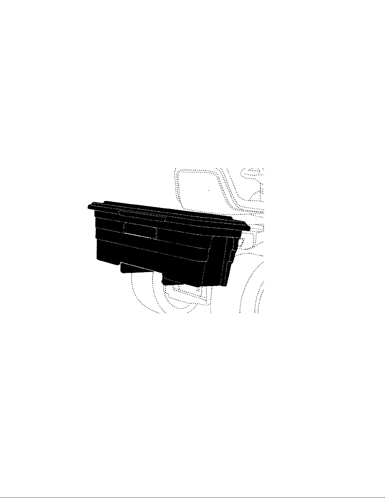
FOR TRACTORS RESEMBUNG FIGURE 1:
• Remove the bolt from the hole on each side of the
tractor frame as shown in figure 1.
• Assemble the two shoulder bolts to the now empty
holes. Tighten. See figure 1.
FOR TRACTORS RESEMBUNG FIGURE 2:
• Remove the bolt and nut from the hole on each side
of the tractor frame as shown in figure 3.
• Assemble two shoulder bolts and 3/8" flanged lock
nuts to the now empty holes. Tighten. See figure 3.
• Assemble the right and left mounting brackets to the
hitch bracket using four 5/16" x 3/4“ hex bolts emd
5/16" hex lock nuts. Do not tighten yet See figure 4.
LEFT HAND
MOUNTINQ BRACKET;
FIGURE 1
* Assemble the right hand and left hand mounting
brackets to the hitch bracket using four 5/16" x 3/4*
hex bolts and 5/16" hex lock nuts. Do not tighten
yet. See figure 2.
LEFT HAND
BRACKET
J
RIGHT HAND
MOUNTING BRACKET
FIGURE 4
FOR BOTH TYPES OF TRACTORS
• Assemble the brace strap to the mounting brackets
using two 5/16* X 3/4* hex bolts and 6/16* hex lock
nuts. Do not tighten yet. See figure 5.
• Assemble two 3/8" x 1" hex bolts, bushings and 3/8"
flanged lock nuts to the slots in the hitch bracket. Do
not tighten yet. See figure 5.
5/16" x 3/4"
HEX BOLT
FIGURE 2
MOUNTINQ
BRACKET
Page 5

Place the loosely assembled frame onto the rear of
the tractor, hooking the notched ends of the mounting
brackets under the shoulder bolts. Attach the hitch
bracket to the tractor hitch using the clevis pin and a
1/8" hairpin clip. See figure 6.
Align the frame so that it is straight and level with the
tractor. Tighten the four 5/16" x 3/4" hex bolts
(assembled in figure 4) which fasten the mounting
brackets to the hitch bracket.
Slide the 3/8" x 1" hex bolts along the hitch bracket
slots until they are bumped up against the back edge
of the tractor hitch. Tighten. See figure 6.
Place the tool box onto the frame so that №e heads
of the shoulder bolts in the bottom of the tool box fit
down Into the keyhole slots. Slide the tool box
fonward, slightly tilting up the back end, until the
clevis pins in the bottom of the tool box drop down
into the holes at the rear of the frame. Secure the tool
box to the frame with two 1/8" hairpin clips through
the clevis pins. See figure 7.
Tighten the two bolts (assembled in figure 5) which
fasten the brace strap to the mounting brackets. The
strap keeps the frame at the correct alignment width
when removing and reattaching the frame and the tool
box.
CAUTION: Vehicle braking and stability
may be affected with the addition of an
A
Engage the tractor clutch smoothly when starting
the tractor in motion. Sudden, full throttle starts
could cause the front end of the tractor to lift off the
ground, causing loss of steering control.
Fill the Trac Pack with up to 100 pounds of material
or tools.
Do Not exceed the 100 pound weight capacity of
the Trac Pack.
accessory or an attachment. Be aware of
changing conditions on slopes.
MAINTENANCE/STORAGE
• Rinse or wipe off the Trac Pack after each use.
• Do not store with material in the tool box.
OPERATION
To remove the tool box from the Trac Pack frame,
remove the 1/8" hairpin clips from the two clevis pin
in the bottom of the tool box. Lift up the rear of the
tool box enough to raise the pins out of the frame
and then pull back and up to remove the heads of
the shoulder bolts from the slots in the frame.
To remove the Trac Pack frame from the tractor,
remove the 1/8* hairpin clip and the clevis pin from
the hitch bracket. Unhook the frame from the
shoulder bolts on the sides of the tractor and
remove the frame. The shoulder bolts may be left
permanently attached.
Store inside in a clean, dry area.
Page 6

REPAIR PARTS FOR MODEL 486.24635
REF.
NO.
1
2
3
4
5
6
7
8
9
10
11
PART
NO.
47492
47493 1
47525 2
44044
43013 4
43088 4
43070 2
738-0255
46556 2
24560 1
24559 1
QTY.
1
Tool Box
Tool Box Lid
2
Clevis Pin, 3/8’ x 3/4" Lg.
Hex Lock Nut, 1/4-20 Thd.
Washer, 1/4"
Washer, 3/8“
2
Shoulder Bolt, 1/4-20 x .36" Lg.
Push Nut, 3/8“
Mounting Bracket, Right Hand
Mounting Bracket, Left Hand
DESCRIPTION REF.
Hex Bolt, 1/4-20 x 4-1/2’ Lg.
PART
NO.
12
13 24561
14
15
16
17
18 43343
19
20 43001
21
NO.
24567
738-0234
47572 4
43182 6
43064
711-0309 1
23625 2
47494 1
QTY.
1
1
2
6
3
2
DESCRIPTION
Brace Strap
Hitch Bracket
Shoulder Bolt, 3/8-16 x 5/8’ Lg.
Hex Lock Nut, Flanged 3/8-16 fhd.
Hex Bolt, 5/16-18 X 3/4“ Lg.
Hex Lock Nut, 5/16-18 Thd.
Hairpin Clip, 1/8" (#4)
Clevis Pin, 5/8" X 1.2" Lg.
Hex Bolt, 3/8-16 x1"Lg.
Bushing, Pivot
Owners Manual
Page 7

SLOPE GUIDE
(Keep this sheet in a safe place for future reference.)
Use this guide to determine If a slope is safe for the operation of your tractor and Trac Pack.
Refer also to the Instructions In your vehicle owners manual.
Page 8

For in>home major brand repair service:
Call 24 hours a day, 7 days a week
1-800-4-MY-HOME"** {1-800-4б9-4ббЗ)
Para pedir servicio de reparación a domiciiio -1-800-676-5811
In Canada for all your service and parts needs call
Au Canada pour tout le service ou les pieces
For the repair or repiacement parts you need:
Call 7 am - 7 pm, 7 days a week
-1-800-665-4455
1-800-366-PART (1-800-366-7278)
Para ordenar piezas con entrega a domiciiio -1-800-659-7084
For the iocation of a Sears Parts and Repair Center in your area:
Call 24 hours a day, 7 days a week
1-800-488-1222
For information on purchasing a Sears Maintenance Agreement
or to inquire about an existing Agreement:
PRINTED IN U.S.A.
Call 9 am - 5 pm, Monday - Saturday
1-800-827-6655
Tlie Service Side of Sears'
FORM NO. 47494
 Loading...