

Craftsman 486.246231 User Manual

TRACTOR BRUSH GUARD
this manual and fol low all Safe ty
Operating In struc tions.
• Safety
• Assembly
• Operation
• Maintenance
• Parts
Sears, Roebuck and Co., Hoffman Estates, IL 60179 U.S.A.
www.sears.com/craftsman
®
Any power equipment can cause injury if operated improperly or if the user does not understand how to operate the
equipment. Exercise caution at all times, when using power equipment.
• Refer to your tractor owners manual for
"Rules For Safe Operation"
precautions. It means —
Attention!! Become
alert!! Your safety is involved.
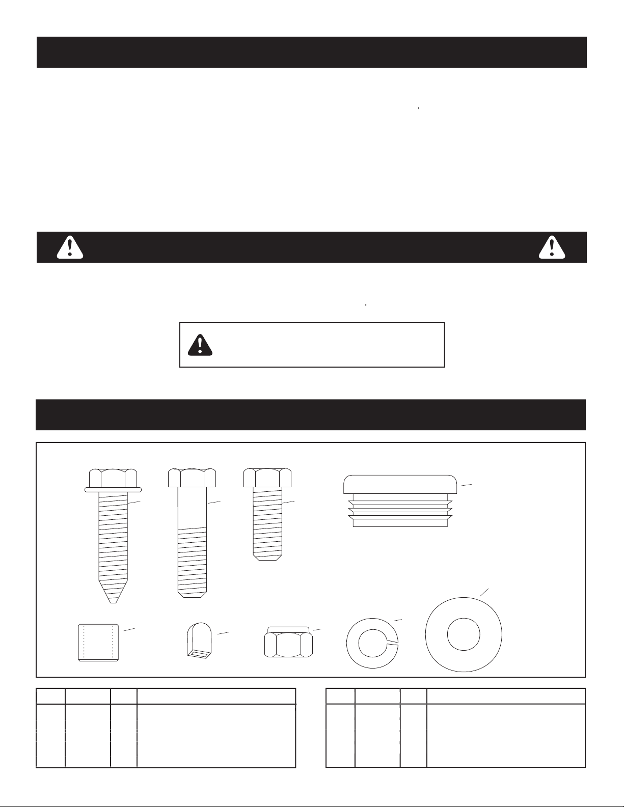
Ref. Part No. Qty. Description
Ref. Part No. Qty. Description
A 48894 2 Self Threading Screw, 3/8-16 x 1-1/2"
B 43062 2 Hex Bolt, 3/8-16 x 1-1/2"
C 43001 2 Hex Bolt, 3/8-16 x 1"
D 44742 4 Plug
E 48866 2 Pivot Spacer
SHOWN FULL SIZE
BA
C
G
H
D
E
I
F
F 1643-60 2 Plastic Grip
G HA21362 4 Nylock Nut, 3/8"
H 43003 4 Lock Washer, 3/8"
I 43070 4 Washer, 3/8"
Ref. Part No. Qty. Description
Ref. Part No. Qty. Description
ONE YEAR LIMITED WARRANTY
When operated and maintained according to the instructions supplied with it, if this Tractor Brush Guard fails due to a defect in
material or workmanship within one year from the date of purchase, call 1-800-4-MY-HOME
®
to arrange for free repair.
This warranty gives you specifi c legal rights, and you may also have other rights which vary from state to state.
Sears, Roebuck and Co., D817WA, Hoffman Estates, IL 60179
WARRANTY
SAFETY
HARDWARE PACKAGE
3
1
2
3
4
1 Right Mounting Bracket #25038
2 Left Mounting Bracket #25037
3 Locking Lever #64862
4 Bumper #64614B (71-246212)
#64614S (71-246221)
#64614C (71-246231)
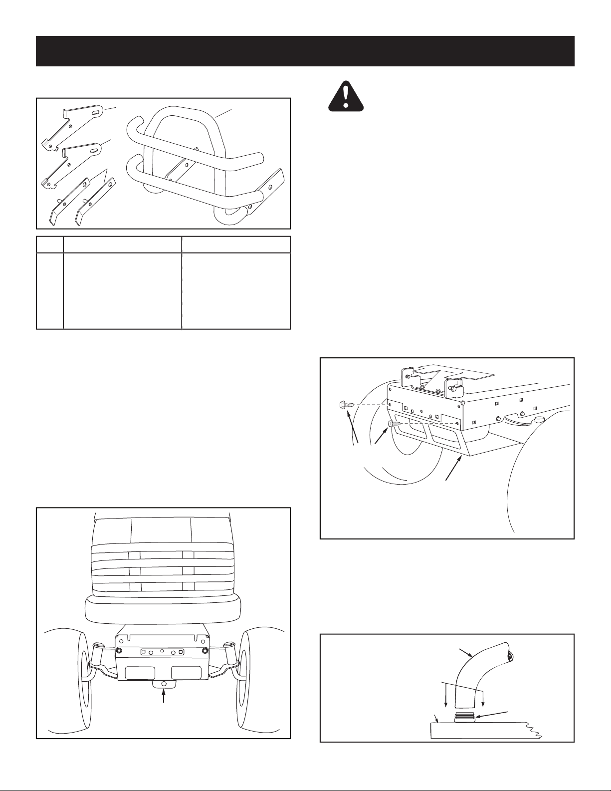
ASSEMBLY
ASSEMBLING TO SINGLE ROD DECK
SUSPENSION TRACTORS
suspension bracket located under the middle of the front
axle as shown in fi gure 1, continue with the instructions
on this page. If your tractor does not have a mower deck
suspension bracket like the one shown, go to page 5.
MOWER DECK
SUSPENSION
BRACKET
STEP 1:
(SEE FIGURE 2)
• Place cardboard on work surface.
• Identify and lay out all parts and hardware. Not all
discarded after assembly.
• Remove hood from tractor using instructions in your
tractor owner's manual. Place hood on cardboard or
on a mat to protect paint.
• Remove the browning shield from the front of the
tractor as shown.
the browning shield
after bumper is installed.
REMOVE
BROWNING SHIELD
REMOVE
FRONT SCREWS
STEP 2:
(SEE FIGURE 3)
• Place plug (D) on a work bench or solid table and
push end of bumper down onto plug. Repeat for all
four plugs.
PLUG (D)
BUMPER
PUSH DOWN
WITH EVEN
PRESSURE
WORK BENCH
OR SOLID TABLE
CARTON CONTENTS
CAUTION!
Muffl er is hot! Allow engine to
cool down before proceeding with bumper
TOOLS REQUIRED
Right hand (RH) and left hand (LH) are
determined from the operator's position while seated on
the tractor.
 Loading...