

Page 1

Owner's Manual
TRACTOR BRUSH GUARD
Model No's. 486.246212, 486.246221 & 486.246231
_ii..........i_ _'_:('_ •.....•.............
CAUTION:
Before using this product, read
this manuaU and follow aH Safety
RuUes and
Operating Instructions.
• Safety
• AssembLy
,, Operation
• Maintenance
• Parts
IMPORTANT - READ THtS FIRST!!!
For Missing Parts or AssembUy Questions
PUease Call 866-576-8388
Mon.-Fri. 7 am - 5 pm CST.
FAX 217-728-2032 or e-mail info@aq_ri-fab.com
Missing parts will be sent UPS in 24 hours directly to your home.
Sears, Roebuck and Co., Hoffman Estates, IL 60179 U.S.A.
www, sears,com/craftsman
PRINTED IN U.S.A. FORM NO. 49790 (9/05)
Page 2
ONE YEAR UMITED WARRANTY
When operated and maintained according to the instructions supplied with it, if this Tractor Brush Guard fails due to a defect in
material or workmanship within one year from the date of purchase, cal! 1-800-4-MY-HOME ®to arrange for free repair.
If this product is used for commercial or rental purposes, this warranty applies for only 90 days from the date of purchase.
This warranty gives you specific legal rights, and you may also have other rights which vary from state to state.
Sears, Roebuck and Co., D817WA, Hoffman Estates, mL60179
Any power equipment can cause injury if operated improperly or if the user does not understand how to operate the
equipment, Exercise caution at all times, when using power equipment,
Refer to your tractor owners manual for "Rules For Safe Operation",
Look for this symbol to point out important safety
precautions, It means -- Attention!! Become
alert!! Your safety is involved,
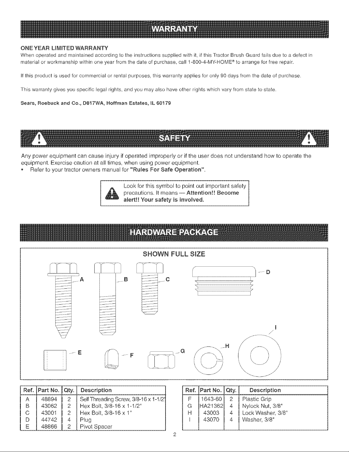
SHOWN FULL SiZE
........ E
Ref. Part No. Qty. Description
A 48894 2 SelfThreading Screw, 3/8-16 x 1-1/2
B 43062 2 Hex Bolt, 3/8-16 x 1-1/2"
C 43001 2 Hex Bolt, 3/8-16 x 1"
D 44742 4 Plug
E 48866 2 Pivot Spacer
...... F
Ref. PaA No.
F 1643-60
G HA21362
H 43003
] 43070
2
/ .... D
t
/
J
Qty, Description
2 Plastic Grip
4 Nylock Nut, 3/8"
4 Lock Washer, 3/8"
4 Washer, 3/8"
Page 3
CARTON CONTENTS
Ref, Description
1 Right Mounting Bracket
2 Left Mounting Bracket
3 Locking Lever
4 Bumper
TOOLS REQUIRED
(2) 9/16" Wrenches
(1) 1/2" Wrench (for heat shield on page 5)
Part No.
#25038
#25037
#64862
#64614B (71-246212)
#64614S (71-246221)
#64614C (71-246231)
CAUTION! Muffler is hot! Allow engine to
cool down before proceeding with bumper
installation,
NOTE: Right hand (RH) and left hand (LH) are
determined from the operator's position while seated on
the tractor,
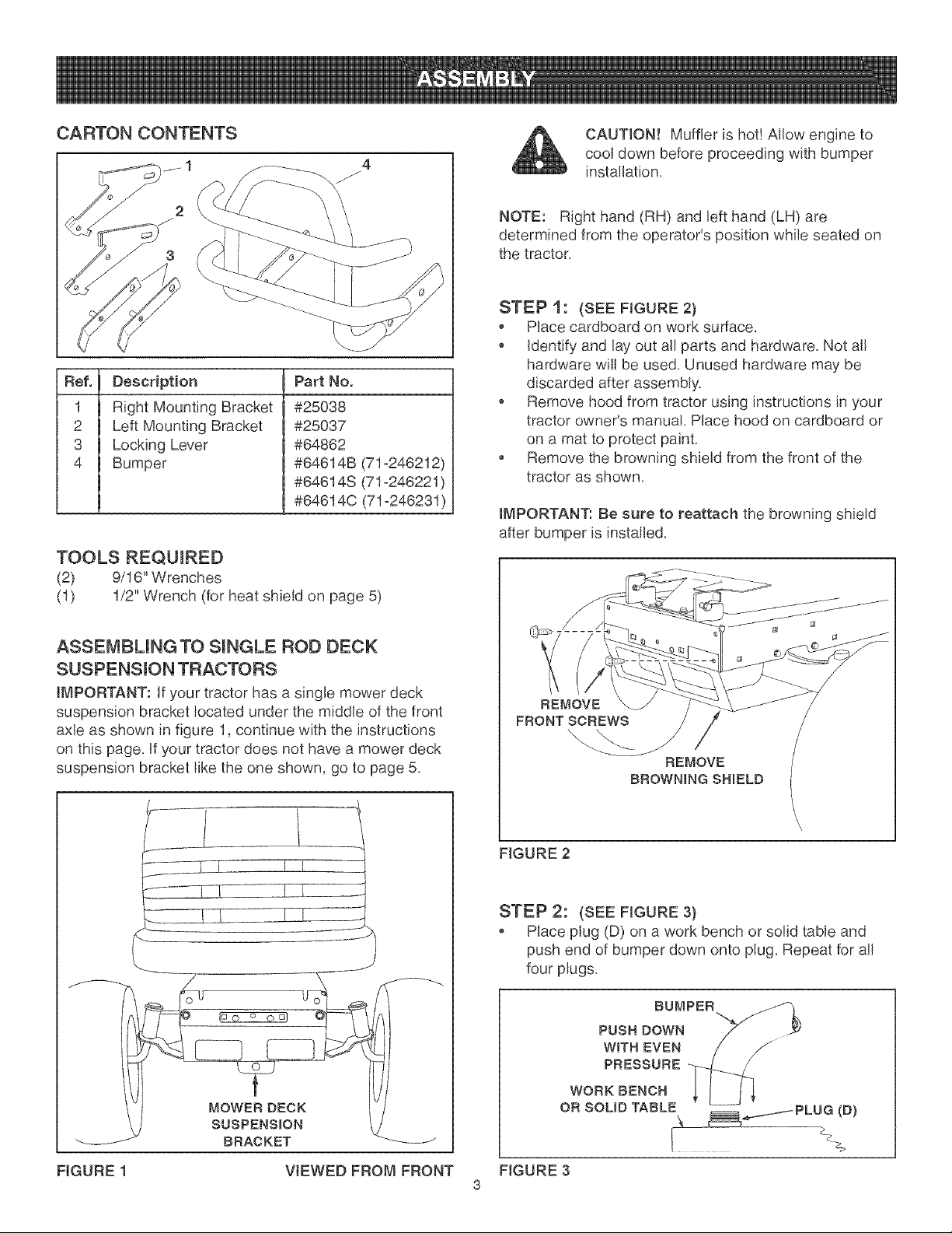
STEP 1: (SEE FIGURE 2)
, Place cardboard on work surface.
identify and lay out all parts and hardware. Not all
hardware wil! be used. Unused hardware may be
discarded after assembly.
Remove hood from tractor using instructions in your
tractor owner's manual. Place hood on cardboard or
on a mat to protect paint.
, Remove the browning shield from the front of the
tractor as shown.
IMPORTANT: Be sure to reattach the browning shield
after bumper is installed,
ASSEMBLING TO SINGLE ROD DECK
SUSPENSmON TRACTORS
IMPORTANT: If your tractor has a single mower deck
suspension bracket located under the middle of the front
axle as shown in figure 1, continue with the instructions
on this page, if your tractor does not have a mower deck
suspension bracket like the one shown, go to page 5,
I I
_J
REMOVE
FRONT SCREWS
REMOVE
BROWNmNGSHmELD
FIGURE 2
STEP 2: (SEE FIGURE 3}
Place plug (D) on a work bench or solid table and
push end of bumper down onto plug. Repeat for all
four plugs.
BUMPER
PUSH DOWN
WiTH EVEN
PRESSURE
WORK BENCH
FIGURE 1
BRACKET
VIEWED FROM FRONT
OR SCUD TABLE
FIGURE 3
3
Page 4

STEP 3: (SEE FIGURE 4)
, Attach left mounting bracket to hole shown in left side
of tractor frame using a hex bolt (C), fiat washer (I)
and nylock nut (G). Align middle hote in bracket with
empty hole in tractor frame. Tighten nylock nut (G)
only enough to keep bracket in alignment until step 4.
Repeat for right mounting bracket.
(GT) FRAME SHOWN
HEX LEFT MOUNTING
BUMPER STOPS BOLT (C) BRACKET
FACE OUT _ NYLOCK
NUT(G)
FLAT
WASHER (0
/
AUGN THESE HOLES
STEP 5: (SEE FIGURE 6)
, Replace the front screws and browning shield you
removed in Step 1 as shown.
FRONT SCREWS
REPLACE
BROWNmNG SHmELD
FIGURE 6 LEFT SIDE VIEW
FIGURE 4
LEFT SIDE VIEW
STEP 4: (SEE FIGURE 5)
, Fasten bumper to mounting bracket using a hex bolt
(B), pivot spacer (E), a locking lever, a fiat washer
(I) and a ny!ock nut (G) as shown, The pivot spacer
inserts into hole in bumper. Tighten both nuts on
mounting bracket at this time. Repeat for other side.
, Assemble plastic grips (F) onto locking levers.
, Lift up on bumper until pins in locking levers snap into
holes in mounting brackets.
IMPORTANT: You must lower bumper before raising tractor
hood. Pu!! out on locking levers and push bumper down as
far as it will go.
PIVOT
SPACER (E)_
FIGURE 5
FLAT
WASHER (I)
GRUP (F)
LEFT SIDE VIEW
Page 5

ASSEMBLING TO DUAL ROD DECK
SUSPENSION TRACTORS
IMPORTANT: These instructions are for tractors with
dual mower deck suspension brackets like the examples
shown in figure 2 on this page..
CAUTION! Muffler is hot! Allow engine to
cool down before proceeding with bumper
installation,
NOTE: Right hand (RH) and left hand (LH) are
determined from the operator's position while seated on
the tractor,
STEP 1 :
, Place cardboard on work surface,
, identify and lay out all parts and hardware, Not all
hardware witl be used, Unused hardware may be
discarded after assembly,
, Remove tractor hood, (Refer to tractor manua!,) Place
hood on cardboard or on a mat to protect paint,
STEP 3: (SEE FIGURE 2)
IMPORTANT: Do not remove any bolts from the tractor
frame while the mower deck is raised, Misatignment of
holes in frame could result,
Lower mower deck to rest on ground,
Remove bolts from mounting holes on both sides of
tractor frame, Use a mounting bracket to help identify
holes,
(LT) LAWN TRACTOR
REMOVE BOLT
iFPRESENT
/
SUSPENSION BRACKET
(LT) LAWN TRACTOR
STEP 2: (SEE FIGURE 1)
, if you have an (LT) Lawn Tractor with a heat shield
like the one shown, remove the heat shield,
IMPORTANT: Be sure to re-attach the heat shield after
bumper is installed,
(LT) LAWN TRACTOR
-_/ REMOVE THIS
STYLE HEAT SHIELD
REMOVE BOLT
/
SUSPENSION
BRACKET
(GT) GARDEN TRACTOR
REMOVE BOLT
UF PRESENT
FIGURE 1
FIGURE 2
Page 6

STEP 4: (SEE F_GURE3}
, Attach left mounting bracket to hole shown in left side
of tractor frame using bolt (C), !ock washer (H) and
flat washer (I). Align middle hole in bracket with empty
hole in tractor frame and tighten bolt (C) to hold
bracket in place. Repeat for right mounting bracket.
(GT) FRAME SHOWN
STEP 6: (SEE FIGURES 5 AND 6}
, Assemble plastic grips (F) onto locking levers.
, To attach bumper to tractor:
1. Place flattened ends of bumper onto mounting
brackets. Insert pin of locking lever through front
hole in bumper and into front hole in mounting
bracket to support bumper on mounting bracket.
2. insert pivot spacers (E) into rear holes in bumper.
ATTACH TO
THRSHOLE
BUMPER STOPS
FACE OUT
FIGURE 3
LEFT MOUNTING FLAT
BRACKET WASHER BOLT
(0 (c}
LOCK
WASHER
(H}
/
ALIGN THESE HOLES
LEFT SiDE VIEW
PUVOT
SPACER
LOCKING LEVER
J
FIGURE 5
,
Fasten locking lever and bumper to mounting bracket
using a screw (A) or bolt (B), a lock washer (H) and a
flat washer (I). Use screw (A) for LTtractors and bolt
(B) for GT tractors. Assemble screw or bolt through
pivot spacer in rear hole in bumper and into tractor
frame. Tighten. Repeat for other side.
/
GRUP (F)
I
LEFT SIDE VIEW
(E)_
STEP 5: (SEE FIGURE 4)
, Place plug (D) on a work bench or solid table and
push end of bumper down onto ptug. Repeat for al!
four plugs.
BUMPER
PUSH DOWN
WUTH EVEN
PRESSURE
WORK BENCH
OR SOLID TABLE __ PLUG (B)
FIGURE 4
\
NOTE: If hole in (LT) tractor frame is not threaded, push
in while turning screw (A) to create threads in hole.
IMPORTANT: You must lower bumper before raising tractor
hood. Pu!! out on locking levers and push bumper down as
far as it will go.
FLAT I
WASHER d)
/
FIGURE 6
LEFT S_DE VIEW
Page 7

Page 8

1111111111111117`¸
iiiiiiiiiiiiiiiiii
iiiiiiiiiiiiiiiiii
iiiiiiiiiiiiiiiiii
iiiiiiiiiiiiiiiiii
iiiiiiiiiiiiiiiiii
iiiiiiiiiiiiiiiiii
iiiiiiiiiiiiiiiiii
iiiiiiiiiiiiiiiiii
iiiiiiiiiiiiiiiiii
iiiiiiiiiiiiiiiiii
iiiiiiiiiiiiiiiiii
iiiiiiiiiiiiiiiiii
iiiiiiiiiiiiiiiiii
iiiiiiiiiiiiiiiiii
iiiiiiiiiiiiiiiiii
iiiiiiiiiiiiiiiiii
iiiiiiiiiiiiiiiiii
iiiiiiiiiiiiiiiiii
iiiiiiiiiiiiiiiiii
iiiiiiiiiiiiiiiiii
iiiiiiiiiiiiiiiiii
iiiiiiiiiiiiiiiiii
iiiiiiiiiiiiiiiiii
Your Home
For repair-in your home-of all major brand appliances,
lawn and garden equipment, or heating and cooling systems,
no matter who made it, no matter who sold it!
For the replacement parts, accessories and
owner's manuals that you need to do-it-yourself.
For Sears professional installation of home appliances
and items like garage door openers and water heaters.
1-800-4-MY-HOME ® (1-800-469-4663)
Call anytime, day or night (U.S.A. and Canada)
www.sears.com www.sears.ca
iiiiiiiiiiiiiiiiiiiiiiiiT_
iiiiiiiiiiiiiiiiii
iiiiiiiiiiiiiiiiii
iiiiiiiiiiiiiiiiii
iiiiiiiiiiiiiiiiii
iiiiiiiiiiiiiiiiii
iiiiiiiiiiiiiiiiii
iiiiiiiiiiiiiiiiii
iiiiiiiiiiiiiiiiii
iiiiiiiiiiiiiiiiii
iiiiiiiiiiiiiiiiii
iiiiiiiiiiiiiiiiii
iiiiiiiiiiiiiiiiii
iiiiiiiiiiiiiiiiii
iiiiiiiiiiiiiiiiii
1-888-SU-HOGAR ®
(1-888-784-6427'
® Registered Trademark / Trademark / SM Service Mark of Sears Brands, LLC
® Marca Registrada / Marca de F_brica / Marca de Servicio de Sears Brands, LLC
MC MD
Marque de commerce / Marque d6pos6e de Sears Brands, LLC ® Sears Brands, LLC
TM
TM SM
(1-800-533-6937)
www.sears.ca
 Loading...