

Page 1
Owner's IVlanuai
CRRFrSMI N
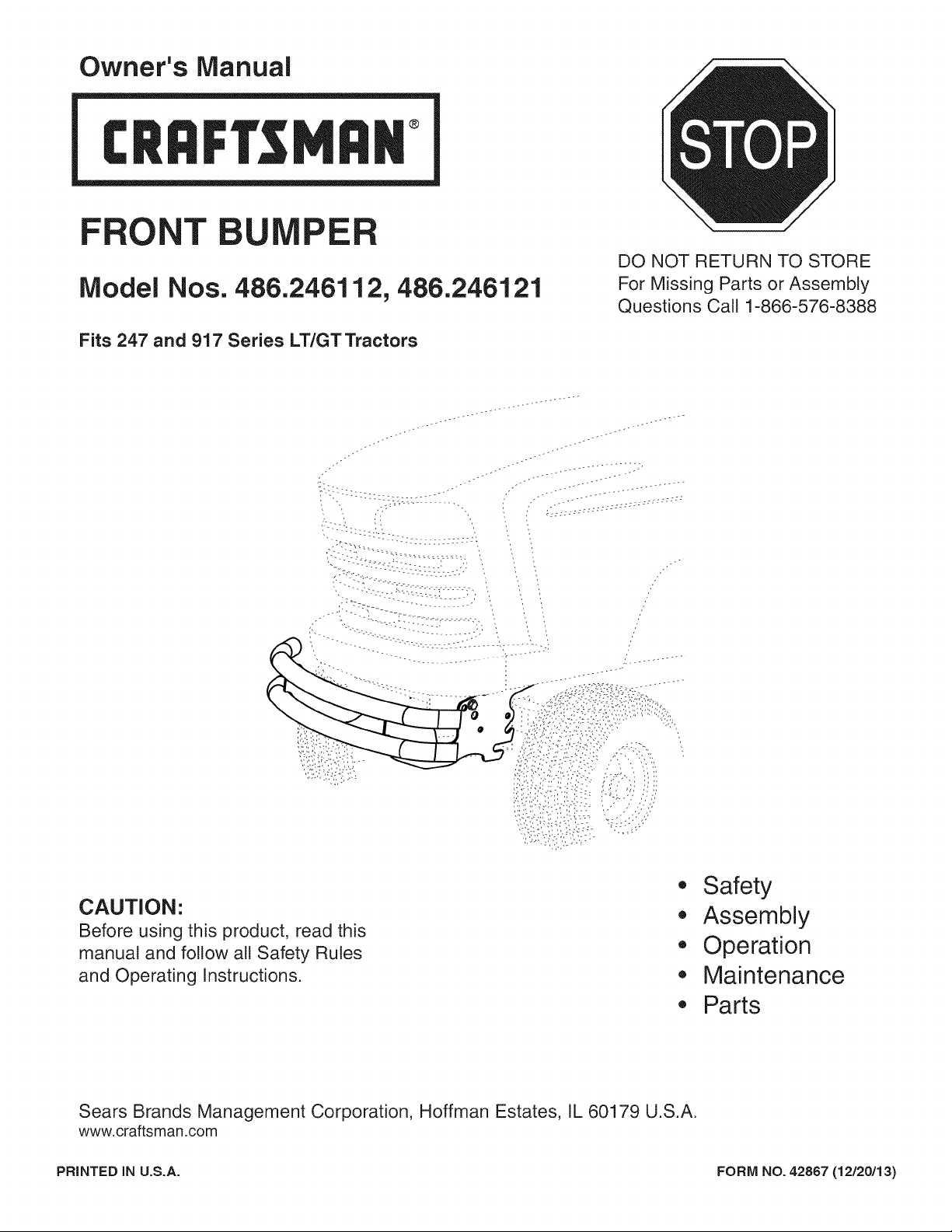
FRONT U E
IVlodel Nos. 486.246112, 486.246121
Fits 247 and 917 Series LT/GT Tractors
...... iiiiiiiill
/ /,'" ;_===================================
, ----:::::',:L
DO NOT RETURN TO STORE
For Missing Parts or Assembly
Questions Call 1-866-576-8388
• Safety
CAUTION:
Before using this product, read this
manual and follow all Safety Rules
and Operating Instructions.
Sears Brands Management Corporation, Hoffman Estates, IL 60179 U.S.A.
www.craftsman.com
PRINTED IN U.S.A. FORM NO. 42867 (12/20/13)
• Assembly
• Operation
,, Maintenance
,, Parts
Page 2
WARRANTY
CRAFTSMAN ONE YEAR FULL WARRANTY
FOR ONE YEAR from the date of purchase, this product is warranted against any defects in material or workmanship. A defective
product will be replaced free of charge.
For warranty coverage details to obtain free replacement, visit the web site: www.craftsman.com
This warranty is void if this product is ever used while providing commercial services or if rented to another person.
This warranty gives you specific legal rights, and you may also have other rights which vary from state to state.
Sears Brands Management Corporation, Hoffman Estates, IL 60179
DO NOT RETURN TO STORE for Missing Parts or Assembly Questions
Call 1-866-576-8388 Attachment Hotline
SAFETY
Any power equipment can cause injury if operated improperly
or if the user does not understand how to operate the
equipment. Exercise caution at all times when using power
equipment.
• Refer to your tractor owners manual for "Rules For
Safe Operation".
Look forthis symbol to point out important safety
precautions. It means -- Attention!! Become
alert!! Your safety is involved.
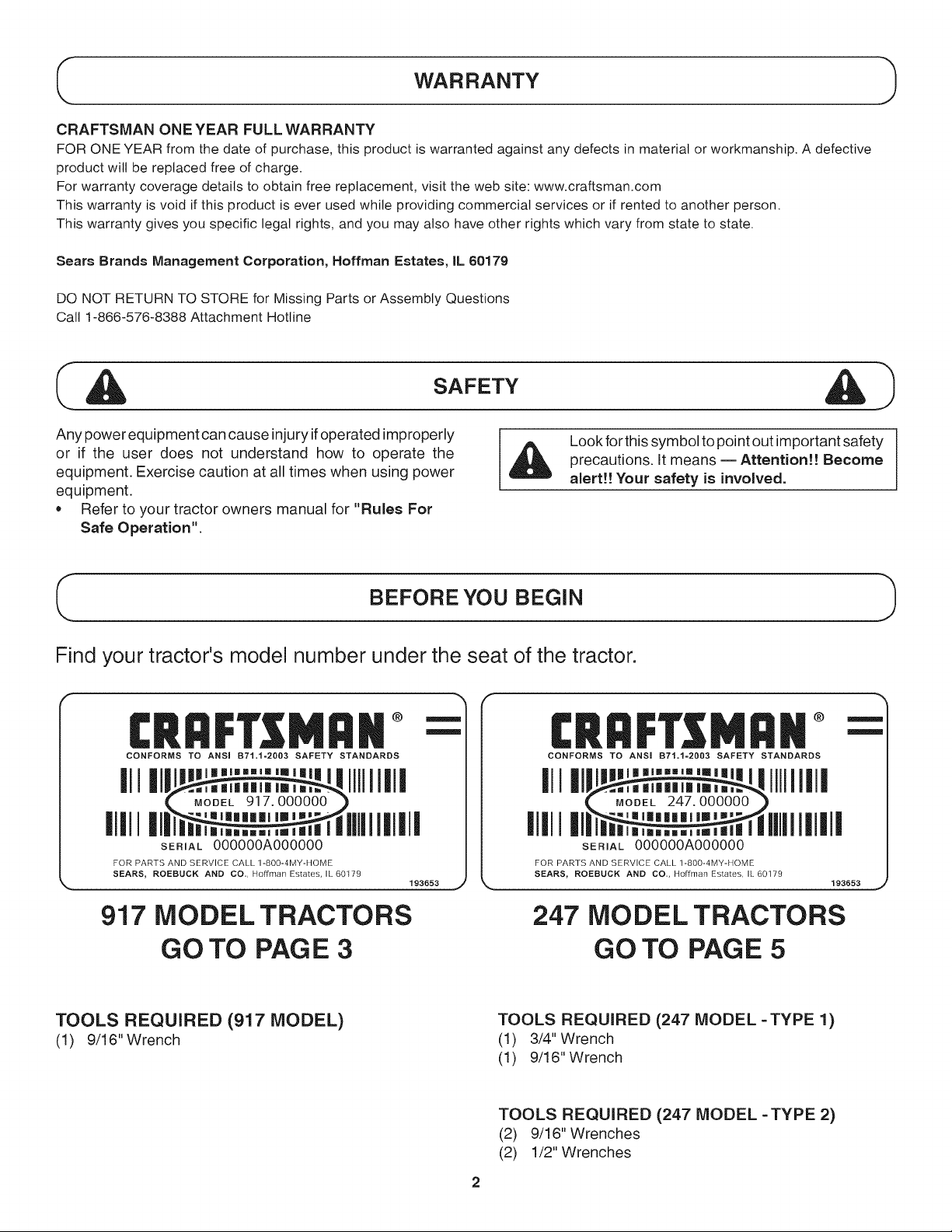
BEFORE YOU BEGIN
Find your tractor's model number under the seat of the tractor.
CRRFT MR#
CONFORMS TO ANSi B71.1=2003 SAFETY STANDARDS
III |11 '"'"'" IIII1|11
IIIII I|1|I
SERIAL 000000A000000
FOR PARTS AND SERVICE CALL 1-800-4MY-HOME
SEARS, ROEBUCK AND CO., Hoffman Estates, IL 60179
193653
CONFORMS TO ANSi B71.1=2003 SAFETY STANDARDS
III|11 '"'""'" IIIII1|I
IIIII ,.....,,. IIIIIIIIIII
SERIAL 000000A000000
FOR PARTS AND SERVICE CALL 1-80O-4MY-HOME
SEARS, ROEBUCK AND CO., Hoffman Estates, IL 60179
193653
917 MODEL TRACTORS
GO TO PAGE 3
TOOLS REQUIRED (917 MODEL)
(1) 9/16" Wrench
247 MODEL TRACTORS
GO TO PAGE 5
TOOLS REQUIRED (247 MODEL =TYPE 1)
(1) 3/4" Wrench
(1) 9/16" Wrench
TOOLS REQUIRED (247 MODEL =TYPE 2)
(2) 9/16" Wrenches
(2) 1/2" Wrenches
Page 3
iNSTRUCTiONS FOR 917 MODEL TRACTORS
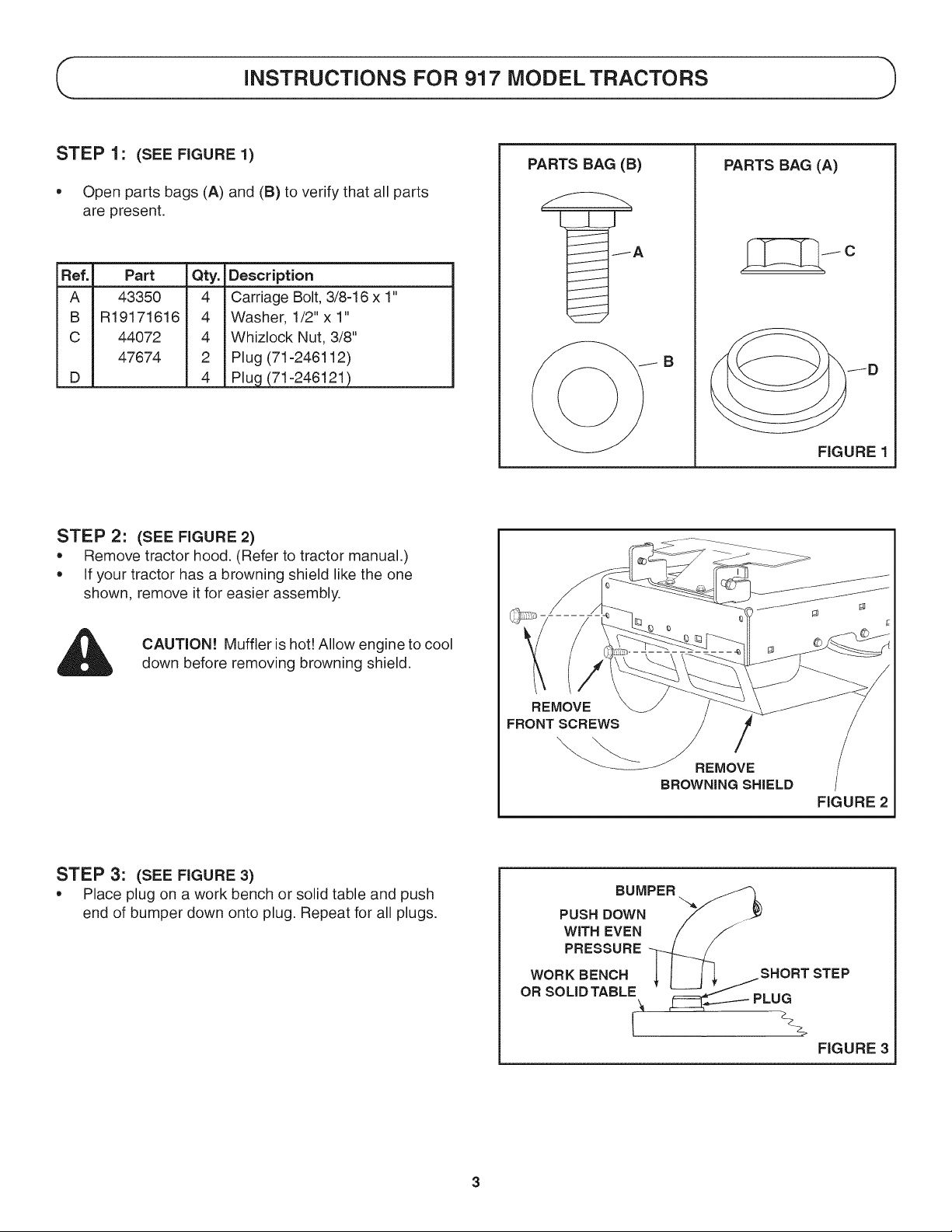
STEP 1: (SEE FIGURE 1)
• Open parts bags (A) and (B) to verify that all parts
are present.
Ref. Part Qty. Description
A 43350 4 Carriage Bolt, 3/8-16 x 1"
B R19171616 4 Washer, 1/2"x 1"
C 44072 4 Whizlock Nut, 3/8"
47674 2 Plug (71-246112)
D 4 Plug (71-246121)
STEP 2: (SEE FIGURE 2)
Remove tractor hood. (Refer to tractor manual.)
If your tractor has a browning shield like the one
shown, remove it for easier assembly.
PARTS BAG (8)
PARTS BAG (A)
c
B
/D
FIGURE 1
CAUTION! Muffler is hot! Allow engine to cool
down before removing browning shield.
STEP 3: (SEE FIGURE 3)
Place plug on a work bench or solid table and push
end of bumper down onto plug. Repeat for all plugs.
REMOVE
FRONT SCREWS
REMOVE
BROWNING SHIELD
FIGURE 2
BUMPER
PUSH DOWN
WiTH EVEN
PRESSURE
WORK BENCH
OR SOLIDTABLE
I
Page 4

STEP 4: (SEE FIGURE 4)
• Place washers onto two carriage bolts.
• Place the bumper over the front of the tractor frame
and insert the bolts through the rear holes in the
tractor frame and the slots in the bumper. Install
whizlock nuts onto the bolts but do not tighten yet.
WHIZLOCK
NUT
CARRIAGE BOLT
AND WASHER
FIGURE 4
STEP 5:
e
Place washers onto two carriage bolts.
e
Insert the bolts through the front holes in the tractor
frame and the mounting holes in the bumper. The rear
mounting hole gives the most clearance while the
front hole gives a neater appearance. Use a hole that
provides enough clearance for the hood to stay in the
raised position when opened.
Install whizlock nuts onto the bolts and tighten all
four bolts and nuts.
IMPORTANT: Before fully tightening nuts, be sure
tractor hood will stay in raised position when opened.
(SEE FIGURE 5)
STEP 6: (SEE FIGURE 6)
• Replace the browning shield using the front screws
you removed in Step 2.
CARRIAGE BOLT
AND WASHER
I
WHIZLOCK NUT
FIGURE 5
REPLACE
FRONT SCREWS
/
REPLACE
BROWNINGSHIELD
FIGURE 6
Page 5

iNSTRUCTiONS FOR 247 MODEL TRACTORS
iDENTiFY YOUR TRACTOR FRAME
Look at the side of your tractor frame directly below the hood. If your frame looks like the TYPE 1 frame, go to page 6 for
assembly instructions. If your frame looks like the TYPE 2 frame, go to page 7 for assembly instructions.
TYPE 1 TYPE 2
/
/
NOTE: Only the front of the tractor frame is shown.
PART BAGS FOR TYPE 1 AND TYPE 2 FRAMES
STEP 1" (SEE FIGURE 1)
* Open parts bags labelled (A) and (C) and verify that
all parts are present.
NOTE: Not all items in the parts bags will be needed.
Discarded unneeded items after assembly is completed.
Ref. Part
C 44072 4
D 47674 2
E 48106 2
F 47856 2
G 43001 2
H 46584 2
I 43182 2
Qty. Description
Whizlock Nut, 3/8"
Plug (71-246112)
4
Plug (71-246121 )
Shoulder Bolt, 3/8-16 x .9"
Lag Screw, 5/16 x 3/4"
Hex Bolt, 3/8-16 x 1"
Whizlock Nut, 5/16"
Hex Blot, 5/16 x 3/4"
PARTS BAG (A)
JD
PARTS BAG (C)
FIGURE 1
Page 6

TYPE 1 TRACTOR FRAME
STEP 2: (SEE FIGURE 2)
* Place plug on a work bench or solid table and push
end of bumper down onto plug. Repeat for all plugs.
STEP 3: (SEE FIGURE 3)
* Assemble a 0.9 x 3/8" shoulder bolt and 3/8" whizlock
nut to each side of the tractor frame. Tighten.
CAUTION! Muffler is hot! Allow engine to
cool down before proceeding with bumper
installation.
BUMPER
PUSH DOWN
WiTH EVEN
PRESSURE
WORK BENCH
OR SOLIDTABLE
3/8" WHIZLOCK
NUT _. 1
SHORT STEP
__'_PLUG
_z FIGURE 2
SHOULDER
BOLT
" 1
FIGURE 3
STEP 4: (SEE FIGURE 4)
• Slide the lower slots of the bumper onto the shoulder
bolts you assembled to the tractor frame in step 1.
STEP 5: (SEE FIGURE 5)
* Assemble a 5/16 x 3/4" lag screw to the bumper and
tractor frame.
* Repeat for other side.
FIGURE 4
FIGURE 5
Page 7

TYPE 2 TRACTOR FRAME
STEP 2: (SEE FIGURE 2)
* Place plug on a work bench or solid table and push
end of bumper down onto plug. Repeat for all plugs.
STEP 3: (SEE FIGURE 3)
* Assemble a 3/8 × 1" hex bolt and 3/8" whizlock nut to
tractor frame and middle slot of the bumper.
* Tighten and then loosen nut one half turn.
o Repeat for other side of bumper.
CAUTION! Muffler is hot! Allow engine to
cool down before proceeding with bumper
installation.
BUMPER
PUSH DOWN
WiTH EVEN
PRESSURE
WORK BENCH
OR SOLIDTABLE
I
STEP 4: (SEE RGURE 4)
Assemble a 5/16 x 3/4" hex bolt and 5/16" whizlock
nut to the tractor frame and bumper. Tighten.
Repeat for other side of bumper
Tighten the two 3/8" whizlock nuts assembled in
step 1.
3/8"WHIZLOCK
NUT RGURE 3
5/16" WHIZLOCK
NUT
FIGURE 4
Page 8

1 888 331 4569
ustom Care Hot
piezas o pedir servicio para la reparaci6n de su equipo.
To help us help you, register your product at www.craftsman.com/registration
Para poderte ayudar mejor, registra tu producto en www.craftsman.com/registration
Join the Craftsman Club today!
®
www.craftsman.com/signup
Receive exclusive member benefits including special pricing and offers,
project sharing, expert advice, and SHOP YOUR WAY REWARDS!
Como miembro exclusivo, recibe diversos beneficios como ofertas, precios especiales, proyectos
nuevos, consejos de expertos y nuestro programa de puntos SHOP YOUR WAY REWARDS!
® Registered Trademark / TMTrademark of KCD IP, LLC in the United States, or Sears Brands, LLC in other countries
® Marca Registrada / TMMarca de Fabrica de KCD IP, LLC en Estados Unidos, o Sears Brands, LLC in otros paises
 Loading...